Article

An Active Flow Control over the Ship Deck for Helicopter Shipboard Operations

1
National Key Laboratory of Helicopter Aeromechanics, College of Aerospace Engineering, Nanjing University of Aeronautics and Astronautics, Nanjing 210016, China
2
College of Aerospace Engineering, Chongqing University, Chongqing 400030, China
*
Author to whom correspondence should be addressed.
Aerospace 2024, 11(2), 119; https://doi.org/10.3390/aerospace11020119
Submission received: 23 October 2023 / Revised: 22 January 2024 / Accepted: 26 January 2024 / Published: 29 January 2024
(This article belongs to the Section Aeronautics)

Abstract

:
This paper presents an active flow control of ship airwake over the deck to improve the safety of helicopter shipboard operations in various angles of wind over deck (WOD). Firstly, an integrated flight dynamics method coupled with ship airwake was developed to analyze the effect of ship airwake on the helicopter at various angles of WOD. Then, an active flow control strategy in various angles of WOD was investigated with the analysis of airwake distribution and the impact on helicopter trim flight. Finally, the effects of active blowing on airwake distribution, flight control inputs, control margins, and helicopter attitudes in trim were analyzed. The results indicate that the variation of the angles of WOD has a significant impact on flight controls and helicopter attitudes for helicopter hovering relative to ship motion. The nonuniformity of ship airwake can be effectively alleviated by applying active flow control. The variations of flight control inputs and helicopter attitude angles at trim states are reduced, which increases the control margins and contributes to enhancing the safety of helicopter shipboard operations.

1. Introduction

Shipboard helicopter operation accidents mainly occur in the landing stage since landing a helicopter on the small ship deck such as a frigate is a difficult and demanding task for even the most experienced pilots because it is not easy to fully anticipate the aft airwake phenomenon. In addition to operating in a restricted landing zone, the helicopter also suffers from ship airwake caused by the airflow around the ship superstructure.
Many researchers have studied the flow patterns of ship airwake [1,2,3] and further used wind tunnel testing to study ship airwake characteristics under different wind conditions, such as various angles of wind over deck (WOD) [4,5,6]. Researchers have shown the complexity of ship airwake and preliminarily revealed the characteristics of the airwake and its impact on helicopters. Superstructures with non-streamlined features on the ship consist of blunt bodies, which obstruct the airflow through these surfaces, resulting in variation of the pressure field as well as a large spatial gradient of the velocity field along with flow separation, shedding vortex, and attachment. The main factors endangering the safety of shipboard helicopters are downwash and sidewash flows as well as shedding vortex in the recirculation region. Moreover, the airwake varies significantly with the angle of WOD.
Ship airwake is one of the important factors threatening the safety of helicopter shipboard operations. Unlike land-based take-offs and landings, shipboard helicopter take-offs and landings occur in winds from any direction relative to the helicopter. As the helicopter operates in the airwake, the unstable airflow can cause large fluctuations in the aerodynamic loading on the main rotor and fuselage, making it difficult for the pilot to maintain position and attitude [7,8,9] and resulting in large variations of flight controls and helicopter attitudes. In severe cases, the pilot does not have enough flight control margin, which can cause an accident. Therefore, reducing the variations of flight controls and helicopter attitudes during shipboard operations is beneficial for minimizing the risk of accidents and maximizing the ship–helicopter operating limits (SHOL) envelope [10,11]. For the reasons described above, flow control on the ship deck may be an effective way to reduce the variations of flight controls and helicopter attitudes.
Flow control technologies to suppress the unsteady flow in ship airwake have been studied in the past decades. Some researchers modified the geometric structure of the ship superstructure or hangar [12,13,14,15,16,17] through situ testing, computational fluid dynamics (CFD) simulations, and wind-tunnel-scale model experiments, i.e., passive control, to change the airwake flow patterns. Although passive control is applied in most ship airwake control methods [17], its biggest drawback is that it cannot actively adapt to the complex and changeable marine environment.
Unlike passive control, active controls can be flexibly applied to airwake control by automatically adjusting the energy input. Energy replenishment methods have been employed, for example, jet, blowing, or the Coanda effect, through CFD and wind-tunnel-scale model experiments [18,19,20,21] to control the flow component of the ship airwake. The plasma actuator has also been applied to reduce the unsteadiness of the airwake [22]. However, it is very unlikely that plasma actuation would scale to a real ship. Shafer et al. used porous surfaces to replace the solid surfaces of the hangar and flight deck; further improvements were found by injecting air through these porous surfaces, causing a reduction in unsteadiness in the landing region. Matías-García et al. showed the active flow control techniques tested, such as air blowing or suction from the hangar or the flight deck, can drastically reduce the flow detachment and the recirculation bubble on the flight deck.
The mentioned method can effectively reduce the unsteady level of airwake. However, only the improvement of active flow control under a single angle of WOD was shown. There are no further investigations that validate the effectiveness of the flow control on helicopter shipboard operations under various angles of WOD.
The motivation of this research is to investigate a method with the active flow control of ship airwake to reduce the large variations of flight controls and helicopter attitudes during shipboard operations under various angles of WOD. Firstly, an integrated flight dynamics method coupled with ship airwake was developed to analyze the effect of ship airwake on the helicopter at various angles of WOD. Then, an active flow control strategy in various angles of WOD was investigated with the analysis of airwake distribution and the impact on helicopter trim flight. Finally, the effects of active blowing on airwake distribution, flight control inputs, control margins, and helicopter attitudes in trim were analyzed. The results indicate that the variation of the angles of WOD has a significant impact on flight controls and helicopter attitudes for the helicopter hovering relative to ship motion. The nonuniformity of ship airwake can be effectively alleviated by applying active flow control. The variations of flight control inputs and helicopter attitude angles at trim states are thus reduced, which increases the control margins and contributes to enhancing the safety of helicopter shipboard operations.

2. Coupled Model of Helicopter Flight Dynamics and Ship Airwake

2.1. Helicopter Flight Dynamics Model

A high-order nonlinear helicopter flight dynamics model was used for numerical simulation. The detailed flight dynamics modeling process can be obtained in references [23,24,25,26].
Blade element theory was used to calculate the aerodynamic forces and moments of the main rotor. Airfoil lift and drag coefficients of blade elements were obtained through interpolation to the wind tunnel test data. A three-state dynamic inflow model [27,28] was used to simulate the unsteady induced velocity of the main rotor. Aerodynamic force and moment coefficients of the fuselage, horizontal tail, and vertical fin were calculated with the interpolations to the wind tunnel test data. Then, their aerodynamic forces and moments were calculated. The revised close-form Bailey model [29] was used to calculate the forces and moments generated by the tail rotor. A one-state dynamic inflow model was used to simulate the unsteady induced velocity of the tail rotor.
For the UH-60A helicopter with four-blade rotor, the helicopter flight dynamics model was composed of sixteen degrees of freedom (DoF), including six rigid-body DoFs, four blade-flapping DoFs, three main rotor inflow DoFs, one tail rotor inflow DoF, and two fuselage sidewash downwash DoFs. The state–space form of the model can be written as follows:
x ˙ = f ( x , u , t )
where x = x wf T x β T x λ T x o T T ; x wf = u   v   w   p   q   r   Φ   Θ   Ψ T , x β = β ˙ 1   β ˙ 2   β ˙ 3   β ˙ 4   β 1   β 2   β 3   β 4 T , x λ = v 0   v c   v s T , and x o = [ v tr   v x   v y ] T , where u , v , and w and p , q , and r represent the motion states and the attitude states; x β is the blade-flapping motions, where β i and β ˙ i represent the flapping angle and angle rate of the i th blade; v 0 , v c , and v s represent the inflow states of the main rotor; v tr represents the inflow state of the tail rotor; v x and v y are the fuselage downwash and sidewash states; u = δ lat   δ lon   δ col   δ ped T are the flight controls, including the lateral-stick input, the longitudinal-stick input, the collective pitch-stick input, and the pedal input.
The flight test data of the UH-60A helicopter in the literature [30] were utilized to validate the helicopter flight dynamic model in steady-flight conditions at an altitude of 1600 m and gross weight of 7257 kg. Figure 1 shows the comparison between the predicted results and the flight test data. Overall, the calculated results are in good agreement with the flight test, indicating the effectiveness of the helicopter flight dynamic model developed in this paper.

2.2. Ship Airwake Simulation

In this study, the Reynolds-averaged Navier–Stokes (RANS) method in CFD was used to simulate the steady flowfield about ship airwake. Since this paper focuses on the nonuniformity of the spatial distribution characteristics of flow patterns, especially the downwash component, the steady-state numerical simulation ensures that the results reflect the real physical characteristics of flow patterns and can carry out a large number of efficient calculations.
The flow over the deck is low-speed incompressible flow; the governing equation of low-speed incompressible flow is as follows:
× V = 0
ρ D V D t + P = F
Equation (2) is the continuity equation, where V is the velocity vector. Equation (3) is the momentum equation, where D / D t is the mass derivative and describes the change rate over time in a micromass of moving fluid; ρ is the density of the fluid; P is the pressure of the fluid; F is the viscous force vector. The turbulence in ship airwake is a typical nonlinear random process; the standard k ε turbulence model is used for the RANS closure, and this model can be used to predict ship airwake, which obtained good results in the literature [31].
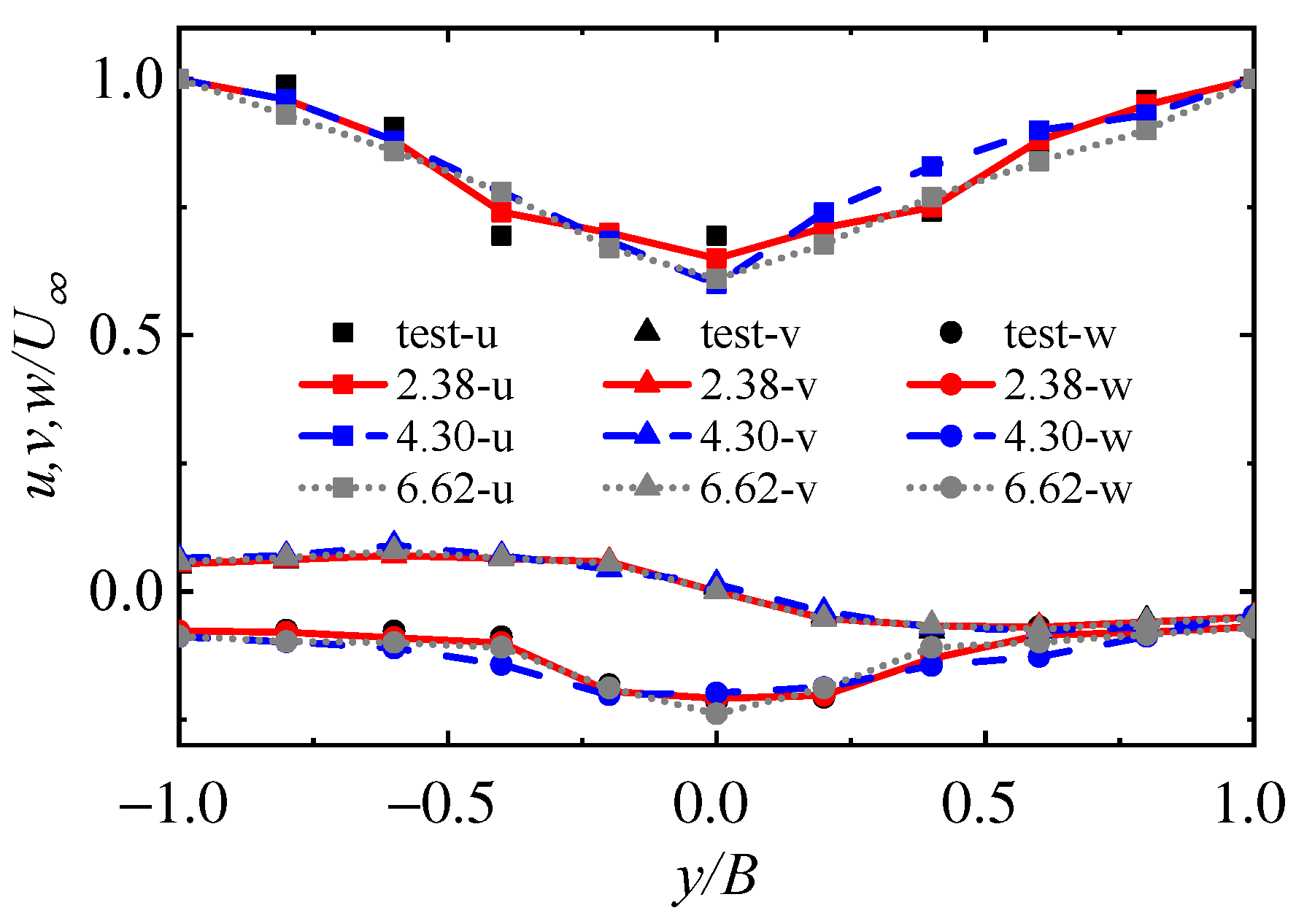
The simple frigate Shape 2 (SFS2) standard ship model data were applied to validate the ship airwake simulation method, and SFS2 was taken as the ship object in the following study. In the discussions to follow, the X-axis points from the bow to the stern, the Z-axis is perpendicular upwards to the deck, and the Y-axis is determined by the right-hand rule, as shown in Figure 2a. The deck width B and the hull width B h are 13.712 m, the hull length L h is 138.68 m, the deck length L is 27.43 m, the hull height H h is 16.77 m, and the hangar height H is 6.10 m. The mixed grid was divided by the ICEM software, and the study on grid sensitivity was carried out before further research. Three meshes have grid points numbering 2.38, 4.30, and 6.62 million, respectively. The WOD speed U is 15 m/s (about 30 knots) and 0 degrees. The 2.38 million grid details and the grid’s simulated contours of velocity magnitude at the plane of z / H = 1.0 are shown in Figure 2, and the computational domain is 12 L h (L) × 20 B h (W) × 10 H h (H). The results were compared with experiment data in the literature [32]. A monitor line was selected over and parallel to the deck; its length is 2 B , and the vertical projection is in the center of the deck. Figure 3 indicates the comparison of the predicted mean velocities of the monitor line, where y represents the distance from the point on the monitor line to the deck center, which is normalized by B ; u , v , and w represent the longitudinal, lateral, and vertical velocities, respectively, and are normalized by U . The velocity components calculated by the 2.38 million grid points basically agree with the literature experiment, and the results meet the research requirements of this paper as well as the efficiency requirements. Therefore, this mixed-meshing strategy was used in the following simulation.

2.3. Helicopter Flight Dynamics Model Coupled with Ship Airwake

The coupled model of helicopter flight dynamics model and ship airwake is key because there exists a complicated interaction between helicopter and ship airwake and a huge computation cost. In order to simplify the model complexity while capturing the influence of ship airwake on helicopter flight characteristics, only the interference of ship airwake on the helicopter is considered in the paper, and the temporal variation is ignored.
Ship airwake affects the aerodynamic force of each component mainly by changing their angle of incidence and, finally, affects the helicopter motion. The detailed procedures of flight dynamics model coupling with ship airwake are shown in the literature [33,34], and the helicopter flight dynamics modeling related to ship airwake is briefly described here.
According to the design parameters of the helicopter, the position coordinate R ¯ b s of each blade element about the ship coordinate system can be written as follows:
R ¯ bs = T g sh x sh y sh z sh + T g sh T b g x h y h z h + T g sh T b g T s b T r s 0 e 0 + T g sh T b g T s b T r s T bs r 0 r bs 0
where r bs is the distance from blade element to blade root; e is the hinge offset; x h , y h , z h T is the position of the hub; x c g , y c g , z c g T is the position of the center of gravity; T bs r is the coordinate transformation matrix (CTM) from the blade element coordinate system to the rotating shaft system; T r s is the CTM from the rotating shaft system to the nonrotating shaft system; T s b is the CTM from the nonrotating shaft system to the body axis system; T b g is the CTM from the body axis system to the ground axis system; T g s h is the CTM from the ground axis system to the ship coordinate system.
Based on the position coordinate R ¯ bs of each blade element, linear interpolation was performed on the intercepted three-dimensional space of the flowfield, and the airwake velocities of the blade element obtained by interpolation were converted to the blade element coordinate system as follows:
U T g U R g U P g = 1 Ω R T r bs T s r T b s T g b T sh g v xg v yg v zg
where v xg , v yg , and v zg are three velocity components of ship airwake; Ω and R are the rotational speed and radius of the main rotor; U T g , U R g , and U P g are the tangential, extensional, and vertical components of airwake velocity of blade element, respectively.
Considering the influence of ship airwake, the blade element motions, and induced velocities, the relative inflow velocity vector of any blade element can be expressed as follows:
V bs = U T i bs + U R j bs U P k bs
where i bs , j bs , and k bs are coordinate base vectors of the blade. Each component is as follows:
U T = 1 Ω R u s sin ψ + v s cos ψ ε Ω r s Ω + y 2 Ω r s Ω cos β + sin β p s cos ψ q s sin ψ + U T λ + U T g
U R = 1 Ω R u s cos β cos ψ v s cos β sin ψ + w s sin β + ε Ω sin β q s cos ψ + p s sin ψ + U R λ + U R g
U P = 1 Ω R u s sin β cos ψ + v s sin β sin ψ + w s cos β + ε Ω cos β q s cos ψ + p s sin ψ + y 2 Ω β ˙ + q s cos ψ + p s sin ψ + U P λ + U P g
where U T λ , U R λ , and U P λ are induced velocities; u s , v s , and w s are the three translational velocity components of the hub; p s , q s , and r s are the angular velocity components of the hub; ψ is blade phase angle; ε is the dimensionless length of the hinge offset; y 2 represents the dimensionless length from blade element to blade root; β and β ˙ are the blade-flapping angle and the angle rate. The angle of incidence, sideslip angle, and Mach number were obtained from the relative inflow velocity of each blade element. The lift coefficient and drag coefficient of the blade element were obtained by interpolation of the wind tunnel testing data, and then, the aerodynamic force of each blade element was calculated. Finally, the aerodynamic forces and moments of the whole main rotor were obtained.
In addition to affecting the aerodynamic forces of each blade, ship airwake also affects the induced velocity of the main rotor disk by changing the forward ratio, inflow ratio, and wake angle of the inflow on the disk. Considering the influence of ship airwake, hub motions, and induced velocities, the forward ratio μ , inflow ratio λ , and main rotor wake angle χ of the disk plane can be obtained as follows:
μ = μ xs μ xgs 2 + μ ys μ ygs 2
λ = v 0 μ zs + μ zgs
χ = tan 1 μ xs μ xgs λ + β 1 c
where μ xs , μ ys , and μ zs are the dimensionless velocity components of the hub; μ xgs , μ ygs , and μ zgs are the dimensionless airwake velocity components of the hub; v 0 is the mean value of the dimensionless induced velocity of the main rotor disk; β 1 c is the inclination angle of the main rotor blade tip. The main rotor forward ratio, inflow ratio, and wake angle mentioned above were substituted into the dynamic inflow model to calculate the main rotor induced velocity.
Ship airwake affects the fuselage, horizontal tail, vertical tail, or tail rotor similarly: The aerodynamic forces and moments change with the relative velocity of each component. The position coordinate R ¯ wf / ht / vt / tr of the fuselage, horizontal tail, vertical tail, and tail rotor in the ship coordinate system were obtained from the center of gravity position of the body and the design parameters of each helicopter component as follows:
R ¯ wf / ht / vt / tr = T g sh R x cg y cg z cg + T g sh T b g x wf / ht / vt / tr y wf / ht / vt / tr z wf / ht / vt / tr
where the subscript wf / ht / vt / tr represents the fuselage, horizontal tail, vertical tail, or tail rotor. Through interpolation, the airwake velocities of each helicopter component were converted to the body axis system as follows:
V ¯ gwf / ght / gvt / gtr = u gwf / ght / gvt / gtr v gwf / ght / gvt / gtr w gwf / ght / gvt / gtr = T g sh T b g v xg v yg v zg
The angle of incidence and sideslip angle can be obtained from the relative inflow velocity at the aerodynamic center of each component. The aerodynamic force and moment coefficients were obtained by interpolation of the wind tunnel testing data.
Eventually, the helicopter flight dynamics model considering the effects of ship airwake can be written as follows:
x ˙ = f ( x , u , w G , t )
where w G = w g   w gwf   w g h t   w g v t   w g t r T denotes the ship airwake velocity of each component of the helicopter, where w g = U T g V R g W P g i , j represents the airwake velocity of the j th element of the i th blade, and w gwf = u wf   v wf   w wf , w g h t = u ht   v ht   w ht , w g v t = u vt   v vt   w vt , and w g t r = u tr   v tr   w tr represent the airwake velocity components of the fuselage, the horizontal tail, the vertical tail, and the tail rotor, respectively.

3. Influence of Ship Airwake on Helicopter Shipboard Operations

3.1. Definition of Shipboard Operations

This study employed the abbreviations “S” and “P” to refer to the starboard and port side of the ship, respectively. The WOD speed U was set as 20 m/s (about 40 knots), which is a combination of ship and airwake velocity, and the angles of WOD are 0 (HD) as well as 15 and 45 degrees from the starboard (S15, S45) and the port side (P15, P45).
The helicopter landing data presented in this paper were analyzed in such a way that they relate to the standard U.K. Royal Navy landing approach technique as shown in Figure 4 [9]. A typical shipboard helicopter landing operation comprises a series of mission task elements (MTEs) as follows:
I.
Approach and deck-sides hover;
II.
Lateral translation;
III.
Station keeping over the deck;
IV.
Vertical descent to the landing spot.
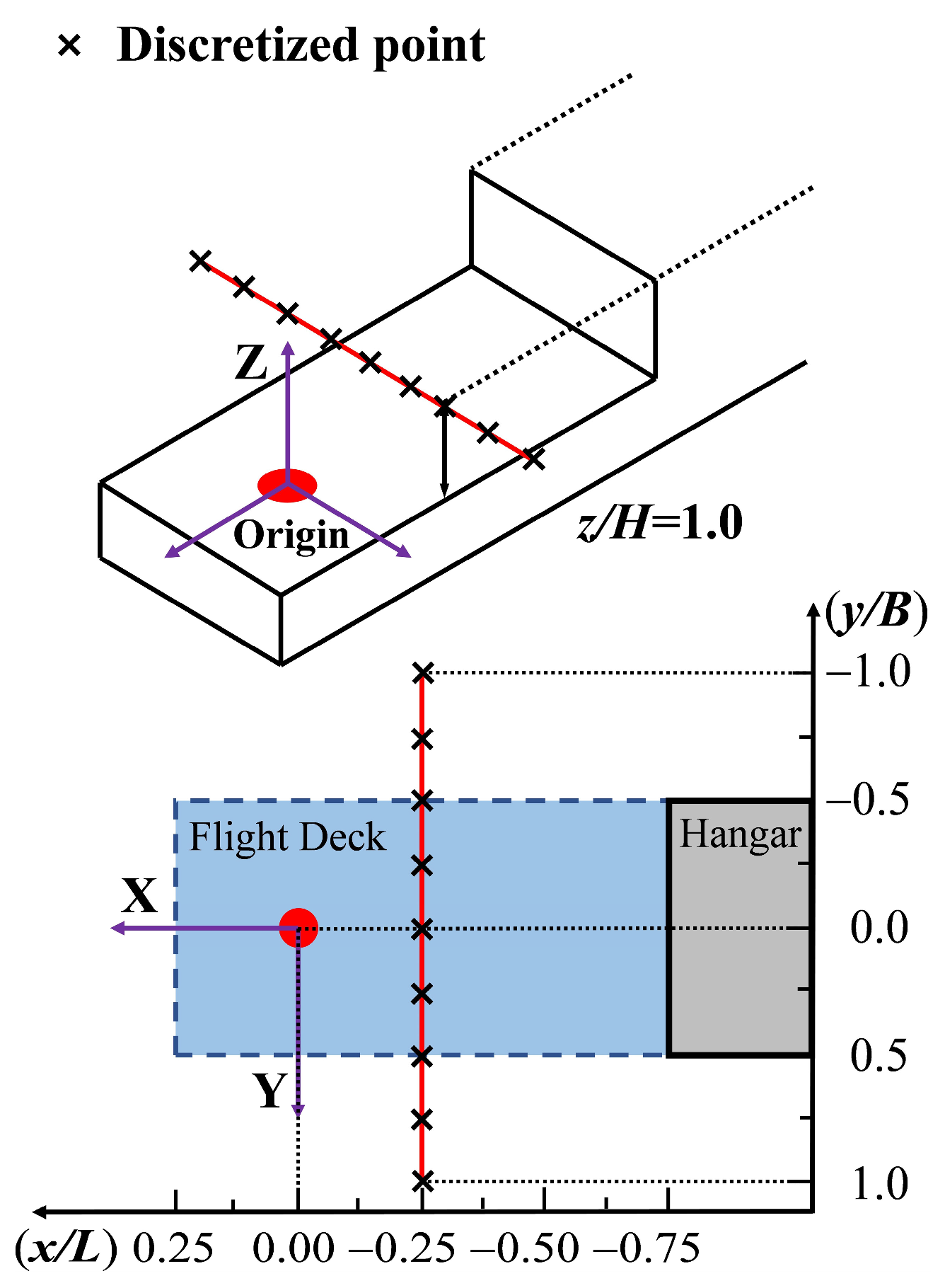
In the present work, a quasi-static (QS) approach was employed to evaluate the controls and attitudes of the helicopter for lateral translation in the operation scenario presented in Figure 4. The approach was discretized into a series of points along the lateral position of the deck. For each point, the helicopter was assumed in the trim condition for station keeping above the flight deck. Figure 5 shows the discretized points representing the movement of the center of gravity of the helicopter. These points are at the same height as the hangar above the landing spot located on the centerline of the ship at a longitudinal location halfway between the hangar face and the stern.

3.2. Influence on Flight Controls and Helicopter Attitudes in Shipboard Operations

Before exploring the influence of ship airwake on helicopter shipboard operations, this investigation tested the distribution of airwake (downwash and sidewash) at lateral positions in various angles of WOD to illustrate the variation of airwake caused by the change of WOD direction, providing theoretical support for the flow control strategy presented in this paper.
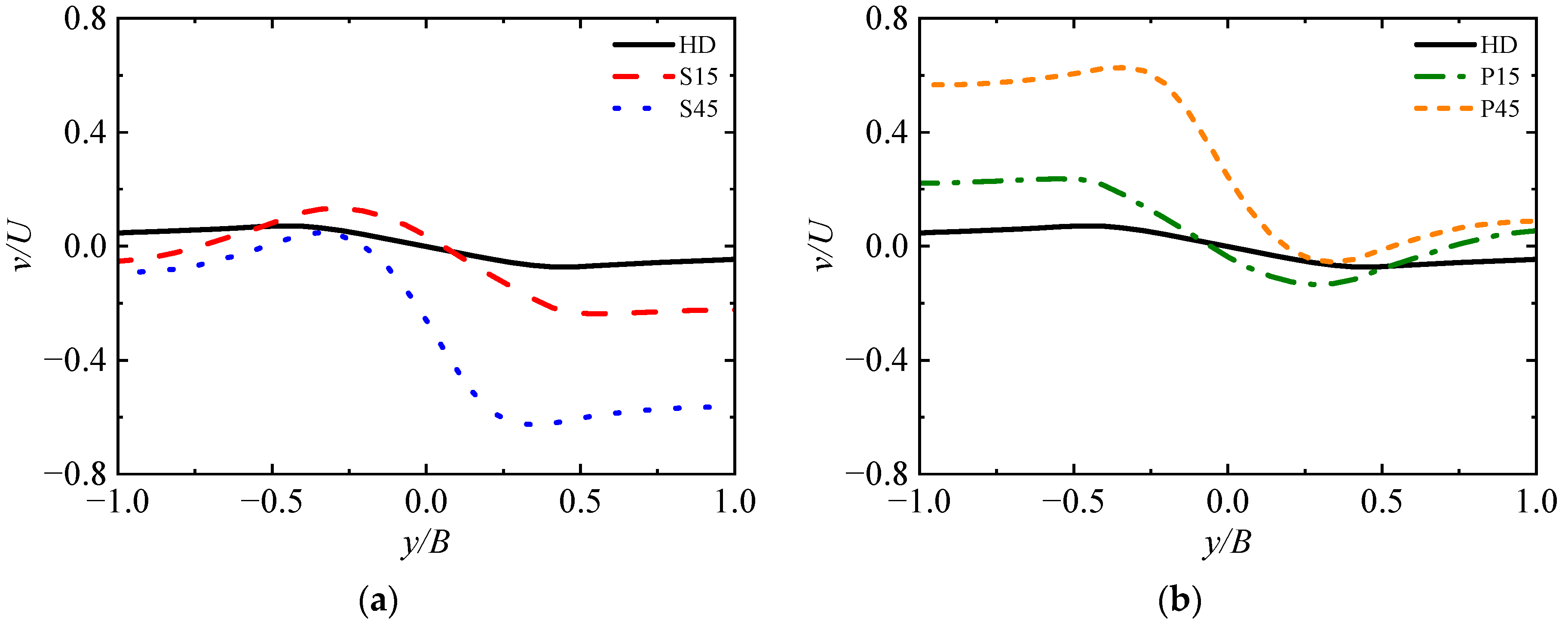
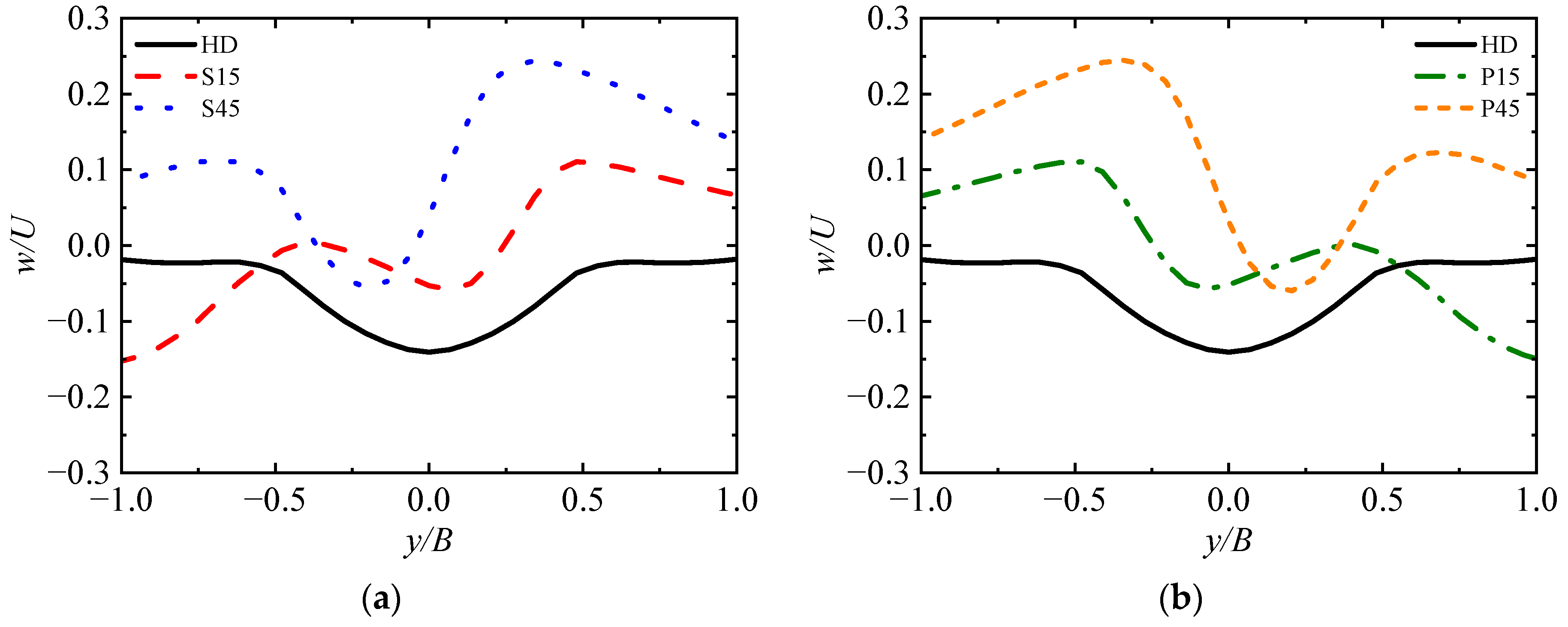
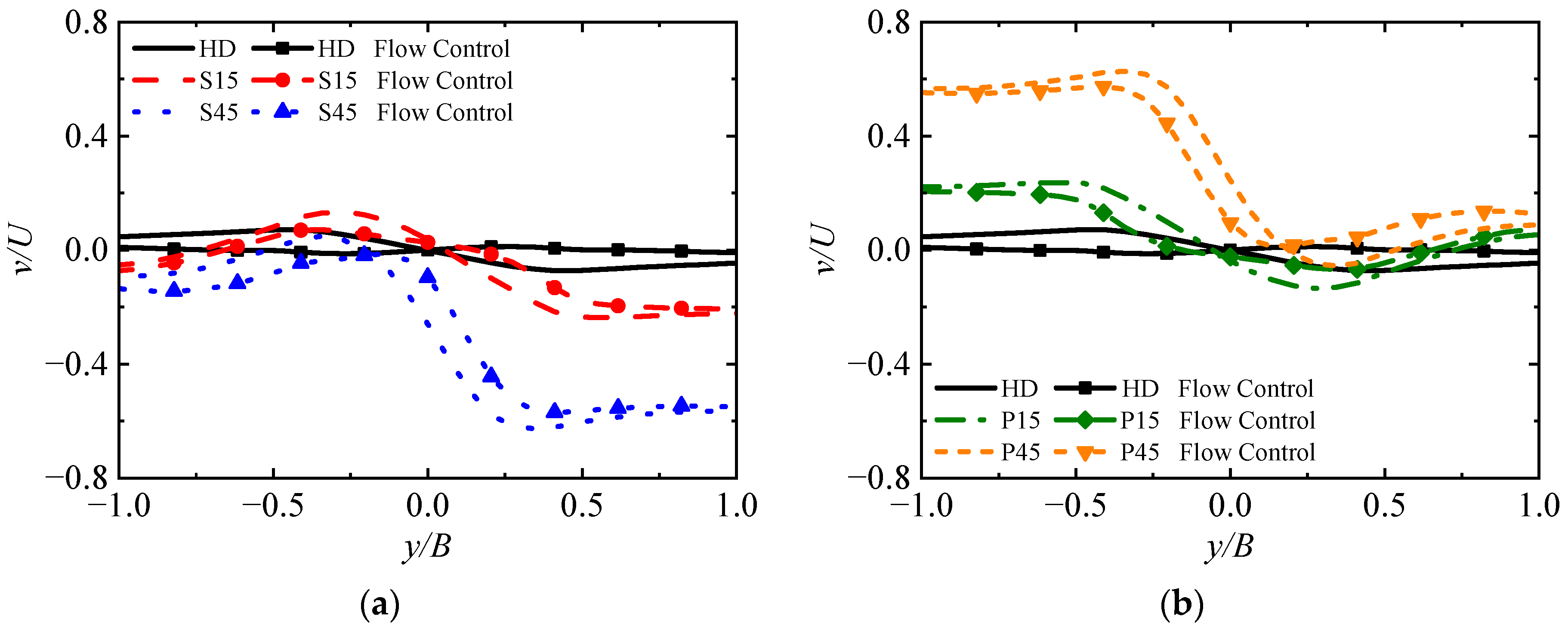
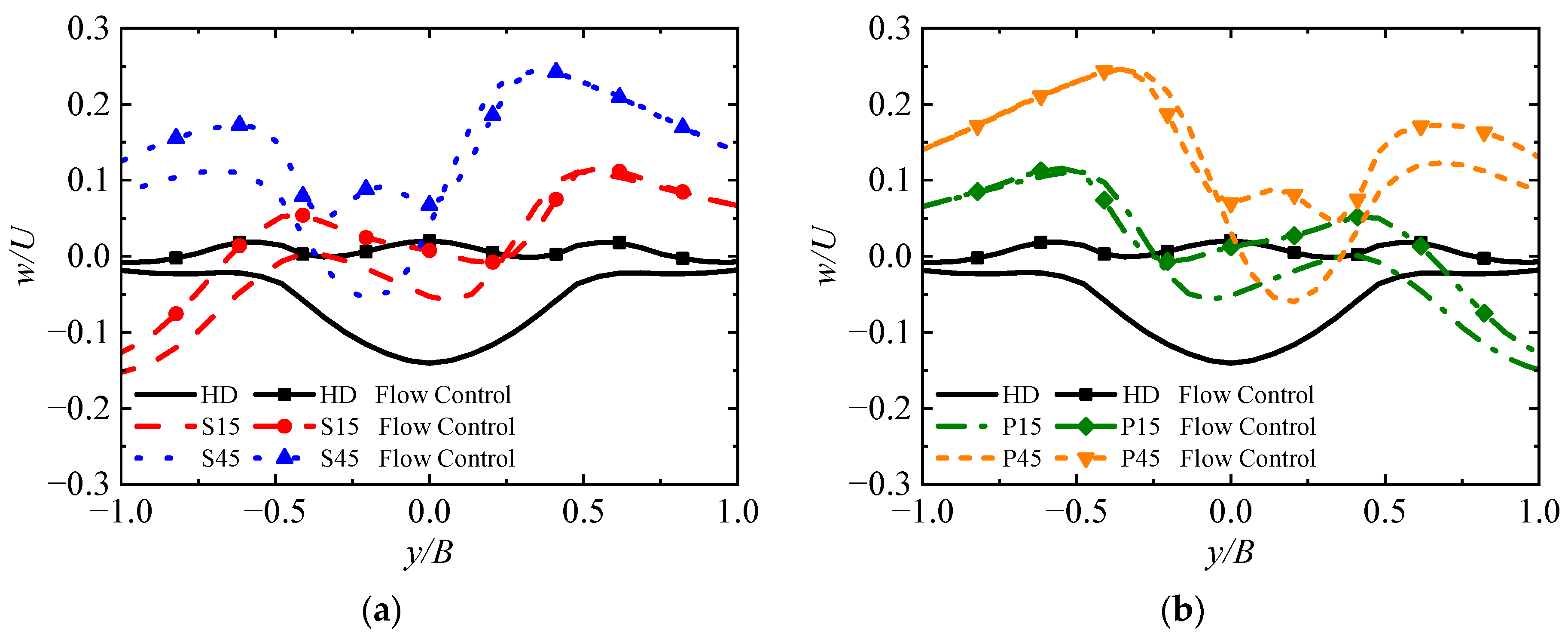
Figure 6 and Figure 7 depict the variations in the distribution of the sidewash and downwash for all WOD conditions. There is a considerable disparity in different angles of WOD, with the starboard WOD and port-side WOD conditions being significantly more nonuniform than the HD WOD condition.
The sidewash was asymmetrical, as shown in Figure 6. In the HD WOD condition, the directions of the sidewash on both the left and right sides of the deck were opposite. The sidewash on the right area of the deck grew as the angle of the starboard WOD increased, as shown in Figure 6a. When the angle of WOD was large enough, the direction of the sidewash in the landing zone gradually became consistent. These phenomena were caused by the separation of freestream through the two vertical edges of the hangar, forming lateral flow components with opposite directions. The sidewash component was dominated by crosswind as the angle of WOD increased. The situations of the port-side WOD were opposite.
The downwash of the ship airwake was similar to the flow over a backward-facing step [35], and the helicopter landing zone was located in the downwash of the recirculation region caused by the “steep wall effect”. Figure 7 shows that the downwash covered the entire landing zone in the HD WOD condition. With the increase of the angle of the starboard WOD, the nonuniformity of the downwash distribution became serious, with the downwash region moving to the left area of the deck as well as the upwash appearing in the right area. The situations of the port-side WOD were opposite.
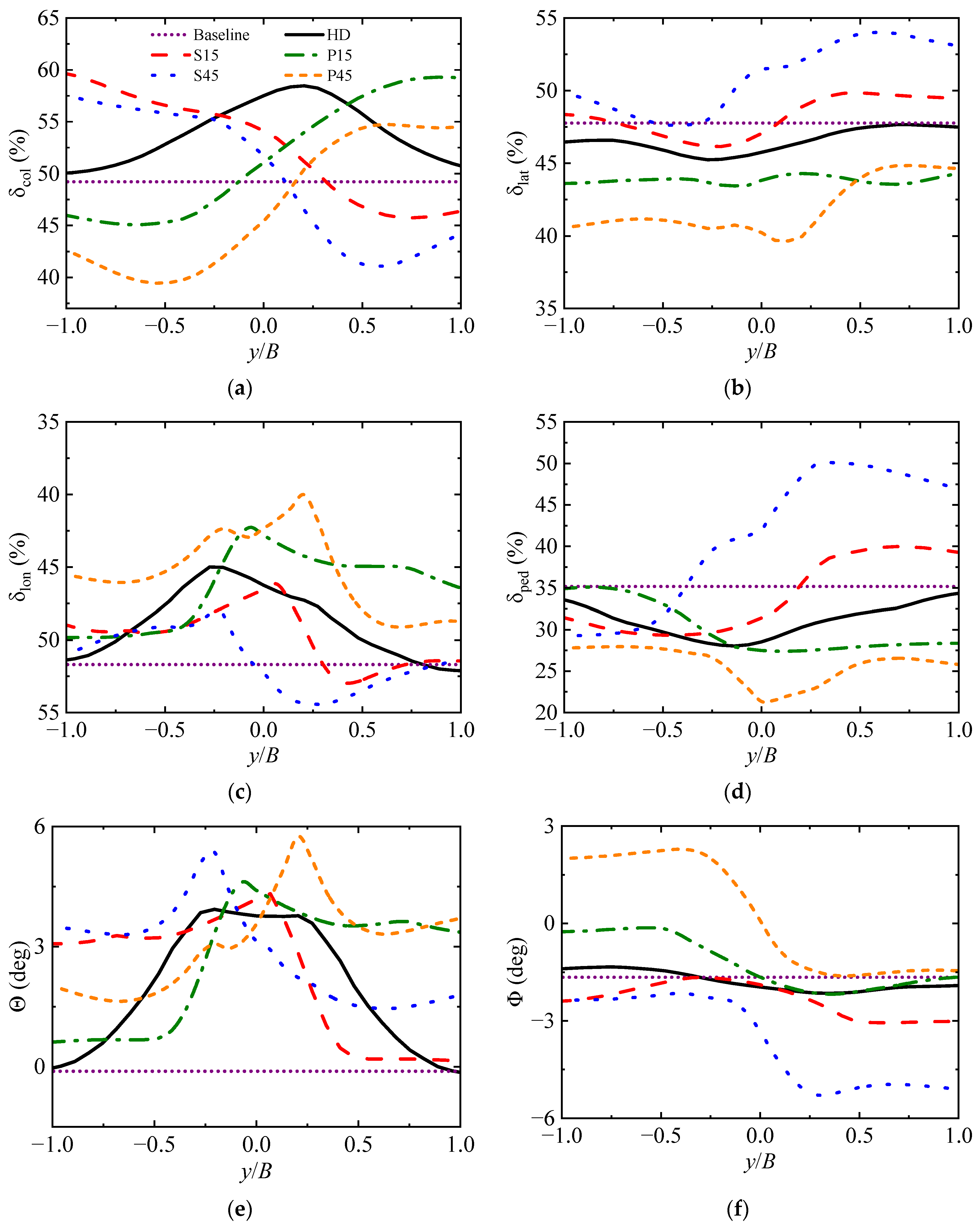
Figure 8 presents the influence of the airwake on flight controls and helicopter attitudes when the helicopter is in the relative hover condition with respect to the ship. We used the simulation results without airwake plotting by the “baseline” lines as the baseline condition for comparison. The controls are expressed as a percentage of control in the cockpit; for example, 0% of pedal control means that the pedals are completely left and 100% completely right. Flight controls and helicopter attitudes will not vary with the relative hover position when there is no airwake.
With airwake, the required collective pitch-stick input was increased as the helicopter flew closer to the landing spot, as shown in Figure 8a. At these hovering positions, the main rotor was immersed in the wake of the superstructure; particularly, the fore part of the rotor disk was significantly affected by the downwash due to the recirculation region. Because of the flow separation and accompanying components such as downwash, the relative inflow velocity of the main rotor was decreased, ultimately resulting in a reduction in its effective angle of attack. The pilot needed to pull up the collective pitch stick to increase the thrust of the main rotor to maintain the helicopter’s hovering, which ultimately brought a maximum reduction of 10.2% in the collective pitch-stick margin. When the helicopter encountered the starboard WOD in the left area of the deck, the downwash region moved to the left, requiring more collective pitch-stick input. However, at the same time, in the left deck area, the positive vertical component increased the effective angle of attack of the main rotor, and the collective pitch-stick input required was further reduced.
Figure 8b indicates the variation of the lateral-stick inputs due to the spatial distribution of the sidewash. For example, the pilot must bring the stick to the right to keep the body attitude against a trend to the left roll caused by the growth of the negative sidewash at the S15 WOD. The corresponding variation of the roll attitudes is shown in Figure 8f.
Figure 8d illustrates that the influence of the airwake on pedal controls is also of concern. The pilot needs to step on the left pedal approaching the landing spot, which makes the pedal travel progressively close to 0% and reduces the pedal margin. For the starboard crosswind condition, the pilot gradually releases the left pedal to maintain the head direction, which causes the pedal inputs to be more complicated.
As shown in Figure 8c, the longitudinal stick is now strongly forward around the position of the landing spot. The pilot must push the stick forward to keep the helicopter attitude against a trend to nose-up caused by the decrease in the relative velocity of the main rotor and the increase of pitch angle, as shown in Figure 8e. For the starboard crosswind condition, the helicopter does not need to maintain a large pitch attitude due to the increase in the relative velocity as well as the positive vertical component of the airwake, and the pilot can pull back the stick when operating in the right area of the deck.
These results evaluate the influence of ship airwake on helicopter shipboard operations under various angles of WOD. In general, the non-HD conditions are more challenging and require more pilot workload, which limits the helicopter to operate on the deck.

4. Active Flow Control for Helicopter Shipboard Operations

4.1. Design of Active Flow Control Strategy

The application of active flow controls on the deck is intended to weaken the adverse influence of the nonuniform and complex ship airwake on flight controls and helicopter attitudes. The energy input strategy of active flow control adopted is to change the boundary conditions of the deck; that is, a series of air-blowing holes were mounted on the deck to form a continuous air-blowing area, as shown in Figure 9.
The blowing velocity w b perpendicular to the deck was calculated by the following equation based on the mass flow rate m ˙ and the physical quantities (pressure, temperature, density, etc.) near it:
w b = m ˙ / ρ A
where A is the area, and the mass flow m ˙ is based on the Eulerian dispersed phase (EDP) principle.
The nonuniformity of the airwake distribution varies with different angles of WOD, as shown in Figure 6 and Figure 7. As a result, large variations of flight controls and helicopter attitudes are produced. Due to the inability of uniform blowing to capture different flow characteristics, a nonuniform blowing control strategy was developed in the paper. The control strategy is focused on weakening the downwash and causing less effect on the upwash in the plane of helicopter shipboard operation z / H = 1.0 . The detailed strategy is that the region of the downwash on the plane of z / H = 1.0 for each specific angle of WOD is mapped to the deck to determine the region of air blowing, while there is no air blowing in the other region of the deck. A two-dimensional polynomial expression for air blowing on the deck was constructed to satisfy the requirements of weakening the adverse effects on the flight controls and helicopter attitudes, as shown in Equation (17).
w ¯ b = c + f ( x ¯ ) + g ( y ¯ )
where x ¯ = x / L and y ¯ = y / B are normalized by the deck length L and deck width B , respectively; f and g are longitudinal and lateral positions functions of the deck; the blowing velocity w ¯ b = w b / U is normalized by U ; c is a constant term. The origin of the function coordinates is consistent with the origin of the ship coordinate system, as shown in Figure 5.
The polynomials f ( x ¯ ) and g ( y ¯ ) in Equation (17) were fitted with the Levenberg–Marquardt algorithm. With plenty of calculations, trade-off tests, and hand tuning and upon comparing the fitting index and the adjusted coefficients of determination R 2 of different polynomial orders under various angles of WOD, the final fifth-order polynomials f ( x ¯ ) and g ( y ¯ ) were determined with R 2 values greater than 0.8. Therefore, Equation (17) can be specifically expressed as Equations (18) to (22) for the region of interest of air blowing.
  • HD: c = 0.1005
    f ( x ¯ ) = 0.0964 x ¯ + 0.3454 x ¯ 2 0.0711 x ¯ 3 1.2981 x ¯ 4 + 1.3658 x ¯ 5 g ( y ¯ ) = 0.0024 y ¯ 0.5302 y ¯ 2 0.0033 y ¯ 3 + 0.3470 y ¯ 4 + 0.0479 y ¯ 5
  • S15: c = 0.0616
    f ( x ¯ ) = 0.1490 x ¯ + 0.3288 x ¯ 2 0.6039 x ¯ 3 2.0797 x ¯ 4 + 1.3303 x ¯ 5 g ( y ¯ ) = 0.2140 y ¯ 1.0256 y ¯ 2 4.9661 y ¯ 3 2.1426 y ¯ 4 + 16.5395 y ¯ 5
  • S45:   c = 0.0719
    f ( x ¯ ) = 0.0902 x ¯ + 0.2824 x ¯ 2 1.1399 x ¯ 3 3.5570 x ¯ 4 0.6144 x ¯ 5 g ( y ¯ ) = 0.4191 y ¯ + 0.6356 y ¯ 2 + 7.5596 y ¯ 3 26.0561 y ¯ 4 84.9636 y ¯ 5
  • P15: c = 0.0607
    f ( x ¯ ) = 0.1542 x + 0.4068 x 2 0.4609 x 3 2.8397 x 4 0.0937 x 5 g ( y ¯ ) = 0.1995 y 1.0247 y 2 + 4.2874 y 3 1.8234 y 4 9.8812 y 5
  • P45: c = 0.0776
    f ( x ¯ ) = 0.0959 x ¯ + 0.1458 x ¯ 2 1.0808 x ¯ 3 2.2636 x ¯ 4 + 0.8443 x ¯ 5 g ( y ¯ ) = 0.4120 y ¯ + 0.3056 y ¯ 2 7.3721 y ¯ 3 19.1961 y ¯ 4 + 71.2756 y ¯ 5
It is worth noting that Equations (18)–(22) can adjust the air blowing on the specified region of the deck for different angles of WOD. Figure 10 shows the air blowing for HD and P45 WOD.
Figure 11 and Figure 12 compare the variations in the distribution of the sidewash and downwash for all WOD conditions, respectively. They were obtained with the CFD numerical simulation of ship airwake together with blowing control. During the simulation, the boundary conditions of the deck were modified from the wall to the velocity inlet. The blowing equations were compiled into the user-defined function (UDF) code to define the velocity inlet conditions, thereby implementing blowing control.
To illustrate the effect of blowing intuitively, Figure 13 shows the contours of mean downwash at the plane of z / H = 1.0 in the HD WOD condition without and with the active flow control. It can be found in Figure 11 that the positive and negative sidewash values on both sides of the deck have a trend toward zero, and the values in the HD WOD condition are nearly the same. As the angle of WOD increases, the more serious the nonuniformity, and the better the control effect. However, for the whole lateral components generated by the crosswind, the control effect weakens as the angle of WOD increases. Figure 12 and Figure 13 indicate that the complexity of the downwash in the deck disappears with the active blowing regardless of the variations in the angle of WOD.
The blowing control strategy used in this paper can improve the uniformity of the downwash flow under various angles of WOD. As the energy is replenished to the ship airwake by the active flow control, the upward flow generated is fused with the downwash to form a new flow, weakening the nonuniformity of the downwash in a different airwake. At the same time, part of the sidewash is blown away.

4.2. Influence on Flight Controls and Helicopter Attitudes

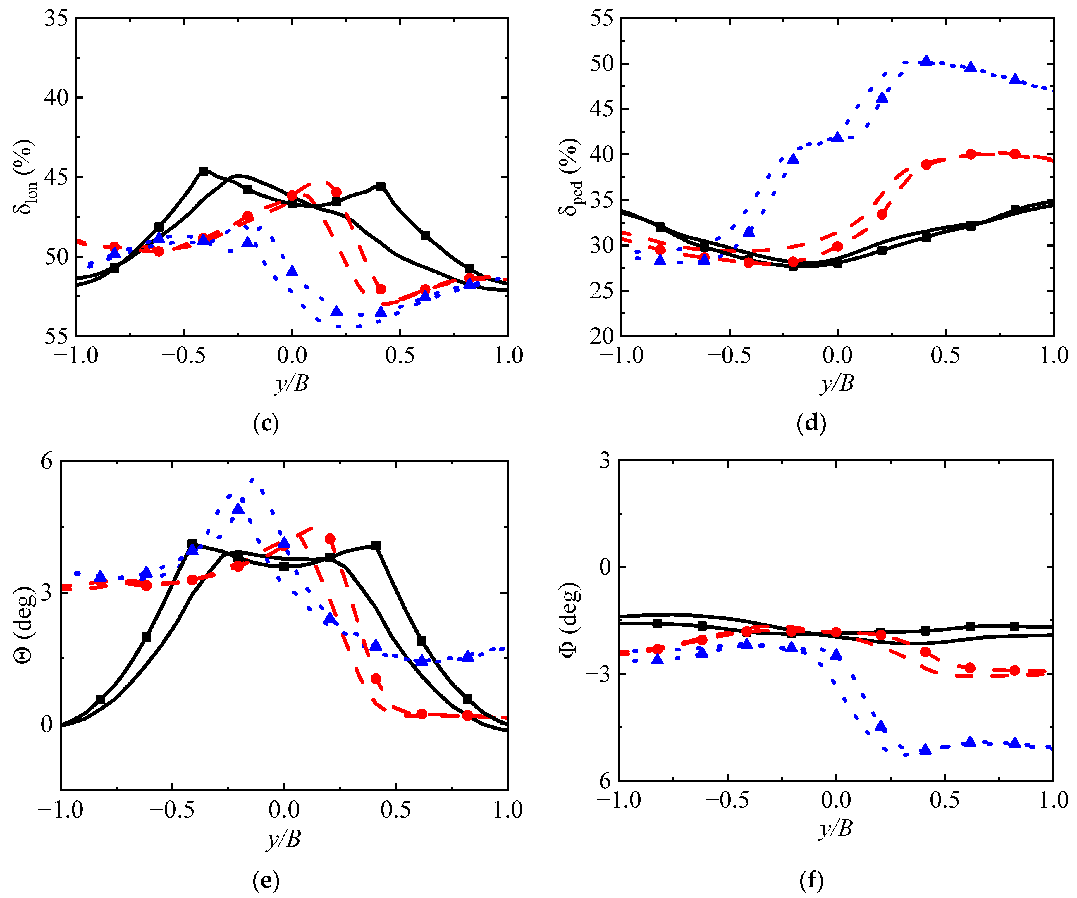
The variations in the angle of WOD affect the spatial distribution of the flow pattern in the landing zone and, finally, affect flight controls and helicopter attitudes in the relative hover condition. It becomes more difficult for the pilot to adjust the control inputs to maintain helicopter attitudes to prevent deviation from the position of lateral translation under larger angles of WOD. Figure 14 and Figure 15 show the variations of flight controls and helicopter attitudes with the active flow control in the starboard and port-side WOD conditions, respectively.
With active flow control, the maximum control margins of the collective pitch-stick input in the HD WOD condition, the lateral-stick input, the longitudinal-stick input, and the pedal input in the P45 WOD condition increased by 2.2%, 1.9%, 2.4%, and 1.3%, respectively. Although these increments are not significant in their respective whole stick, the effectiveness of the active flow control was demonstrated compared with the values without flow control. There are obvious control effects on the roll attitude angles. The amplitude of roll angle in the HD, S15, S45, P15, and P45 WOD conditions decreased by 65.1%, 18.5%, 6.5%, 18.5%, and 4.5%, respectively. The control effect on the pitch angles is not as obvious as the roll angles.
The comparison of all angles of WOD shows that the active blowing consistently improves the ship airwake uniformity regardless of the WOD conditions. According to the analysis, the main effect of the active flow control on the downwash is to weaken its intensity and nonuniformity. The weakening of the downwash means an increase in the effective angle of attack for the rotor disk, so the pilot no longer has to pull up the collective pitch stick excessively, and the control margin increases accordingly. However, the improvement of vertical flow replenishment generated by the active flow control cannot cope with the dominant role of the relative inflow of the main rotor under larger angles of WOD.
The asymmetrical sidewash in the horizontal recirculation region has always existed. After being actively controlled and blown away, the reduction of the sidewash component in the freestream cuts down the roll amplitude of the helicopter, so the pilot does not need to spend more energy on dealing with the lateral stick. According to the influence of the sidewash obtained by previous analysis, Figure 15b,f indicate that as the angle of WOD increases, the control effect has a better improvement effect on the lateral stick and roll angle, especially in the port-side WOD conditions. However, the effect is still limited by the dominant role of the crosswind as the relative inflow.
In some crosswind conditions, the airwake has little influence on the leeward regions. At this time, the active blowing can still increase the effective angle of attack of the disk and slow down the trend of the helicopter to nose-up. Therefore, in these zones, the control margins of the longitudinal-stick inputs are increased due to the pilot pulling back the longitudinal stick.
Although the active blowing can blow away part of the sidewash, when the sidewash gradually becomes the main factor to the main rotor, the active flow control cannot inhibit the variations of the pedal; therefore, the pedal margin as well as its trend are almost unchanged.

5. Conclusions

In this research, a numerical method coupling numerical simulation and a flight dynamic model was developed to investigate the effect of active flow control of ship airwake on a helicopter during landing tasks. The following conclusions can be drawn based on the findings:
  • The flow over the landing deck of a frigate is nonuniform and complex, which makes it more hazardous for helicopter shipboard operations than without airwake. The dilemma is made worse by the variation of the angles of WOD. By reducing control margins and increasing pilot workload, the airwake distribution brought on by large angles of WOD limits helicopter shipboard operations;
  • Active flow control was applied by continuous nonuniform blowing on the deck. The control strategies matched the key flow characteristics, and the asymmetry of the sidewash distribution as well as the nonuniformity of the downwash distribution were weakened. In parallel, the majority of control margins were increased in the lateral translation task of helicopter shipboard operations, and the variations of flight control inputs and helicopter attitude angles were reduced, which contributes to improving the safety of shipboard operations. Nevertheless, under large angles of WOD, variations such as the helicopter pitch attitudes are beyond the control capability achieved by the active flow control strategy presented in this paper. How to effectively address the limitations of the control strategy is the next problem to be tackled;
  • Based on the active flow control strategy presented in this paper, for the UH-60A helicopter, the landing approach can be conducted from the starboard to the landing spot when the direction of WOD is from the port side, while the landing approach is conducted from the port side to the landing spot if the direction of WOD is from the starboard.

6. Future Works

Before landing on the deck, helicopters will maintain relative hovering above the ship and wait for a suitable opportunity to land. Therefore, using “one-way coupling” (in which the ship airwake is computed independently from the helicopter wake) to study the static trim characteristics of helicopters at each position in the ship airwake has a good reference value for analyzing the control margin during helicopter landing. In future research, further consideration can be given to “two-way coupling” (in which the ship and helicopter airwakes are both dependent on each other and computed simultaneously) and more precise dynamic response characteristics during landing.
To obtain insight into the average ship airwake field characteristics over the deck and show the effect of active flow control more accurately, the steady RANS approach used in this paper is beneficial and economical for performing a large number of numerical simulations. Furthermore, the choice of the computationally more intensive unsteady method would be better for capturing fluctuating flowfield characteristics such as vortex shedding or turbulence as well as to improve the precision of the simulation of helicopter shipboard operations.

Author Contributions

Conceptualization, Y.Y. and R.C.; methodology, Y.Y. and H.J.; software, Y.Y.; validation, Y.Y. and H.J.; formal analysis, Y.Y.; investigation, Y.Y.; resources, Y.Y.; data curation, Y.Y.; writing—original draft preparation, Y.Y.; writing—review and editing, R.C.; visualization, Y.Y.; supervision, R.C.; project administration, R.C.; funding acquisition, R.C. All authors have read and agreed to the published version of the manuscript.

Funding

This research was supported by the National Natural Science Foundation of China, NO: 11902052.

Data Availability Statement

The data presented in this study are available on request from the corresponding author. The data are not publicly available due to privacy or ethical restrictions.

Conflicts of Interest

The authors declare no conflicts of interest.

References

  1. Reddy, K.R.; Toffoletto, R.; Jones, K.R.W. Numerical Simulation of Ship Airwake. Comput. Fluids 2000, 29, 451–465. [Google Scholar] [CrossRef]
  2. Polsky, S.; Bruner, C. Time-Accurate Computational Simulations of an LHA Ship Airwake. In Proceedings of the 18th Applied Aerodynamics Conference, Denver, CO, USA, 14–17 August 2000; American Institute of Aeronautics and Astronautics: Denver, CO, USA, 2000. AIAA 2000-4126. [Google Scholar]
  3. Forrest, J.S.; Owen, I. An Investigation of Ship Airwakes Using Detached-Eddy Simulation. Comput. Fluids 2010, 39, 656–673. [Google Scholar] [CrossRef]
  4. Polsky, S. A Computational Study of Unsteady Ship Airwake. In Proceedings of the 40th AIAA Aerospace Sciences Meeting & Exhibit, Reno, NV, USA, 14–17 January 2002; American Institute of Aeronautics and Astronautics: Reno, NV, USA, 2002. AIAA 2002-1022. [Google Scholar]
  5. Polsky, S. CFD Prediction of Airwake Flowfields for Ships Experiencing Beam Winds. In Proceedings of the 21st AIAA Applied Aerodynamics Conference, Orlando, FL, USA, 23–26 June 2003; American Institute of Aeronautics and Astronautics: Orlando, FL, USA, 2003. AIAA 2003-3657. [Google Scholar]
  6. Buonaccorso, J.A.; Widman, S.J.; Miklosovic, D.S. Pressure Field Mapping of a Modified YP Craft Flight Deck. In Proceedings of the AIAA Centennial of Naval Aviation Forum “100 Years of Achievement and Progress”, Virginia Beach, VA, USA, 21–22 September 2011; American Institute of Aeronautics and Astronautics: Virginia Beach, VA, USA, 2011. AIAA 2011-7044. [Google Scholar]
  7. Nacakli, Y.; Landman, D.; Doane, S. Investigation of Backward-Facing-Step Flow Field for Dynamic Interface Application. J. Am. Helicopter Soc. 2012, 57, 1–9. [Google Scholar] [CrossRef]
  8. Scott, P.; Kelly, M.F.; White, M.D.; Owen, I. Using Piloted Simulation to Measure Pilot Workload of Landing a Helicopter on a Smal Ship. In Proceedings of the 43rd European Rotorcraft Forum, Milan, Italy, 12–15 September 2017. [Google Scholar]
  9. Kääriä, C.H.; Forrest, J.S.; Owen, I. The Virtual AirDyn: A Simulation Technique for Evaluating the Aerodynamic Impact of Ship Superstructures on Helicopter Operations. Aeronaut. J. 2013, 117, 1233–1248. [Google Scholar] [CrossRef]
  10. Hoencamp, A.; Pavel, M.D. Concept of a Predictive Tool for Ship–Helicopter Operational Limitations of Various In-Service Conditions. J. Am. Helicopter Soc. 2012, 57, 1–9. [Google Scholar] [CrossRef]
  11. Forrest, J.S.; Owen, I.; Padfield, G.D.; Hodge, S.J. Ship-Helicopter Operating Limits Prediction Using Piloted Flight Simulation and Time-Accurate Airwakes. J. Aircr. 2012, 49, 1020–1031. [Google Scholar] [CrossRef]
  12. Findlay, D.; Ghee, T. Experimental Investigation of Ship Airwake Flow Control for a US Navy Flight II-A Class Destroyer (DDG). In Proceedings of the 3rd AIAA Flow Control Conference, San Francisco, CA, USA, 5–8 June 2006; American Institute of Aeronautics and Astronautics: San Francisco, CA, USA, 2006. AIAA 2006-3501. [Google Scholar]
  13. Duy, T.N.; Hino, T.; Suzuki, K. Numerical Study on Stern Flow Fields of Ship Hulls with Different Transom Configurations. Ocean Eng. 2017, 129, 401–414. [Google Scholar] [CrossRef]
  14. Kaeaeriae, C.H.; Wang, Y.; White, M.D.; Owen, I. An Experimental Technique for Evaluating the Aerodynamic Impact of Ship Superstructures on Helicopter Operations. Ocean Eng. 2013, 61, 97–108. [Google Scholar] [CrossRef]
  15. Lasalle, N.R. Study of Passive Flow Control for Ship Air Wakes; USNA-TSPR-418; Defense Technical Information Center: Fort Belvoir, VA, USA, 2013.
  16. Shi, Y.; He, X.; Xu, Y.; Xu, G. Numerical Study on Flow Control of Ship Airwake and Rotor Airload during Helicopter Shipboard Landing. Chin. J. Aeronaut. 2019, 32, 324–336. [Google Scholar] [CrossRef]
  17. Forrest, J.S.; Kaaria, C.H.; Owen, I. Determining the Impact of HangarEdge Modifications on Ship-Helicopter Operations Using Offline and Piloted Helicopter Flight Simulation. In Proceedings of the American Helicopter Society 66th Annual Forum & Technology Display, VFS, Phoenix, AZ, USA, 11–13 May 2010. [Google Scholar]
  18. Shafer, D.; Ghee, T. Active and Passive Flow Control over the Flight Deck of Small Naval Vessels. In Proceedings of the 35th AIAA Fluid Dynamics Conference and Exhibit, Toronto, ON, Canada, 6–9 June 2005; American Institute of Aeronautics and Astronautics: Toronto, ON, Canada, 2005. AIAA 2005-5265. [Google Scholar]
  19. Shi, Y.; Su, D.; Xu, G. Numerical Investigation of the Influence of Passive/Active Flow Control on Ship/Helicopter Dynamic Interface. Aerosp. Sci. Technol. 2020, 106, 106205. [Google Scholar] [CrossRef]
  20. Matías-García, J.C.; Bardera, R.; Franchini, S.; Barderas, E.B. Experimental Comparison of Flow Control Techniques on Helicopter Flight Deck of Frigates. In Proceedings of the AIAA AVIATION 2023 Forum, San Diego, CA, USA, 12–16 June 2023; American Institute of Aeronautics and Astronautics: San Diego, CA, USA, 2023. AIAA 2023-4207. [Google Scholar]
  21. Matías-García, J.C.; Bardera, R.; Barroso, E.; Franchini, S. Improvement of Helicopter Operations on Frigates Using the Coanda Effect. J. Aircr. 2023, 60, 1626–1637. [Google Scholar] [CrossRef]
  22. Bardera-Mora, R.; Conesa, A.; Lozano, I. Simple Frigate Shape Plasma Flow Control. Proc. Inst. Mech. Eng. Part G J. Aerosp. Eng. 2016, 230, 2693–2699. [Google Scholar] [CrossRef]
  23. Howlett, J.J. UH-60A Black Hawk Engineering Simulation Program; NASA-CR-166309; NASA Ames Research Center: Moffett Field, CA, USA, 1981.
  24. Li, P.; Chen, R. A Mathematical Model for Helicopter Comprehensive Analysis. Chin. J. Aeronaut. 2010, 23, 320–326. [Google Scholar]
  25. Chen, R.; Yuan, Y.; Thomson, D. A Review of Mathematical Modelling Techniques for Advanced Rotorcraft Configurations. Prog. Aerosp. Sci. 2021, 120, 100681. [Google Scholar] [CrossRef]
  26. Yuan, Y.; Thomson, D.; Anderson, D. Aerodynamic Uncertainty Quantification for Tiltrotor Aircraft. Aerospace 2022, 9, 271. [Google Scholar] [CrossRef]
  27. Pitt, D.M.; Peters, D.A. Theoretical Prediction of Dynamic Inflow Derivatives. Vertica 1981, 5, 21–34. [Google Scholar]
  28. Peters, D.A.; Haquang, N. Dynamic Inflow for Practical Applications. J. Am. Helicopter Soc. 1988, 33, 64–68. [Google Scholar] [CrossRef]
  29. Bailey, F.J. A Simplified Theoretical Method of Determining the Characteristics of a Lifting Rotor in Forward Flight; NASA-TR-716; NACA Langley Memorial Aeronautical Laboratory: Langley Field, VA, USA, 1941. [Google Scholar]
  30. Ballin, M.G. Validation of a Real-Time Engineering Simulation of the UH-60A Helicopter; NASA-TM-88360; NASA Ames Research Center: Moffett Field, CA, USA, 1987.
  31. Syms, G.F. Numerical Simulation of Frigate Airwakes. Int. J. Comput. Fluid Dyn. 2004, 18, 199–207. [Google Scholar] [CrossRef]
  32. Zhang, F.; Xu, H.; Ball, N. Numerical Simulation of Unsteady Flow over SFS 2 Ship Model. In Proceedings of the 47th AIAA Aerospace Sciences Meeting Including The New Horizons Forum and Aerospace Exposition, Orlando, FL, USA, 5–8 January 2009; American Institute of Aeronautics and Astronautics: Orlando, FL, USA, 2009. AIAA 2009-81. [Google Scholar]
  33. Ji, H.; Chen, R.; Li, P. Rotor-State Feedback Control to Alleviate Pilot Workload for Helicopter Shipboard Operations. J. Guid. Control Dyn. 2017, 40, 3088–3099. [Google Scholar] [CrossRef]
  34. Ji, H.; Chen, R.; Li, P. Real-Time Simulation Model for Helicopter Flight Task Analysis in Turbulent Atmospheric Environment. Aerosp. Sci. Technol. 2019, 92, 289–299. [Google Scholar] [CrossRef]
  35. Kang, S.; Choi, H. Suboptimal Feedback Control of Turbulent Flow over a Backward-Facing Step. J. Fluid Mech. 2002, 463, 201–227. [Google Scholar] [CrossRef]
Figure 1. The control inputs and attitudes of the UH-60A in steady flight. (a) Collective pitch stick; (b) lateral stick; (c) longitudinal stick; (d) pedal position; (e) pitch angle; (f) roll angle.
Aerospace 11 00119 g001aAerospace 11 00119 g001b
Figure 2. Schematic of SFS2. (a) Grid details; (b) contours of velocity magnitude at the plane of z / H = 1.0 under 0 degrees WOD.
Aerospace 11 00119 g002
Figure 3. Mean velocities.
Aerospace 11 00119 g003
Figure 4. The schematic of the Standard Royal Navy Landing Approach Technique.
Aerospace 11 00119 g004
Figure 5. The discretized points of the landing approach.
Aerospace 11 00119 g005
Figure 6. Variations of the distribution of the sidewash. (a) HD and starboard; (b) HD and port side.
Aerospace 11 00119 g006
Figure 7. Variations of the distribution of the downwash. (a) HD and starboard; (b) HD and port side.
Aerospace 11 00119 g007
Figure 8. Variations of flight controls and helicopter attitudes compared to the baseline. (a) Collective pitch stick; (b) lateral stick; (c) longitudinal stick; (d) pedal position; (e) pitch angle; (f) roll angle.
Aerospace 11 00119 g008
Figure 9. Schematic of the active blowing.
Aerospace 11 00119 g009
Figure 10. Nonuniform blowing on the deck. (a) HD; (b) P45.
Aerospace 11 00119 g010
Figure 11. Variations of the distribution of the sidewash with flow control. (a) HD and starboard; (b) HD and port side.
Aerospace 11 00119 g011
Figure 12. Variations of the distribution of the downwash with flow control. (a) HD and starboard; (b) HD and port side.
Aerospace 11 00119 g012
Figure 13. Contours of mean downwash at the plane of z / H = 1.0 in the HD condition. (a) Without flow control; (b) with flow control.
Aerospace 11 00119 g013
Figure 14. Variations of flight controls and helicopter attitudes in the starboard WOD conditions with flow control. (a) Collective pitch stick; (b) lateral stick; (c) longitudinal stick; (d) pedal position; (e) pitch angle; (f) roll angle.
Aerospace 11 00119 g014aAerospace 11 00119 g014b
Figure 15. Variations of flight controls and helicopter attitudes in the port-side WOD conditions with flow control. (a) Collective pitch stick; (b) lateral stick; (c) longitudinal stick; (d) pedal position; (e) pitch angle; (f) roll angle.
Aerospace 11 00119 g015aAerospace 11 00119 g015b
Disclaimer/Publisher’s Note: The statements, opinions and data contained in all publications are solely those of the individual author(s) and contributor(s) and not of MDPI and/or the editor(s). MDPI and/or the editor(s) disclaim responsibility for any injury to people or property resulting from any ideas, methods, instructions or products referred to in the content.