1. Introduction
With the continuous improvement of functionality and performance requirements in aerospace engineering, large-scale and flexible spacecraft structures have become increasingly important [
1,
2,
3]. This trend is reflected in the wide applications of large flexible space structures (LFSSs) with additional functionality and improved performance, such as larger solar panels generating more energy. China’s major space projects, such as manned spaceflight, lunar exploration, and high-resolution earth observation systems, also urgently need large space structures of 10 to 100 m in size [
4]. However, this also brings design and manufacturing challenges, such as the higher geometric and temporal resolution requirements of remote sensing equipment and the strict control accuracy requirements of increasingly complex space observation systems [
5,
6,
7,
8]. In addition, satellites with large moving parts and large, lightweight, flexible structures have higher mission requirements for attitude stability and vibration suppression accuracy [
9]. On-orbit control and service technology for large space structures is an important research direction in modern space science and technology [
10,
11].
Large space ring structures, as a special type of LFSS, are becoming increasingly important in modern aerospace engineering [
12,
13,
14]. Their unique geometric shape and mechanical properties give them significant advantages in providing large-aperture, high-precision communication and observation capabilities. These structures can effectively increase the receiving area of antennas, thereby improving signal reception quality to meet the needs of modern aerospace missions for high-performance communication and observation [
15]. Additionally, the design flexibility of large space ring structures allows them to adapt to different mission requirements and environmental conditions. Therefore, the research and application of large space ring structures are receiving more and more attention and importance in modern aerospace engineering.
Managing space structure dynamics is one of the key technological aspects of large spacecraft operations. Due to their considerable size complexity, these spacecrafts often boast enhanced flexibility that renders them vulnerable to disturbances from their operational environment. This susceptibility negatively affects their stability and pointing accuracy, thus posing significant challenges for on-orbit control. To tackle these complexities, researchers worldwide have investigated thoroughly the dynamics control of large space structures and relevant control mechanisms. Previous studies [
16,
17,
18] have designed computationally efficient control strategies to facilitate attitude tracking under varying conditions while reducing energy consumption. Researchers [
19] utilized finite Fourier series shapes to create three-dimensional trajectories within obstacle environments, effectively producing time-optimal paths adhering to obstacle avoidance constraints dictated by attitude dynamics. Additionally, Shi et al. [
20] developed a simplified model incorporating electromagnetic force/torque interactions alongside an orbital–attitude coupled dynamic framework pertinent during electromagnetic docking scenarios. They also proposed an enhanced sliding mode control strategy based on pre-defined trajectory pathways.
With the increasing complexity and flexibility of large space structures, the demand for attitude and shape control is growing. Lasemi et al. [
21] proposed a trajectory planning method based on critical safety curves to address the impact of shape during spacecraft docking, resulting in safe, smooth, and easily trackable trajectories. Wang et al. [
22] introduced an autonomous collaborative control method for attitude and momentum based on zero-space adaptive planning, targeting rapidly changing and strong disturbances produced by jetting and component movements. Gong et al. [
23] employed an active disturbance rejection controller to estimate and compensate for satellite attitude disturbances caused by solar panel aligning and system uncertainties. Methods such as the finite-time attitude control based on the super-twisting disturbance observer in [
24] can achieve the stable shape control of large spacecrafts under a wide range of dynamics uncertainties. Santiago J et al. [
25] addressed the impact of collision disturbances on the overall attitude and shape during spacecraft docking and proposed a double-integral sliding mode control method based on reaction wheel reconstruction. Despite significant progress in the attitude control, orbit modification, and shape control of spacecrafts, the dynamics and control issues of large space structures in coupled attitude–orbit–shape scenarios still require further research and resolution.
The coupled attitude–orbit–shape dynamic modeling and integrated control of large spacecrafts are fundamental to efficiently and effectively accomplishing various complex space missions that have received extensive academic attention. Ishimura K et al. [
26] considered spacecraft attitude adjustment and shape maintenance and investigated the non-holonomic dynamic model of shape–attitude coupling. They proposed a motion trajectory based on the waterdrop curve shape and achieved simple, accessible, and efficient control results. However, their research only considered the shape control of a simple two-link structure. Ishimura K. et al. [
27] derived the dynamic equations for LFSSs orbiting the Earth and analyzed the effects of disturbances on their orbit, attitude, and axial deformation. She Y. et al. [
9] studied the coupling of attitude, structural vibration, and orbital motion of large spacecraft, such as tethered satellites, revealing the influence of inherent frequency ratios and structural size parameters on planar motion characteristics through dynamic modeling. Cao Y. et al. [
28] analyzed the dynamic behavior of large space structures suspended by cables, particularly the coupling effect between structural deformation and attitude motion, while discussing the attitude instability induced by thermal deformation. Deng Z. et al. [
29] researched the on-orbit coupled dynamics and attitude control of ultra-large space structures using the symplectic method.
Although existing research has effectively solved the attitude–orbit–shape coupling control problems under specific control models, the active switching of control models is not fully considered, especially in cases of functional overlap and task coupling among the actuators of large spacecraft. Functional overlap means different actuators may operate in the same mode during control tasks, leading to redundancy. Task coupling implies that the operation of an actuator for a particular task may impact other tasks, increasing the complexity of control algorithms. These issues necessitate a degree of intelligence and adaptive switching capability in the control models for large spacecrafts, thereby effectively enhancing control efficiency, reducing redundancy, and conserving energy.
To address the low configuration efficiency and functional redundancy brought about by actuator functional overlap and task coupling in the coupled attitude, orbit, and shape control of large spacecrafts, we present an efficient task allocation strategy referred to as the online task switching and scheduling method for multiple actuators of space structures (OTSS-MASS). The operational task requirements in orbit are thoroughly analyzed, and the value decomposition algorithm is employed to partition the overall objective into attitude adjustment, orbit change, and shape maintenance sub-tasks. Furthermore, dynamic task re-allocation is achieved based on the position and spatial characteristics of the actuators to optimize fuel consumption and enhance response speed. The proposed distributed control and decision-making approach is validated through dynamic simulations using execution time and trajectory features as evaluation criteria, demonstrating its effectiveness in improving operational efficiency.
The contributions of this article are summarized as follows:
- (1)
The low efficiency and redundancy in large space ring structure control are addressed by OTSS-MASS for improved task allocation.
- (2)
OTSS-MASS innovatively uses a value decomposition algorithm for task segmentation and dynamic task re-allocation to optimize fuel use and response time.
- (3)
The effectiveness of the proposed approach in enhancing operational efficiency is validated through dynamic simulations.
This article is structured as follows:
Section 2 develops a dynamic model for the large ring-shaped space structure, presented in explicit form.
Section 3 introduces the OTSS-MASS framework, encompassing task decomposition, actuator task valuation, and task allocation.
Section 4 details the control system design, focusing on shape maintenance, orbit adjustment, and attitude control.
Section 5 presents the simulation results, comparing the proposed OTSS-MASS method with a baseline approach. Finally,
Section 6 analyzes these results, highlighting the advantages of the OTSS-MASS method.
2. Model
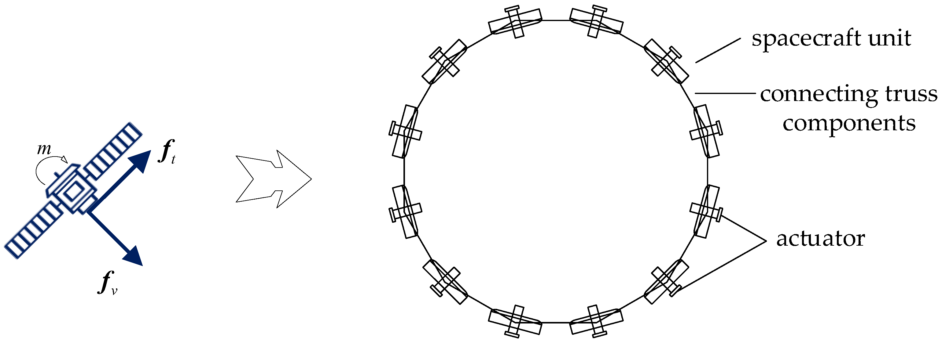
The large circular spatial structure, illustrated in
Figure 1, consists of
spacecraft unit structures forming a closed or semi-closed ring. (The method presented here is scalable and not limited to the 12-unit configuration shown in
Figure 1;
can represent a much larger number of units.) Each unit structure is equipped with independent functional modules, such as propulsion systems, power supplies, and communication systems, ensuring the proper operation of the entire structure. The unit structures are connected by articulated joints using connecting truss structures, allowing for free rotation within a certain range to adapt to different spatial environments and mission requirements. These connecting trusses also possess a certain degree of rigidity and strength to ensure the stability and safety of the entire structure. The diameter of the circular structure can vary from tens of meters to hundreds of meters, depending on specific mission requirements. This type of structure is applicable to large-scale circular space antennas, tether satellite constellations, and other applications. The actuator force, moment, and external disturbances are applied to the centroid of the spacecraft unit structure, with their directions decomposable into horizontal and vertical components within the plane. Based on these assumptions, the dynamic model of the large circular spatial structure is analyzed.
Each rigid body in the system is represented by a local coordinate system fixed to it, thus effectively conveying its motion state and relative position. The position and orientation of each rigid body in the system are defined using generalized coordinates with respect to a global reference frame, encompassing the Cartesian coordinates (position) of its base point coordinate system and its direction coordinates (attitude).
For a circular structure composed of rigid links, generalized coordinates are chosen to describe the configuration of the system. Here, the position of the center of mass and the Euler angles of each rigid link are used for representation.
The generalized coordinate vector of the system can be represented as follows:
The kinetic energy
of the system is expressed as follows:
where
is the mass of the
-th rigid body,
is the position of the centroid,
is the angular velocity, and
is the moment of inertia. Since the system is in a zero-gravity state, the potential energy
.
For the individual rigid body, the generalized force
includes contributions from external forces
and external torques
:
Substituting the above expressions into the Lagrangian equations and simplifying, we obtain the equations of motion in the following form:
where
- (1)
is the mass matrix;
- (2)
is the Coriolis and centrifugal force matrix;
- (3)
is the generalized force vector.
Since the large spacecraft structure is formed into a circular structure through articulated connections, constraint equations need to be added here. Ball joint constraints allow the connection of two rigid bodies to rotate about a common point in any direction while prohibiting any translational motion along any direction. Mathematically, this constraint can be expressed as the fixed relative position of the two rigid bodies at the connection point. The positions of the connection point in the local coordinate systems of the two rigid bodies are denoted as
and
, respectively, and the ball joint constraint can be expressed as follows:
where
and
are the position vectors of the centroid of the two rigid bodies, and
and
are their rotation matrices relative to the global coordinate system. Finally, the dynamic equations of the system are solved using the Lagrange equations, which are expressed as follows:
where
represents the generalized coordinate set,
is the generalized force vector of external forces,
is the Jacobian matrix of constraint equations, and
is the Lagrange multiplier.
Considering the constraints, the equations of motion can be obtained in the following form:
Combining and solving the above equations, explicit expressions for the acceleration
and Lagrange multipliers
can be obtained:
3. Method
For the large spacecraft dynamics model built in
Section 2, this section introduces the framework of OTSS-MASS and describes the actuator allocation process for the corresponding large spacecraft control. The task allocation algorithm optimizes the assignment of control tasks
to large spacecraft substructures
, minimizing control effort while ensuring all tasks are completed. Each task and actuator have associated requirements and limitations (including direction and task value). Task dependencies are considered, prioritizing higher-value tasks. The optimal assignment matrix minimizes the overall control effort subject to all constraints. Detailed explanations of the specific implementation methods involved in each step are also provided.
3.1. Framework
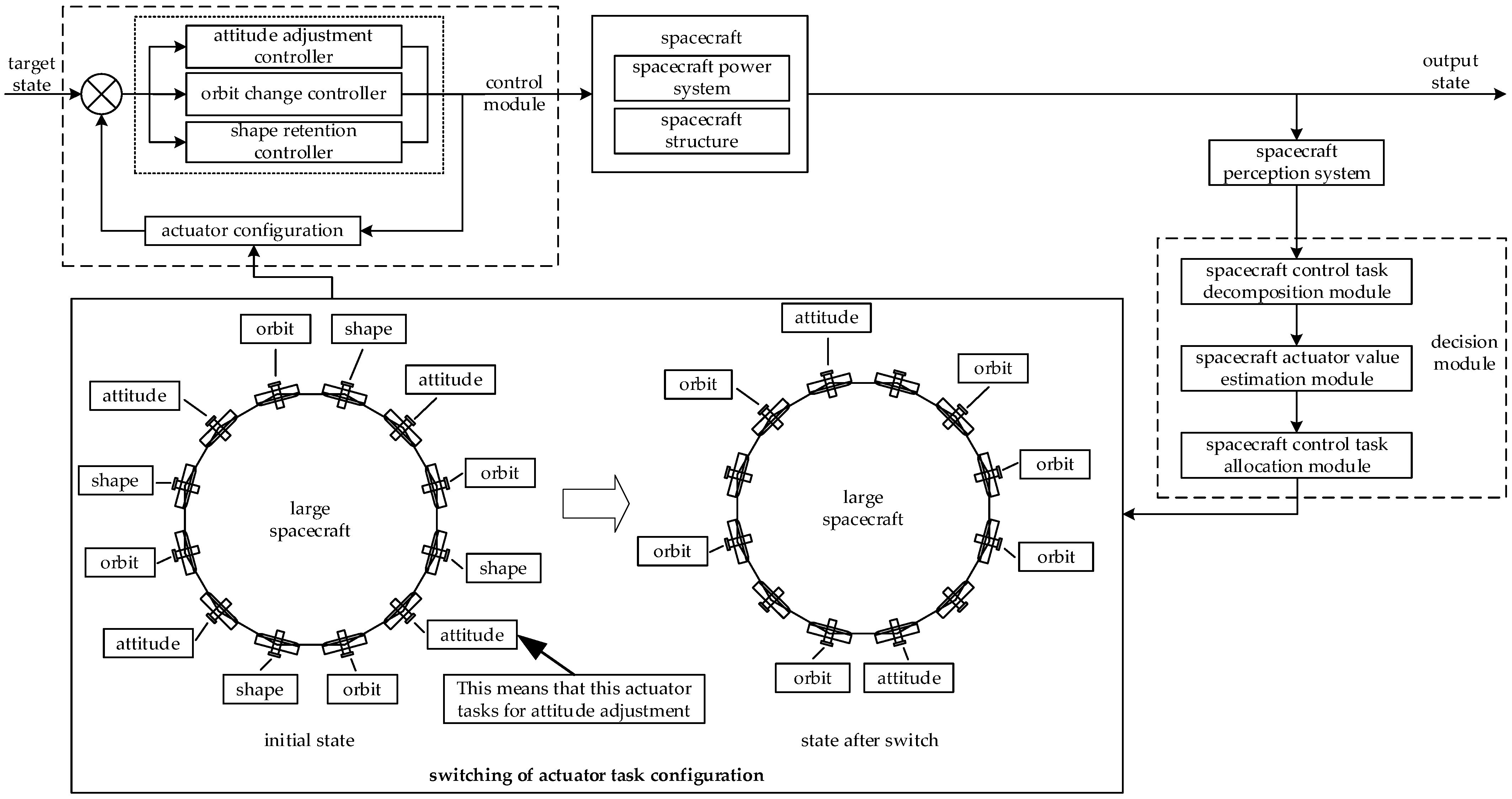
The execution process of actuator task allocation is based on the problem model constructed in
Section 2, as shown in
Figure 2. With the target state as input, the actuator works by adjusting the attitude, changing the orbit, and maintaining the shape through three controllers in the control module. It acts on the structure and power system of the large spacecraft to execute spacecraft control. The perception system obtains the state variables of the large spacecraft. The decision module decomposes the control target into tasks, evaluates the value of the actuator, and allocates the actuator tasks, achieving the switching of the actuator task allocation plan. The actuator allocation plan with switching is fed back to the actuator controller to produce the actuator signal.
With OTSS-MASS, the decision-making process of the control process from mission objective acquisition by the large spacecraft perception system to mission completion is shown in
Figure 3. First, the task decomposition scheme is derived by the task decomposition algorithm. Then, the value matrix is calculated using the task value estimation algorithm of the actuator. According to the task value matrix of the actuator, its task assignment scheme is obtained using the task assignment algorithm. Finally, the actuator executes the corresponding task according to the task assignment scheme, thus achieving the target control task.
3.2. Task Decomposition
Large spacecraft manipulation tasks typically involve multiple independent tasks such as attitude adjustment, orbit change, and shape maintenance, which often interact with each other. Rational decomposition and planning are essential to ensure a smooth operation of the entire manipulation process.
For the task decomposition algorithm of large spacecraft manipulation task , the current state variables and target state variables are taken as input, which include the large spacecraft attitude, position coordinates, operating speed, shape parameters, etc. In addition to task-type decomposition, the decomposition algorithm should also consider task decomposition from a time dimension. On the one hand, time constraints are considered, while, on the other hand, the overall task is decomposed into multiple stage subtasks, which is more conducive to the stability and reliability of the overall manipulation process.
For the attitude adjustment task , Euler angles are used here to describe the large spacecraft attitude change task, which is more intuitive and can clearly express the rotation angle of the large spacecraft, facilitating the subsequent design and understanding of the attitude adjustment control algorithm. The deviation between the three Euler attitude angles of the current state and the desired attitude Euler angles is used to measure the difference between the current attitude and the desired attitude of the large spacecraft during attitude maneuvering, which is the attitude adjustment task amount. Correspondingly, position coordinates are used to describe the orbit change task , and the difference between the initial state and the target state represents the orbit change task amount. Compared with methods such as orbital element representation, position coordinates can more intuitively reflect the position of the large spacecraft in space, facilitating the design and evaluation of orbit change control strategies. For the shape maintenance task , the shape difference between the initial state and the target state is used to describe the task amount. The shape difference can effectively reflect the relative position changes between different units, facilitating the subsequent design of shape control strategies. The task parameters involved above will be detailed in the subsequent controller design section.
By decomposing the state input parameters, the overall manipulation task is broken down into multiple independent tasks. Furthermore, in the actual large spacecraft manipulation process, the overall task can be decomposed in a chronological order, resulting in stage-wise tasks and corresponding stage-wise objectives. This process requires considering the impact of cross-stage task dependencies and task priorities. In the actuator valuation algorithm, task execution priorities can be adjusted by adjusting weights, which needs to be designed based on actual needs.
3.3. Task Value Evaluation
The value of each actuator performing any of the three tasks above is evaluated through the task evaluation algorithm of large spacecraft actuators, and the value matrix of the system
can be derived as follows:
where each element represents the value of a single actuator executing a single task. Since executing a single task impacts other tasks, the overall value is set as the sum of direct and indirect values. The system evaluates the value of any shape retention, orbit change, and attitude adjustment task for each actuator based on the large spacecraft state and the type of task using the task evaluation algorithm. Since the execution of a task by an actuator may affect the value of other tasks, indicating coupling between tasks, a joint reward function method is employed to calculate the comprehensive value of actuator task execution. The actuator task value matrix is derived as follows:
where
represents the comprehensive value of attitude adjustment task for actuator
,
represents the comprehensive value of orbit change task for actuator
, and
represents the comprehensive value of shape retention task for actuator
.
Taking the attitude adjustment value function
as an example,
is the direct value of actuator
during attitude adjustment;
represents the indirect value of orbit change during the attitude adjustment of actuator
;
represents the indirect value of shape retention during the attitude adjustment of actuator
. The calculation method for the orbit change value function
and the shape retention value function
is similar to the above.
,
, and
can be calculated as follows:
where
represents the torque vector generated by the actuator;
is the mass of the
-th unit;
is the inertia matrix of the unit rigid body;
is the angular velocity change during the attitude adjustment task process;
is the spacecraft unit velocity change for the orbit change task;
is the shape change for the shape maintenance task;
and
represent the total mass and moment of inertia of the entire large spacecraft;
,
,
are the weight proportion coefficients;
is the distance from the
-th unit to the center of rotation;
represents the kinetic energy of attitude adjustment;
represents the velocity change per unit mass, and matrix multiplication is used to calculate the kinetic energy of attitude adjustment and the squared sum of velocity changes;
represents the sum of all unit centripetal acceleration changes. The
function and
function are introduced here to represent the influence factors of orbit change task amount and shape maintenance task amount.
3.4. Task Allocation
With OTSS-MASS and the value matrix, different planning algorithms can be selected according to the actual situation to perform large spacecraft task assignments. The greedy algorithm is used as an example to present the execution process of task assignment for the actuator with OTSS-MASS, as shown in
Figure 4.
Task priority is determined by preset rules reflecting task importance. For example, orbital transfer tasks are prioritized when deformation is small, while shape maintenance tasks take priority above a deformation threshold. Attitude control is assigned last. Alternatively, task selection uses the value matrix. This highlights the method’s flexibility. The specific process is as follows. The maximum value of the column vector in the value matrix containing the specified task is extracted. The actuator is assigned the specified task, and the row of the actuator is zeroed. Repeat the above steps until the task is completed, where the column is cleared to zero, and proceed to the next task. If there is an upper limit constraint on the number of actuators for a specified task and the upper limit is exceeded, the actuators are assigned to other tasks until all tasks meet the requirements.
Whether a task can be accomplished under OTSS-MASS depends on the allocation strategy design, which should be tailored to suit specific circumstances and task types. Taking the case of shaping a particular form as an example, more actuators for a multi-rigid-body large spacecraft are evidently advantageous for task completion, but an excessive number of actuators involved in the shaping process may impede other tasks. Therefore, designing a strategy to constrain the number of actuators could help. Furthermore, the weighting coefficient of the value function can be adjusted when designing the large spacecraft task allocation strategy by controlling the proportion of different tasks’ values and ensuring task completion priority based on actual conditions.
4. Controller Design
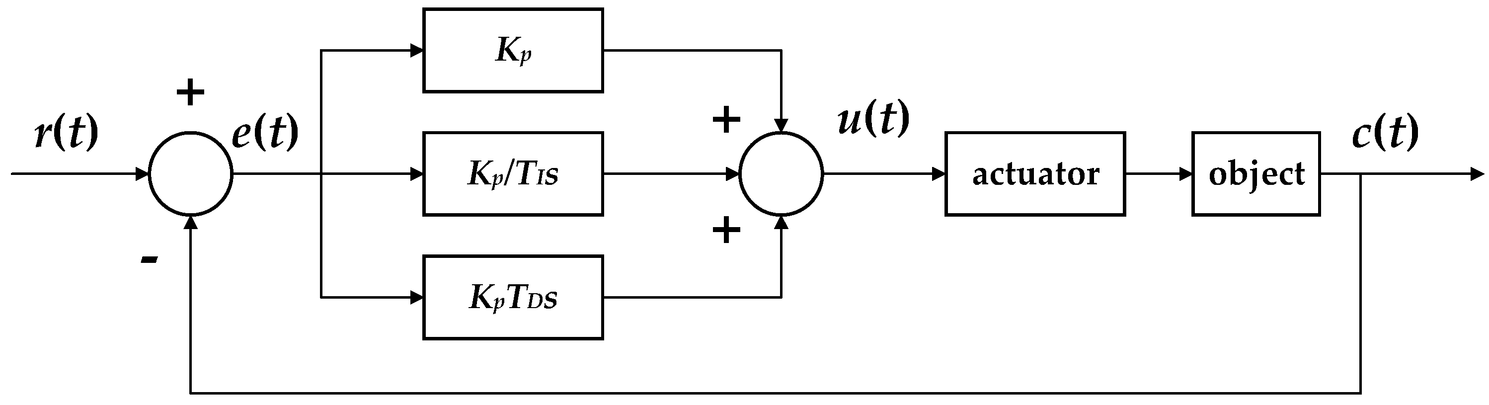
In order to verify the actual effect of OTSS-MASS on actuator switching configuration, classical PID controller decisions are introduced to the spacecraft’s control process in the spatial plane. The PID controller is a typical feedback control mechanism based on errors. The implementation of the PID controller in actual system control is shown in
Figure 5.
4.1. Shape Retention
The shape retention control algorithm for large spacecrafts is designed based on the deformation of the structure, mainly reflected in its in-plane vibration. Using the centroids of the spacecraft members as observation points, the virtual centroid
of the spatial structure is constructed. The objective of shape retention control is to ensure that the distance from the centroid of each member to the centroid of the overall structure equals the preset target value. The virtual centroid of the spatial structure can be calculated as follows:
The calculation method for the current state distance
between the centroid of the structure member and the centroid of the overall spacecraft is as follows:
The target distance between the centroid of the spacecraft member and the centroid of the overall spacecraft is the radius of the inscribed circle in a regular polygon spacecraft, which can be derived from the spacecraft size characteristics.
The control target of the shape retention index
for controlling variables throughout the entire process is as follows:
4.2. Orbit Change
The orbit change controller design focuses mainly on the coplanar orbit change task on the geostationary orbit (GEO). Orbital maneuver refers to a spacecraft altering its orbital elements using its propulsion and control systems.
In practical applications, when controlling a spacecraft to achieve in-plane position movement for orbit change, the orbit change indicator can be represented by various methods, including orbital element representation, velocity vector representation, position coordinate representation, etc. When using the position coordinate representation, we typically use the three-dimensional coordinates and velocity vector in the Cartesian coordinate system (rectangular coordinate system) to represent the spacecraft’s position at a given time. For in-plane position movement, assuming the spacecraft moves within the same plane, the z-coordinate remains unchanged.
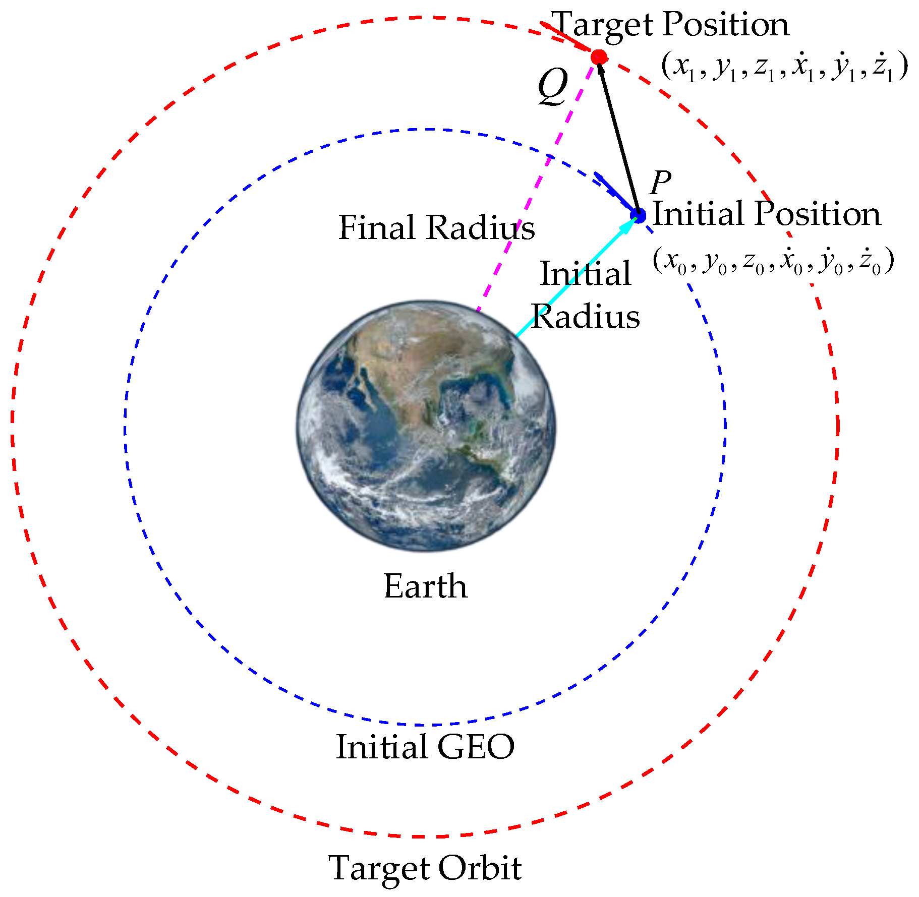
As shown in
Figure 6, suppose the coordinates of point
on the initial orbit are
, then these coordinates are related to the orbital elements such as the semi-major axis, eccentricity, and true anomaly of the orbit. Let the coordinates of the corresponding point
on the target orbit be
. Since this is an in-plane shift,
.
The orbit change index
is calculated as follows:
Through the above derivation, we can obtain the orbital change index , which reflects the parameter differences between the target orbit and the current orbit. Taking the orbital change index as the input for the orbital change, we design an appropriate control strategy, calculate the required control amount, and apply it to the spacecraft, thereby completing the orbital change task.
4.3. Attitude Adjustment
The attitude kinematics equation is used to describe the attitude angle changes of large spacecrafts. Commonly used pose description methods include Euler angle, quaternion, and Rodriguez parameter, among which the geometric meaning of Euler angle description is intuitive and clear.
The deviation
between the Euler angles of the output state and the expected Euler angle is used to measure the difference between the current spacecraft attitude and the expected attitude during attitude maneuvering. It is important to note that for the non-rigid ring structure, its attitude is defined by the orientation of a local coordinate frame attached to its center of mass, rather than the orientation of its center of mass itself.
In the equation, the three Euler attitude angles of the current output state are pitch angle
, yaw angle
, and rolling angle
, and the expected Euler attitude angle position of the target attitude is
. Then,
where
is the expected pitch angle,
is the expected yaw angle, and
is the expected rolling angle.
5. Simulations
Based on the above controller and scheme designs, the system control scheme is established. With the system dynamics equation in Lagrange form derived above, the simulation model of the large spacecraft large spacecraft control process is established. In the system dynamics model, is the generalized coordinate set, and is the generalized force vector of the external force.
In the simulation model, the centroid of the rigid body of the spacecraft member is selected as the position sampling point, the deviation from the target state serves as the input of the PID controller, and the operating force of each actuator serves as the external exciting force
of the large spatial structure to realize its control. The control block diagram of the system is shown in
Figure 7. The input to the simulation model is the driving force at each centroid position. Following task decomposition with the proposed algorithms, the allocation strategy of force on each centroid allows the task estimation algorithm to evaluate the tasks executed by each actuator. Finally, the task execution switch in the task allocation module of the actuator is implemented, and the spacecraft control task is achieved through the controller.
A hinged octagonal spacecraft model is established to simulate the control process of large spacecrafts, according to the parameter listed in
Table 1. To simplify the simulations and highlight OTSS-MASS’s task allocation and scheduling performance, only Earth’s gravity was considered in a simplified force model. Other forces (solar radiation pressure and lunar gravity) are negligible at geostationary altitudes. This simplification clarifies the efficiency comparison between OTSS-MASS and traditional methods, better verifying OTSS-MASS’s effectiveness. Earth’s gravity is calculated using the following equation:
where
,
,
(spacecraft mass) is from
Table 1, and
is the distance to Earth’s center, the value of
on a GEO orbit is approximately 42,164 km.
During the control process, the shape stability of the large spacecraft is maintained, and the thruster group moves straight to the target position. The shape stability of the spacecraft in maneuver is a fundamental requirement, especially for large satellites. The accumulated difference between the distance of each spacecraft member from the centroid and the radius of the regular octagon is defined as the deformation characteristic, marking the degree of deformation during spacecraft maneuver. To simulate orbit change tasks, the initial centroid position coordinate is set as . Any point different from the position of point can be selected as the target position during simulation. In terms of spacecraft attitude adjustment, the target attitude angle for the mission objective is set, and the control effect is verified through simulation.
To verify the effectiveness of OTSS-MASS on large-scale spacecraft, the simulation experiment sets up a task execution process under a conventional scheme (baseline) for comparison. In this scenario, the conventional fixed approach without switching conditions is designated as , where different tasks are executed in a queue. Meanwhile, OTSS-MASS is denoted as .
Figure 8 below illustrates the trajectory and attitude angle variations of large space ring structure simulation model, set with target point
and target attitude angle
. Compared to the
,
yields a smoother trajectory and more stable attitude angle adjustments. Conversely, the
scheme shows larger trajectory deviations and greater fluctuations in attitude angle adjustments.
The variation of the spacecraft’s driving force output during simulation is shown in
Figure 9. The actuator responsible for orbit change under OTSS-MASS has achieved task switching. For the actuator responsible for task switching, this process is driven by its value changes in the orbit change and shape retention tasks. When the weighted values of the orbit change and the shape retention tasks change, the actuator task-type switches. This change in the actuator’s task type will cause a stepwise variation in the driving force. The variations in the driving force that we observe in the figure actually indicate that the actuator has undergone a task switch. As shown in
Figure 10, this illustrates the task allocation for each unit during the spacecraft maneuvering process. Under
, some units experience task switching during operation, whereas no such task switching occurs under
.
6. Simulation Results Analysis
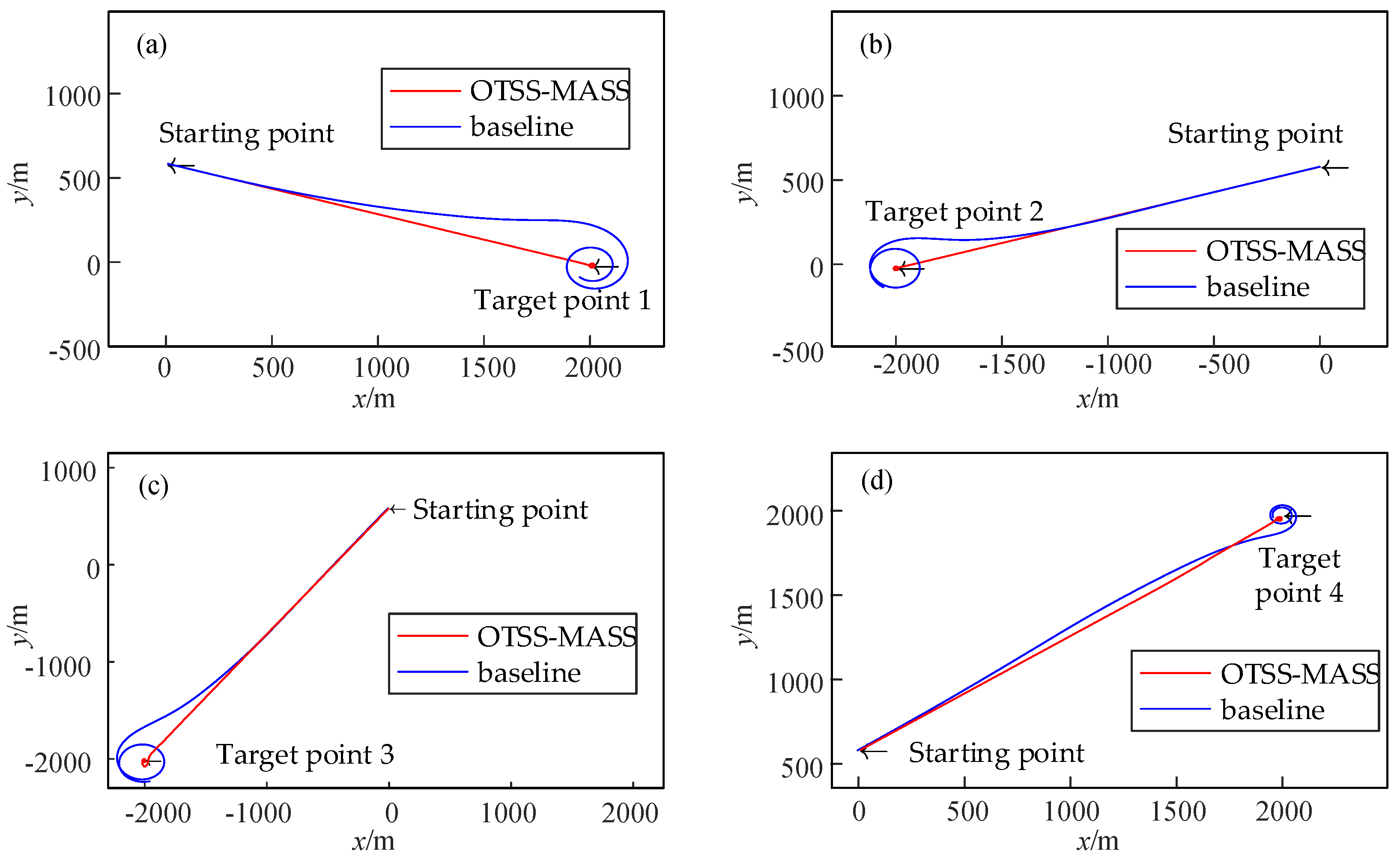
To verify the effectiveness of OTSS-MASS and consider the complex working conditions in real-world environments, different target points are designated for simulation analysis. This involves comparing indexes such as the centroid of trajectory, deformation amount, and execution speed of the multi-body spacecraft, followed by a comprehensive control effect evaluation. Furthermore, impact loads are also applied to the spacecraft in operation to validate the robustness of OTSS-MASS under impact loads.
Figure 11 illustrates the trajectory of the spacecraft’s centroid from the starting point to the target point. With OTSS-MASS, the spacecraft’s centroid can travel directly from the starting point to the target point, with only slight fluctuations at the target position. In contrast, the trajectory deviation of the multi-body spacecraft in the fixed non-switching mode (baseline) gradually increases from the starting point and significantly exceeds that under the switching scheme. The experiment simulated different target points in four directions, and the results indicate a consistent pattern across various target points.
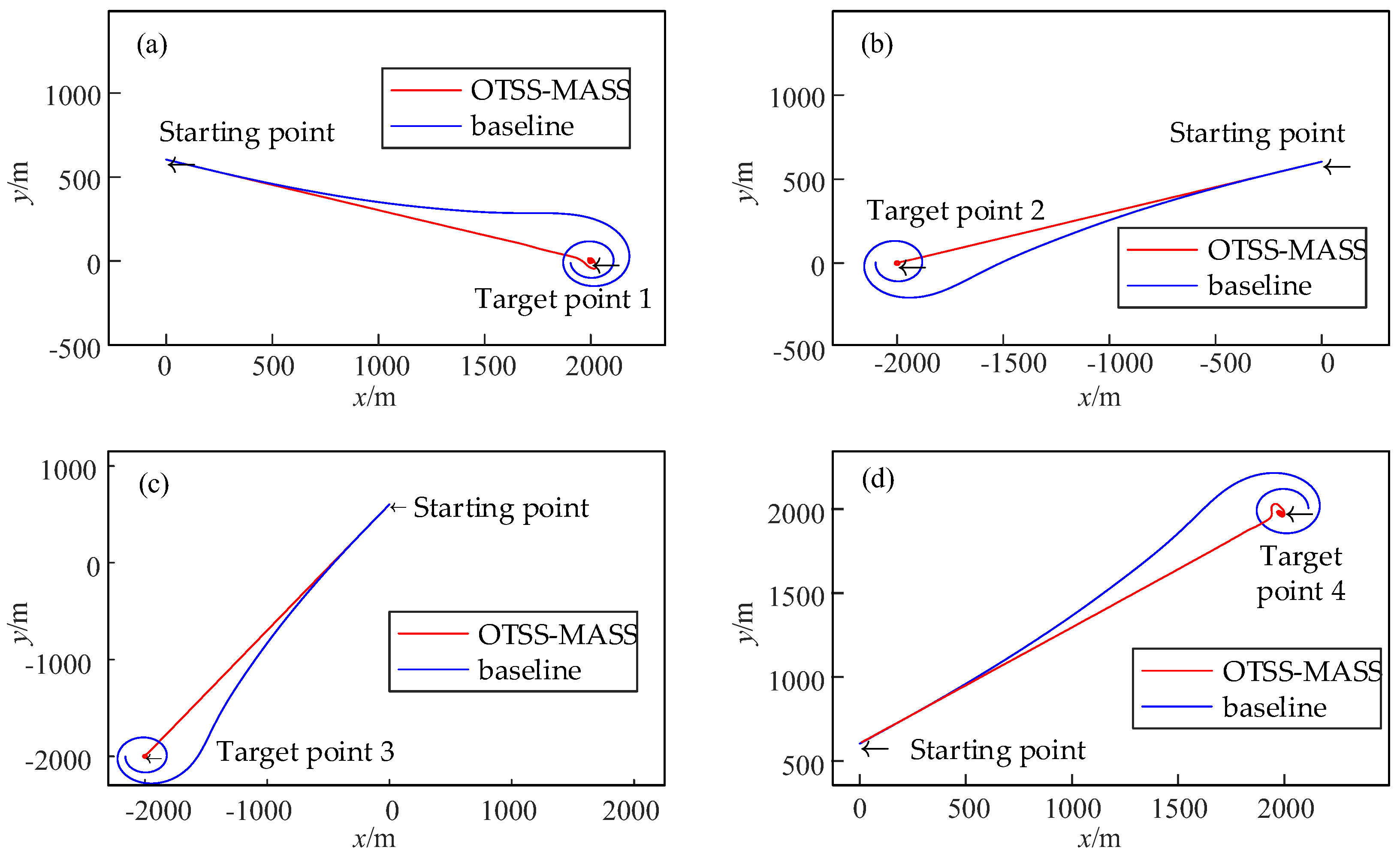
During spacecraft operation, an impact load is applied to the centroid of a single spacecraft member for 1 s to simulate a space debris impact, thereby verifying the robustness of OTSS-MASS under impact loads. The simulation results demonstrate that OTSS-MASS still exhibits good stability under impact loads, while the fixed non-switching mode results in an increased trajectory deviation, as shown in
Figure 12. This simulation set verifies that switching modes can maintain relatively good spacecraft robustness under impact loads.
Figure 13a shows that the impact load significantly affects the centroid trajectory of the spacecraft, with a noticeable increase in deviation. However, the influence on the centroid trajectory in switching mode under the same impact load is minimal, as shown in
Figure 13b. The simulation verifies that OTSS-MASS exhibits good anti-interference capability for multi-body spacecraft under impact loads.
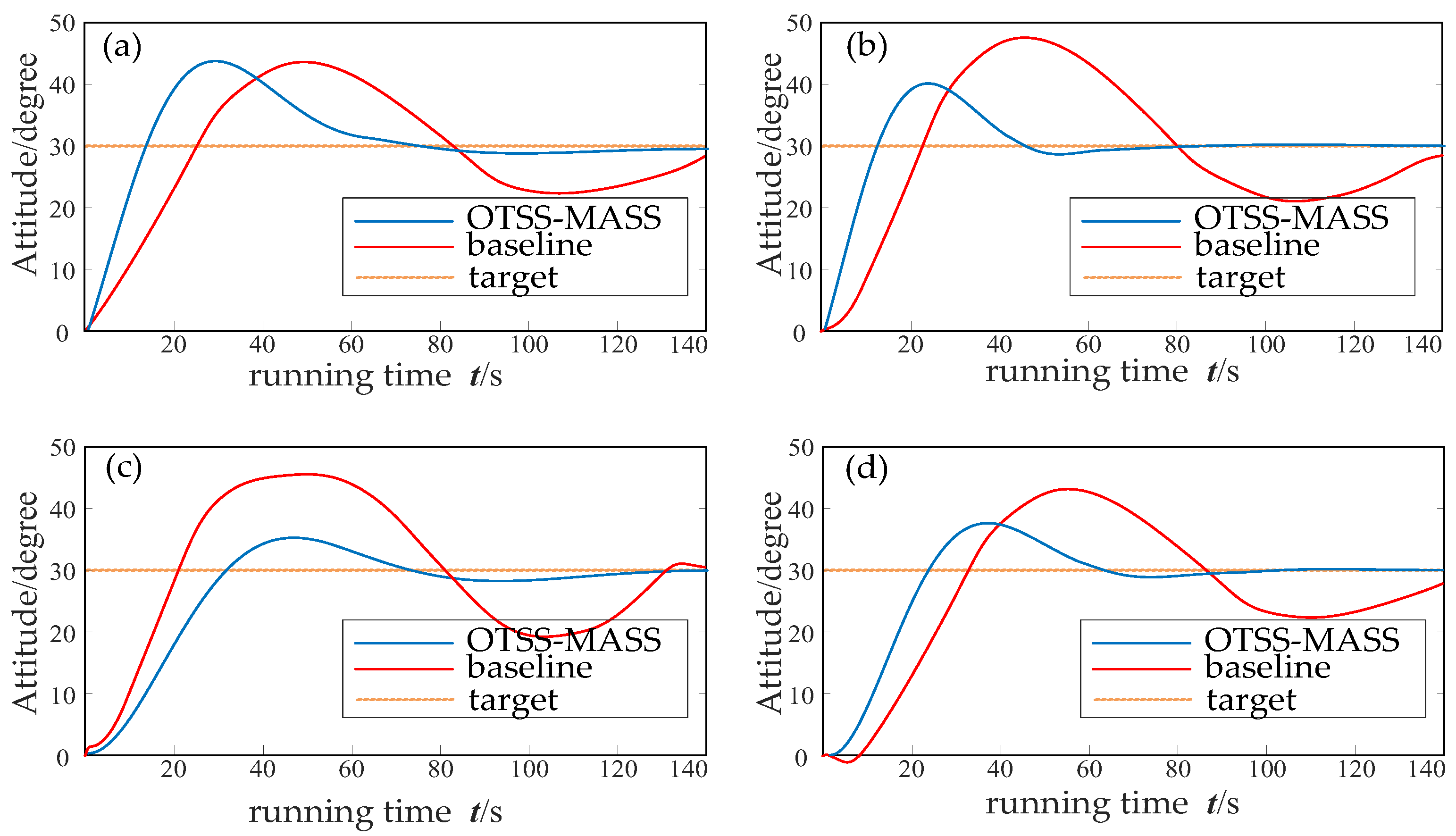
Figure 14 highlights the advantage of the OTSS-MASS method in attitude control during the manipulation process of the multi-body spacecraft. Using the horizontal attitude angle as the observation variable, the baseline method, which employs a fixed task sequence, demonstrates a significantly longer time to achieve the target attitude angle (30°) compared to the OTSS-MASS method. Moreover, the baseline approach exhibits greater overshoot in the attitude angle.
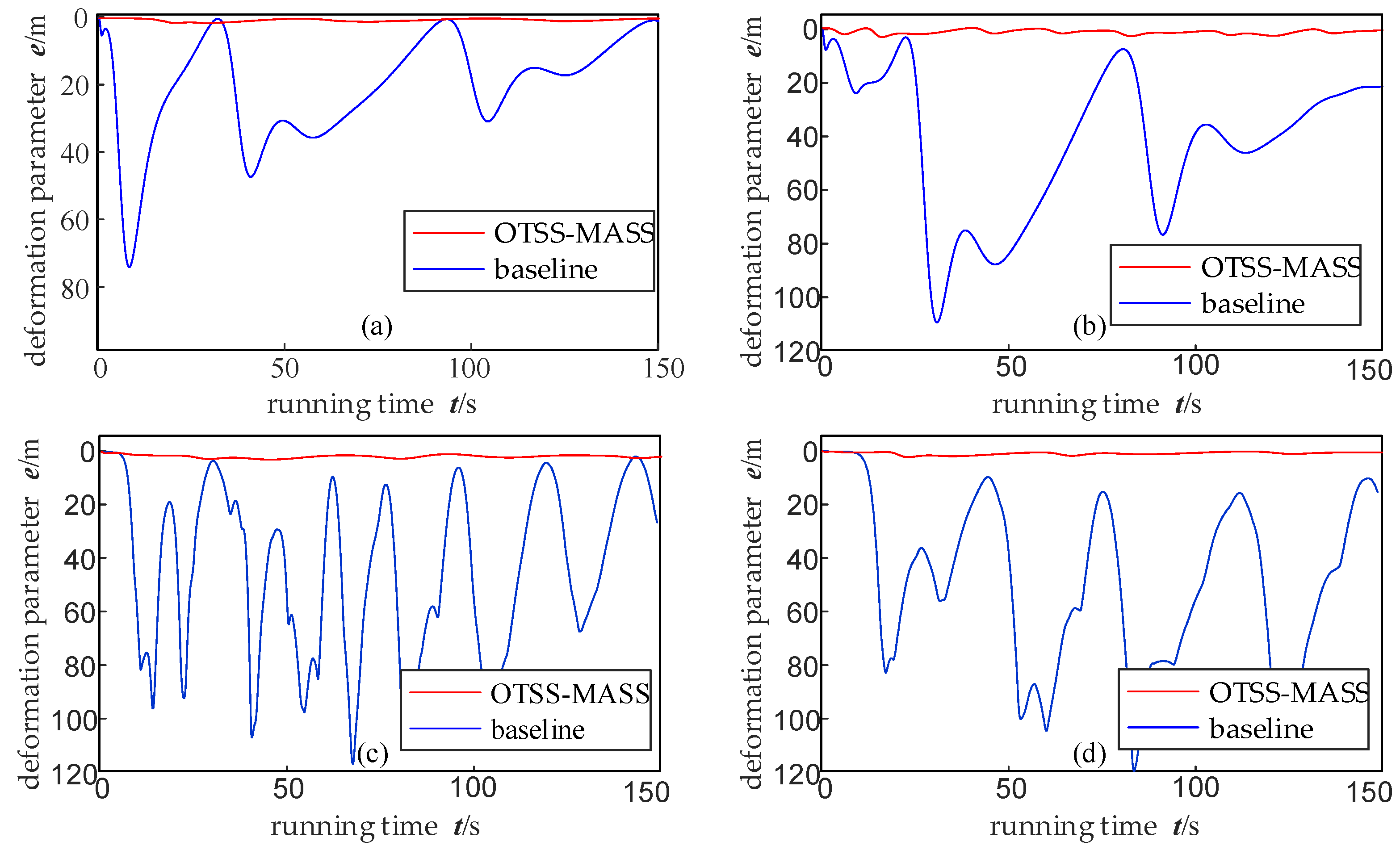
In order to confirm the effectiveness of OTSS-MASS in maintaining the shape of multi-body spacecraft during control processes, a deformation parameter is introduced as a shape preservation indicator. The calculation of parameter involves defining a virtual centroid as the average position of each member’s centroid, calculating the distance between each member’s centroid and the virtual centroid, subtracting this distance from the inscribed circle radius of a standard octagon and summing these differences. Therefore, a larger parameter indicates poorer shape preservation and vice versa.
With different target points during orbital changes, OTSS-MASS results in significantly smaller overall deformation parameters than the non-switching mode. Thus, OTSS-MASS has a more pronounced effect on preserving spacecraft shape during orbital maneuvers, as shown in
Figure 15.
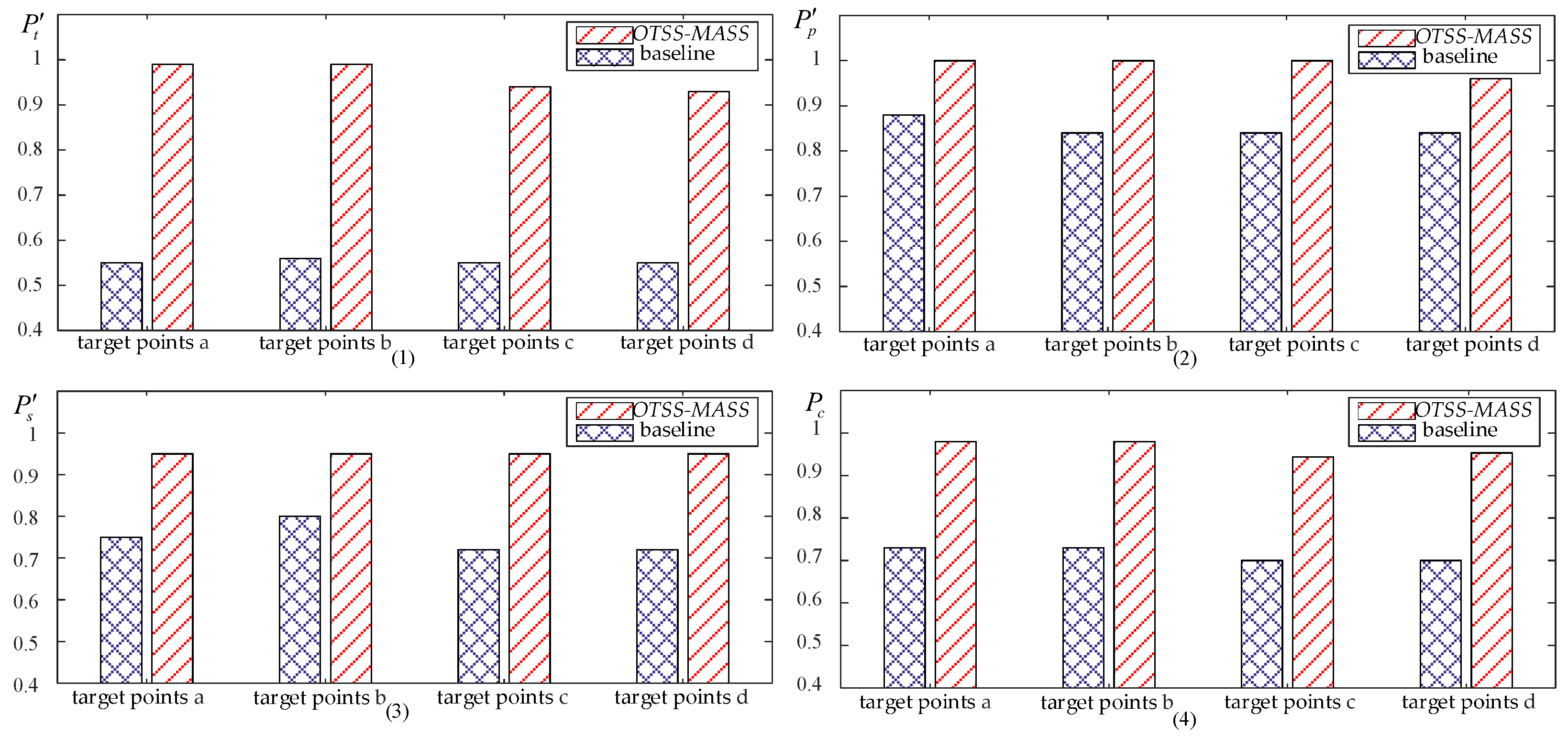
The simulation results show that OTSS-MASS has various improvements in influencing the spacecraft control process. In order to objectively evaluate the overall impact, three key indexes, i.e., time index , trajectory index , and shape index , are selected to evaluate the spacecraft control process. The time index represents the time for the centroid of the multi-body spacecraft to reach the target point. The trajectory index is obtained by integrating the absolute deviation between the centroid during operation and an ideal trajectory within time index . It represents a comprehensive measure of deviation in the multi-body spacecraft trajectories during control processes. Meanwhile, shape index is obtained by integrating the absolute value of deformation parameter over time period during spatial maneuvering of the multi-body spacecraft. describes the overall deformation throughout this process.
Due to OTSS-MASS’s capability to allocate and prioritize actuators based on the importance of each task, a comprehensive control effectiveness evaluation is conducted by introducing normalization and weighting coefficients to time index , trajectory index , and shape index to assess the overall control process.
The specific normalization process is as follows:
(1) For the time index
, if the optimal time index
in all experiments is set as the reference value 1, then the normalized time index
can be calculated as follows:
(2) To ensure a rapid decay of the normalized trajectory index
and shape index
in regions with low index values, an improved sigmoid function
is employed. This function normalizes both trajectory index
and shape index
to a range between 0 and 1, making the function more sensitive to situations where one indicator exhibits a low value, potentially signaling the infeasibility of a task.
When calculating the comprehensive index
, weight coefficients
,
, and
are introduced as the weighting factors for time index
, trajectory index
, and shape index
. In this paper, they are all set to 1 in the calculations as an example. In practical applications, these values can be adjusted or optimized based on specific requirements to emphasize different indexes.
The experimental data of key indexes for the multi-body spacecraft control process, including time index
, trajectory index
, and shape index
, are processed with the above calculation method, as shown in
Table 2. As shown in
Figure 16 and
Figure 17, these data are used to plot bar charts comparing these indexes under different target points with or without OTSS-MASS. Ultimately, bar charts comparing time index
, trajectory index
, shape index
, and comprehensive index
for different states and target points in the multi-body spacecraft control process are obtained.
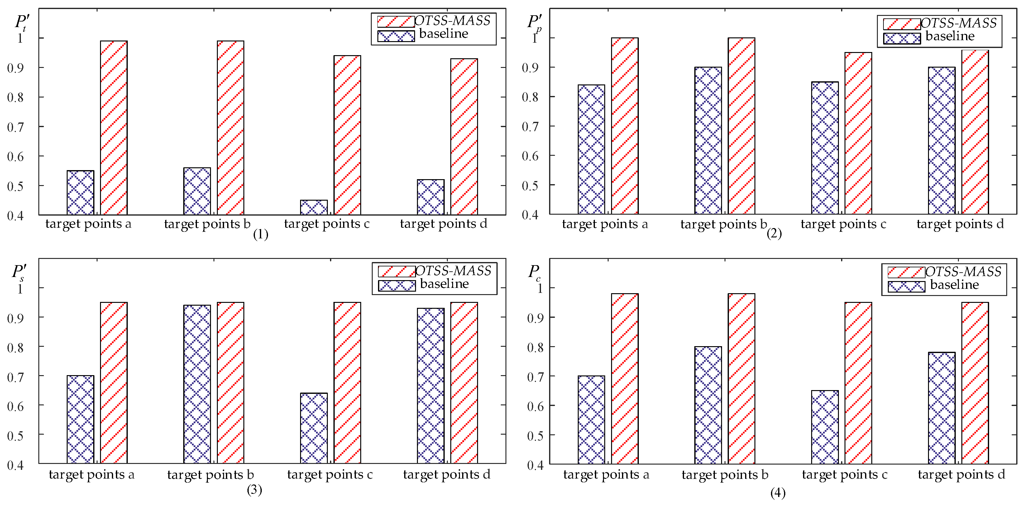
The calculations indicate that OTSS-MASS exhibits an improved effect on all indexes. Under conventional non-impact load conditions, the improvement of comprehensive index reaches 25%, while the impact on time index is more obvious, with an increase of over 40%. The average increase in trajectory index is 12%, and the average increase in shape index is 21%.
Under the impact load, the time index
of OTSS-MASS increases by 46% on average, the trajectory index
increases by 10% on average, the shape index
increases by 17% on average, and the comprehensive index
increases by about 24%. Under the impact load, the increase in each index of the multi-body spacecraft control has more obvious fluctuations, and the standard deviation of its increase ratio also increases significantly, as shown in
Table 3.


