Article

Dynamics Model and Its Verification of Aerospace Three-Ring Gear Reducer

1
School of Automation, Northwestern Polytechnical University, Xi’an 710072, China
2
Lanzhou Wanli Aviation Electromechanical Co., Ltd., Lanzhou 100084, China
3
Key Laboratory of Aeroelectric Actuation of Gansu Province, Lanzhou 730070, China
4
School of Mechanical and Electrical Engineering, Lanzhou University of Technology, Lanzhou 730050, China
*
Author to whom correspondence should be addressed.
Aerospace 2024, 11(12), 1049; https://doi.org/10.3390/aerospace11121049
Submission received: 31 October 2024 / Revised: 16 December 2024 / Accepted: 18 December 2024 / Published: 21 December 2024
(This article belongs to the Section Aeronautics)

Abstract

:
This paper proposes a nonlinear dynamic modeling method based on the lumped mass approach to address the challenge of modeling the vibrations of the output external gear and internal gear plate in an aerospace three-ring gear reducer. A vibration model of bending–torsion coupling with 12 degrees of freedom was established by comprehensively considering factors such as the time-varying meshing stiffness, gear transmission error, tooth side clearance, bearing support stiffness, and damping. Finite element modal analysis and vibration test results verified the vibration model’s accuracy and applicability, indicating that the model is both precise and valid. The vibration model was solved using the fourth-order, five-level Runge–Kutta method. The results show that the symmetrical arrangement design of the internal gear plate cancels the vibrations in all directions and suppresses the vibration displacement response on the output shaft.

1. Introduction

The aerospace three-ring reducer is the core component of the aerospace electromechanical actuator, and its accuracy, power-to-weight ratio, transmission efficiency, and reliability are directly related to the overall system performance, especially the response of the transmission system under external excitation during operation. The dynamic characteristics under complex external and internal coupling excitation in the aviation environment have a crucial impact on the realization of the aerospace electromechanical actuator’s function.
The three-ring reducer is a typical small tooth difference transmission, which is a new type of transmission device developed in recent years. It has the advantages of a precise large transmission ratio, compact structure, and strong load capacity, and can largely meet the requirements of modern aviation equipment for the actuator. For the three-ring reducer, Wang Jiaxu et al. used the lumped mass method to establish its 12-degree-of-freedom nonlinear dynamic model of bending torsion coupling [1,2]. Yang Huaifeng et al. established an equivalent model [3] to study the impact of different error parameters on the effect characteristics of the reduction mechanism with the small tooth difference. Zhang Jindong et al. conducted an in-depth analysis of the dynamic excitations, such as meshing stiffness excitation and error excitation, of the NN-type small tooth difference planetary reducer, and established a vibration model [4]. Hassen F et al. [5] established a dynamic model of the multistage idler spur and helical gears by comprehensively considering the internal excitation and external forcing parts of the transmission system, and investigated the effects of the transmission error, tooth deviation, and external excitation on the dynamic loads. Wang et al. [6] established a torsional nonlinear dynamic model of the GFT (Geared Turbofan Engine) engine by comprehensively considering the internal excitation of the transmission system, and other factors, and investigating the changing law of the system motion state. Zhao et al. [7] constructed a pure torsion model considering multiple nonlinearities for a wind turbine gearbox with parallel gear sets and two planetary gear sets. Yang Jianmin et al. [8] incorporated the elastic deformation and eccentricity error of each component in the dynamic meshing force into the nonlinear dynamic model of the aerospace three-ring reducer, revealing the superharmonic resonance behavior of the aerospace three-ring reducer. Li Qi et al. [9] focused on the planetary reducer with a small tooth difference as their research subject. They comprehensively considered factors such as the time-varying meshing stiffness, gear transfer error, and tooth measurement gap, establishing a nonlinear dynamic model of the planetary reducer using the concentrated mass method. The model’s accuracy was verified by comparing the calculation results with the experimental findings.
Zhu et al. [10] established a dynamics model of a six-degree-of-freedom coupled system, and, based on the numerical solution of the elastic fluid lubrication, an improved dynamic transmission error model was established. In 2021, Hood et al. [11] used a finite element/contact mechanics model to accurately capture localized softness due to motion, tooth and rim deformation, vibration, and root cracks to determine the calculated static transmission error and tooth mesh stiffness. Kumar et al. [12] applied Lagrange’s equation to model the dynamics of a wind turbine drive train by considering the effect of cracks on the time-varying meshing stiffness of the gear pair during meshing. Wang et al. [6] considered the internal excitation of the transmission system, and other factors, to establish the GFT engine’s torsional nonlinear dynamics model, and studied the change law of the system motion state. Zhai et al. [13] constructed a bend–twist–axis–pendulum fully coupled vibration model of a wind turbine gearbox by considering factors such as the assembly error generated by the planetary carrier in the planetary wheel system, the axial assembly error, and the spatial assembly error; by solving this model, it was verified that the reconstructed model could eliminate the numerical errors caused by the direct matching of the tooth contact model and the gear substrate in the general model. Sanjib C et al. [14] constructed a nonlinear dynamic model of gears in the case of a high rotational speed by equating the gears as a rigid disk and analyzing the kinematic state.
Zhang used ANSYS Workbench software to conduct modal analysis on the three-dimensional virtual prototype of the NN-type small tooth difference involute planetary gear reducer and completed the optimized design of the reducer [15]. Huang Chao et al. used the dynamic contact finite element method to obtain the internal dynamic excitation of the gear teeth meshing, calculated the intrinsic frequency of the planetary gear mechanism according to the established dynamic finite element modal, and studied its structural dynamic response and acceleration noise [16] by applying the Lanczos method to obtain the intrinsic frequency and the corresponding vibration modes of the gear reducer. The modal data were analyzed using the PolyMAX modal identification method to obtain the modal frequencies and damping ratios, and the experimental modal parameters were verified according to the Modal Assurance Criterion (MAC) [17]. Hu et al. [18] analyzed the effect of dislocation coefficients and helix angles on the transient meshing performance in a finite element model of a gear pair based on the explicit dynamic module embedded in commercial finite element analysis software. Wang et al. [19] used the ANSYS/LS-DYNA analysis module to establish a dynamic contact and tooth impact model considering tooth friction, tooth side clearance, and other factors to simulate the vibration response of the transmission system under real working conditions. Tristan M E et al. [20] used a finite element model to obtain the intrinsic frequency and vibration pattern of the gear pair, and compared the calculated results with the theoretical model of the dynamics constructed by the concentrated parameter method as well as the experiments for verification.
Huang et al. used Pro/E software to establish a parameterized solid model of the gear ring plate and conducted modal analysis using ANSYS software [21]. Liu et al. established a finite element model of a three-ring reducer considering tooth deformation based on relevant dynamic theories, analyzed the finite element models under different phase angles, obtained the actual number of contact teeth and the contact tooth stress [22], and studied the impact of the internal tooth difference accuracy on the vibration and noise. In order to avoid problems such as impact, a high temperature, reduced lifespan, and the inability to assemble the three-ring reducer, the positioning and adjustment angle of the internal toothed disk has been optimized [23]. Tong Yu et al. carried out a multi-body dynamics simulation analysis with the help of ANSYS and ADAMS software to calculate the contact stiffness and damping, to explore in detail the dynamic response of the three-ring gear reducer with fewer gears under different working conditions, and to carry out a frequency response characteristic analysis [24]. Du Wentao established the reaction force equation and supplementary equations for planetary bearings based on displacement deformation conditions, and obtained the reaction force curves for the planetary bearings and box bearings of the three-ring reducer [25]. He also used ADAMS software to establish a virtual prototype, and obtained the curve diagrams of the planetary bearing force and the meshing force of the gear pair in the time domain [26] through simulation experiments. Wen Fang et al. established a thermoelastic coupled finite element model of the gear shaft–bearing case system of the three-ring reducer to derive the temperature field of the whole machine of the three-ring reducer, and applied the dynamic excitation inside of the gears to carry out the numerical simulation of the dynamic response of the whole machine [27]. Zhao Zhicong used finite element analysis technology to flexibly treat the key components of the three-ring reducer internal gear ring plate, completed the derivation of the simulation parameters such as the contact stiffness and damping of the internal gear pair, and constructed a rigid–flexible coupled virtual prototype of the three-ring reducer [28]. Liu et al. [29,30,31,32] first proposed a new solution method for nonlinear dynamical models, abandoning the conventional fine integration method or the Runge–Kutta method, verifying the superiority of the proposed model, and extracting the phase diagram and time course diagram of the system from the case; as a result, it was verified that the proposed computational method has good convergence properties. Li et al. [33] established a finite element model considering factors such as the tooth side clearance, meshing error, and time-varying meshing error, and solved the model based on the display dynamics module in the software. Zhang Tao et al. [34] used the editable module of ANSYS to conduct the secondary development of the software by using the APDL language, and studied the influence of the tooth profile error on the dynamic contact force based on Hertz contact theory.
The focus of the above research is on the working principle, parameters, and structure of the three-ring reducer and transmission mechanism. The analysis of the dynamic characteristics of the three-ring reducer is mainly based on a virtual prototype and simulation analysis without forming a complete dynamic analysis system of the three-ring reducer. To sum up, this paper aims to solve the vibration problem of the three-ring reducer in the aerospace electromechanical actuator through the establishment of a nonlinear dynamic model to carry out the dynamic characteristic analysis, so to complete the study of the bending–torsion coupling nonlinear vibration, and, at the same time, using the simulation and experiment to complete the modal analysis and vibration response analysis of the aerospace three-ring reducer structure.

2. Parameter Calculation and Dynamic Model Establishment of Aerospace Three-Ring Reducer

The design of the structural parameters of the aerospace three-ring reducer directly affects its dynamic characteristics, which is evident in the vibration shape and amplitude of the aerospace electromechanical actuator during product application.

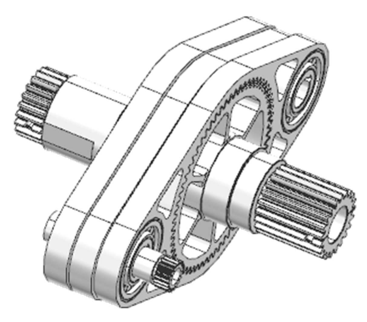
2.1. Dynamic Model of Aerospace Three-Ring Reducer

In this paper, the three-dimensional assembly model of the aerospace three-ring reducer is shown in Figure 1. The aerospace three-ring reducer three-dimensional assembly model exploded drawing is depicted in Figure 2. It features the following three parallel axes: the output shaft, input shaft, and support shaft. Each of these shafts is equipped with a deep groove ball bearing at both ends in the support shaft section. Additionally, the internal gear is linked to the input shaft and support shaft via the planetary bearings. The meshing of the internal and external gears is a typical few teeth difference meshing, completing the power output.
Based on the transmission structure characteristics of the aerospace three-ring reducer and the coupling relationship between substructures, such as the shaft system, its dynamic model can be established. For the convenience of the modeling and solving, the model is reasonably simplified, which only considers the vibration in the x- and y-axis directions, and the rotation of the gear around the axis. The x-axis direction refers to the horizontal alignment connecting the center points of the two outer circular holes on the inner tooth plate. The z-axis direction indicates the central axis orientation of the output gear, while the y-axis direction pertains to the vertical alignment of the x- and z-axes. Figure 2 shows the coupling dynamic relationship between the external gear and the internal gear plate 1, while the coupling dynamic relationship between the other two internal gear plates and the external gear differs from Figure 2 by only a 120° phase difference.
In Figure 3, km, cm, and fm are the nonlinear force displacement functions composed of the meshing stiffness, meshing damping, and backlash between the internal and external gears, respectively; kb1 and cb1 represent the support shafts.
Here, kb2 and cb2 represent the support stiffness and support damping, respectively, of the input shaft bearing; kb3 and cb3 represent the support stiffness and support damping, respectively, of the planetary bearings. The stiffness and damping parameters corresponding to the other two internal gear plates are the same.
In order to simplify the intermediate transfer process, T1 and T2 are defined as the load torque and input torque of the system, respectively; x and y are the vibration displacements of the gears in the horizontal and vertical directions; θ is the angular displacement of the torsional vibration around the central axis. The subscripts c, w, n1, n2, and n3 denote the support shaft, the external gear, and the three internal gear plates, respectively, and θ1, θ2, and θ3 denote the corresponding crankshaft rotation angle when the internal gear plate performs a planar circular motion while maintaining a phase difference of 120° from each other.
Based on the above definitions (the horizontal and vertical vibration displacements of the gear and the angular displacement of the torsional vibration around the central axis), a centralized parametric model was established for the aerospace three-ring reducer, in which components such as bearings are represented by using nonlinear stiffness elements and damping elements, and the gear tooth meshing force is represented by km, cm, and fm. Considering the high-frequency internal and external excitations caused by the load torque T1, the input torque T2, and the transmission error e, the drive system is equivalently treated as gear horizontal and vertical vibration displacements, and torsional vibration displacements, which contain a total of 12 degrees of freedom, as shown in Equation (1):
Q = x w , y w , θ w , x n 1 , y n 1 , θ n 1 , x n 2 , y n 2 , θ n 2 , x n 3 , y n 3 , θ n 3
The general rotor dynamics modeling of gear transmission systems is conducted based on fixed axis gear trains, where the motion of each gear is described in an inertial frame, and the position of the meshing line does not change throughout the entire motion process. The structural characteristics of the three-ring reducer determine that the motion of the internal gear plate is in the form of the translational motion of the connecting rod in the double-crank linkage mechanism, and the meshing point and meshing line change with the rotation of the crank in the whole motion process. The translational motion of the internal gear plate increases the difficulty of establishing the nonlinear vibration equations for the aerospace three-ring reducer.
Therefore, before modeling the nonlinear vibration equations of the aerospace three-ring reducer, the motion of its meshing points in the working process should be analyzed first. The gears of the aerospace three-ring reducer are involute straight-tooth cylindrical gears, and the friction of the gear meshing and the support bearing is not considered in the dynamic modeling process. The displacement at the meshing point M during gear meshing is shown in Figure 4.
In Figure 4, the vibration displacement of the internal gear plate n1 is ( x n 1 , y n 1 ), and the torsional displacement is θn1. The vibration displacement of the external gear is ( x w , y w ), and the torsional displacement is θω. R is the radius of the index circle. The vibration displacements Mω and M n1 at the position of the meshing point on the external gear and the internal gear plate are as follows:
M w = [ R w cos ( θ + θ w ) + x w , R w sin ( θ + θ w ) + y w ] M n 1 = [ R n 1 cos ( θ θ n 1 ) R cos θ + x n 1 , R n 1 sin ( θ θ n 1 ) + R sin θ + y n 1 ]
Therefore, the relative displacement of the internal gear plate n1 and the external gear at the mesh point position is as follows:
x m 1 = M w x 1 M n 1 x = R w cos ( θ 1 + θ w ) + x w + R n 1 cos ( θ 1 θ n 1 ) R cos θ 1 x n 1 y m 1 = M w y 1 M n 1 y = R w sin ( θ 1 + θ w ) + y w + R n 1 sin ( θ 1 θ n 1 ) R sin θ 1 y n 1
The relative displacement of the vibration at the meshing point M is ( x m , y m ) . Considering the normal component of the displacement in each direction at the meshing point, it can be considered that the normal component of the relative displacement of the vibration between the internal gear plate n1 and the external gear w at the meshing point M is as follows:
Δ x 1 = x m 1 cos θ 1 Δ y 1 = y m 1 sin θ 1 Δ m 1 = Δ x 1 + Δ y 1
The normal displacement of the meshing points of the internal gear plates n2 and n3 is calculated in the same way as in Equation (5), and then the meshing force generated between the meshing gears is shown in Equation (6), as follows:
F n i = k m i f m i ( Δ m i e i ) + c m i ( Δ ˙ m i e ˙ i )
Therefore, the engagement force is divided in the x and y directions, respectively, as follows:
F n i x = [ k m i f m i ( Δ m i e i ) + c m i ( Δ ˙ m i e ˙ i ) ] cos θ i F n i y = [ k m i f m i ( Δ m i e i ) + c m i ( Δ ˙ m i e ˙ i ) ] sin θ i
In the equation, e is the static transmission error during the gear transmission process, assuming it is a simple harmonic function, as shown in Equation (7), as follows:
e i ( t ) = e r i sin ( 2 π t / T 0 i + ϕ i )
In the formula, e r i is the amplitude of the transmission error between each gear pair, t is the time of the gear movement, T0 is the period of the gear meshing, and ϕ i is the initial phase of the gear meshing. Here, f m i is the displacement function of the tooth side clearance; assuming that the tooth clearance is 2 b h , the expression can be written as follows:
f m i ( Δ m i ) = Δ m i b h ( Δ m i > b h ) 0 ( b h Δ m i b h ) Δ m i + b h ( Δ m i < b h )
The radial clearance f b i of the bearing can also be expressed in the same form as Equation (8). Similarly, the time-varying meshing stiffness is considered as a simple harmonic function of the superimposed mean meshing stiffness k p i . The meshing frequency is ω m i , the amplitude is A m i , and the initial phase of the meshing is ϕ m i ; then, the time-varying meshing stiffness is shown in Equation (9), as follows:
k m i ( t ) = k p i + j = 1 A m i sin ( j ω m i t + ϕ m i )
In summary, based on the above equation, the dynamic equation of the gear transmission system of the aerospace three-ring reducer can be derived as follows:
m w x ¨ w + c b 1 x ˙ w + k b 1 f b 1 x + F n 1 x + F n 2 x + F n 3 x = 0 m w y ¨ w + c b 1 y ˙ w + k b 1 f b 1 y + F n 1 y + F n 2 y + F n 3 y = 0 I w θ ¨ w + F n x R w + F n y R w + F n y R w T l o a d = 0 m n 1 x ¨ n 1 F n 1 x + k a f 1 a x + k b f 1 b x + c a ( θ ˙ 1 R cos θ 1 x ˙ n 1 ) + c b ( x ˙ n 1 θ ˙ 1 R cos θ 1 ) = 0 m n 1 y ¨ n 1 F n 1 y + k a f 1 a y + k b f 1 b y + c a ( θ ˙ 1 R sin θ 1 y ˙ n 1 θ ˙ n 1 l b ) + c b 3 ( y ˙ n 1 + θ ˙ n 1 l b + θ ˙ 1 R sin θ 1 ) = 0 I n 1 θ ¨ n 1 F n 1 R n 1 + [ k a f 1 a y + c a ( θ ˙ 1 R sin θ 1 y ˙ n 1 θ ˙ n 1 l b ) ] l b + [ k b f 1 b y + c b 3 ( y ˙ n 1 + θ ˙ n 1 l b + θ ˙ 1 R sin θ 1 ) ] l b = 0 m n 2 x ¨ n 2 F n 2 x + k a f 2 a x + k b f 2 b x + c a ( θ ˙ 2 R cos θ 2 x ˙ n 2 ) + c b ( x ˙ n 2 θ ˙ 2 R cos θ 2 ) = 0 m n 2 y ¨ n 2 F n 2 y + k a f 1 a y + k b f 2 b y + c a ( θ ˙ 2 R sin θ 2 y ˙ n 2 θ ˙ n 2 l b ) + c b ( y ˙ n 2 + θ ˙ n 2 l b + θ ˙ 2 R sin θ 2 ) = 0 I n 2 θ ¨ n 2 F n 2 R n 2 + [ k a f 2 a y + c a ( θ ˙ 2 R sin θ 2 y ˙ n 2 θ ˙ n 2 l b ) ] l b + [ k b f 2 b y + c b ( y ˙ n 2 + θ ˙ n 2 l b + θ ˙ 2 R sin θ 2 ) ] l b = 0 m n 3 x ¨ n 3 F n 3 x + k a f 3 a x + k b f 3 b x + c a ( θ ˙ 3 R cos θ 3 x ˙ n 3 ) + c b ( x ˙ n 3 θ ˙ 3 R cos θ 3 ) = 0 m n 3 y ¨ n 3 F n 3 y + k a f 3 a y + k b f 3 b y + c a ( θ ˙ 3 R sin θ 3 y ˙ n 3 θ ˙ n 3 l b ) + c b ( y ˙ n 3 + θ ˙ n 3 l b + θ ˙ 3 R sin θ 3 ) = 0 I n 3 θ ¨ n 3 + F n 3 R n 3 + [ k a f 3 a y + c a ( θ ˙ 3 R sin θ 3 y ˙ n 3 θ ˙ n 3 l b ) ] l b [ k b f 3 b y + c b ( y ˙ n 3 + θ ˙ n 3 l b + θ ˙ 3 R sin θ 3 ) ] l b = 0
In the formula, mi is the concentrated mass of the gear; Ii is the rotational inertia of the gear; θi represents the rotation angle displacement. The above 12 equations are a system of a 12-degree-of-freedom variable parameter, semi-positive definite, and nonlinear second-order differential equations, which have both linear and nonlinear elastic restoring forces.

2.2. Calculation of Dynamic Parameters

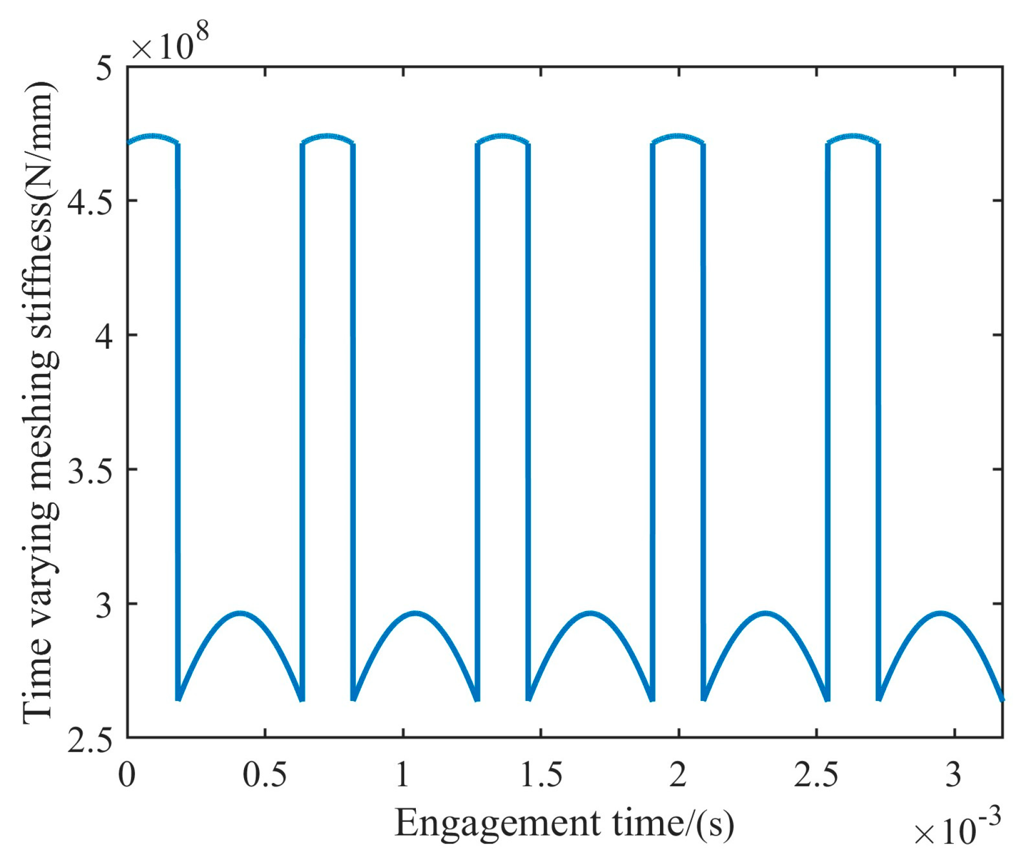
2.2.1. Meshing Stiffness

In this paper, the Ishikawa method is employed to calculate the meshing stiffness of the meshing unit. The principle of the Ishikawa method involves treating the gear as a cantilever beam formed by the combination of a trapezoid and a rectangle, and analyzing it by considering the long side of the rectangle as a critical cross-section of the gear teeth. The meshing stiffness was calculated using the 30° tangent method to obtain the deformation δ of one gear tooth at the point of load application along the direction of the meshing line, as follows:
δ = δ b r + δ b t + δ s + δ G
where δbr is the bending deflection of the rectangular part, δbt is the trapezoidal part of the deformation, δs is the shear deformation, and δG is the original part of the tilt deformation.
Hertzian contact deformation takes place during gear meshing as a result of contact, represented by the total deformations of the individual gear teeth along the line of mesh of the load action δ, as follows:
δ Σ = δ 1 + δ 2 + δ p v
where δ1 and δ2 are the deformations of the two gear teeth, and δpv is the contact deformation. The meshing stiffness is calculated as follows:
k m = F n δ Σ
where Fn is the normal meshing force.
The meshing unit was analyzed alongside the Ishikawa method to derive the meshing stiffness variation curve, as illustrated in Figure 5.

2.2.2. Meshing Damping

During the meshing process of the gears, interference or friction between them can generate resistance at the gear surfaces, a phenomenon known as meshing damping. In gear dynamics analysis, the calculation of meshing damping is primarily estimated through empirical methods to determine the meshing damping of gears. The mesh damping cm is calculated as follows:
c m = 2 ξ m k m r b 1 2 r b 2 2 I 1 I 2 I 1 r b 1 2 + I 2 r b 2 2
where rb1 and rb2 are the radii of the base circle of the gear; I1 and I2 are the moment of inertia of the gear; km is the mean value of the time-varying meshing stiffness of the gears; ξm is the damping ratio; the value range is 0.03–0.17.

3. Validation of the Correctness of the Dynamic Model

3.1. Modal Frequency Solution of Dynamic Equation

Firstly, the vibration characteristic equation of the aerospace three-ring reducer is used for the frequency domain analysis, and the vibration frequencies of each mode are obtained by solving the constrained modes.
The theoretical modal analysis relies on the static FE model to determine the intrinsic characteristics of the system. In this process, the intrinsic frequency and mode shapes are independent of the external loads acting on the system. Therefore, the influence of external loads can be disregarded during the analysis. Additionally, since the impact of damping on the intrinsic characteristics is minimal, the damping component can also be ignored. Consequently, the established dynamics model is as follows:
M T X ¨ T + K T X T = 0
Assuming that the i-th order intrinsic frequency of the harmonic motion is ωi and the vibration mode is φi, by substituting the main vibration x = φ i sin ω i t + φ into Equation (15), the corresponding characteristic equation can be obtained:
K ω i 2 M φ i = 0
If there exists a non-zero solution to it, then its coefficient matrix must be zero, det K ω i 2 M = 0 , which is an equation with n real coefficients of ω i 2 . There are n eigenvectors φ i and n eigenvalues ω i 2 in the equation. The eigenvectors are the modes reflecting the vibration of the transmission system according to the intrinsic frequency ω i . For the transmission system, n vibration frequencies can be obtained as follows:
ω 1 ω 2 ω n
For each intrinsic frequency, a set of amplitude values φi (i = 1,2, …, n) of the nodes can be determined, the ratio between each component is kept constant, and the magnitude of the value can take any value as the free vibration of the vibration pattern of this structure. Based on the modal theory, the first six orders of modal frequencies of the aerospace three-ring reducer drive train dynamics model can then be solved by numerical analysis software.

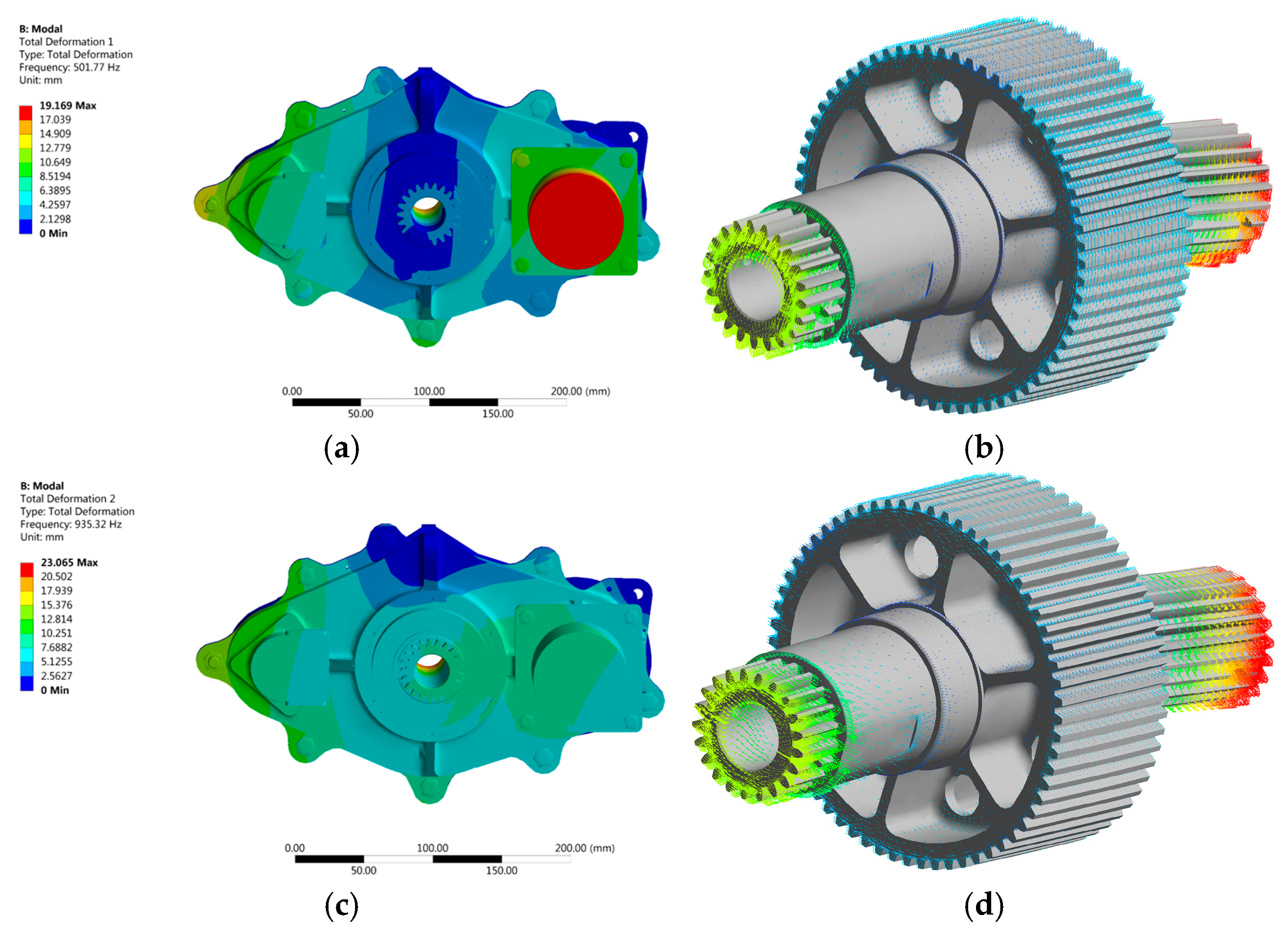
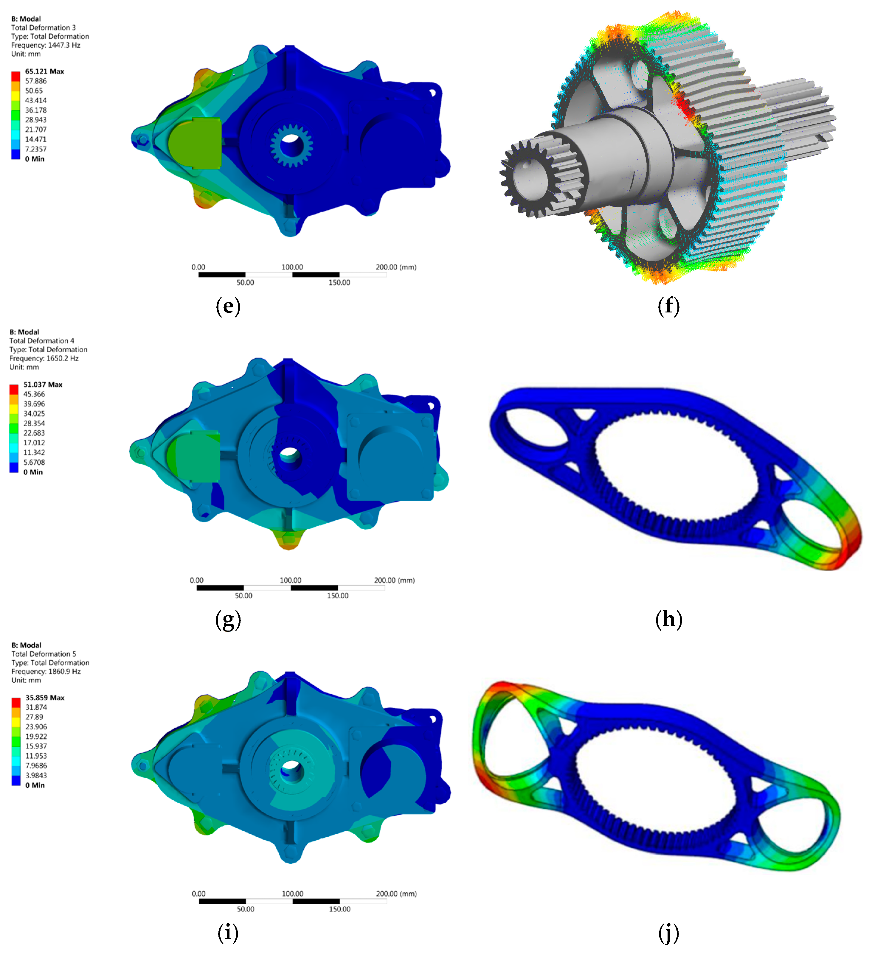
3.2. Modal Frequency Solution of Finite Element Method

Finite element modeling and modal analysis were carried out on the whole model of the aerospace three-ring reducer, including the shell, to obtain the first six orders of modal shapes. Since a modal analysis is conducted in this paper, and taking into account the kinematic characteristics of the inner gear plate and the outer gear, fixed constraints were applied at both ends of the inner gear plate, where the bearings are mounted. Meanwhile, only two translational degrees of freedom were constrained on the outer gear, and torque was applied at the center of the outer gear. In this paper, the Finite Sliding in ANSYS face-to-face contact was utilized to define the contact pairs, and the rated torque was applied to the model for simulation. The modal shapes are shown in Figure 6.

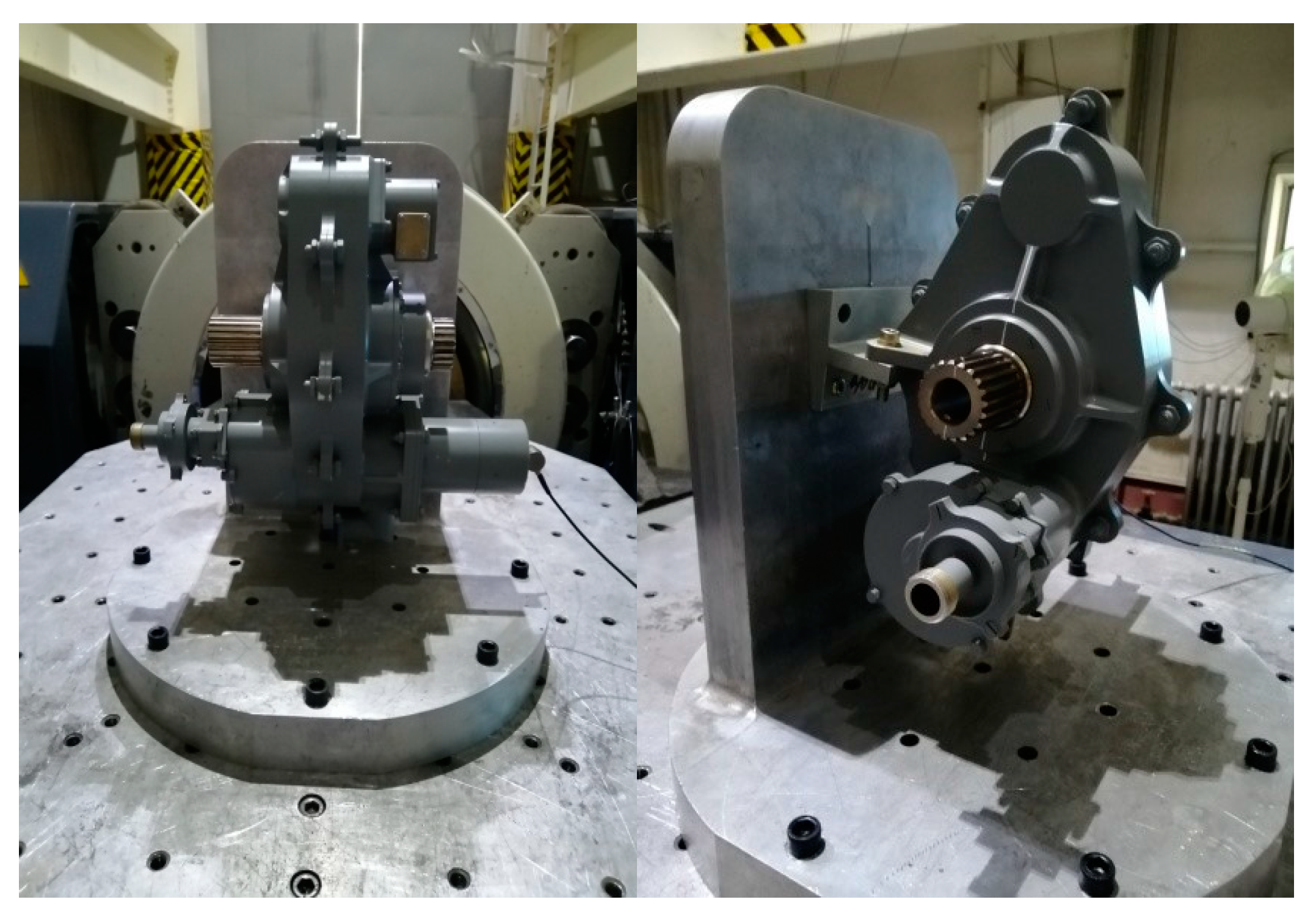
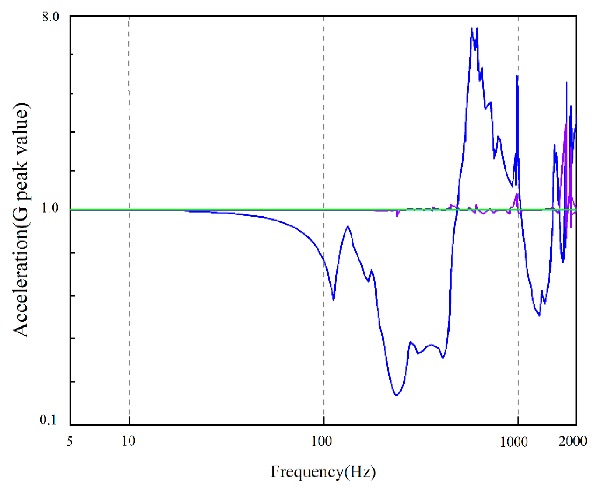
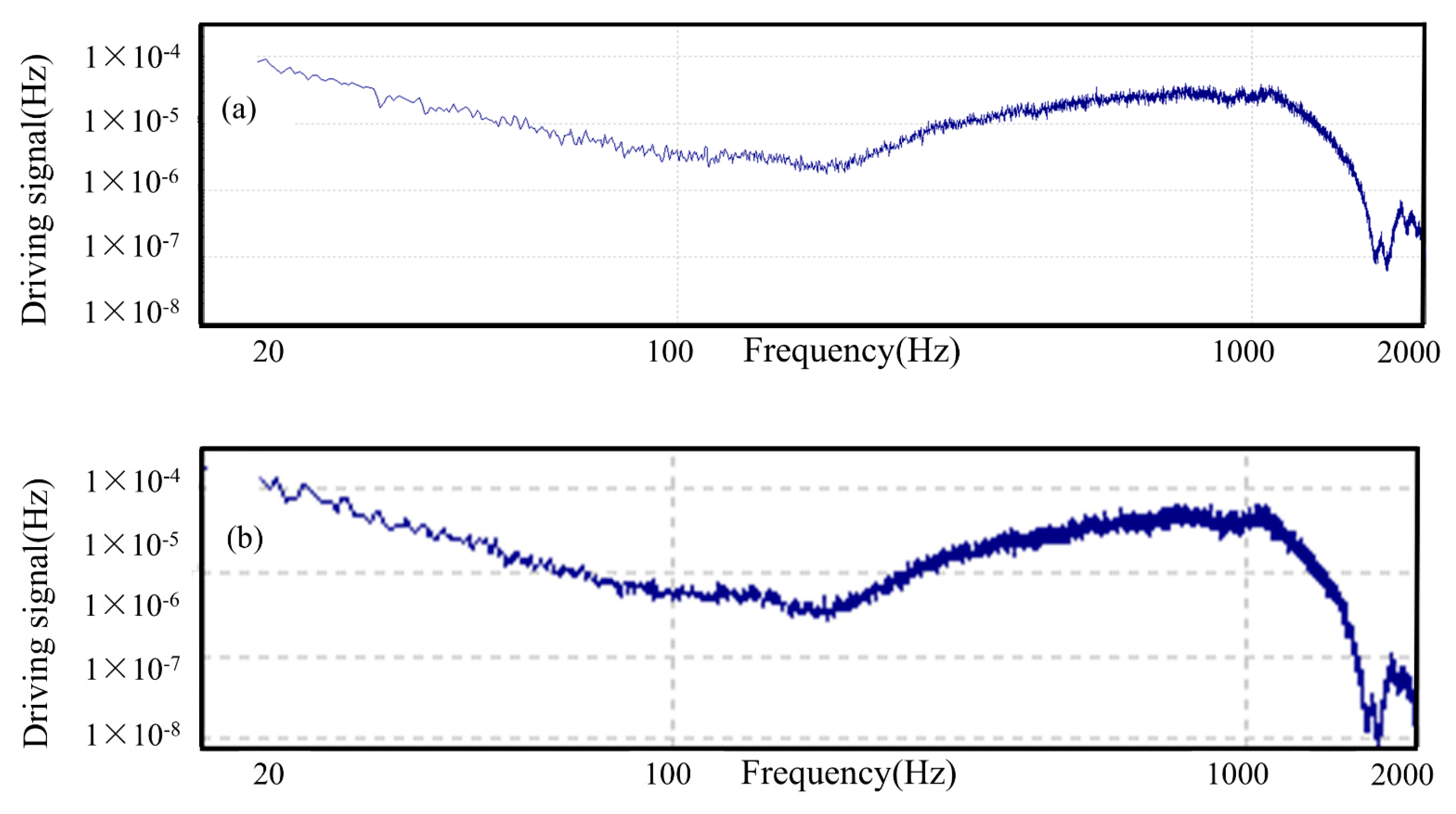
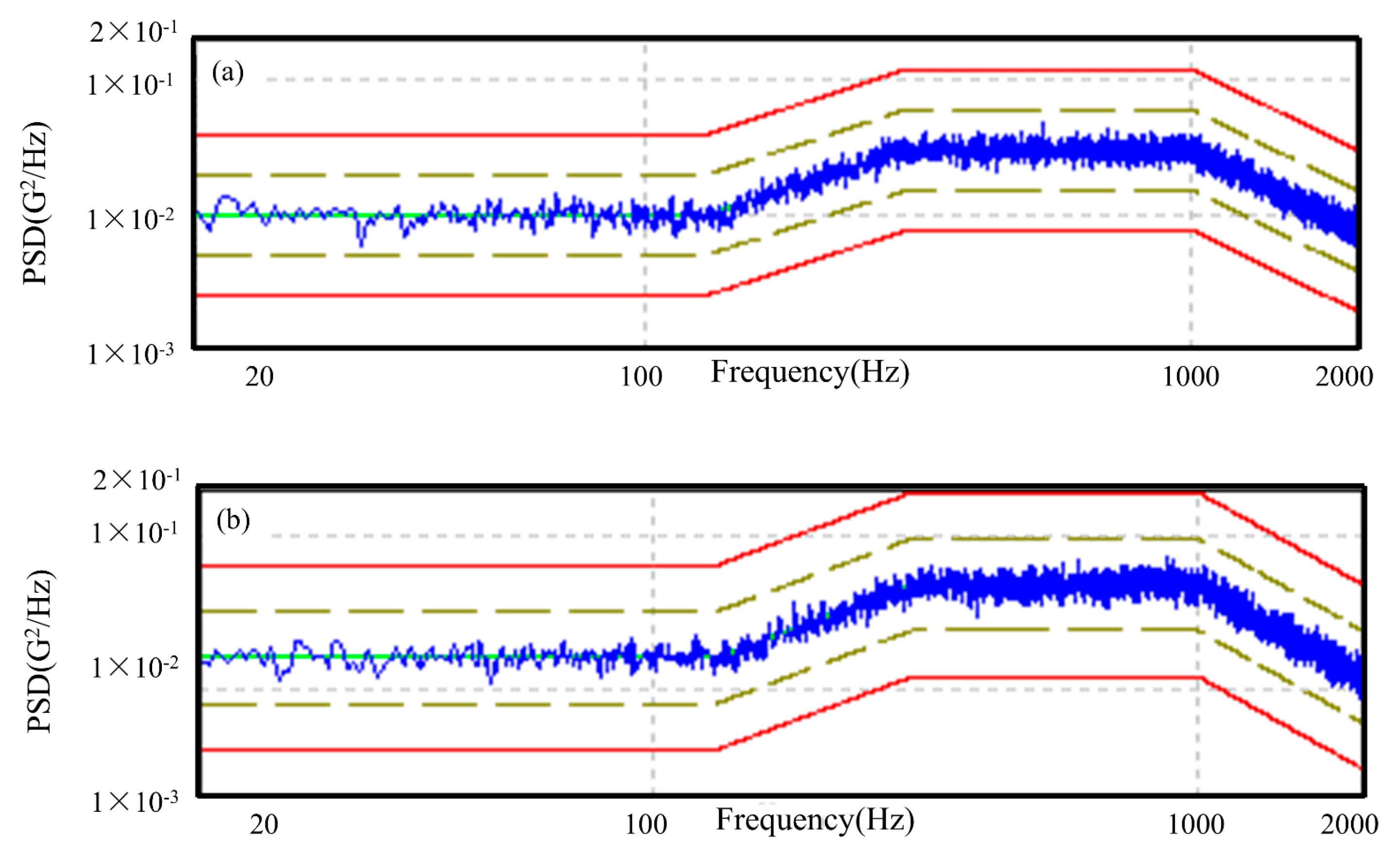
3.3. Experimental Method of Modal Frequency Solving

The modal test method employed the hammering technique, measuring the acceleration response of the aerospace three-ring reducer test piece structure with a vibration meter. This process yields the amplitude frequency characteristic curve of the acceleration frequency response function and determines its natural frequency. The test tapping point was situated near the fixed support end of the structure, while the response point was located at the center of the motor end cover. The installation of the aerospace three-ring reducer on the vibration testing platform is illustrated in Figure 7.
The measured amplitude–frequency characteristic curve of the acceleration frequency response function is shown in Figure 8.
From Figure 8, we can read the peak of the curve to obtain the modal test data of the specimen.
The first–fifth orders of the modal frequencies derived from the dynamical equations, the first–fifth orders of the modal frequencies from the finite element simulation, and the first–fifth orders of the modal frequencies obtained through the experimental method are compared across the three sets of results, as shown in Table 1.
It can be observed that the modal frequencies from the dynamical equations and the finite element simulation, up to 2000 Hz, align well with those obtained from the experimental tests, with errors remaining within the acceptable range. This indicates that the modal results from the dynamical equations and the finite element simulation are accurate, thereby confirming the validity of the dynamic modeling.
The vibration test was conducted on the vibration test platform, based on the maximum value of the vibration amplitude of the components of the aerospace three-ring reducer. The vibration load was applied to the entire machine of the aerospace three-ring reducer to assess the response of the components under this load and to determine whether the aerospace three-ring reducer can continue to operate normally after enduring the vibration load. The vibration test was categorized into the following two conditions: with load and without load. The driving signal for the vibration test was established according to the vibration amplitude derived from the dynamics analysis, and the actual power spectral density curve of the vibration load driving signal applied to the aerospace three-ring reducer via the vibration test platform is illustrated in Figure 9.
After applying the vibration drive signal to the aerospace three-ring reducer, as illustrated in Figure 9, the acceleration power spectral density curves of the vibration response obtained under the two operating conditions are presented in Figure 10.
From the test results, it is evident that, based on the parameters presented in Table 2, the aerospace three-ring reducer is designed to ensure that the vibration response caused by the meshing force, bearing flexibility, and other factors during the meshing process does not impact its normal operation. The vibration displacement, velocity, and acceleration responses of the entire machine remain within a reasonable range throughout the operating frequency band of the reducer (10 Hz to 2000 Hz).

4. Analysis of Dynamic Model Results and Validation by ADAMS-Based Simulation Analysis

4.1. The Solution Method and Result Analysis of Nonlinear Vibration Equation

The 12-degree-of-freedom nonlinear equations presented in Equation (10) can be transformed into first-order differential equations through permutation. By introducing new variables or functions, these higher-order differential equations can be converted into lower-order or first-order forms. This transformation streamlines the process of solving the equations, making the problem more manageable. The fourth-order and fifth-order Runge–Kutta methods are characterized by a high accuracy, the automatic adjustment of the step size based on function changes and required precision, a straightforward procedure, minimal storage requirements, and a stable algorithm. These features provide significant advantages in the real-time analysis and control of the dynamic characteristics of the aerospace three-ring speed reducer, as well as in the rapid optimization of the structural parameters.
The aerospace three-ring reducer used in this study has an input speed of 164.75 r/min and a load torque of 1100 N∙m, and the design parameters are shown in Table 2. The aerospace three-ring reducer was analyzed according to the parameters and the set operating conditions, and the vibration displacement results are shown in Figure 11. The analysis results show that the amplitude of the vibration displacement of the external gear w was 1.5 μm in the x-direction and 2 μm in the y-direction. The amplitude of the vibration displacement of the internal gear plate n1 was 0.6 μm in the x-direction and 3 μm in the y-direction. The vibration displacement amplitude of the internal gear plate n2 was larger, at 15 μm in the x-direction and 15 μm in the y-direction. The vibration displacement amplitude of the internal gear plate n3 was 1.2 μm in the x-direction and 30 μm in the y-direction. The vibration velocity displacement results are shown in Figure 12. The amplitude of the vibration velocity displacement in the torsional direction of the external gear w was 9.77 × 10⁻⁴ rad. The amplitude of vibration angular displacement in the torsion direction of internal gear plate n1 was 5.81 × 10⁻⁶ rad, and the vibration angular displacement amplitude in the torsion direction of internal gear plate n2 was 7.16 × 10⁻⁵ rad. The amplitude of vibration angular displacement in the torsion direction of internal gear plate n3 was 1.0651 × 10⁻⁴ rad. From the analysis results, it can be seen that the amplitude of the vibration displacement in all directions of the output external gear is relatively small compared to the three internal gear plates.
Taking Figure 12a as an example, before 0.007 s, the amplitude of the vibration angular velocity is essentially zero, and then it gradually increases. At 0.014 s, the amplitude of the vibration angular velocity reaches its maximum value, after which it decreases and stabilizes. The angular velocity amplitude of the gear torsional vibration is minimal, while the output gear torsional vibration displacement is the largest, with a maximum value approaching 0.25 m/s2. The time taken for the gear torsional vibration angular velocity to reach a steady state is shorter than that for the other direction, indicating that the torsional vibration angular velocity is smoother than the vibration displacement. Consistent with the results of the vibration displacement response analysis, it is evident that the amplitude of the vibration velocity in each direction of the output outer gear is relatively small, further demonstrating the superiority of the structural design of the aerospace three-ring reducer, which effectively suppresses the vibration of the output shaft.

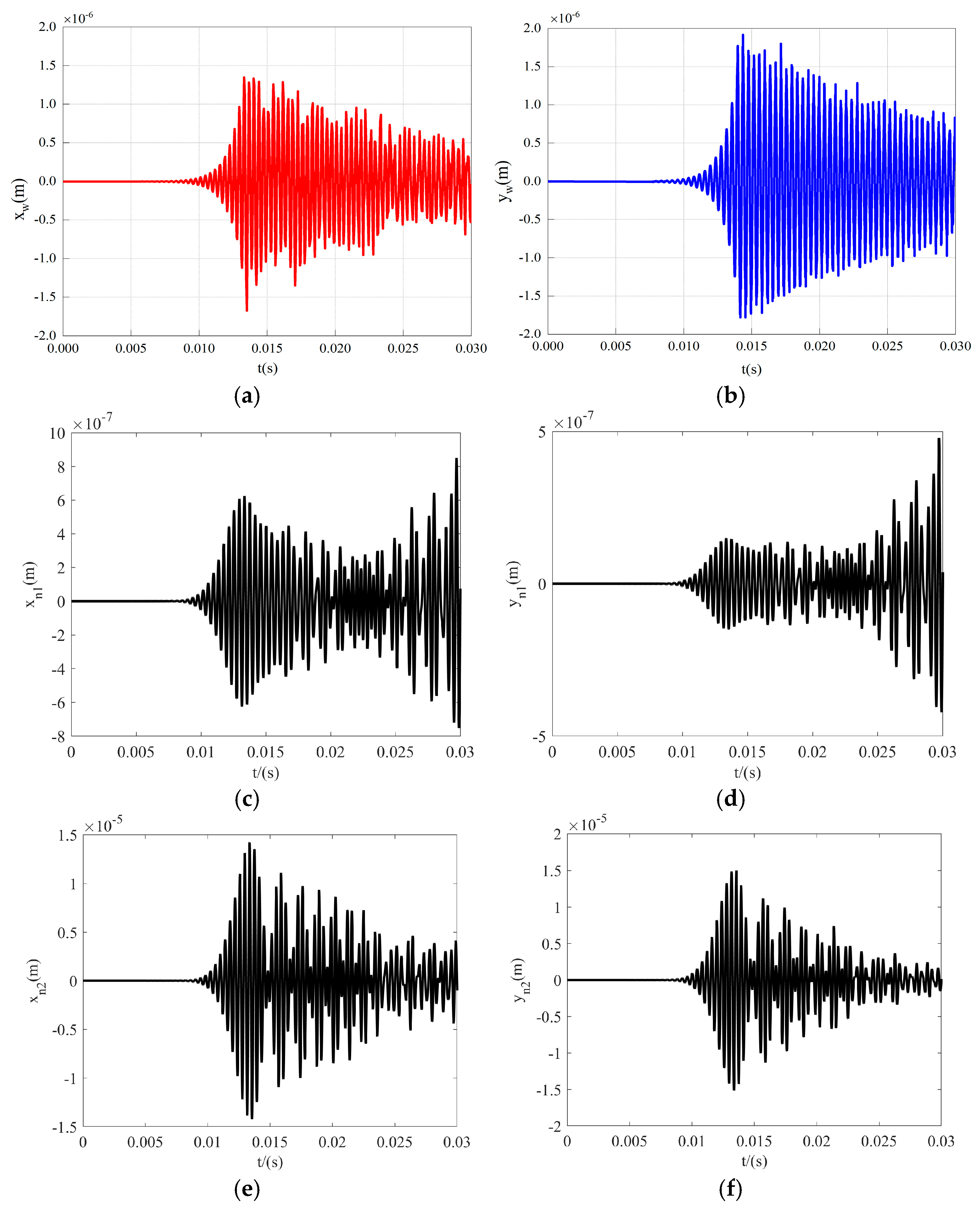
4.2. Vibration Response Analysis

The vibration displacement–velocity phase diagrams for each gear–rotor component of the aerospace three-ring reducer are illustrated in Figure 13. The displacement–velocity phase diagrams for each gear–rotor member appear as repetitive closed curves, while the vibration phase diagrams of the output external gears in the x- and y-directions are notably more regular. This observation confirms the relative stability of the vibration in the output external gears of the three-ring reducer from a lateral perspective. The phase diagrams in all directions originate from the center and spiral outward gradually, indicating that the vibration amplitudes in all directions progressively increase from the initial vibration state. Subsequently, they exhibit irregular and chaotic curves within the closed circle, suggesting that the nonlinear vibration of the aerospace three-ring reducer transitions into a near-chaos and chaotic state after the amplitude stabilizes.
Based on the gear vibration displacement–angular velocity response, illustrated in Figure 11 and Figure 12, the dynamic load of the bearings can be determined by substituting the results into Equation (10). This is depicted in Figure 14, which presents the dynamic loads of the internal gear plate, corresponding to the left and right bearings in the x- and y-directions, respectively.
From Figure 14, it can be seen that the maximum dynamic loads of the bearings in both directions are 3 kN and 1.5 kN, respectively. The dynamic loads of each bearing are periodic impact loads and are basically consistent with the response laws of the gear meshing force and vibration displacement. In addition, the dynamic load amplitudes of each bearing are far smaller than their load dynamic rated values (3.5 KN—tapered roller bearings).

4.3. ADAMS Simulation Condition Parameter Setting

Table 3 presents the kinematic constraints of the components in the three-ring reducer transmission system. Given the numerous bearings in the transmission system and the extensive calculations involved, the model will be simplified without compromising the authenticity. The simplified model is illustrated in Figure 15. The bearings will be constrained by the rotating vice and the sleeve force equivalence. The sleeve force is a flexible force that can be defined with stiffness and damping. The constraint relationship between the gear pair is characterized as the contact, meaning that the normal collision force and tangential friction force constrain one another.

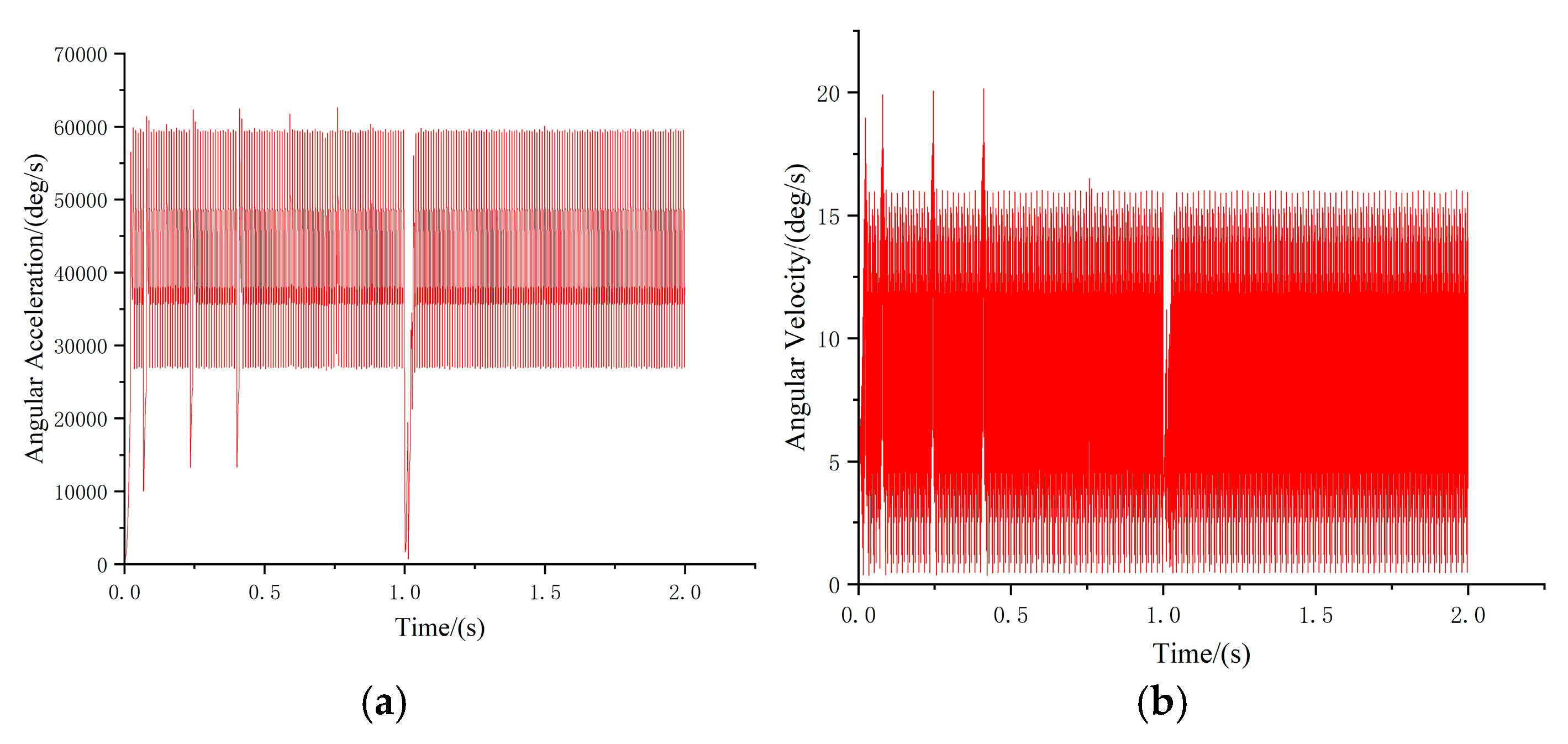
4.4. ADAMS Simulation Analysis Results

Given that the input shaft speed is 360 r/min, the angular velocity and angular acceleration of the output gear shaft are illustrated in Figure 16. As shown in Figure 16, the angular velocity of the output gear shaft consistently varies between 1.4527 and 15.9817. The angular acceleration of the output gear shaft consistently varies between 26,909.8303 and 59,615.0215. This indicates that the virtual prototype operates smoothly, and the simulation motion is successful.
From the simulation process of the meshing force between the output gear shaft and the three internal gears, shown in Figure 17, there are vibration and impact phenomena in the gears during meshing, which are caused by the periodic meshing of the inner and outer gears of the three-ring reducer impacting each other. At the same time, the meshing force also shows steady fluctuations, with the gear meshing force of this three-ring reducer fluctuating up and down with a certain amplitude around an average value during the constant–periodic speed phase.
The combined curves of the output gear shaft angular velocity, angular acceleration, and gear meshing force changes indicate that both the output gear and internal gear disk exhibit stability and fluctuations, although the stability period has been extended. The findings from the ADAMS simulation analysis closely align with the theoretical results discussed previously. This suggests that the symmetrical arrangement of the internal gear plate design in the aerospace three-ring gearhead effectively mitigates the output shaft vibration.

5. Conclusions

This paper studied the dynamic modeling, solution, and validation of the aerospace three-ring gear reducer, and analyzed its dynamic behavior characteristics under the working state. The relevant conclusions are as follows:
(1)
In this paper, the 12-degree-of-freedom nonlinear dynamic equations of the aerospace three-ring reducer gear train were derived and experimentally investigated. By comparing the modal frequencies obtained from the experimental values, finite element values, and dynamical equations (Table 1), it is evident that the finite element values within 2000 Hz align with the modal frequencies obtained from experiments, with the error remaining within the permissible range. This indicates that the dynamic model established in this paper is accurate and effectively reflects the vibration characteristics of the aerospace three-ring reducer gear.
(2)
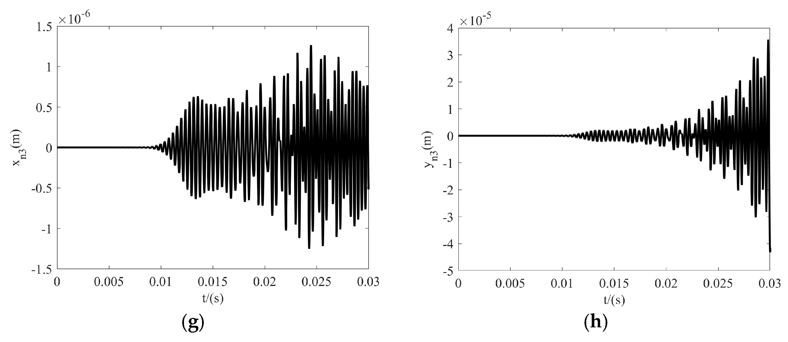
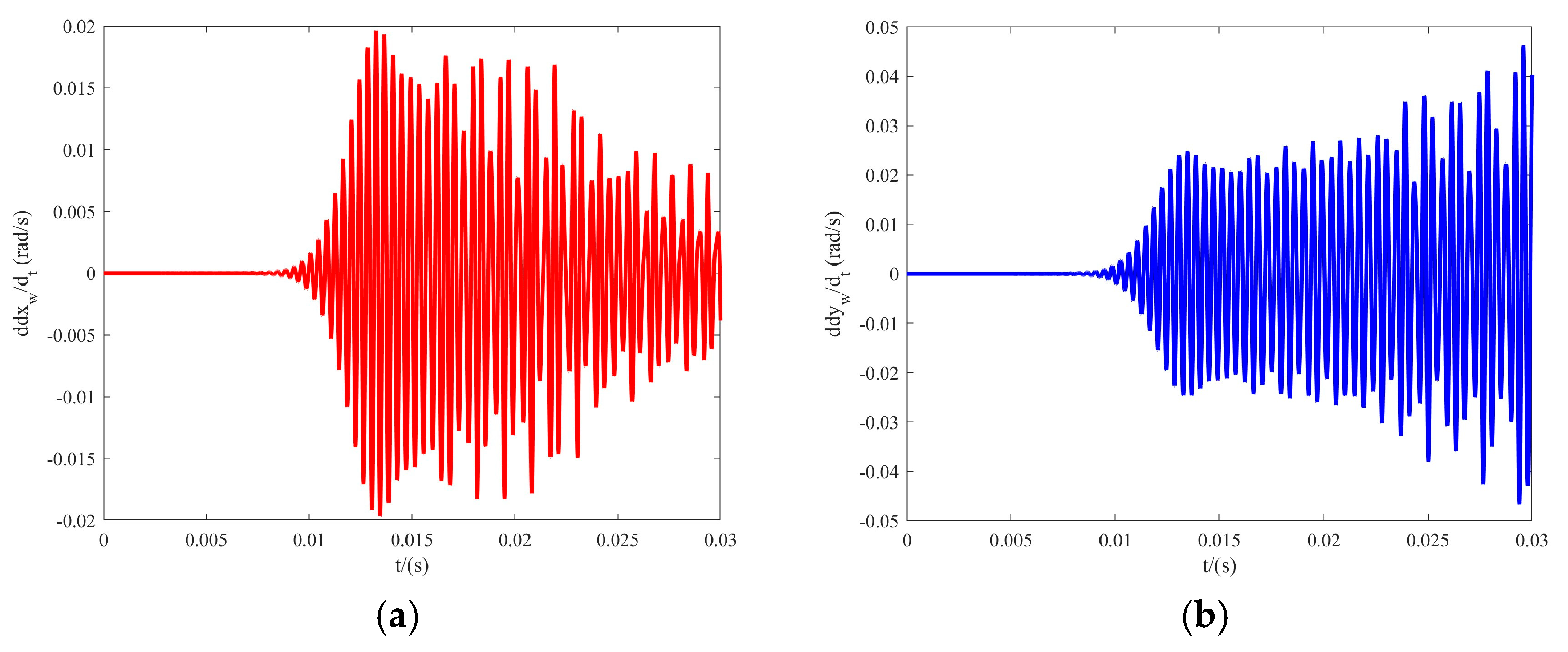
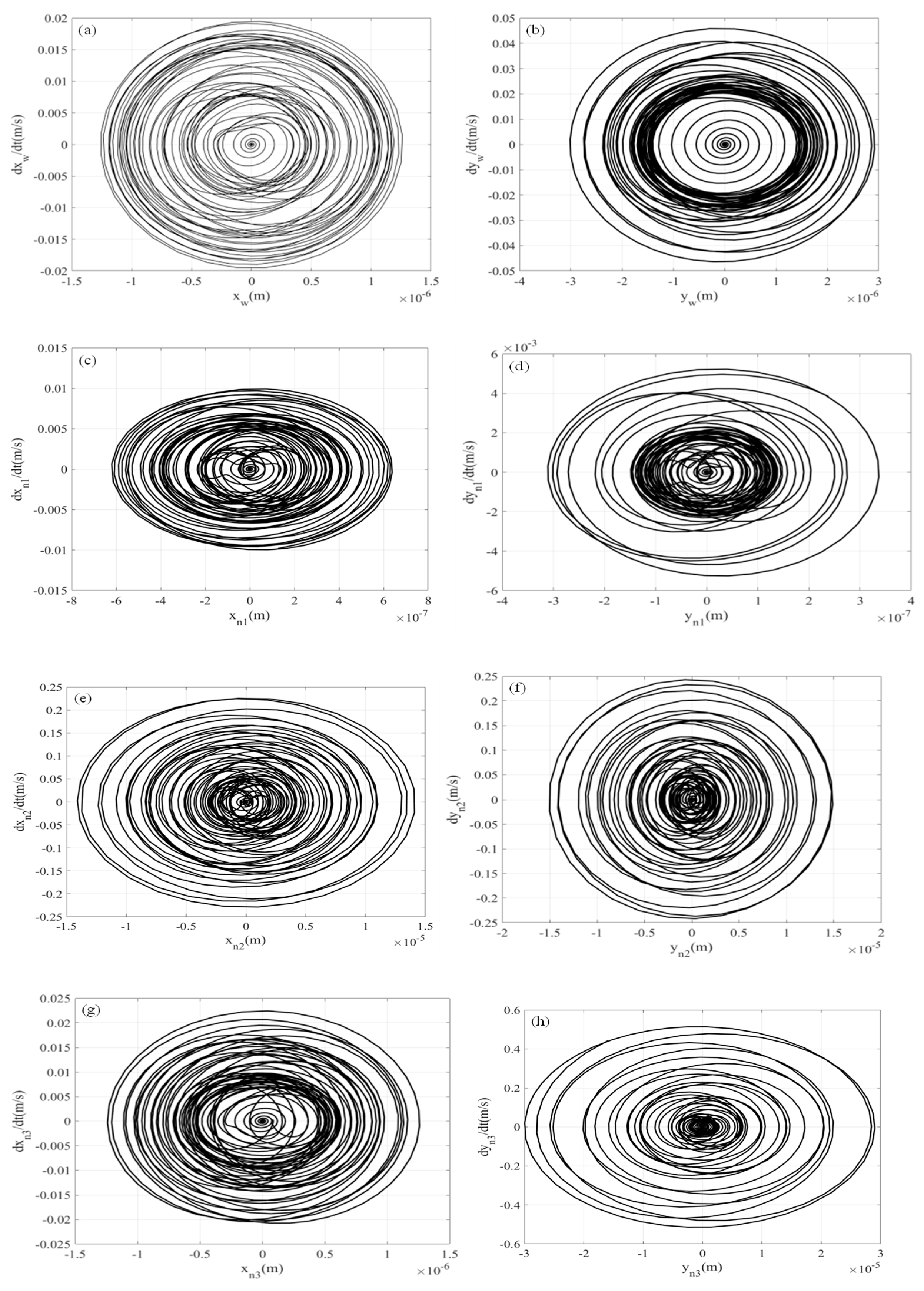
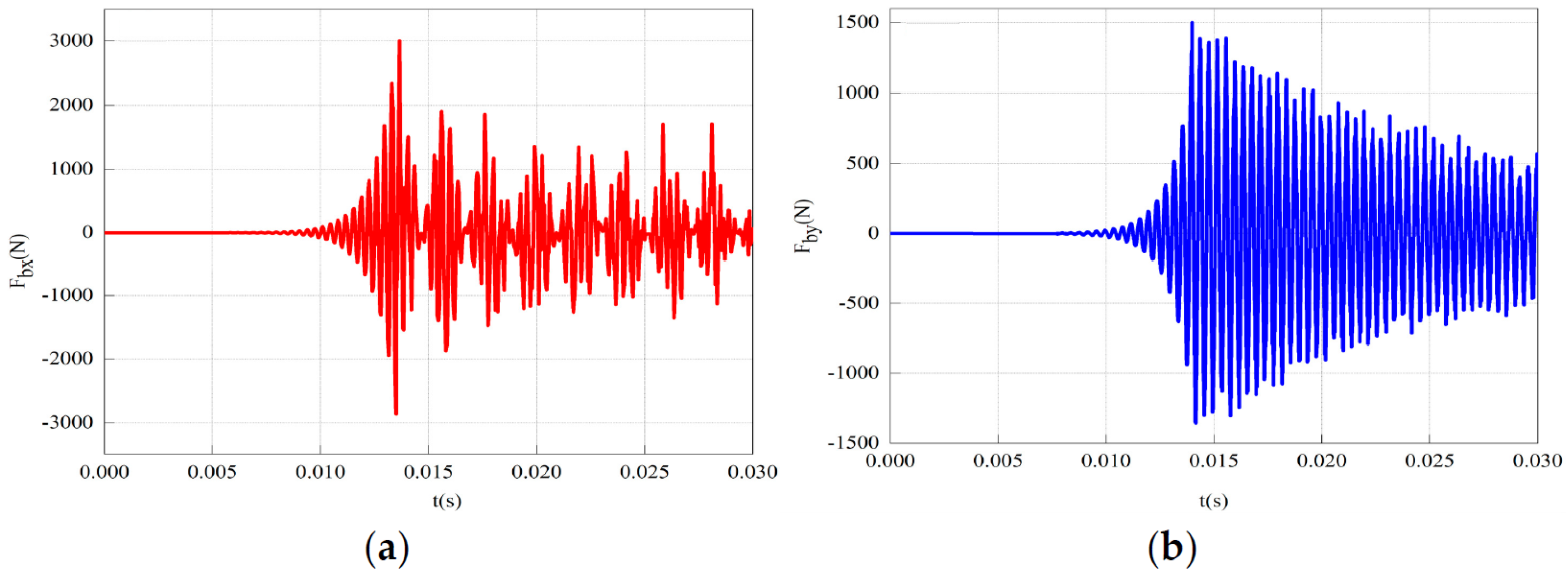
The vibration displacement amplitude and angular velocity amplitude of the output gear in all directions are relatively small compared to the inner gear plate. The vibration gradually increases to its maximum value after being excited, then decreases and stabilizes. The displacement–velocity phase diagrams of each gear–rotor component exhibit repeated closed curves, while the vibration phase diagrams of the output outer gear in the x- and y-directions are notably more regular, confirming the relative stability of the output outer gear’s vibration in the three-ring gearbox from the side. Coupled with the ADAMS simulation results, the speed and acceleration curves of the output external gear exhibit both stability and fluctuations, while the force curves on the three internal gear plates also reveal stability and fluctuations. However, in both instances, the duration of the stable period exceeds that of the fluctuating period. This shows that the vibration of the aerospace three-ring reducer is small, can bear large loads, and is suitable for high-speed and heavy-duty occasions.

Author Contributions

L.L., J.L. and S.C. conceived the presented idea. L.L. and G.L. established an overall paper research framework and the model. L.L. and S.C. conducted data calculation for the overall paper. L.L. and J.L. supervised the findings of this work. L.L., J.L. and G.L. collected and provided the model data. All authors have read and agreed to the published version of the manuscript.

Funding

This work was supported by the Young Doctor Foundation Project of higher education institutions in Gansu Province (2022QB-048), the Science and Technology Project of the Gansu Province Natural Science Foundation (22JR5RA291) and Sichuan Science and Technology Program (Grant No. 2023NSFSC0855), the National Natural Science Foundation of China (Grant No. 52105058), the Innovation Project of Lanzhou Youth Science and Technology Talent (No. 2023-QN-43), and the Open Fund of Hubei Key Laboratory of Mechanical Transmission and Manufacturing Engineering at Wuhan University of Science and Technology (MTMEOF2022B03).

Institutional Review Board Statement

Not applicable.

Informed Consent Statement

Not applicable.

Data Availability Statement

The data presented in this study are available on request from the corresponding author

Conflicts of Interest

Authors Jinyong Lai, Lan Luo, and Shiyuan Chao was employed by the company Lanzhou Wanli Aviation Electromechanical Co., Ltd. The remaining author declare that the research was conducted in the absence of any commercial or financial relationships that could be construed as a potential conflict of interest.

References

  1. Shi, Z. Multi-Variable Coupling Nonlinear Dynamic Characteristics Research on A Planetary Reducer with Small Tooth Number Difference. Master’s Thesis, Chongqing University, Chongqing, China, 2015. (In Chinese). [Google Scholar]
  2. Wang, J.; Li, Q.; Xiao, K.; Shi, Z. Research on nonlinear coupled vibration of planet reducer with fewer tooth difference. J. Huazhong Univ. Sci. Technol. (Nat. Sci. Ed.) 2016, 44, 40–46. (In Chinese) [Google Scholar]
  3. Yang, H. Analysis of Transmission Precision of Reducing Mechanism for Actuator with Small Tooth Number Difference. Master’s Thesis, Chongqing University, Chongqing, China, 2018. (In Chinese). [Google Scholar]
  4. Zhang, J. Research on Dynamic Characteristics of NN Planetary Gear Servo Drive System with Small Tooth Difference. Master’s Thesis, Chongqing University, Chongqing, China, 2016. (In Chinese). [Google Scholar]
  5. Fakhfakh, H.; Bruyère, J.; Velex, P.; Becquerelle, S. A torsional model of multistage gears influence of external excitations and tooth shape modifications. Mech. Ind. 2016, 17, 413–420. [Google Scholar] [CrossRef]
  6. Wang, S.Y.; Zhu, R.P. Nonlinear torsional dynamics of star gearing transmission system of GTF gearbox. Shock Vib. 2020, 2020, 1–15. [Google Scholar] [CrossRef]
  7. Zhao, M.M.; Ji, J.C. Nonlinear torsional vibrations of a wind turbine gearbox. Appl. Math. Model. 2015, 39, 4928–4950. [Google Scholar] [CrossRef]
  8. Yang, J.; Zhang, C.; Qin, D. Elastic dynamics analysis of three-ring reducer. J. Mech. Eng. 2010, 54–58. [Google Scholar]
  9. Wang, J.; Li, Q.; Xiao, K.; Shi, Z. Study on nonlinear coupled vibration of planetary reducer with small tooth difference. Huazhong Univ. Sci. Technol. J. 2016, 44, 40–46. [Google Scholar]
  10. Zhou, W.; Zhu, R.; Liu, W.; Shang, Y. An Improved Dynamic Transmission Error Model Applied on Coupling Analysis of Gear Dynamics and Electrohydrodynamic Lubrication. J. Tribol. 2022, 144, 051601. [Google Scholar] [CrossRef]
  11. Wang, Y.; Hood, A.A.; Cooley, C.G. Finite element/contact mechanics analysis of spur gear pairs with tooth root cracks. In Proceedings of the ASME 2021 International Design Engineering Technical Conferences and Computers and Information in Engineering Conference, Virtual, 17–19 August 2021; Volume 10, p. V010T10A024. [Google Scholar]
  12. Kumar, R.; Roy, S.K. Model-based diagnostic tool for detection of gear tooth crack in a wind turbine gearbox under constant load. Int. J. Syst. Assur. Eng. Manag. 2022, 13, 1666–1687. [Google Scholar] [CrossRef]
  13. Zhai, H.; Zhu, C.; Song, C.; Liu, H.; Bai, H. Influences of carrier assembly errors on the dynamic characteristics for wind turbine gearbox. Mech. Mach. Theory 2016, 103, 138–147. [Google Scholar] [CrossRef]
  14. Sanjib, C.; Rama, K. Vibration of high-speed helical geared shaft systems mounted on rigid bearings. Int. J. Mech. Sci. 2018, 142–143, 176–190. [Google Scholar]
  15. Zhang, H. Design of New Type Involute Planetary Gear Reducer of Small Tooth Number Difference. Adv. Mater. Res. 2012, 490, 2076–2080. [Google Scholar] [CrossRef]
  16. Huang, C.; Wang, J.X.; Xiao, K.; Li, M.; Li, J.Y. Dynamic characteristics analysis and experimental research on a new type planetary gear apparatus with small tooth number difference. J. Mech. Sci. Technol. 2013, 27, 1233–1244. [Google Scholar] [CrossRef]
  17. Huang, C.; Huang, B.; Zhang, Y.; Xiao, K. Modal analysis and experimental research on a planetary reducer with small tooth number difference. Trans. Can. Soc. Mech. Eng. 2019, 44, 202–212. [Google Scholar] [CrossRef]
  18. Hu, Y.; Shao, Y.; Chen, Z.; Zuo, M.J. Transient meshing performance of gears with different modification coefficients and helical angles using explicit dynamic FEA. Mech. Syst. Signal Process. 2011, 25, 1786–1802. [Google Scholar] [CrossRef]
  19. Wang, P.Y.; Cai, X.L. Vibrational analysis of planetary gear trains by finite element method. Appl. Mech. Mater. 2013, 284–287, 1012–1017. [Google Scholar] [CrossRef]
  20. Tristan, M.E.; Robert, G.P. Planetary gear modal vibration experiments and correlation against lumped-parameter and finite element models. J. Sound Vib. 2013, 332, 2350–2375. [Google Scholar]
  21. Huang, Q.B.; Li, X. Modal Analysis on Tooth Ring Plate of Three-Ring Gear Reducer. Appl. Mech. Mater. 2013, 345, 124–127. [Google Scholar] [CrossRef]
  22. Liu, Y.K.; Wei, Y.L. The Performance Study of Three-Ring Gear Reducer. Adv. Mater. Res. 2013, 605, 1261–1264. [Google Scholar] [CrossRef]
  23. Yang, H.B.; Wang, Q. Three-ring gear reducer Internal tooth plate processing method in the research and analysis. Appl. Mech. Mater. 2014, 472, 312–315. [Google Scholar] [CrossRef]
  24. Tong, Y. Research on Multi Body Dynamics of Three-ring Reducer with Small Tooth Difference for Aero Electromechanical Actuator. Master’s Thesis, Lanzhou University of Technology, Lanzhou, China, 2021. (In Chinese). [Google Scholar]
  25. Du, W. Study on Dynamic Analysis and Simulation of Three-Ring Reducer Based on Dynamic Balance. Northeast Petroleum University: Daqing, China, 2020. (In Chinese) [Google Scholar]
  26. Zhou, Y. Research on Mechanical Properties and Optimization of Structure Parameters for Three-ring Gear Reducer. Master’s Thesis, Northeast Petroleum University, Daqing, China, 2016. (In Chinese). [Google Scholar]
  27. Wen, F.; Pang, Y.; Chen, J.; Liu, W. Study on the Dynamics Characteristic of Three-ring Gear Reducer with Thermo-elastic Coupling. J. Mech. Transm. 2015, 39, 22–25. (In Chinese) [Google Scholar]
  28. Zhao, Z. The Dynamics Analysis and Simulation Investigation of the Three-ring Gear Reducer Based on Virtual Prototyping Technology. Master’s Thesis, Northeast Petroleum University, Daqing, China, 2016. (In Chinese). [Google Scholar]
  29. Liu, G.; Lu, Z.R.; Wang, L.; Liu, J.K. A new semi-analytical technique for nonlinear systems based on response sensitivity analysis. Nonlinear Dyn. 2021, 103, 1529–1551. [Google Scholar] [CrossRef]
  30. Liu, G.; Liu, J.K.; Wang, L.; Lu, Z.R. A new semi-analytical approach for quasi-periodic vibrations of nonlinear systems. Commun. Nonlinear Sci. Numer. Simul. 2021, 103, 105999. [Google Scholar] [CrossRef]
  31. Liu, G.; Liu, J.K.; Wang, L.; Lu, Z.R. Time-domain minimum residual method combined with energy balance for nonlinear conservative systems. Mech. Syst. Signal Process. 2022, 170, 108818. [Google Scholar] [CrossRef]
  32. Liu, G.; Liu, J.K.; Lu, Z.R. High-precision semi-analytical solution for the quasi-periodic nanobeam system based on the weight time-domain minimum residual method. Compos. Struct. 2023, 323, 117457. [Google Scholar] [CrossRef]
  33. Li, S.; Zhang, Z.; Dong, J. Load sharing characteristics of multistate planetary gear train using analytical and finite element mode. Int. J. Comput. Appl. Technol. 2016, 53, 107–120. [Google Scholar] [CrossRef]
  34. Zhang, T.; Wu, Y.; Wu, J. Contact finite element analysis of the influence of manufacturing error on gear pair meshing. Vib. Shock 2015, 34, 43–50. [Google Scholar]
Figure 1. Three-dimensional assembly model of the aerospace three-ring reducer.
Aerospace 11 01049 g001
Figure 2. Aerospace three-ring reducer three-dimensional assembly model exploded drawing.
Aerospace 11 01049 g002
Figure 3. Dynamic model of the aerospace three-ring gear reducer.
Aerospace 11 01049 g003
Figure 4. Displacement of the meshing point.
Aerospace 11 01049 g004
Figure 5. The computation of the meshing stiffness utilizing the Ishikawa method.
Aerospace 11 01049 g005
Figure 6. The first–fifth-order modal shapes of the aerospace three-ring reducer. (a) The first-order modal shape of the shell. (b) The first-order modal shape of the external gear. (c) The second-order modal shape of the shell. (d) The second-order modal shape of the external gear. (e) The third-order modal shape of the shell. (f) The third-order modal shape of the external gear. (g) The fourth-order modal shape of the shell. (h) The second-order modal shape of the internal gear. (i) The fifth-order modal shape of the shell. (j) The third-order modal shape of the internal gear.
Aerospace 11 01049 g006aAerospace 11 01049 g006b
Figure 7. Vibration test and installation of the aerospace three-ring reducer.
Aerospace 11 01049 g007
Figure 8. Amplitude–frequency characteristic curve of the aerospace three-ring reducer.
Aerospace 11 01049 g008
Figure 9. Power spectral density curve of driving signal. (a) No-load condition drive signal. (b) Load condition drive signal.
Aerospace 11 01049 g009
Figure 10. Power spectral density curve of vibration response acceleration. (a) Vibration response curve (unloading). (b) Vibration response curve (loading).
Aerospace 11 01049 g010
Figure 11. Vibration displacement response of transmission system. (a) Vibration displacement response of the external gear w in the x-direction. (b) Vibration displacement response of the external gear w in the y-direction. (c) Vibration displacement response of the internal gear plate n1 in the x-direction. (d) Vibration displacement response of the internal gear plate n1 in the y-direction. (e) Vibration displacement response of the internal gear plate n2 in the x-direction. (f) Vibration displacement response of the internal gear plate n2 in the y-direction. (g) Vibration displacement response of the internal gear plate n3 in the x-direction. (h) Vibration displacement response of the internal gear plate n3 in the y-direction.
Aerospace 11 01049 g011aAerospace 11 01049 g011b
Figure 12. Amplitude of the angular velocity of the transmission system. (a) Vibration velocity amplitude of the external gear w in the x-direction. (b) Vibration velocity amplitude of the external gear w in the y-direction. (c) Vibration velocity amplitude of the internal gear plate n1 in the x-direction. (d) Vibration velocity amplitude of the internal gear plate n1 in the y-direction. (e) Vibration velocity amplitude of the internal gear plate n2 in the x-direction. (f) Vibration velocity amplitude of the internal gear plate n2 in the y-direction. (g) Vibration velocity amplitude of the internal gear plate n3 in the x-direction. (h) Vibration velocity amplitude of the internal gear plate n3 in the y-direction.
Aerospace 11 01049 g012aAerospace 11 01049 g012b
Figure 13. Vibrational displacement–velocity phase diagram. (a) Displacement–velocity phase diagram of the external gear w in the x-direction. (b) Displacement–velocity phase diagram of the external gear w in the y-direction. (c) Displacement–velocity phase diagram of the internal gear n1 in the x-direction. (d) Displacement–velocity phase diagram of the internal gear n1 in the y-direction. (e) Displacement–velocity phase diagram of the internal gear n2 in the x-direction. (f) Displacement–velocity phase diagram of the internal gear n2 in the y-direction. (g) Displacement–velocity phase diagram of the internal gear n3 in the x-direction. (h) Displacement–velocity phase diagram of the internal gear n3 in the y-direction.
Aerospace 11 01049 g013
Figure 14. Dynamic load of internal gear plate bearing. (a) Dynamic load in the x-direction for the internal gear plate bearings. (b) Dynamic load in the y-direction for the internal gear plate bearings.
Aerospace 11 01049 g014
Figure 15. Three-ring reducer simplified model.
Aerospace 11 01049 g015
Figure 16. Output gear shaft angular acceleration and angular velocity simulation results. (a) Angular acceleration curve. (b) Angular velocity curve.
Aerospace 11 01049 g016
Figure 17. Simulation results of the meshing force between the output gear shaft and internal gear. (a) Internal gear 1. (b) Internal gear 2. (c) Internal gear 3.
Aerospace 11 01049 g017
Table 1. Modal testing results.
OrderVibration Characteristic Equation (Hz)Finite Element
(Hz)
Experimental Method (Hz)
1529.83501.77582
2976.51935.32977
31487.141447.31487
41727.931650.21747
51862.311860.91839
Table 2. Design parameters of the aerospace three-ring reducer.
Design ParametersExternal Gear WInternal Gear Plate n1, n2, and n3
m (mm)22
Z6364
X−0.10.25
ha*0.70.7
c*0.250.2
m0 (kg)4.1250.961
I0 (kg∙m2)0.0060.007
lb (mm)107
R (mm)1.51
kb/(108 N/m−1)1.54.4
cb/(105 N/s/m−1)2.12.3
km/(108 N/m−1)3.58543.9547
cm/(N/s/m−1)566.1293687.1411
Table 3. Constraint relationship in a three-ring reducer transmission system.
ComponentsConstraint Type
Input ShaftGroundRevolute Pair
Supporting ShaftGroundRevolute Pair
Gear ShaftGroundRevolute Pair
Input ShaftInternal GearRevolute Pair
Supporting ShaftInternal GearRevolute Pair
Gear shaftInternal GearContact
Disclaimer/Publisher’s Note: The statements, opinions and data contained in all publications are solely those of the individual author(s) and contributor(s) and not of MDPI and/or the editor(s). MDPI and/or the editor(s) disclaim responsibility for any injury to people or property resulting from any ideas, methods, instructions or products referred to in the content.

