1. Introduction
In FMCW radar systems, mutual coupling or leakage between the Tx and Rx antennas introduces a false echo at zero range, limiting receiver sensitivity and reducing long-range detection performance [
1,
2]. This diminishes the signal-to-noise ratio (SNR) and reduces the maximum detectable range. Moreover, leaked Tx phase noise degrades detection performance for space debris with low relative velocities (a few m/s). In such scenarios, the low-frequency Doppler component (a few Hz) is masked by the phase noise, necessitating longer frequency sweeps, which increase energy consumption and demand greater DSP power and memory for signal processing [
3,
4].
Addressing Tx/Rx interference is a critical challenge for the ranging radar system in the ClearSpace Active Debris Removal mission [
5]. In this mission, the antennas are separated by several tens of wavelengths and mounted on metallic satellite platforms. Leakage suppression is essential to prevent the formation of surface currents on the metallic platform and their propagation toward the receiver. Additionally, the system must interact with incident space waves, which impinge at various angles (parallel, oblique, and normal). The effective attenuation of interference is required across the radar’s 5% bandwidth. The radar operates in the X-band with a central chirp frequency of 9.5 GHz.
Various techniques have been proposed to improve Tx/Rx isolation. For instance, enclosing antennas with 50 mm baffles has been shown to enhance isolation by up to 10 dB in the frequency range of 9.3–9.4 GHz [
6]. Another approach involves using wave-absorbing materials, with their placement optimized through electromagnetic field analysis methods, such as generalized impedance density theory and Poynting vector methods [
7]. However, these physical isolation methods are often unsuitable for space applications due to size and weight requirements and compatibility with the space environment. Wave absorbers may degrade under extreme temperatures [
8], fail under radiation exposure, out-gas in a vacuum, risking the contamination of sensitive satellite components [
9].
Active cancellation techniques, widely employed in FMCW radars, provide another solution by introducing additional hardware to suppress coupling between antennas [
10,
11]. However, canceling multiple path lengths requires multiple cancellation channels, increasing system size, weight, and power (SWaP) requirements and costs, making this approach impractical for many satellite applications.
Metamaterials (MMs) offer a promising alternative solution to improve Tx/Rx isolation. MMs can be categorized into planar (2D) and non-planar (3D) structures. While non-planar MMs, such as multilayered designs [
12], corrugated surfaces [
13], and pyramidal structures [
14], offer wideband suppression, they are generally unsuitable for space applications due to their complexity and size, weight, and power (SWaP) constraints. Conversely, planar MMs, fabricated using PCB technology, are lightweight, reliable, and well suited for space applications.
Planar MMs have been extensively employed in applications such as improving the isolation of antennas in single-board radar systems [
15] and planar MIMO systems [
16,
17,
18]. In these applications, the primary focus of the design is to suppress slow-wave propagation, which is the dominant leakage mechanism in conventional systems. For instance, in [
15], planar electromagnetic bandgap (EBG) structures were used to enhance isolation in FMCW radar systems (57–64 GHz) with Tx/Rx fabricated on the same substrate with separations of 3
.
Another application of MMs is radar cross-section (RCS) reduction, where the goal is to attenuate waves striking the surface at normal or oblique angles [
19,
20]. In such cases, the structure was designed to reflect waves with an inverse phase, effectively canceling the incident waves.
A limitation of conventional planar metamaterial (MM) designs, such as electromagnetic bandgap (EBG) structures, is that the energy stored within the structure partially dissipates through ohmic losses, while a significant portion propagates along the cells. When this propagating energy encounters border cells, it may be either reflected back or re-radiated. The re-radiated energy can then propagate and be absorbed by the receiver antenna, leading to decreased isolation. In [
21], a circuit-based nonlinear metasurface absorber is proposed to effectively suppress leakage in such scenarios for high-power applications. In this concept, MMs are designed with a series of rectification diodes to attenuate the RF energy stored within the MMs. Furthermore, in this research, as the antennas are positioned slightly above the platform, leakage can also occur in the form of lateral waves propagating parallel to the metallic platform. So, the optimized design must engage with all sorts of leakage.
This research addresses these limitations by proposing two planar metamaterial-based solutions optimized to suppress slow-wave propagation and re-direct radiated energy normal to the surface. A novel compact EBG design with a cell length of 3 mm and a non-uniform high-impedance surface (HIS) array are introduced to improve isolation between 9.3–9.8 GHz. The design procedures for both MMs are explained in detail. As mentioned, these solutions are specifically tailored to meet the unique challenges of the ClearSpace mission, providing enhanced Tx/Rx isolation. Measurement results confirm the effectiveness of these designs in improving isolation, highlighting their potential for satellite radar applications.
2. Design Wideband Meta-Materials for Antenna Decoupling
As mentioned earlier, the metallic plate beneath the Tx/Rx antenna supports wave propagation by inducing surface currents on the metallic platform. At the edge of the patch antenna, the surface wave in the antenna’s substrate re-radiates, and a portion of this radiated energy propagates as a bounded wave toward the receiver. This bounded wave is re-scattered when encountering discontinuities or surface textures along its path. As a result, the bounded wave reaches the Rx antenna and enters the receiver [
22]. In addition, a portion of the radiated energy leaks directly into space as lateral wave propagation, which needs to be attenuated. Therefore, the MM should be designed to interact with lateral space waves, re-radiating or redirecting them away to prevent interference with the receiver.
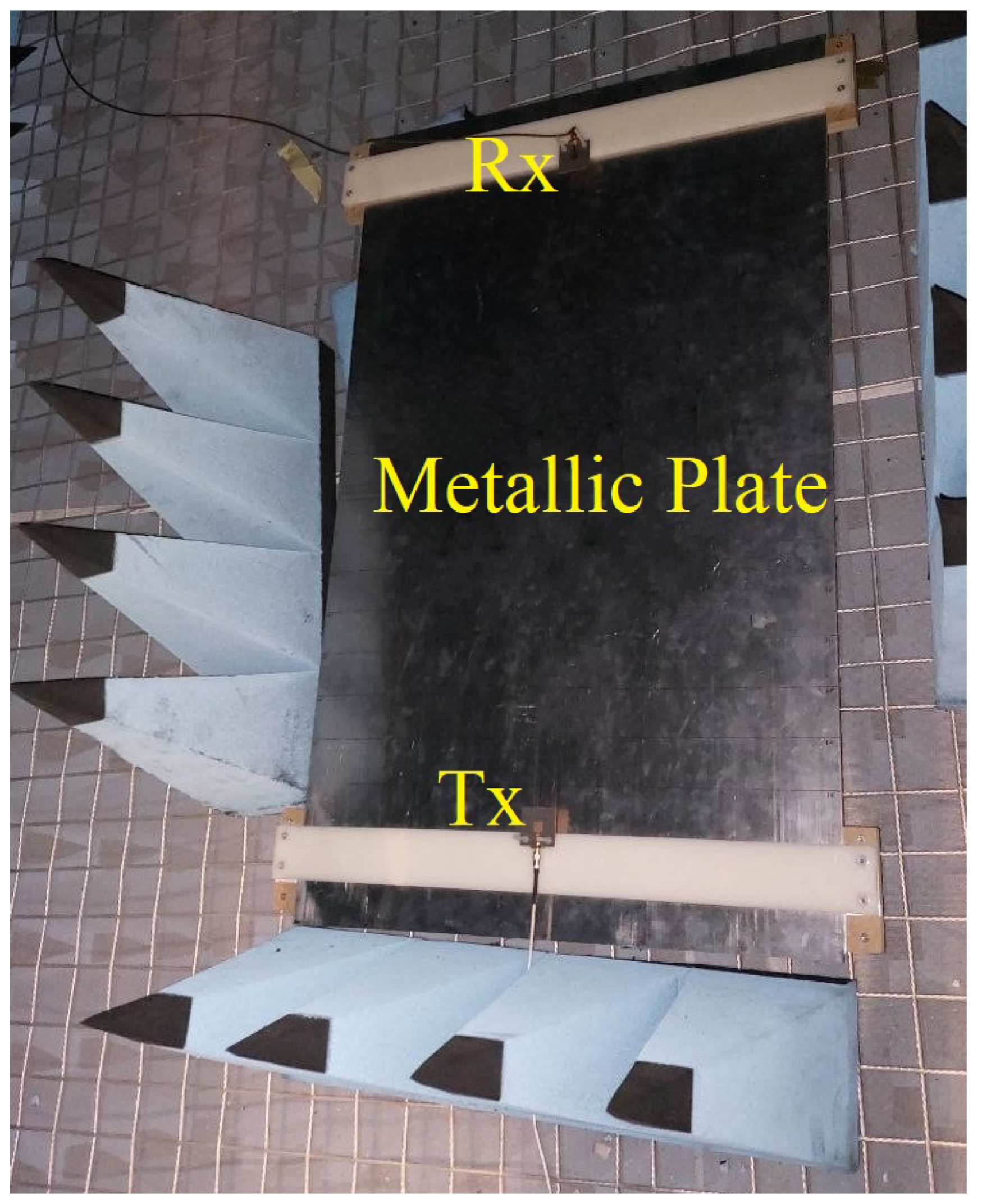
Two distinct metasurfaces, high-impedance surface (HIS) and electromagnetic bandgap (EBG) structures, have been designed to effectively reduce leakage between the Tx and Rx patch antennas. In this study, the Tx and Rx antennas were positioned on a metallic surface with a fixed separation distance of 800 mm, representing the antenna placement on the metallic side of the satellite cube in the primary design of ClearSpace. Both antennas were mounted 16 mm above the metallic surface (
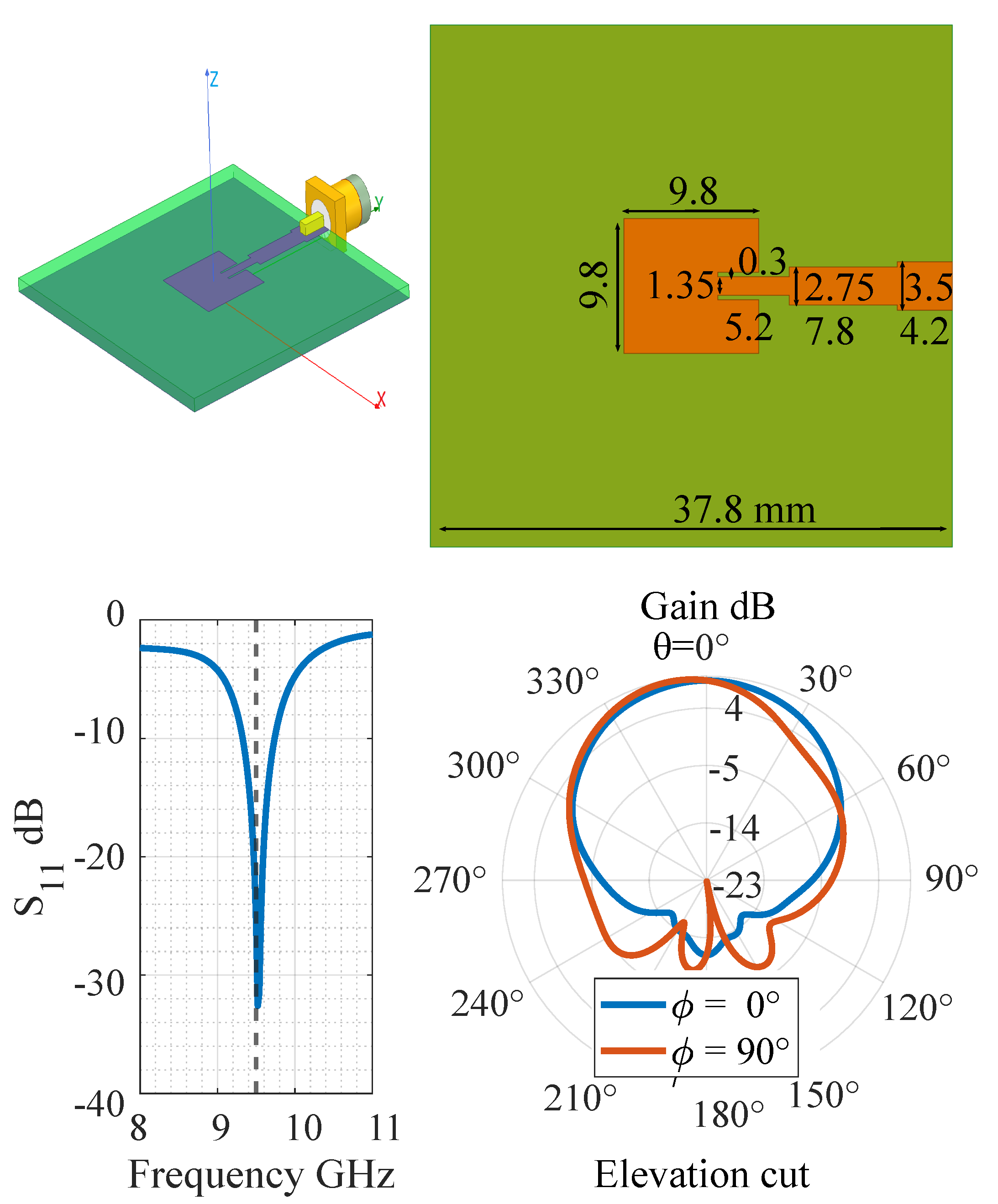
Figure 1). The antennas used in this research were rectangular inset-fed patch antennas with a 9 dBi gain, resonating at 9.5 GHz. They were fabricated on a grounded RT Duroid 5870 substrate with a height of 1.57 mm. The dimensions of the patch antenna, as well as the simulated reflection and elevation cuts of its radiation pattern at azimuthal angles
and
, are shown in
Figure 2. In the polar plot,
represents the polar angles measured with respect to the z-axis.
The primary objective was to improve the isolation level by about 20 dB, with respect to the reference without absorbers or MMs, across the entire operational frequency bandwidth of the FMCW radar, spanning from 9.3 GHz to 9.8 GHz. All the metasurfaces have been designed using a full-wave RF solver, HFSS (High-Frequency Structure Simulator) [
23]. The ClearSpace FMCW radar systems use directional antennas with a much higher gain of the order of 20 dBi and a lower level of lateral radiation compared to the patch antennas. So, the worst-case scenario was studied in this research.
2.1. Compact EBG Design
EBG structures are usually designed to provide a bandgap within a designated frequency range, effectively reducing the surface wave propagation of both TM and TE modes. As is mentioned, such a design is particularly advantageous in scenarios where antennas and metasurfaces are integrated on the same substrate, like MIMO or phased array antennas.
In our case, as antennas are situated above a metallic plate, the designed EBG must engage with space waves in addition to the surface wave, to maximize the isolation. Hence, the EBG structure needs to be designed to interact with space waves in the fast-wave leaky TE mode region [
22].
A multi-objective genetic algorithm (MOGA) was applied to enhance the isolation capability of the EBG structure. The algorithm was implemented in MATLAB and integrated with HFSS [
23] for electromagnetic simulations. The optimization process started with a randomly generated population, where each individual represented a candidate design for the EBG unit cell. The optimization targeted two key objectives: (1) attenuating slow-wave propagation along the metallic interface and (2) supporting radiative TE-waves within the frequency range of 9.3–9.8 GHz. These objectives were evaluated using the dispersion diagram obtained from eigenvalue simulations in HFSS. The theory behind the dispersion diagram and the methodology for analyzing its results are explained in the following paragraphs. The MOGA employed tournament selection with 20% of the population chosen for reproduction in each generation. Genetic operators, such as crossover and mutation, were used to explore the design space effectively. The optimization iterated over multiple generations until the algorithm converged, meeting the predefined fitness criteria for both objectives.
The efficiency of EBG in achieving these goals has been studied by analyzing the dispersion diagram. The dispersion diagram illustrates how surface waves propagate through infinite 2D periodic EBG structures, identifying the frequency ranges where wave propagation is permitted or prohibited. An eigenmode full-wave EM solver was utilized to extract the dispersion diagram. The periodic boundary condition was applied to the unit cell borders. All four branches in the patch are identical and have rotational symmetry with respect to the center of the cell.
The dispersion diagram of the optimized EBG are shown in
Figure 3. In the dispersion curve, the supported frequencies are calculated as a function of wave-number
k along the symmetry points in the reciprocal space, called the Brillouin zone. For a unit cell with rotational symmetry, it is enough to calculate the
inside the smaller triangular area known as the irreducible Brillouin zone (
Figure 3). The dispersion curve is calculated along the line connecting these high-symmetry points. For a square lattice with the length of
a, the symmetry points are marked with
(
k = (0,0)),
(
k = (
,0)), and
(
k = (
,
)) [
24].
The TM band starts at DC (
) and consistently remains within the slow-wave region, positioned below the light line, indicating bounded surface wave propagation. In contrast, in the
-
direction, the TE band starts in the fast-wave region, highlighted in green in
Figure 3. The supported wave in this region has the phase velocity
higher than the speed of light. These waves are referred to as TE leaky modes because they possess radiative characteristics and can couple with space waves [
22,
25]. So, in the frequency ranges of 9.3 to 9.8 GHz, the EBG structure can interact with lateral waves and re-radiate them as space waves perpendicular to the EBG plane.
As the wave vector k increases, the dispersion curve intersects the light line and continues with a phase velocity lower than the speed of light. In the slow-wave region, a bandgap is created, which means the slow-wave propagation in the entire FMCW operational bandwidth is not supported, and slow waves are attenuated. The same argument applies to the third path, i.e., the - direction.
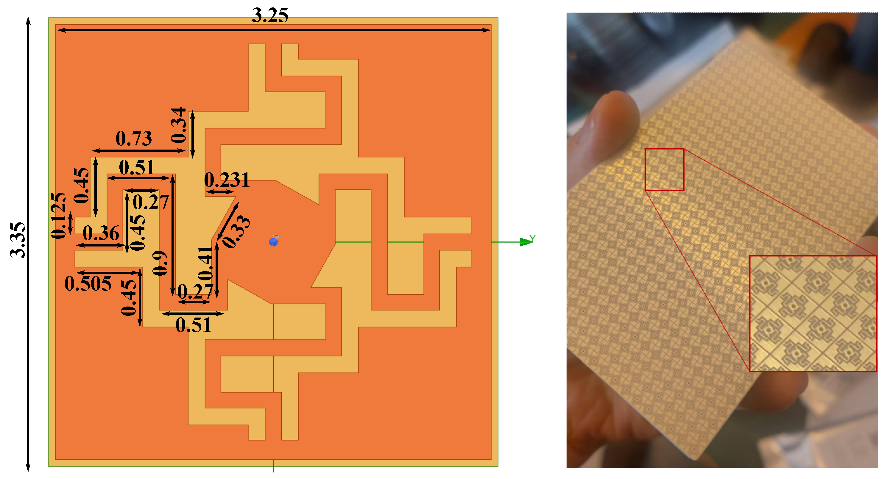
The dimensions of the designed EBG unit cell and the fabricated panel are illustrated in
Figure 4. The unit cell is compact with dimensions of 3.35 mm × 3.35 mm. The EBG panel was fabricated on a 0.508 mm Roger 4350 substrate.
2.2. Broadband Textured HIS Design
HIS surfaces are a periodic arrangement of resonant elements designed to control surface wave propagation in a specific and predefined manner. These surfaces are created by texturing the interface between two media, by implementing an infinite array of 2D printed circuit elements including frequency-selective surfaces (FSSs) [
26,
27,
28]. HIS surfaces are engineered to achieve specific impedance characteristics at a certain range of frequencies. When an incident wave approaches the HIS surface, it induces surface currents and electric charges on the interface so that the incident wave reflects in a specific spatial direction. In our research, the design of HIS aims to redirect the space waves far away from the receiver antenna.
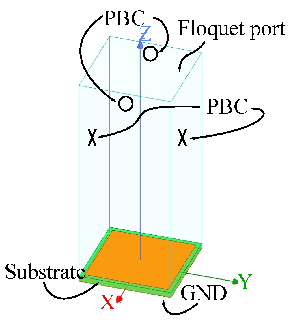
In the design of the unit HIS cell, an infinite 2D periodic array of square patches on a grounded Roger 4350 substrate was first considered. A 3D full-wave EM model of a single cell was employed to extract the impedance of the HIS unit cell (
Figure 5). The Floquet boundary condition was applied. Perfect Electric Conductors (PEC) were assigned to all metallic elements, and the thickness of the substrate was 0.508 mm. The impedance of HIS surface
, can be extracted directly with
Here,
and
represent the average
x component of the electric and
y component of the magnetic fields at the interface [
29,
30,
31]. The variation in
as a function of gap sizes at four different frequencies is plotted in
Figure 6. In all cases, the cell length is kept unchanged at 8.33 mm.
To overcome the narrow bandwidth characteristic of a uniform gap length HIS, an array of non-uniform patches with varying gap lengths was designed. From
Figure 6, it can be observed that the peak of
shifts toward a larger gap length as the frequency increases. This implies the possibility of covering a wider frequency range with a varying gap length structure.
The design and optimization of the non-uniform HIS surface focuses on achieving minimum radiated power in a lateral direction using a 4 × 2 array of HIS macro-cells within the frequency range of 9.3 to 9.8 GHz (
Figure 7). Each macro-cell has a two-fold symmetry around axes AA’ and BB’ (
Figure 7: zoomed-in panel). A genetic algorithm optimization method was employed to minimize the elevation plan’s far-field radiation of a patch antenna (YZ plane). The antenna is located 65 mm away from the non-uniform HIS panel shown in
Figure 7. The ground layer is a PEC. The dimensions of the macro-cell and gap distances between the
th and
th patches,
, are listed in
Table 1.
The radiated far-field gain at different frequencies in the
plane is shown in
Figure 8. As depicted in the figure, a minimum isolation of about 14 dB was achieved using a 2 × 4 macro-cell panel for all frequencies higher than 9.4 GHz. A photo of the fabricated HIS panel, which contains 4 × 6 macro-cells, is shown in
Figure 9.
3. Experimental Validation of HIS and EBG Structures
The efficiency of designed MMs in suppressing the mutual coupling of Tx/Rx patch antennas on a metallic ground plane was measured (
Figure 10). As is mentioned, two identical patch antennas with the center resonance frequency of 9.5 GHz were located on opposing ends of a rectangular aluminum ground plate. Both antennas were mounted 16 mm above the metallic plate, and the distance between the two antennas was set to 800 mm.
The coupling between two antennas
was measured in an anechoic chamber for different cases: with EBG blocks at the center, with an HIS sheet, and with an absorber sheet (
Figure 10). The absorber sheet used in this measurement was Laird Eccosorb HR-10 with a frequency range between 5 and 90 GHz. The measured results are plotted in
Figure 11 and compared with the reference measurement, which was taken without any absorber between the two antennas. The measurement results indicate that the designed EBG surface has a wider absorbing frequency range compared to HIS. A single HIS panel suppresses leakage starting from 9.4 GHz, and the EBG surface dissipates incident power from around 9.1 GHz. At higher frequencies up to 9.8 GHz, both HIS and EBG sheets reduce the coupling by about 10 dB as the absorber sheet does.
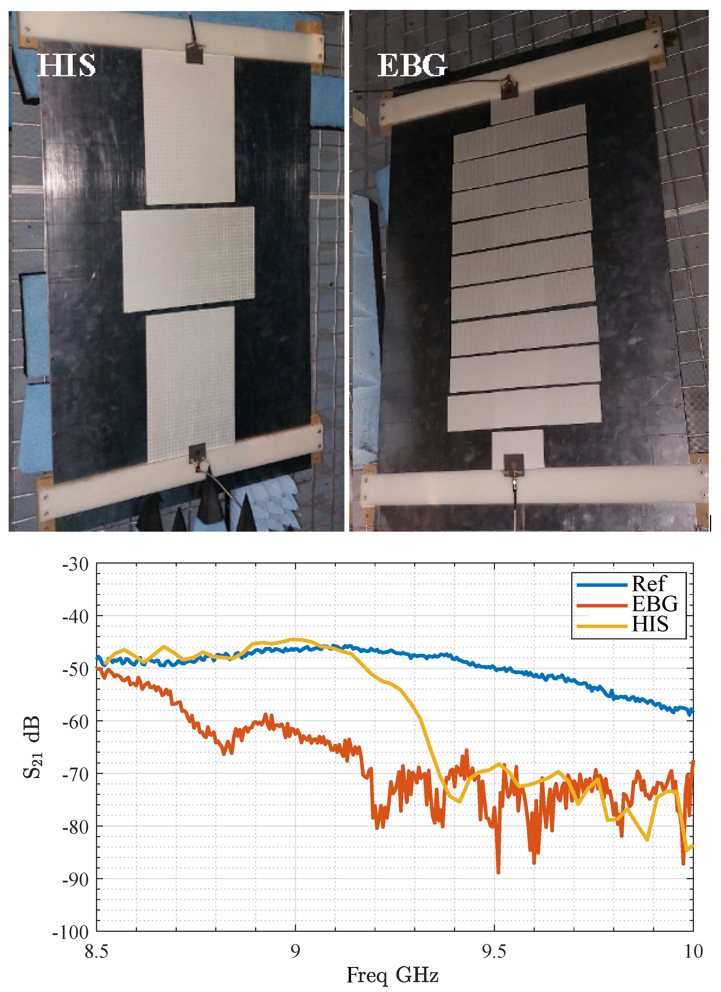
The coupling reduction between two antennas is measured when a larger area between the antennas is covered with MMs, as shown in
Figure 12. The total coupling reduction for both cases is plotted in the same figure. HIS sheets dissipate surface waves at frequencies above 9.2 GHz. At 9.3 GHz, the isolation improves by approximately 10 dB, reaching 20 dB in the frequency range of 9.4–9.8 GHz. The EBG layers start operating at 8.5 GHz, providing an average isolation improvement of -20 dB between 9.1 and 9.8 GHz. At higher frequencies, the decoupling improvement remains significant, achieving about 10 dB at 10 GHz.


