Abstract
Robots are becoming an integral part of space facilities construction and maintenance, and may need to move to and from different work locations. Robotic arms that are widely employed, which are mounted on fixed bases, have difficulty coping with increasingly complex missions. The challenge discussed in this paper is the problem of the efficient locomotion of robotic systems. Inspired by the gliding motion of a flying snake launched from a tree and combined with the weightlessness of the space environment, we design similar motions for the robot, including the following three steps. First, the robot folds its body like a snake and initiates flight by accelerating the global center of mass (CM), focusing on the movement direction and generating suitable momentum. Then, during the flight (free-floating) phase, the joint motions are planned using a nonlinear optimization technique, considering the nonholonomic constraints introduced by the momentum conservation and the system states at the initial and final states of the floating. Meanwhile, the difficulties caused by long-distance flights are addressed to reduce the motion computational cost and energy consumption by introducing the phase plane analysis method. Finally, the landing motion is designed to avoid rigid collisions and rollover on the radial plane. The numerical simulations illustrate that the three phases of maneuvers are smooth and continuous, which can help the space robots efficiently traverse the environment.
1. Introduction
In the future, large-scale space facilities such as solar power stations and in-orbit laboratories will be constructed [1]. Different sites will be characterized by distant venues, and this requires a higher level of autonomy and flexibility [2]. Furthermore, in complex unstructured environments, the distance between two locations may be so remote and rugged that they cannot be moved by mechanical locomotion. In nature, different animals have various ways to move, such as gaiting, rolling, and flying. Of these different forms of movement, flying has been shown to be the least costly in terms of energy consumption and is better adapted to the environment [3,4]. In the low-gravity environment, long-distance flights usually rely on wings or propeller-like structures. However, leaping gaits in weightless environments can result in extended phases of flight, offering intriguing new perspectives for studying efficient travel. For example, robots work on large space structures and move efficiently between different facilities using jump-started flights, as shown in Figure 1. This work focuses on the topic of efficiently controlled weightless locomotion with chain-type robots and the challenging problems that must be solved, including robot jumping, a floating attitude, and landing control.
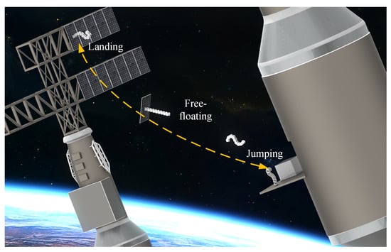
Figure 1.
Chain-type robots initiate flight through gait and adjust attitude during the free-floating phase to land softly.
In Earth-like gravity conditions, there are many solutions for robotic motion, and related research is well established [5,6]. In low-gravity environments, researchers have carried out in-depth studies on the mobility of space robots, mainly focusing on planetary exploration. Examples include legged robots for advanced mobility through jumping and chain-type robots with excellent passability [7]. Despite the significantly different gravity of the two scenarios, both need to overcome at least the force of gravity or friction to move. Applications in weightless environments present a fundamentally different problem. A current standard method is a free-flying system with integrated thrusters, but such additions are complex and require additional controls. An example is the Astrobee robot that uses propulsion modules to move inside the space station [8]. The module includes a centrifugal fan for generating an airflow and nozzles in different directions. The robot’s load includes sensors, microphone arrays, and a small perching arm. This quadrotor-like system can only work inside the cabin. In another case, closer to the target application of this paper, the attached assembly robot can move over the surface of the spacecraft, resulting in an extended working area [9]. Typical examples include the Skyworker [10,11], a three-branch robot using gripper jaws to travel on the truss, and the Canadarm, which can move across the surface of the International Space Station (ISS) using the standard interfaces [12]. However, gait motion requires the frequent acceleration and deceleration of the system, which consumes much energy to overcome inertial forces and creates shock for the joints. Maintaining the space system in uniform linear motion can avoid the above problems. In the weightless environment, giving the system an initial momentum allows for long periods of floating movement with little energy consumption.
Research on snake robots has consistently been a popular field, with most studies focusing on structural design [13] and biomimetic movement [14,15,16]. The latter primarily involves imitating the rhythmic motion of snakes to navigate terrestrial environments [17]. However, it seems that few researchers have connected the movement and flight of snakes. We observed an interesting phenomenon in nature: flying snakes glide efficiently through complex environments. In some demonstrations, the visual and intuitive steps can be divided into three parts (as shown in Figure 2). First, fixing the body with the tail wrapped around a branch and compressing the first half of the body configuration. Then, stretching the body so that the global CM generates a large velocity and releases the tail to initiate flight. Finally, swinging the body to adjust the landing attitude in the flight phase [18]. Similarly, astronauts can fly close to the predetermined location by imparting reaction forces to the space station based on their experiences [19,20]. Inspired by these observations, we introduce the motion of a flying snake into the design reference of the controller and propose a new control strategy for the movement of the space system: accelerating the global CM from the base to initiate the flight, and using internal movement adjustment system configurations to achieve a soft landing in the free-floating phase. To the best of the authors’ knowledge, no similar investigation has been conducted before.

Figure 2.
The flying snake travels through complex jungle environments. Images courtesy of Discovery UK.
Another related problem that arises from this is the control of the free-floating space robots (FFSRs). The effect of any angular momentum generated during takeoff on the system is amplified over time, producing significant attitude changes. The posture during landing needs to be controlled to mitigate the impact on robots [21,22]. A typical example is that a free-falling cat with an arbitrary attitude can achieve a quadrupedal landing to avoid injury by using the movements of its spine [23,24]. This phenomenon is a consequence of the law of constant angular momentum. However, the conservation of momentum brings about nonholonomic constraint equations whose nonintegrable properties are detailed in the literature [25,26]. FFSRs are inherently hyper-redundant and underactuated, and the attitude cannot be directly controlled. This is also consistent with the high dynamic coupling between its internal structures [27]. It is convenient to control the attitude of a space system using reaction wheels [28]. However, it requires adding dedicated accessories, which is unsuitable for agile systems. We use another approach, similar to the movement of animals in mid-air, achieving a soft landing through internal movements only. Many investigations have considered only the case of zero initial angular momentum [29,30]. These assumptions can be mathematically convenient, but have limitations. A few researchers have analyzed systems with nonzero angular momentum and proposed some joint-space path planning methods [31,32]. However, the focus is still on gravity environments with short robot lag times. Moreover, the system’s initial linear and angular momentum is given in these studies without considering how the system reaches a particular dynamic state. None of these methods address the complexity and challenges arising from the mobility strategy proposed in this paper.
In summary, the main contributions of this paper are as follows. First, we propose a new approach for the mobility of space systems, utilizing free-floating states to traverse complex environments and reach distant locales. Then, we give the mathematical models of the system in different steps, focusing on analyzing the intrinsic constraints between different models. Finally, a phase plane-based motion planning is proposed for long-range mobility, and this approach significantly reduces the robot’s computational cost and energy consumption. We illustrate specific computational methods for the joint motion planning of the system transitioning from the initial position to the target through examples. It is also important to note that the work in this paper focuses on a more general serial robot model, and the proposed method can be easily replicated for similar robotic systems as long as they can be reduced to a three-link model with two rotary actuators.
The remainder of this paper is organized as follows. Section 2 discusses how the space system can efficiently move through jumping motions. Section 3 derives the proposed mathematical model and boundary conditions. Section 4 details the computation of the joint trajectories at each phase. Then, the effectiveness of the method is analyzed in Section 5 through two scenarios. Finally, Section 6 concludes this article.
2. Highly Efficient Mobility Strategy
This paper focuses on planning the motion of chain-type systems in a 2D space, including changes in the position and orientation. In order to achieve this goal simply and generically, we have taken a chain-type robot that controls two rotary actuators. The fixed-configuration robot or reconfigurable robot model can be pictured as a simplified three-links robot, as shown in Figure 3a. A scenario is shown in Figure 3b, and the strategy proposed to mimic the flying snake movement can be decomposed into four steps:
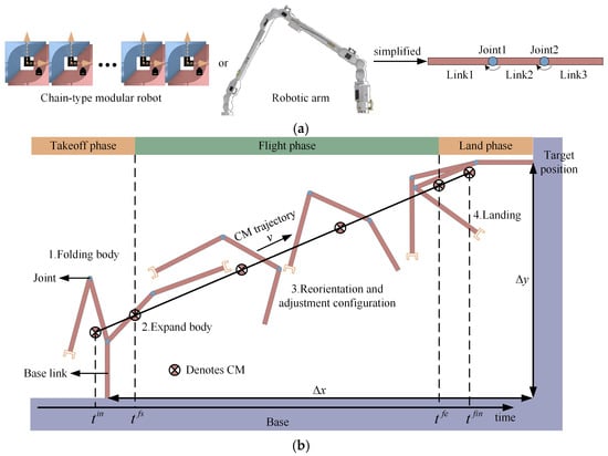
Figure 3.
(a) Geometric modeling of the chain-typed robot; (b) the steps of decomposition of jumping locomotion.
Step 1. The CM trajectory is obtained from the start and target positions of the base link, and the starting and landing configurations of the robot are also determined.
Step 2. The range of the initial angular momentum is estimated from the net rotation of the base link, and the intrinsic dynamics of the system are analyzed to derive the momentum constraints to compute the joint space trajectories.
Step 3. During the free-floating process, a path is found in the joint space that can transfer an initial configuration to a desired final one. The space system needs to reorient itself from any orientation to put the base link in a suitable landing orientation.
Step 4. The joint coordination achieves a smooth and gentle landing.
Based on the constraint characteristics, the dynamic modeling of the system can be divided into the stance (jumping and landing) phases and the flying (free-floating) phase. The former is a fixed-base system with holonomic constraints, and the latter is a free-floating system with a nonholonomic constraint on the conservation of momentum. The principle of the proposed migration method is that the momentum of the FFSR is always constant. On the one hand, the linear momentum is constant, which means that the robot cannot interfere with its floating direction once it leaves the base, and the CM always remains in a uniform linear motion. Concretely, this allows space systems to undergo a distance without the need for a specialized road. On the other hand, the system angular momentum is constant, and even if the joints do not turn, the robot may rotate around the global CM, causing a change in the direction of each link. This requires changing the moment of the inertia distribution of the system between the actuation of the joints for free-floating durations to controllable landing attitudes.
For the sake of uniformity and simplicity, we define some subscripts, including moments and phases. The subscript in (initial) indicates the beginning of the movement, fs (free-floating start) indicates leaving the base, fe (free-floating end) indicates touchdown, and fin (final) indicates the end of the movement.
3. Dynamic Modeling of Robotic System
The inherent underactuation of the FFSRs has been discussed above. On the other hand, we can control the two actuated DOFs during the jump phase, but need to affect the behavior of the three DOFs, including the angular momentum and the vector linear momentum . This means that each step of the movement brings about the coupling of dynamical parameters, which affects the future state of the system. New approaches are needed to tackle these challenges. Therefore, we need to analyze the mathematical model in detail and plan each joint position carefully to achieve efficient and accurate movement. In order to provide a better explanation of the constraints and principles, the relevant notations and formulas are derived in this section.
3.1. CM Kinematics
The serial robot can be simplified into the rigid body links articulated, as shown in Figure 4a. The kinematic chain starts at link 0 (base) and has a total with links and j () revolute joints; the origin of the inertial reference frame is at the base. The joint angles between the link i () and the horizontal is , and the angle between the link i and the link is . The counterclockwise direction is positive. The action space is defined in the generalized coordinates and , with . Both provide a complete description of the state of the system with the fixed-base robot. For a free-floating system, as shown in Figure 4b, it is necessary to add (the orientation of the base-link) for to completely describe the orientation of each link, defined as . In a fixed-base robot, stand for the global CM coordinates, and the position vector of the is . In a free-floating robot, the origin of the coordinate system is located at the global CM, and the position vectors of the can be denoted by . The vector connects joint i to , and the vector connects to joint . , , and are the mass, length, and inertia moment of the link i, respectively.

Figure 4.
Simplified geometric model of the system: (a) articulated robot model with fixed base; (b) geometric model of the free-floating robot.
In a fixed-base system, the parameter vectors of the links are combined to yield the position, which is given by
Similar to the vector , the global CM can be expressed as
where is the total mass of the system. And its velocity and acceleration are given by
where is the CM Jacobian matrix. In addition, we propose the concept of a CM reachable space similar to the robotic arm reachable workspace for describing the area that the CM can reach. Equation (3) needs to be converted to a state-space model (SSM) for computation and analysis. Defining the state variable by to describe the system, we can derive a state-space representation of the motion of the CM, which yields
where and can be derived from Equations (2) and (3), and is the input variable, which is the acceleration of the global CM.
3.2. Dynamic Modeling of the System
Due to previous theoretical work in this area, we can keep the content concise and focus on unique efforts. The position of the CM moves with the system during free-floating. It is appropriate to establish a reference frame at the global CM to describe the dynamic behavior of the system, as shown in Figure 4b. We use the well-known Lagrange method to describe the variable constraint dynamics model. The kinetic energy T in a weightless environment is the total energy of the system, as
For an FFSR with initial angular momentum h, the equation of the motion is given by [33]
where is a positive definite matrix, depending on the mass, the geometrical parameters, and the configuration of the robot, and the matrix contains the nonlinear Coriolis and centrifugal terms, while the vector is a term related to the angular momentum. The column vector represents the torque corresponding to the generalized coordinates. It is worth mentioning that the model can be used to analyze the dynamic behavior of a fixed-base robot when the mass and inertia of the base-link are much larger than the rest of the links ().
3.3. Momentum Analysis
The free-floating robot falls under the category of momentum conservation, and its floating direction and initial angular momentum are determined by the take-off process, which is necessary to analyze. Firstly, according to the theory of a multi-rigid body system, the linear momentum of the fixed-base robot can be expressed as
If the initial linear momentum is given, the position of the CM can be easily obtained by integrating Equation (7). On the other hand, the attitude of the system cannot be calculated directly and is related to the initial angular momentum and joint trajectories. The total angular momentum of a fixed-base robot includes the angular momentum resulting from global CM movement and the angular momentum of the link i with respect to the CM, which is given by
where denotes the total angular momentum with respect to the global CM, which is also the total angular momentum of the FFSR. Since there is no external force, the conservation of the angular momentum can lead to
After some algebraic manipulations of Equations (6) and (8), the angular momentum can be described as [34]
where is the function related to the inertia parameter of the links and the joint angle . The rotational velocity of the base link relative to the reference is obtained according to Equation (10)
The orientation of the system during free-floating is related to the actuation of the joints. If the joint angles as a function of time and the initial state of the spatial system are known, it is possible to calculate the orientation of the robot at each moment. The orientation of the base can be obtained by integrating Equation (11)
where is the initial orientation of the base link. It can be observed that both the initial linear and angular momentum are related to the joint angle and velocity.
3.4. Constraint in Motion Planning
The effect of the initial angular momentum on robot orientation has been investigated [35]. As an adaptation of the previous conclusions, we further consider the possibility that the robot may experience more than one turn during the extended flight phase. The net rotation of the base in the initial and final states is specified, but the base cumulatively undergoes an angle that may be different from , as , where m is the number of turns. The interval of is related to the initial angular momentum and flight time. The coupling between them is crucial and is the subject of the next section. Integrating Equation (10) yields the following results
where is the free-floating time duration, related to the linear momentum and the distance traversed. We use internal movements to control the orientation of multibody systems; a relevant example is that skaters rotate faster when they hold their arms up than when they open them, but this is not arbitrary. The functions are bounded, and the upper and lower bounds of the terms in Equation (13) can be estimated as
where the deviation is given by the final and initial joint angles, which is related to movement planning. Summing the corresponding terms of Equation (14) as the interval of the initial angular momentum
The coupling between joint movements and the attitude of the FFSR is highly nonlinear and complex. The method given above for the boundary evaluation of the initial angular momentum considers the upper and lower bounds of the parameters. It can be used as a reference for planning. However, the results should not be interpreted as a claim on the accuracy of the angular momentum boundary. The mobility strategy proposed in this paper contains three steps. In order to make the joint trajectories smooth and continuous, each joint during the free-floating phase needs to satisfy six constraints, including the initial and final values of the angle, velocity, and acceleration. Based on the motion sequence defined in Figure 3b, the constraint equations are as follows:
4. Motion Planning
4.1. Prepare Configuration
Just as the flying snake needs to fold its body before gliding and adjust its orientation before landing, the chain-type robot also needs to adjust its joint angles to put the system in a suitable configuration before jumping and landing. This includes analyzing the floating direction and the stability of the stance phase. Given the base position, it is easy to derive the reachable space of the CM. However, this does not contain stability information and still needs to be combined with a stability criterion to plan the motion. Figure 5 illustrates that connecting the initial and target bases will intersect the CM reachable space (including regions a and b). We choose the configuration corresponding to the CM at point A as the prepared configuration, and for the three-link system, the CM position corresponds to a unique system configuration. The CM moves in a linear direction from A to B during takeoff, then the moments of the combined force acting on the robot around the axes x and y of the fulcrum point are zero, and capsizing around the fulcrum does not occur. This means that the maneuvers satisfy the zero moment point (ZMP) stability constraint [36]. Similarly, the configuration corresponding to the CM at point C is used as a target configuration before landing to avoid rigid collisions and the possible capsizing of the space system. The linear motion of the CM leads to .
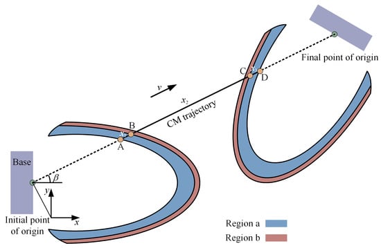
Figure 5.
CM reachable space and trajectory.
It is worth emphasizing that articulated robots with fixed bases have a singularity problem similar to that of robotic arms. The dynamics analysis may create torques that are difficult to execute when the joint is moving near the region where the singularities occur. The actual movement of the CM should avoid the region where the dynamic singularities may occur, as shown in region b in Figure 5, which affects the position of point C. However, the path of the FFSR is planned in the joint space, which is always feasible in the workspace and will not be affected by dynamic singularity problems. Finally, , , and in Figure 5 indicate the displacements of the CM in the takeoff phase, the free-floating phase, and the touchdown phase, respectively.
4.2. Joint Space Paths and Parameterization of Jumping
One assumption during the takeoff phase is that the manipulator’s base remains fixed. This premise is justified when the robotic arm is attached to a substantial track structure, as the mass and inertia of the track system exceed those of the robotic arm by more than two orders of magnitude [37]. Terrestrial robots, having a limited hang time, seldom focus on the precise control of momentum. The CM of the FFSRs moves in a uniformly linear manner and cannot actively regulate its orientation like a terrestrial robot can. We plan the joint paths considering the takeoff direction and eigenquantities (linear and angular momentum) as predefined objectives.
In the 2D scenarios discussed in this paper, controlling the position of the CM requires at least two rotary actuators. We aim for the proposed method to be suitable for common robotic arms rather than specifically designed robots. Robotic arms used in space applications typically have a shoulder–elbow–wrist serial structure with two parallel rotational degrees of freedom [38]. To reduce the computational complexity, this paper illustrates the proposed motion planning method using a three-link system as an example. The set of variables describing the time domain behavior of the system is defined according to Equation (4)
where and . When the direction of flight is determined (e.g., the angle with the horizontal is , as shown in Figure 5) and the initial joint velocities are zero, the CM movement needs to satisfy
Substituting Equations (3) and (18) into Equation (17) reveals the relationship between the joint motion and the motion of the CM, as
where , , and are functions of , and denotes the velocity of the global CM. It is worth mentioning that the joint space paths described in Equation (19) are characterized by their time independence. Therefore, we can initially compute the representation of these paths in the joint space. The trajectories can be easily parameterized to comply with the system’s hardware limitations. To compute the trajectories in the joint space, it is also necessary to determine the robot’s joint angles as it departs from the base, which is associated with the angular momentum boundaries. Substituting Equation (19) into Equation (10) and considering for the fixed-base system, the simplification yields the angular momentum h, which is given by
Appendix A provides the elements of the matrix . The flight time is related to both the distance and linear momentum, which in turn define the boundaries as given by Equation (13). So, is given by
When the target position of the robot is given, the displacement of the CM is also defined. Furthermore, during the free-floating phase, the displacement of the CM is significantly greater than the displacement during the acceleration and deceleration phases, (), which can be simplified by . Equations (20) and (21) are substituted into Equations (13) and (15) to convert the initial angular momentum interval to the joint angle boundaries for initiating the flight, yielding
It is observed that the initial angular momentum is independent of the joint velocity at takeoff, being solely related to the joint angle. If is small, the joint must complete the trajectory within a very brief period, potentially requiring unrealistic actuation. Equation (22) serves as a reference for these trajectories. When the CM acceleration decreases to zero, the robot can detach from the base to begin flight. The sine function is utilized to parameterize the CM trajectory, facilitating the derivation of continuous joint motions.
4.3. Free-Floating Nonholonomic Planning
The challenge during free-floating involves identifying a joint space path that transitions the space system from a configuration distant from the base to the landing configuration. Additionally, the maneuvers must ensure reorientation so that the base link achieves a suitable orientation for landing. The impact of each joint’s rotation extends beyond the end effector, affecting all other degrees of freedom (DOFs), including the orientation of the base link.
4.3.1. Short Flight
Arbitrarily rotating joints facilitate convenient calculations, but are not always feasible. The trajectory of each joint angle, combining a sine function with a polynomial, ensures that the rotation range remains within set boundaries. The presence of nonzero initial angular momentum introduces a time dependency in the joint movements. Therefore, the trajectory equation takes the form
where denotes the polynomial order with respect to the number of system constraints and are the polynomial coefficients to be solved. Moreover, defining the amplitude means that the polynomial coefficients in Equation (23) do not influence the joint boundaries. Section 3.3 and Section 3.4 outline the constraints for the joint trajectories, which include six boundary conditions for each joint and changes in the base attitude, as specified in Equations (12) and (16).
The angular momentum conservation equations for free-floating systems, which are highly nonlinear and coupled by coefficients, make the direct integration of Equation (12) impossible. We address these constraints using a nonlinear optimization approach, widely applied in nonlinear dynamics solutions and complex motion control planning. The algorithm employs the Sequential Quadratic Programming (SQP) method, calculating a quasi-Newton approximation of the Hessian matrix during its iterations. The SQP method consistently satisfies the bounds throughout all iterations. This strategy allows for a wide range of solutions, enabling the generation of joint trajectories that flexibly meet all constraints. Consequently, this method can yield an infinite number of joint angles. Ideally, we aim for shorter joint paths within a given timeframe, leading to reduced joint velocities and accelerations during movement. A rotation of more than 180° in one turn can be converted to a smaller rotation in the opposite direction. On the other hand, shorter paths can be generated by defining optimization criteria [39]. Nontrivial results can be found in the literature as
where is the 2-Norm. Optimization techniques permit the adaptable inclusion of constraints, such as the peak joint velocity and acceleration, followed by the introduction of variables to the trajectories. However, this is not the focus of the paper.
4.3.2. Long Flight
Long flight distances result in extended flight times, which, when combined with nonlinear optimization methods, introduce two significant issues. Firstly, the computational cost increases substantially, becoming unacceptable for onboard computers. Secondly, some joint movements are unnecessary and waste energy. Given the constant angular momentum of a free-floating space system, a system with constant joint configurations can be considered a rigid body rotating at a constant speed around a fixed axis. Equation (11) degenerates into
To obtain a more intuitive illustration, we discuss three cases by analyzing the value of the angular momentum h, as shown in Figure 6.
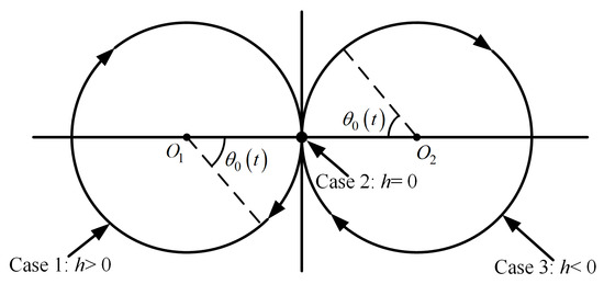
Figure 6.
Phase plane illustration.
Case 1: . The orientation of the underactuated system base moves clockwise along the circle in the phase plane with a constant angular velocity .
Case 2: . In this case, is obtained from Equation (25), which indicates that the space system has no rotation around the CM.
Case 3: . The underactuated DOF undergoes a movement similar to that in Case 1, but in the opposite direction, corresponding to the circle in Figure 6.
Dividing the long flight duration into three phases offers a natural solution. First, the robot joints are converted from dynamic to static. Then, the configuration is maintained for flight. Finally, the configuration is changed to meet the landing requirements, as shown in Figure 7. Points A and B correspond to , , and , where the angular velocity of the system is minimized. To accomplish the trajectory development, some analyses have been carried out (with ). First, we calculate the orientation of the base link at the end of the transition stage, represented by in Figure 7. We are not concerned with the exact shapes of the phase portraits (base angle) during the transition stage. The duration of the transition stage is fully known. After the transition stage, the joint velocities become 0, and the system angular velocity becomes constant. For a free-floating system reorientation, a net rotation of 180° is the worst-case scenario. The time () taken for a half-turn can be estimated by Equation (13), which can be used as a reference for the duration of . The state in both stages ( and ) are represented by dashed lines in the phase plane, as shown in Figure 7. The motions corresponding to and are solved by nonlinear optimization. Finally, the duration of the constant angular velocity rotation of the system corresponding to the circular arc can be easily calculated. Note that point A moving through the circular arc to point B may undergo multiple turns. The is given by Equation (21).
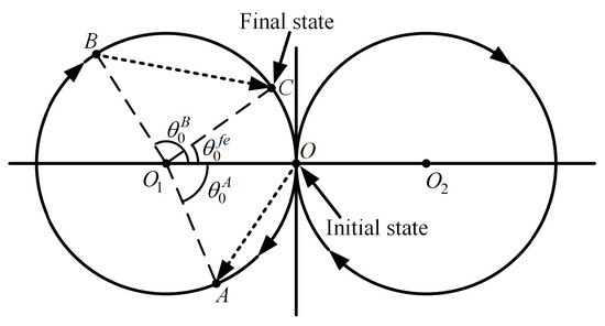
Figure 7.
Phase plane illustration.
Short-distance movements can be regarded as a special case of long distances, i.e., the state of the system transitions directly from point O to point C. The system for a long-duration flight has enough time to adjust its attitude and configuration, so the range of feasible takeoff configurations is large.
4.4. Soft Landing
The goal of the landing stage is to return the robot to a stationary state as swiftly as possible and land softly without bouncing. This is an essential feature of the proposed method: the robot system starts and stops smoothly from zero velocity and zero acceleration. The takeoff movements determine the velocity of the CM, as
where and represent the CM acceleration during the takeoff and landing phases, respectively. Similarly, trigonometric functions can be used to parameterize the acceleration of the CM. Ground reaction forces impact terrestrial jumping robots during the landing collision phase. The on-orbit environment is weightless, and only the inertial forces are to be considered for impact forces and tipping. Landing can be regarded as the reverse of the takeoff maneuver, but there is no need to take momentum into account. The configuration in which the robot ends up floating is related to the CM position, as shown in Figure 5. Finally, the velocity of the CM does not change abruptly, which can be used as boundaries to avoid rigid collisions.
5. Algorithm Verification
In this section, some numerical simulation results are included to verify the validity and efficiency of the proposed trajectory planning scheme from the kinematic viewpoint. The SSMs for the takeoff and landing phases can be easily solved as ordinary differential equations using the ODE45 method. Equation (24) is solved by means of nonlinear optimization. The implementation of these solvers was carried out in Python. All computing processes and simulations were performed on a personal computer with the main configuration consisting of the I7-10700 CPU (Intel, Inc., Santa Clara, CA, USA) and 16G of RAM (Micron, Inc., Boise, ID, USA). We use a three-link mechanism and set up two scenarios to validate our methods, including an example of a near move (Scenario 1) and a far move (Scenario 2). The parameters of the system are shown in Table 1. The in Equation (23) that limits the maximum joint rotation is 140°.

Table 1.
System parameters.
The position and orientation of the robot are defined according to the fixed coordinate system shown in Figure 4a. The detailed parameter settings of the target positions in the two scenarios are shown in Table 2.

Table 2.
Parameters of target positions.
5.1. Scenario 1: Short-Distance Movement
We present an interesting example of a robotic arm that moves to a specified position by jumping inside the cabin. The prepared configuration of the system is . The path in the joint space that satisfies the CM linear movement is shown in Figure 8a, which is independent of time. Smaller torques result in smaller takeoff speeds, and the space system may take longer to reach a specific target position. Equation (22) proves that the joint trajectories satisfying Figure 8a are all valid in the sense that the free-floating motion has a solution. The ratio of the linear and angular momenta is given in Figure 8b. Our method takes advantage of the fact that the linear and angular momenta do not follow the same trend with the joint rotation. satisfy Equation (22) and can be used as configurations for takeoff.
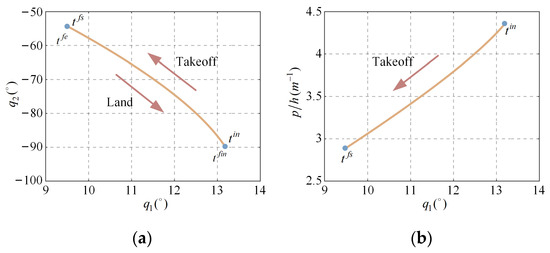
Figure 8.
Path in joint space of two articulated joints , : (a) during take-off phase; (b) vs. .
We use trigonometric functions to parameterize the CM trajectory, and the peak velocities and accelerations of each joint are extracted from solving the SSM Equation (17). The initial velocity of the CM is also given as and the initial angular momentum . Then, the paths in the joint space during the landing phase are computed according to the methods introduced in Section 4.4. The space system produces a net rotation of 180°, so the locomotion during the landing phase is a playback of the take-off. For practical reasons, the operation time is limited. Thus, parameterizing the trajectory requires considering whether joints have enough power to perform the maneuver in the allowed time. Table 3 lists the configuration variables for the joint at the start and end of the flight.

Table 3.
The system configuration.
The primary task of the space system during the flight phase is to adjust the attitude and joint configuration variables. In this scenario, the base requires a net rotation of 180°, and clockwise and counterclockwise rotations are equivalent. Nevertheless, the latter, as a constraint, yields a smaller maximum acceleration of the joint. On the other hand, to avoid generating unrealistic joint trajectories, it is necessary to constrain the parameters in Equation (23) during the optimization process, aiming to achieve the possible solutions. Figure 9a depicts snapshots of the robotic arm motion, while Figure 9b illustrates the orientation of the base. The velocity and acceleration of the CM are given in Figure 9c, and the system initiates flight when the CM acceleration is equal to 0. Figure 10 shows the joint trajectory, velocity, and acceleration. Segments a, b, and c represent the takeoff, flight, and landing movements, respectively.
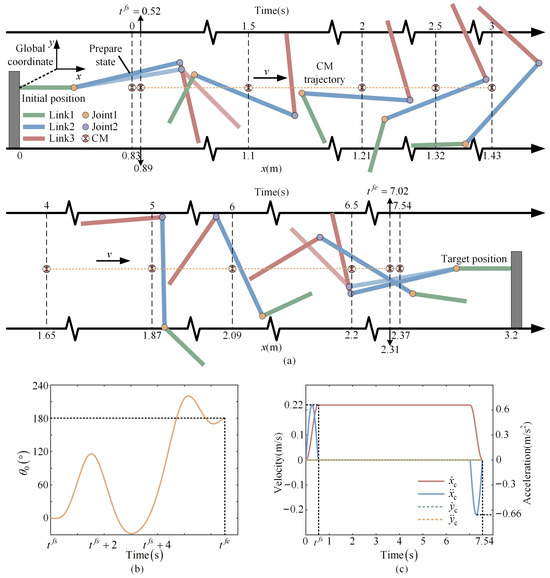
Figure 9.
(a) Snapshots of a robot moving; (b) the orientation of the base; and (c) the velocity and acceleration of the CM in both directions.

Figure 10.
Joints data of simulation Scenario 1.
5.2. Scenario 2: Long-Distance Movement
In this experiment, a robotic arm jumps from the ground of a large space facility to the wall diagonally above it. Compared to the previous scenario, this required traversing a much longer distance across the venue. The joint space paths for the takeoff and landing phases are shown in Figure 11, and the joint configuration variables at moments and are given in Table 4. The joint trajectories illustrated in Figure 11 can be made such that and . Parameterizing these trajectories yields an initial velocity and an initial angular momentum .
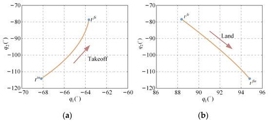
Figure 11.
Path in joint space of two articulated joints during takeoff (a) and landing phase (b).

Table 4.
The system configuration.
Next, we plan the two segments of joint movements in the long flight time according to the variation law of the phase portrait. First, the angle, angular velocity, and acceleration of the joint converge to 0. For this purpose, Equation (12) is integrated with respect to time to obtain . The system of straight chains has a minimum angular velocity with . Then, the joints deactivate for a period of time, and activate again before landing. Figure 12 shows snapshots of the robot motion. Figure 13 corresponds to the joint angle, velocity, and acceleration.
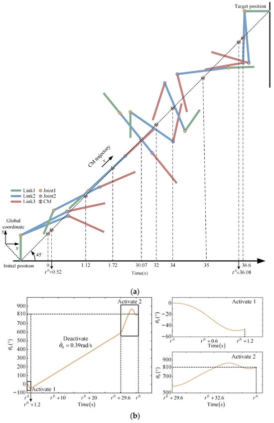
Figure 12.
(a) Snapshots of a robot moving to the target position. (b) The orientation of the base during free-floating.

Figure 13.
Joints data of simulation Scenario 2.
Figure 12b illustrates more than one cycle of rotation that the system may experience during free float but with a net rotation of 90°. Thus, the robot can achieve the target position correctly. Segments a and e in Figure 13 represent the joint motions during the takeoff and landing phases; segments b, c, and d correspond to phases , , and in Figure 7, respectively. Overall, these features are implemented without the reaction system, and the joint space paths are smooth and easy to follow. However, this result is unrealistic when considering the effects of a gravity environment.
5.3. Discussion
Currently, the collaborative arms inside the cabin are mostly immobilized, and the movement of the robotic arms outside the cabin relies on a large number of customized connecting surfaces, which limits the utilization of expensive launch payloads. It is difficult for robotic arms to tackle handling tasks for the on-orbit assembly of complex structures. In previous work, a robotic arm moves step-by-step, which is the standard method for moving the robotic system, but this approach depends on feasible paths. We propose a strategy of traversing long distances by flight that has good environmental adaptability. It is applicable in different scenarios, does not rely on structure-specific models, and can exploit the full potential of existing robots. Chain-type robots are common in space applications and are used for manipulation; famous examples include the Canadarm 2, the Chinese space station remote manipulator, and many more [40]. It is also worth emphasizing that flight is low-cost in terms of energy consumption because the robot avoids having to overcome inertial forces frequently, and the global CM experienced a single acceleration and deceleration throughout the entire motion. This advantage is more significant over long distances, as shown in Figure 14. Only a short activation is needed to adjust the system configuration during the long free-floating phase. It is noteworthy that a robotic arm can also transport loads using this method simply by considering the end-effector and the load as a unit. Achieving these requires the robot to have two rotary actuators. This type of robot is common in space applications.
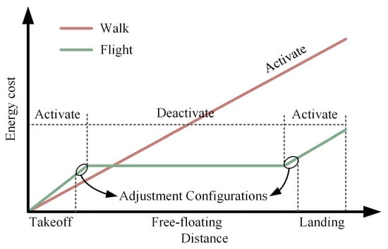
Figure 14.
Energy consumption in different movement modes.
On the other hand, the joint space paths are smooth, devoid of any abrupt changes or sharp turns, with transitions that are continuous. Another important feature of the proposed method is the smooth start and stop of the system at zero. We detail each step involved in the computation of controller parameters. Controlling space systems also necessitates a focus on computational costs. The time complexity for most nonlinear optimization problems can be addressed with polynomial time algorithms, determined by the number of DOFs [41]. The robotic system’s control during takeoff, free-floating, and smooth landing is achieved with only two rotary actuators, allowing for easy real-time implementation on an on-board computer. Regarding orientation control in the free-floating phase, our method simplifies the mechanical complexity and reduces the cost of the robot, unlike approaches that depend on reaction systems. Given hardware limitations, finding a feasible joint trajectory to transition the system from its initial to target location is not always possible, especially in scenarios like close-range movement or when the load inertia significantly exceeds the robot’s capacity, necessitating large baseline reorientations.
6. Conclusions
In general, extending the working area of robots and achieving efficient transportation is crucial for building space facilities. Most space robots used for manipulation lack integrated thrusters, making them susceptible to hindrances from environments or paths in distant locations that may not be accessible through mechanical movement alone. In this paper, we propose a jump-flight mobility strategy that efficiently traverses environments using only two joints, enabling precise jumping and landing. As of now, we have not encountered any similar solutions. This paper focuses on analyzing the feasibility of this movement method and the inherent constraints of linear and angular momentum during takeoff. First, the motion of the flying snake is proposed as a reference for the controller design, enabling the system to ‘fly’ to the target location. This method is more energy efficient and adaptable to the environment than traditional gait methods. It also avoids the frequent impacts of the acceleration and deceleration of joints. Then, we derive the dynamics and boundary constraints for fixed-base and free-floating space systems and give a detailed computation of the controller parameters. The simulations demonstrate that the results of the method are smooth and continuous. Finally, this paper validates the proposed approach using a general articulated robot, a type of serial robot that is common in space applications.
The motion strategy proposed in this paper relies on an accurate dynamic model, with the controller being open-loop. This means that even minor disturbances could cause the system’s state to diverge, leading to unexpected behavior. Ensuring that the designed controller can be reliably deployed on hardware to achieve the intended objectives will be the subject of future work.
Author Contributions
Conceptualization and investigation, Z.Y.; methodology, Z.Y. and S.Z.; funding acquisition, Y.Z. and J.F.; writing—original draft, Z.Y. and S.Z.; supervision, J.Z.; visualization, J.Q. and N.Z. (Ning Zhao); validation N.Z. (Nanlin Zhou). All authors have read and agreed to the published version of the manuscript.
Funding
This work was supported by the National Science Fund for Distinguished Young Scholars of China (Grant no. 52025054) and the National Natural Science Foundation of China (Grant no. U2013214).
Data Availability Statement
Data are contained within the article.
Conflicts of Interest
The authors declare no conflicts of interest.
Appendix A
References
- Moghaddam, B.M.; Chhabra, R. On the guidance, navigation and control of in-orbit space robotic missions: A survey and prospective vision. Acta Astronaut. 2021, 184, 70–100. [Google Scholar] [CrossRef]
- Sho, N.; Keiko, N.-M. GITAI USA: Providing safe and affordable means of labor in space. In Proceedings of the ASCEND 2023, Las Vegas, NV, USA, 23–25 October 2023. AIAA 2023-4744. [Google Scholar]
- Tucker, V.A. The energetic cost of moving about. Am. Sci. 1975, 63, 413–419. [Google Scholar] [PubMed]
- Graham, M.; Socha, J.J. Dynamic movements facilitate extreme gap crossing in flying snakes. J. Exp. Biol. 2022, 225, jeb242923. [Google Scholar] [CrossRef] [PubMed]
- Wensing, P.M.; Posa, M.; Hu, Y. Optimization-based control for dynamic legged robots. IEEE Trans. Robot. 2024, 40, 43–63. [Google Scholar] [CrossRef]
- Katayama, S.; Murooka, M.; Tazaki, Y. Model predictive control of legged and humanoid robots: Models and algorithms. Adv. Robot. 2023, 37, 298–315. [Google Scholar] [CrossRef]
- Vaquero, T.S.; Daddi, G.; Thakker, R. EELS: Autonomous snake-like robot with task and motion planning capabilities for ice world exploration. Sci. Robot. 2024, 9, eadh8332. [Google Scholar] [CrossRef]
- Bualat, M.; Barlow, J.; Fong, T. Astrobee: Developing a free-flying robot for the international space station. In Proceedings of the ASCEND 2015, Pasadena, CA, USA, 31 August–2 September 2015. AIAA 2015-4643. [Google Scholar]
- Li, D.L.; Zhong, L.; Zhu, W. A survey of space robotic technologies for on-orbit assembly. Space-Sci. Tech. 2022, 2022, 9849170. [Google Scholar] [CrossRef]
- Staritz, P.J.; Skaff, S.; Urmson, C. Skyworker: A robot for assembly, inspection and maintenance of large scale orbital facilities. In Proceedings of the IEEE International Conference on Robotics and Automation, Seoul, Republic of Korea, 21–26 May 2001; pp. 4180–4185. [Google Scholar]
- Yang, S.L.; Meng, D.S.; Jiang, P. Kinematic analysis and gait planning of a three-branch relative robot for on-orbit assembly. In Proceedings of the IEEE International Conference on Robotics and Automation, Sanya, China, 27–31 December 2021; pp. 1884–1889. [Google Scholar]
- Chen, Y.Q.; Qian, H.H.; Xu, Y.S. Optimization for Rail-type Climbing Robot in Space. In Proceedings of the IEEE International Conference on Mechatronics and Automation, Takamatsu, Japan, 4–7 August 2013; pp. 1540–1545. [Google Scholar]
- Hopkins, J.K.; Spranklin, B.W.; Gupta, S.K. A survey of snake-inspired robot designs. Bioinspir. Biomim. 2009, 4, 021001. [Google Scholar] [CrossRef]
- Owen, T. Biologically inspired robots: Snake-like locomotors and manipulators. Robotica 1994, 12, 282. [Google Scholar]
- Ostrowski, J.; Burdick, J. Gait kinematics for a serpentine robot. In Proceedings of the IEEE International Conference on Robotics and Automation 1996, Minneapolis, MN, USA, 22–28 April 1996; pp. 1294–1299. [Google Scholar]
- Chernousko, F.L. Snake-like locomotions of multilink mechanisms. J. Vib. Control 2003, 9, 235–256. [Google Scholar] [CrossRef]
- Bayraktaroglu, Z.Y. Snake-like locomotion: Experimentations with a biologically inspired wheel-less snake robo. Mech. Mach. Theory 2009, 44, 591–602. [Google Scholar] [CrossRef]
- Socha, J.J. Gliding flight in the paradise tree snake. Nature 2002, 418, 603–604. [Google Scholar] [CrossRef] [PubMed]
- Stirling, L.; Newman, D.; Willcox, K. Self-rotations in simulated microgravity: Performance effects of strategy training. Aviat. Space Environ. Med. 2009, 80, 5–14. [Google Scholar] [CrossRef]
- Stirling, L.A. Development of Astronaut Reorientation Methods: A Computational and Experimental Study; Massachusetts Institute of Technology: Cambridge, MA, USA, 2008. [Google Scholar]
- Yang, E.C.Y.; Chao, P.C.P.; Sung, C.K. Optimal control of an under-actuated system for landing with desired postures. IEEE Trans. Contr. Syst. Technol. 2011, 19, 248–255. [Google Scholar] [CrossRef]
- Bingham, J.T.; Lee, J.; Haksar, R.N. Orienting in mid-air through configuration changes to achieve a rolling landing for reducing impact after a fall. In Proceedings of the IEEE International Conference on Intelligent Robots and Systems, Chicago, IL, USA, 14–18 September 2014; pp. 3610–3617. [Google Scholar]
- Kane, T.R.; Scher, M.P. A dynamical explanation of the falling cat phenomenon. Int. J. Solids Struct. 1969, 5, 663–670. [Google Scholar] [CrossRef]
- Garant, X.; Gosselin, C. Design and experimental validation of reorientation manoeuvres for a free falling robot inspired from the cat righting reflex. IEEE Trans. Robot. 2021, 37, 482–493. [Google Scholar] [CrossRef]
- Vafa, Z.; Dubowsky, S. The kinematics and dynamics of space manipulators: The virtual manipulator approach. Int. J. Robot. Res. 1990, 9, 3–21. [Google Scholar] [CrossRef]
- Saha, S.K. A unified approach to space robot kinematics. IEEE Trans. Robot. Autom. 1996, 12, 401–405. [Google Scholar] [CrossRef]
- Wittenburg, J. Multibody Systems: Dynamics of Systems of Rigid Bodies; Springer: London, UK, 2007. [Google Scholar]
- Rui, C.L.; Kolmanovsky, I.V.; McClamroch, N.H. Nonlinear attitude and shape control of spacecraft with articulated appendages and reaction wheels. IEEE Trans. Autom. Contr. 2000, 45, 1455–1469. [Google Scholar] [CrossRef]
- Yim, M.; Roufas, K.; Duff, D. Modular reconfigurable robots in space applications. Auton. Robot. 2003, 14, 225–237. [Google Scholar] [CrossRef]
- Trovarelli, F.; McRobb, M.; Hu, Z. Attitude control of an underactuated planar multibody system using momentum preserving internal torques. In Proceedings of the AIAA Scitech 2020 Forum, Orlando, FL, USA, 6–10 January 2020. AIAA 2020–1686. [Google Scholar]
- Nanos, K.; Papadopoulos, E. On the use of free-floating space robots in the presence of angular momentum. Intel. Serv. Robot. 2011, 4, 3–15. [Google Scholar] [CrossRef]
- Seweryn, K.; Basmadji, F.L.; Rybus, T. Space robot performance during tangent capture of an uncontrolled target satellite. J. Astronaut. Sci. 2022, 69, 1017–1047. [Google Scholar] [CrossRef]
- Papadopoulos, E.; Dubowsky, S. On the Nature of Control Algorithms for Free-Floating Space Manipulators. IEEE Trans. Robot. Autom. 1991, 7, 750–758. [Google Scholar] [CrossRef]
- Papadopoulos, E.; Fragkos, L.; Tortopidis, L. On robot gymnastics planning with non-zero angular momentum. In Proceedings of the IEEE International Conference on Robotics and Automation, Rome, Italy, 10–14 April 2007; pp. 1443–1448. [Google Scholar]
- Tortopidis, I.; Papadopoulos, E. Point-to-point planning: Methodologies for underactuated space robots. In Proceedings of the IEEE International Conference on Robotics and Automation, Orlando, FL, USA, 15–19 May 2006; pp. 3861–3866. [Google Scholar]
- Vukobratovic, M.; Borovac, B.; Potkonjak, V. ZMP: A review of some basic misunderstandings. Int. J. Hum. Robot. 2006, 3, 153–175. [Google Scholar] [CrossRef]
- Rybus, T. Obstacle avoidance in space robotics: Review of major challenges and proposed solutions. Prog. Aeosp. Sci. 2018, 101, 31–48. [Google Scholar] [CrossRef]
- Flores-Abad, A.; Ma, O.; Pham, K.; Ulrich, S. A review of space robotics technologies for on-orbit servicing. Prog. Aeosp. Sci. 2014, 68, 1–26. [Google Scholar] [CrossRef]
- Tortopidis, I.; Papadopoulos, E. On point-to-point motion planning for underactuated space manipulator systems. Robot. Auton. Syst. 2007, 55, 122–131. [Google Scholar] [CrossRef]
- Ding, X.L.; Wang, Y.C.; Wang, Y.B. A review of structures, verification, and calibration technologies of space robotic systems for on-orbit servicing. Sci. China Technol. Sci. 2021, 64, 462–480. [Google Scholar] [CrossRef]
- Hochbaum, D.S. Complexity and algorithms for nonlinear optimization problems. Ann. Oper. Res. 2007, 153, 257–296. [Google Scholar] [CrossRef]
Disclaimer/Publisher’s Note: The statements, opinions and data contained in all publications are solely those of the individual author(s) and contributor(s) and not of MDPI and/or the editor(s). MDPI and/or the editor(s) disclaim responsibility for any injury to people or property resulting from any ideas, methods, instructions or products referred to in the content. |
© 2024 by the authors. Licensee MDPI, Basel, Switzerland. This article is an open access article distributed under the terms and conditions of the Creative Commons Attribution (CC BY) license (https://creativecommons.org/licenses/by/4.0/).