1. Introduction
Aircraft engines are highly complex and nonlinear dynamic systems characterized by significant control challenges and inherent uncertainties, which impact system stability and performance [
1,
2,
3]. Compared to single-input, single-output (SISO) systems, multi-input, multi-output (MIMO) systems, like aeroengines, exhibit increased complexity due to nonlinear dynamics, cross-coupling effects, and interactions among multiple control variables, which make their control particularly challenging [
4,
5]. These uncertainties arise from various sources, such as component wear and degradation over time, environmental changes in pressure and temperature, and sensor noise, all of which can lead to unpredictable fluctuations in engine behavior. As a result, such uncertainties impact control performance by reducing tracking accuracy and introducing difficulties in maintaining consistent stability.
While decoupling techniques are often used to reduce the adverse effects of interactions within MIMO systems, they necessitate the design of both a decoupled system and a dedicated controller, adding layers of complexity to the control design process. Traditional control approaches, which typically employ single-degree-of-freedom methods, often suffer from poor robustness and limited effectiveness in handling the dynamic uncertainties of aeroengines [
6]. In response, two-degree-of-freedom (2DOF) control technology has emerged as a more adaptable and effective solution, enhancing the robustness and stability of control systems by decomposing the controller design into feedforward and feedback components, thereby addressing the complex, coupled dynamics of MIMO systems more efficiently [
7].
Gain scheduling control is often employed in aircraft engine systems. Feedback controllers for turbofan engines have demonstrated the stability of gas turbine engine gain scheduling control [
8,
9,
10,
11,
12]. While these controllers are effective for nominal models, their practical application is more complicated due to factors such as modeling inaccuracies, long-term engine degradation, external disturbances, and noise [
13]. Robust gain scheduling control has been explored as a potential solution to these issues. However, this approach tends to be conservative, primarily because it treats engine degradation as an uncertain factor [
14,
15]. The extent of engine performance degradation can be quantitatively assessed through the measurement of specific parameters [
16].
In this context, Kalman filtering is commonly incorporated into onboard adaptive models to estimate engine performance degradation [
17]. However, the reliability of this method can be compromised in scenarios where the established model is imprecise or subject to substantial external disturbances, leading to potential divergence in the algorithm [
18,
19]. Additionally, standard Kalman filtering is only applicable to linear systems [
20,
21]. Extended Kalman filtering may be effective for nonlinear systems [
22,
23,
24] but is affected by noise interference in terms of estimation accuracy, especially when observations are noisy and robustness is low [
25,
26].
A robust extended Kalman filter (REKF) [
27,
28] was developed in this study by integrating the Huber method with an extended Kalman filter to effectively enhance system reliability and robustness in complex environments with noisy observations. An improved onboard adaptive model is established based on this REKF to estimate engine performance degradation. A sophisticated two-degree-of-freedom (2DOF) robust variable gain controller is meticulously engineered to fine-tune parameters, optimizing both target tracking and external disturbance suppression. This is achieved through a feedback controller designed to ensure internal stability, robust stability, and effective disturbance suppression. Another controller is strategically integrated into the feedforward path, tailored specifically to fulfill stringent tracking requirements and to minimize the discrepancy between the total system output and the output of the reference model. This dual-controller approach significantly enhances overall system performance, balancing both sets of characteristics.
Additionally, an advanced on-board adaptive model is employed to effectively neutralize the degradation term embedded within the disturbance block of the uncertain engine model. This substantially contracts the perturbation radius of the uncertain engine model, thereby diminishing the conservatism inherent in the robust controller and markedly improving engine performance.
To test the proposed method, multiple working points are selected across the entire flight envelope to assess engine performance under a variety of operational conditions. Following this evaluation, a robust controller is designed to stabilize the uncertain model within the defined perturbation range and to concurrently further enhance performance.
The culmination of this research is the implementation of an innovative gain scheduling methodology. This methodology leverages scheduling parameters in conjunction with engine performance degradation data for effective, efficient control of the engine throughout the entirety of the flight envelope. This approach fuses theoretical innovation with practical application in the field of aerospace engineering.
The primary objective of this research is to develop a robust and adaptive control strategy tailored for aeroengines, particularly in handling the nonlinear dynamics, model uncertainties, and external disturbances inherent in such systems. More specifically, this study aims to design an advanced control architecture that integrates a robust extended Kalman filter (REKF) with a forgetting factor, which is further employed in a two-degree-of-freedom (2DOF) robust gain scheduling controller. This controller is designed to enhance the performance and reliability of multi-input, multi-output (MIMO) systems, particularly in the presence of engine performance degradation, external noise, and modeling inaccuracies.
The proposed approach seeks to address two major challenges in aeroengine control: (1) the degradation of engine performance over time due to wear and external factors, and (2) the inherent complexities of controlling highly nonlinear MIMO systems with significant cross-coupling effects. By combining REKF with a mixed sensitivity approach, this research aims to improve tracking accuracy, robustness, and disturbance attenuation in both simulated and experimental settings. Ultimately, the goal is to establish a control strategy that can manage uncertainties and disturbances effectively, contributing to enhanced safety and operational reliability in real-world aeroengine applications. While this study focuses on aeroengines due to their complex nonlinear dynamics and significant uncertainties, the proposed ATDF-RGSC may be adaptable to other MIMO systems that exhibit similar challenges, though adjustments in parameter tuning or structure may be required depending on specific system characteristics.
The remainder of this paper is structured as follows.
Section 2 presents the REKF we designed, which includes a forgetting factor, as well as the on-board adaptive model for the engine.
Section 3 proposes the 2DOF robust controller design for the uncertain model and its accompanying parameters.
Section 4 discusses the 2DOF robust gain scheduling control design for the uncertain model based on performance degradation data.
Section 5 presents simulations conducted to assess the efficacy of the on-board adaptive model and controller.
Section 6 outlines potential future research directions and provides concluding remarks.
2. Problem Formulation
2.1. Problem Statement
Our objective is to accurately estimate the performance degradation of the aircraft engine in the presence of anomalous sensor measurements, addressing the conflict between model accuracy and real-time performance in onboard adaptive models. We aim to overcome the impact of abnormal measurements on accuracy using an improved robust extended Kalman filter. Additionally, we will design an adaptive two-degree-of-freedom robust gain scheduling controller to enhance the performance of the control system. The object is a nonlinear model established using the component-based modeling approach.
Establishing a high-precision nonlinear model is crucial for developing an on-board adaptive model and effective controller. Due to the complex physical and thermodynamic processes within an aeroengine, its characteristics often exhibit a high degree of nonlinearity. A nonlinear engine model based on component method modeling is utilized in this study to accurately capture these nonlinear characteristics. This model comprehensively accounts for the various components within the engine, including fans, compressors, and combustion chambers, as well as how they interact with each other. Health parameters are introduced into the nonlinear model to accurately reflect the actual operating conditions of the aeroengine, considering the impact of various damages and performance degradations during actual operation. This study centers on a specific twin-shaft mixed-discharge turbofan aeroengine design (
Figure 1) as the research object to construct a high-precision component-level nonlinear model.
To streamline the analysis process, five assumptions were established:
- (1)
Flight conditions are constant, and the impact of interference is disregarded.
- (2)
Gas flows are isentropic.
- (3)
The unsteady heat transfer process between the hot components and the surrounding medium is not considered.
- (4)
Combustion processes are assumed to be immediate without delays or differences in gas and air flow rates.
- (5)
The total pressure recovery coefficient and component efficiency remain constant throughout the dynamic process.
The model is solved based on the input–output relationship of each component and the constraints of their cooperation. It can be expressed numerically as follows [
29,
30]:
where
is the control input vector,
is the state vector,
is the output vector, and
is the vector of health parameters. The dynamics of the plant are described by the function
, while
generates the plant outputs.
The definition of health parameters is as follows:
where
represents the current actual flow rate of engine components,
represents the rated flow rate of the components when the engine is not degraded,
represents the current actual efficiency of engine components, and
represents the rated efficiency of the components when the engine is not degraded.
The actual aeroengine is a strongly nonlinear system; a nonlinear model based on it cannot be directly applied to the design of a robust controller without prior linearization. After obtaining the nonlinear model in this study, the small perturbation partial derivatives method was applied for linearization, which assumes small-scale perturbations in the input variables. The nonlinear equations were expanded using a Taylor series, retaining only the linear terms, then the adjoint method was applied to solve for the partial differential coefficient matrix.
As shown in
Figure 2, the model at steady-state point
produces an effective area after linearization. Each working point in this area can accurately reflect the current working status of the engine, while points outside the area exhibit significant errors and cannot accurately represent the engine’s state. In essence, the linear model at the steady-state point is approximately equivalent to the nonlinear model at that point.
Expanding nonlinear Equation (1) in a Taylor series at the steady-state point, ignoring the high-order terms, and organizing it into a matrix form yields the incremental state space equation of the linear model:
where
,
,
,
,
,
, and
represents the change in this quantity relative to the steady-state point.
Given the varying units of physical quantities in the aircraft engine model and their significant differences in magnitude, directly inputting this real data into a linear model without modifying it would result in an ill-conditioned matrix, diminishing the modeling accuracy. Therefore, in the process of linear modeling, dimensionless coefficients are typically used to convert the absolute parameter changes of a model into relative steady-state changes, which eliminates the influence of differences in physical reference quantities through normalization.
First, the model variables are normalized as shown in
Figure 3 as follows:
where
denote the actual values and
are the steady-state values;
,
,
,
I,
R,
M are the dimensions of the state quantity, input quantity, and output quantity, respectively.
Next, these normalized variables are substituted into the linear model of Equation (5):
Equation (5) can be considered equivalent to Equation (6).
where
is the normalized matrix. After the above formula is deformed, the following normalized model can be obtained:
The characteristic equation of the above model is:
The eigenvalues, , of the normalized model and the original linear model are equivalent. That is, the variables and parameters of the former differ from those of the latter, but the system characteristics they reflect are completely consistent.
Upon acquiring the linearized model that includes health parameters at a singular steady-state point, a linear time-invariant (LTI) system proximate to this steady-state was established. A multitude of stable points within a designated operational domain of the nonlinear system were selected and subjected to Jacobian linearization, thereby yielding an array of LTI system families in the vicinity of these stable points. The results were interpolation-fitted, then an incremental adaptive linear parameter-varying (LPV) model expression for the nonlinear system [
31] was formulated as follows:
where
is a time-varying parameter used for gain scheduling, which can be measured or calculated in real time. It consists of the system’s state variables, external input quantities, and health parameters.
The principle of the LPV model is depicted in
Figure 4. The red circles represent the linear models. Compared with the linear model, the LPV model simulates the dynamic characteristics of the nonlinear engine model in a larger working space.
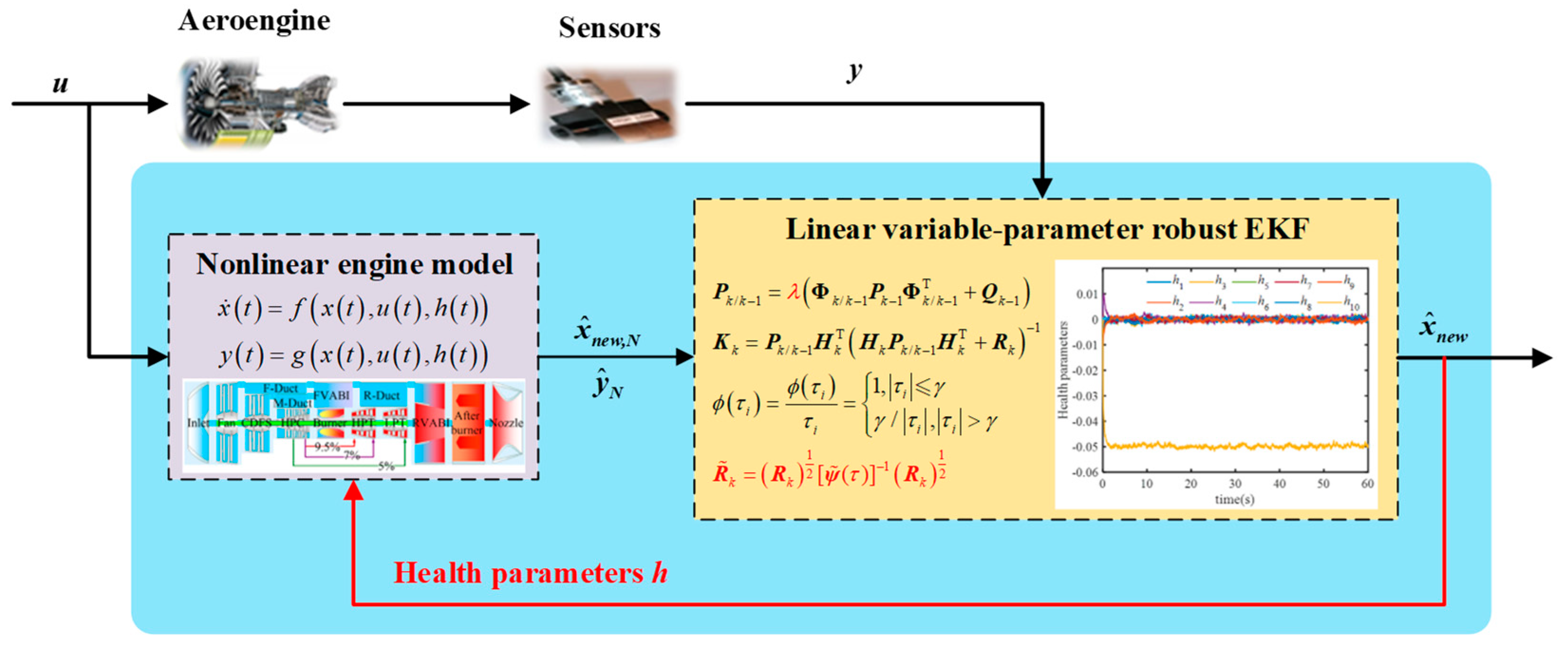
2.2. Improved Hybrid Structure On-Board Adaptive Engine Model
To address the conflict between the accuracy and real-time performance of the onboard adaptive model, the structure of the proposed improved onboard adaptive model is illustrated in
Figure 5. The structure comprises two essential components: the nonlinear engine model and the linear parameter variable REKF. The control input of the aeroengine is denoted as
, and the data stream,
, from the aeroengine sensor to the REKF represents the real measurement data. Data streams
and
from the nonlinear engine model to the adaptive REKF (AREKF) indicate the model’s predicted output, and the output,
, of the AREKF provides state estimation based on real measurements and model predictions.
The dynamic behavior of aeroengines often exhibits highly nonlinear characteristics due to the complex internal physical and thermodynamic processes involved. An advanced nonlinear engine model can be employed to capture these nonlinear characteristics accurately. This model accounts for various internal components, such as the fan, compressor, and combustion chamber, as well as how they interact to produce the overall engine output. Additionally, to simulate various damages and performance degradations that emerge during engine operations, a health parameter, , is introduced to represent the health status of the aeroengine as it changes over time.
An AREKF was designed in this study considering the various uncertainties and disturbances that aeroengines may encounter during actual operation. This filter, building upon the traditional EKF framework, incorporates a forgetting factor and integrates it with the Huber method to estimate the state of the nonlinear system. The inclusion of this forgetting factor enables the filter to better manage and estimate system uncertainties, thereby improving the accuracy and robustness of the state estimation. The Huber method bolsters the filter’s robustness, particularly in cases of unusual observations or noise.
By synthesizing real measurement data with model-based predictions, the AREKF provides a highly accurate estimate of the current state of the aerospace engine. The entire on-board adaptive model structure begins with a real aircraft engine and its sensor data, progresses through preliminary calculations via the nonlinear model, and then merges measured parameters with further accurate estimation through the AREKF. This structure delivers a real-time, accurate, and robust state estimate for the aeroengine, supporting advanced engine control strategies and maintenance decisions.
2.3. REKF Based on Huber Method
Aircraft engines exhibit nonlinear behavior. Both their system and measurement equations are, likewise, nonlinear. EKFs are commonly used to estimate aeroengine states. The EKF utilized in this study employs a Taylor series expansion to approximate the nonlinear system and its measurement equations as a linear system, ignoring higher-order terms, for estimation purposes.
The discrete form of the nonlinear model is:
and the EKF equations are:
where
is the Jacobian matrix used for one-step prediction of the state vector, and
is the Jacobian matrix used for the measurement vector;
denotes the Jacobian matrix,
is the one-step predicted state vector,
is the estimated state vector,
is the covariance matrix for the one-step predicted state vector,
is the covariance matrix for the estimated state vector,
denotes the filter gain, and
is the forgetting factor.
Systems based on Kalman filtering or extended Kalman filtering can experience interference in complex environments, where anomalous observations can severely impact estimation accuracy, resulting in poor robustness. To address these challenges, the Huber filtering method effectively reduces the impact of anomalous observation values on the system and improves its robustness by reconstructing the measurement noise covariance matrix. The Huber cost function, which combines the characteristics of l1 and l2 norms, is the most commonly used in Huber’s proposed M-estimation. It is expressed as:
where
γ is an adjustment factor in the range [
1,
2] and
i falls into the range [1,
m], where
m represents the dimension of the observation.
is the observation residual, which can be obtained by calculating
, where
is the measurement noise covariance matrix,
is the measurement value vector, and
is the observation equation.
The Huber weight function is a commonly used cost function:
The measurement noise covariance matrix can be modified by
to obtain the following:
Replacing the measurement noise covariance matrix in Equation (14) with Equation (10) yields the REKF based on the Huber Method (HREKF). The core principle of HREKF is to reweigh the measurement noise covariance matrix, construct different weights for observation residuals of different sizes, reconstruct the measurement noise covariance matrix, and mitigate the impact of anomalous observations on the on-board adaptive model’s accuracy. This approach significantly enhances the robustness of the on-board adaptive model.
The introduction of the forgetting factor in the robust extended Kalman filter (REKF) framework is essential to balance estimation accuracy and robustness, especially under conditions of uncertainty and environmental variability. Standard REKFs, while robust to some extent, rely heavily on historical data, which can reduce adaptability when faced with sudden system behavior changes—such as engine degradation or unexpected disturbances. In dynamic environments, a standard REKF may respond too slowly, as it gives equal weight to older data that may no longer represent the current system state.
By incorporating a forgetting factor, we dynamically reduce the influence of older data, making the filter more responsive to recent observations. This adjustment allows the filter to maintain high estimation accuracy even under shifting conditions, which is crucial for accurately tracking health parameters in aeroengines. Thus, the forgetting factor improves upon the standard REKF by increasing adaptability and reducing the potential for estimation drift in rapidly changing environments.
3. Adaptive 2DOF Robust Controller Based on LPV Model
3.1. 2DOF Robust Controller
In any real system, uncertainties are inevitable and stem from external interference signals or model uncertainty. External sources of uncertainty include input disturbances, output disturbances, and noise, while model uncertainty refers to discrepancies between the mathematical representation of the system and its physical counterpart (plant) [
32]. Model uncertainty can arise from various factors such as inherent inaccuracies in the nonlinear model, errors in linearization, an unknown model structure, and degradation of plant performance. If left unaddressed, these uncertainties can negatively impact the system’s stability and performance.
We utilized a perturbation block, Δ, to account for the difference between the actual engine and its nominal model. We formulated uncertain models for the engine by incorporating this perturbation block as follows:
which can be rewritten in the form
where
represents uncertain models that include the actual plant model,
denotes the nominal model, and
is the perturbation block.
The block diagram presented in
Figure 6 depicts a closed-loop system with a 2DOF controller. The system consists of a reference input (
r), output disturbance (
d), and two output errors (
) and (
). The closed-loop system is expected to match the ideal model
, and in addition to ensuring internal stability, the two signals
e and
u need to be minimized. The signal
e represents the difference between the system output and the reference model output, whereas
u denotes the control signal, which is crucial for robust stability in the presence of perturbations. Accordingly, two weighting functions are included in
Figure 6 to reflect the relationship between the two penalty signals.
The term “2DOF control” refers to the practice of separately tuning the parameters that optimize the tracking characteristics of the target value and those that optimize the disturbance suppression capabilities using a feedback controller . This approach ensures that the closed-loop system attains internal stability, robust stability, and disturbance suppression. The feedforward controller, , is designed to minimize the difference between the output of the entire system and the output of the reference model M, thereby meeting the tracking requirements and optimizing both characteristics simultaneously.
To standardize the representation, the structure in
Figure 6 was rearranged into the standard structure shown in
Figure 7 by defining
,
, and
. The controller,
K, consists of a feedback controller,
, used for disturbance attenuation and a pre-filter,
, which achieves the desired closed-loop performance. The controller,
K, is expressed as follows:
The interconnected system can be expressed as
where
Mixed sensitivity optimization is a prevalent design problem in practical applications [
33,
34]. We employed this approach in the present study to solve for the 2DOF robust controller. For simplicity, we focus here on the suboptimal design of the system. Given a value of
, our objective is to identify a stabilizing controller,
, that fulfills the following criteria:
The interconnected system is:
where we assume that
The two algebraic Riccati equations are:
and the controller is
where
.
All suboptimal controllers are
and
, such that
.
When there is a direct link between the control input and the measurement output, the controller formulas for “Case D” are as discussed here. We investigated the controller formulas applicable in scenarios where a direct connection exists between the control input and measurement output, referred to as case
. First, we synthesized a controller,
, for the system with
. Subsequently, the original system’s controller,
, can be derived from
and
D by
The state–space representation of the controller
K(
s) can be obtained as follows:
where we assume that
3.2. 2DOF Control System Based on LPV Model
Gain-scheduling control is a technique for managing nonlinear systems by systematically combining a set of linearized controllers, as a form of adaptive control. However, unlike online identification-based adaptive control, it utilizes offline designed scheduling strategies to update feedback parameters offline. The design process involves selecting a range of parameter values that represent the system’s dynamics and designing a linear time-invariant controller for each value. These controllers are then interpolated between operating points to obtain a gain-scheduling controller for the nonlinear system.
The methodology of 2DOF robust gain-scheduling control includes identifying a spectrum of operating points, followed by the derivation of linearized models for the system under both nominal and degraded conditions. Robust controllers are engineered for each of these linearized representations, with considerations for performance degradation. These controllers are strategically scheduled, based on a combination of scheduling and health parameters, to exert control over the system.
Gain-scheduling control is recognized as an effective technique for managing nonlinear systems. Moreover, the integration of robust gain-scheduling control with an emphasis on performance degradation may be highly effective in stabilizing systems in scenarios characterized by performance degradation.
In this study, we developed a gain-scheduling controller for the system described by Equation (1). A set of operating points,
, was chosen to divide the flight envelope into
q regions. At these points, the control input and health parameters are defined as in Equation (14).
where
the
ith selected operating point,
denotes health parameters at
, and
is the control input.
Utilizing the small-perturbation method, we derived a linear model incorporating health parameters at each operational point. This produced linear nominal models of the engine in both normal and degraded states. Subsequently, linear uncertain models for these states at each operational point were constructed by integrating a perturbation block, creating a comprehensive framework for analyzing engine performance under varying conditions.
We developed a method for robust controller design in this study to address the issue of uncertainties inherent to engine linear models. This method involves selecting operating points under both normal and degraded states of the engine, followed by establishing a series of 2DOF robust controllers [
35,
36,
37]. By employing linear interpolation techniques to obtain controller parameters, a closed-loop system with highly robust performance under conditions of uncertainty was established.
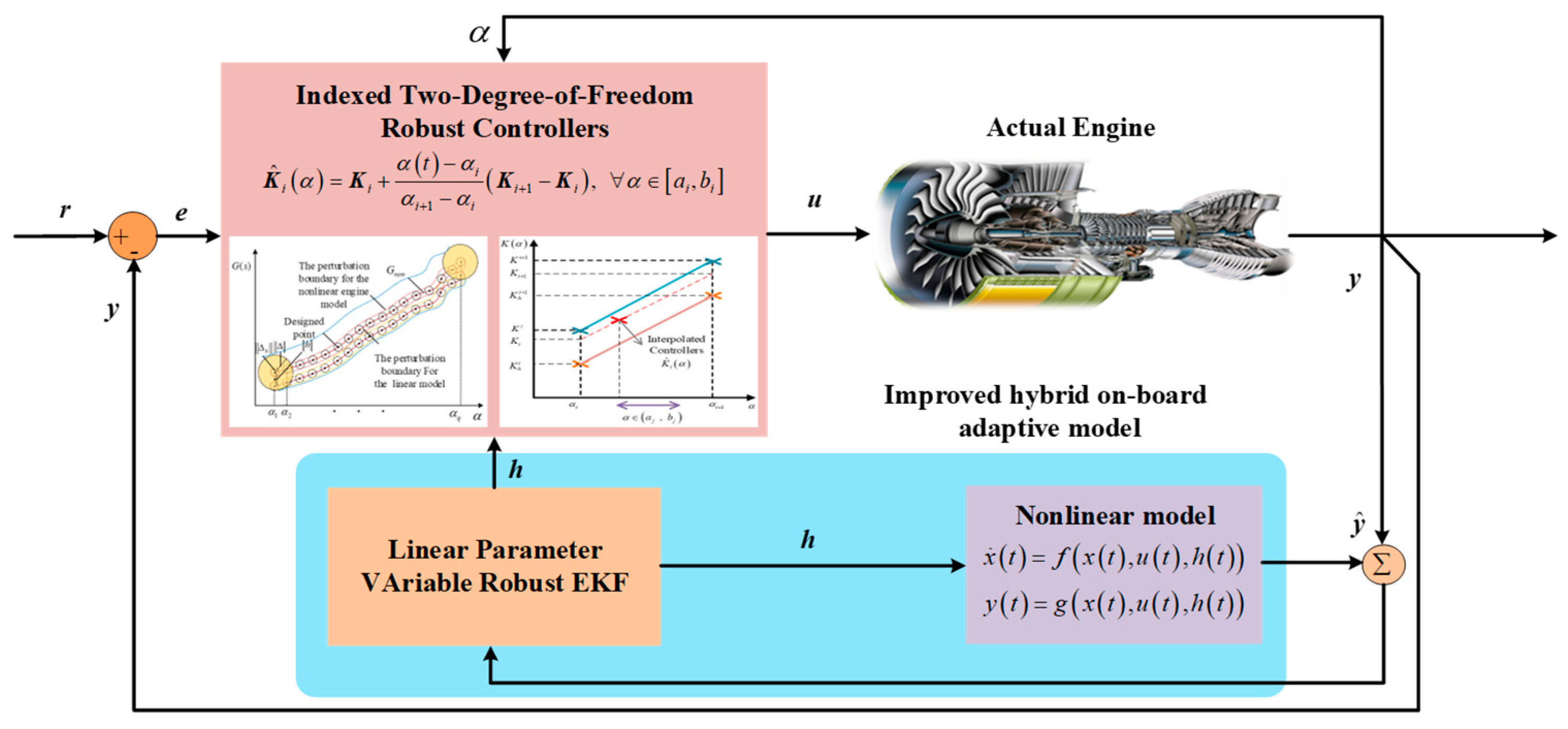
A structural diagram of the gain-scheduling control system is provided in
Figure 8. Within this framework, the scheduling variable
encapsulates the rotational velocity of the engine’s fan. Integral to the control system is the health parameter vector
h, which serves as a quantitative reflection of the engine’s performance degradation.
The operational sequence delineated in
Figure 8 commences with transmission of the actual engine’s input parameter
u and output parameter
y to the on-board adaptive model. Scheduling and health parameters (
and
h, respectively), as deduced by the model, are then utilized to execute scheduling computations. These computations result in an optimally robust controller tailored to the engine’s current state, thereby constituting a comprehensive closed-loop control system.
A set of 2DOF robust controller design schemes was utilized for the purposes of this analysis. Selected working points were linearized in the design process, then the resulting linear models were divided into two modes for controller design: normal mode and degraded mode. The normal mode corresponds to the basic working characteristics of the engine, while the degraded mode corresponds to performance degradation. A robust set of controllers was developed by performing linear interpolation on the controller parameters between these two modes.
The interpolation process included both the scheduling parameter
and the health parameter
ℎ, which is crucial for determining the extent of engine degradation at the chosen operating point
. Linear interpolation was applied to accurately tailor the controller’s functionality to the engine’s performance degradation state
ℎ, including the controllers
and
corresponding to the engine’s normal state and performance degradation state
at the specific operating point
, respectively. This approach ensured a nuanced and precise controller response, tailored to the engine’s current operational condition.
Considering the defined plant
, the stability interpolation method systematically synthesizes controllers in the following manner:
A critical consideration for the practical application of the adaptive two-degree-of-freedom robust gain-scheduling controller (ATDF-RGSC) in aeroengines is its computational feasibility for real-time implementation. While robust gain-scheduling controllers and adaptive models can be computationally intensive, our approach has been designed to minimize these demands and meet real-time requirements.
Firstly, the controller design process, including the robust gain-scheduling and tuning of adaptive parameters, is performed offline. This means that once the ATDF-RGSC is fully designed and calibrated, the real-time computational load during actual operation is significantly reduced, as the controller operates based on pre-designed parameters. This offline design approach ensures that the controller’s computational requirements remain low during real-time execution.
Additionally, to enhance the real-time performance of the onboard adaptive system, we utilize a Linear Parameter Varying (LPV) model in place of a more complex component-level nonlinear model. The LPV model captures the essential dynamics of the aeroengine while substantially reducing computational complexity compared to a full nonlinear model. This substitution ensures that the system achieves a balance between modeling accuracy and computational efficiency, making real-time implementation feasible on aeroengine hardware.
4. Turbofan Engine Example
In this study, simulations were conducted using a nonlinear turbofan engine model constructed through the component method, which accurately captures the dynamic characteristics of each engine component. The turbofan engine model encompasses a detailed representation of key elements, such as the fan, compressor, turbine, and combustor, with specific focus on their interconnections and operational interactions.
To enable control design across the entire flight envelope, this nonlinear model was linearized at multiple operating points, resulting in a comprehensive Linear Parameter Varying (LPV) model. The LPV model provides a structured framework for designing the adaptive two-degree-of-freedom robust gain-scheduling controller, allowing the controller to adjust to variations in engine states and operating conditions, such as changes in altitude, speed, and performance degradation.
4.1. Simulation of Estimated Health Parameters
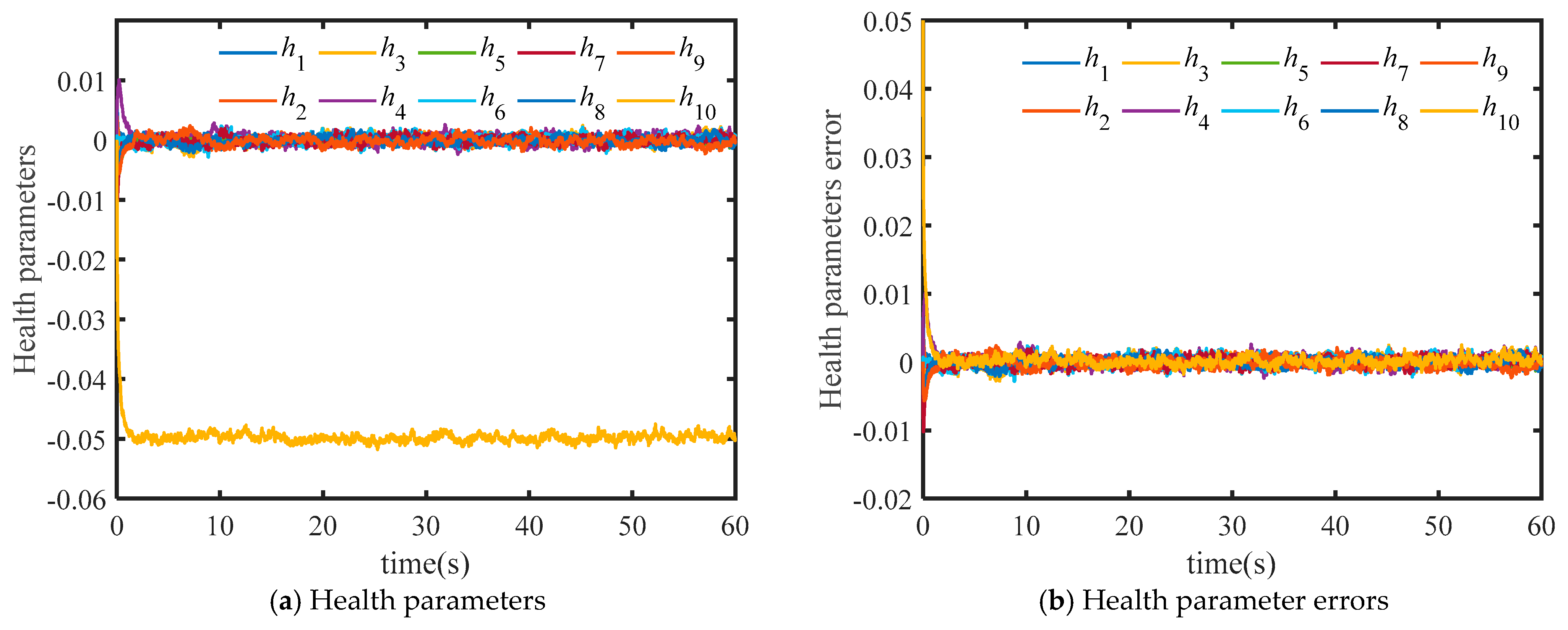
In this study, we established onboard adaptive models using both the REKF and traditional EKF. We utilized both models to estimate health parameters in the event of sensor anomalies and compared their performance across several metrics. The efficiency of the high-pressure compressor within the engine has degraded by 5%, while other components remain unaffected. Specifically, the health parameter
h3 reflects a 5% degradation. The simulation results, as illustrated in
Figure 9 and
Figure 10, confirm the effectiveness of the proposed method.
Figure 9 indicates that the onboard adaptive model based on the REKF accurately estimates degraded engine health parameters.
Figure 10 reveals a significant discrepancy between the health parameters estimated by the onboard adaptive model based on the traditional EKF and the actual health parameters.
Table 1 furnishes a quantitative performance comparison between the two filters. The REKF demonstrates superior performance in terms of its root mean square error (RMSE) of 0.0009, which is approximately 52.6% lower than the 0.0019 RMSE of the traditional EKF. The maximum error of the REKF is 0.0178, which is lower than that of the traditional EKF at 0.0185. The mean error of the REKF is 0.0005, which is 66.7% lower than the 0.0015 of the traditional EKF.
These simulation results demonstrate that REKF can effectively reduce the estimation error of health parameters throughout the engine operation process. The maximum error (Max(e)) of the two filters is equivalent at 0.0500, indicating a similar worst-case scenario. However, given the general trend of RMSE and average error, the REKF proves to be a more reliable means for obtaining accurate health parameters.
The traditional EKF does not effectively approximate engine degradation. The proposed REKF, conversely, can lessen the impact of anomalous sensor readings, thereby assuring more accurate estimations of engine health parameters in the presence of performance degradation and abnormal sensor measurements. This improves the robustness and fault tolerance of the onboard adaptive model to sensor measurement parameters. By utilizing the proposed approach, the engine’s health status can be estimated with greater precision and reliability.
Figure 11 illustrates the impact of the forgetting factor on the estimation performance of the REKF. When λ = 1, as shown in
Figure 11a, the engine experiences degradation at time 0, and the onboard adaptive model successfully tracks the current performance degradation within 5 s. However, the estimation result is significantly affected by noise. When λ = 0.1, as shown in
Figure 11d, the engine experiences degradation at time 0, and the onboard adaptive model successfully tracks the current performance degradation within 13 s. In this case, the estimation result is less affected by noise.
Overall, the simulation results suggest that a larger forgetting factor enables faster tracking of performance degradation but also results in more significant noise interference. By optimizing the forgetting factor, the onboard adaptive model can achieve optimal estimation performance tailored to the specific needs of the system.
4.2. Simulation of Adaptive 2DOF Robust Gain-Scheduling Control
In this research, we have implemented an advanced adaptive 2DOF robust gain scheduling controller, underpinned by an LPV model, on a turbofan engine. This study involved the meticulous selection of 400 operating points specific to the aeroengine, which were utilized for linearization and fitting processes to accurately construct the LPV model. Subsequently, an adaptive 2DOF robust gain scheduling controller was meticulously designed. The degree of performance degradation experienced by the engine is quantitatively encapsulated within the health parameter vector ℎ, providing a nuanced representation of the engine’s operational health.
As an example, consider a scenario where a fan operates at 90% of its full speed at zero altitude and zero Mach number while its efficiency degrades by 2%. The small perturbation linear model of this system is:
where
,
,
, PCNF represents the percentage speed of the fan, and PCNC represents the percentage speed of the compressor.
The designed 2DOF robust controller is:
where
represents the controller state variable, , .
Figure 12 provides a comparative analysis of the tracking response curves and errors for fan speed (as a percentage) under different control systems as engine performance degrades. Operating conditions were set to include a wide range of altitudes and Mach numbers, with fan speed accelerating from 72% to 90%.
The results of this simulation indicate that the adaptive 2DOF robust gain scheduling controller (ATDF-RGSC) outperforms the other two controllers in terms of overshoot and settling time. Specifically, ATDF-RGSC exhibits zero overshoot, while both the 2DOF robust gain scheduling controller (TDF-RGSC) and the traditional robust controller exhibit considerable overshoots of 0.75% and 1.06%, respectively. The adjustment time of TDF-RGSC is 0.42 s, which is 58% and 70% lower compared to the 1.0 s and 1.4 s of the TDF-RGSC and traditional robust controller.
Figure 12b shows where the error curve of ATDF-RGSC is smoother than those of the other two controllers, indicating that it has better adaptability to sudden disturbances or system changes.
Table 2 provides detailed data regarding the response error and steady-state error of the three controllers. The maximum response error value for ATDF-RGSC is 0.0163, which is one order of magnitude lower than those of the other two controllers at 0.6757 and 0.9559. The average steady-state error of ATDF-RGSC is −0.0006, which is also one order of magnitude lower than those of the other two controllers, −0.0089 and −0.0147.
Figure 13 shows the output response curves of the PCNF under different input methods.
Table 3 provides detailed data regarding the response error of the three controllers. At the simulation time of 10 s, a step change occurs in the turbine pressure ratio. Due to the coupling effect between control channels, the PCNF output fluctuates, deviating from the desired value. The RMSE of ATDF-RGSC is 0.00033, which is significantly lower than that of the other two controllers, 0.20425 and 0.27406, respectively. During the simulation period from 20 s to 21 s, the RMSE of ATDF-RGSC is 0.02053, which is much lower than the 0.37380 and 0.51118 of the other two controllers. At the simulation time of 15 s, the PCNF generates a step signal; the ATDF-RGSC has no overshoot and achieves a settling time of 0.4 s, while the overshoot values of the other two controllers reach 0.9862 and 0.6507, respectively.
These results suggest that the proposed ATDF-RGSC is an effective control approach for aeroengines in cases of performance degradation, considering its small steady-state error and overshoot. The ATDF-RGSC demonstrates better overall control performance than the two traditional control methods by comparison.
The proposed adaptive two-degree-of-freedom robust gain-scheduling controller (ATDF-RGSC) incorporates several key innovations that distinguish it from traditional approaches in aeroengine control. First, this method employs a robust extended Kalman filter (REKF) with an added forgetting factor, which enhances estimation adaptability and accuracy under dynamic, uncertain conditions. Unlike traditional extended Kalman filters, this REKF dynamically adjusts to recent observations, making it more effective for handling the variability of aeroengine states over time, especially under conditions of performance degradation and environmental disturbances.
Second, the control design uses a two-degree-of-freedom (2DOF) structure, which is coupled with robust gain scheduling to simultaneously manage both tracking and disturbance attenuation. The 2DOF structure allows for separate control paths: a feedforward path for precise tracking of reference changes and a feedback path for disturbance rejection and stability enhancement. This differs from single-degree-of-freedom designs often used in existing methods, which may have limited flexibility and robustness in multi-input, multi-output (MIMO) systems like aeroengines.
Together, these innovations represent a significant advancement in control design, enabling the ATDF-RGSC to outperform traditional controllers, particularly in scenarios with uncertain, nonlinear dynamics, and performance degradation. This method offers enhanced stability, tracking accuracy, and disturbance management across a broad range of operational conditions, marking a notable improvement over existing approaches.
5. Discussion
The proposed adaptive two-degree-of-freedom robust gain-scheduling controller (ATDF-RGSC) demonstrates strong potential for improving the safety and reliability of aeroengines and other MIMO systems. However, several factors should be considered when evaluating the method’s practicality and effectiveness in real-world applications.
One limitation is that the current model does not account for certain rare or extreme uncertainties, such as sudden environmental shifts, unexpected component failures, or highly nonlinear behavior beyond the range covered by the LPV model. These unmodeled dynamics may impact robustness under specific conditions, and additional adaptation mechanisms may be needed to fully address these scenarios.
Another important consideration is the cost, time, and resources required for industrial implementation. While the offline design of the ATDF-RGSC reduces computational demands during real-time operation, developing and calibrating the controller requires a comprehensive set of engine data across various operational states, which can be resource-intensive. Moreover, the controller relies on accurate sensor inputs and real-time computational capacity, and the adaptation of onboard processors or additional computational resources might be necessary, which could add to implementation costs.
Additional practical challenges lie in managing sensor inaccuracies, actuator saturation, and potential time delays in real-time applications. Although the use of the LPV model and pre-designed controller parameters improves computational efficiency, achieving full adaptability with onboard resources remains a key challenge, particularly in rapidly changing environments. Careful tuning of the forgetting factor within the REKF is also essential to balance adaptability with stability in response to noise and disturbances.
Despite these challenges, the ATDF-RGSC offers notable advancements in handling nonlinear dynamics, performance degradation, and disturbance attenuation. Future research could explore adaptive tuning strategies or machine learning approaches to further enhance robustness and reduce resource requirements, making the controller even more viable for real-world industrial applications.
6. Conclusions
This study developed an adaptive two-degree-of-freedom (2DOF) robust gain-scheduling control methodology tailored to address performance degradation challenges in aeroengines. A robust extended Kalman filter (REKF) with a forgetting factor was implemented to accurately estimate engine health and degradation parameters. Based on this REKF, we established an enhanced mixed onboard adaptive aeroengine model, capable of tracking engine performance degradation with high accuracy. A nonlinear uncertain model, incorporating key engine health parameters, was formulated to rigorously test the proposed method’s robustness and adaptability. To ensure precise control across the entire operational envelope, the engine model was linearized under both non-degraded and partially degraded conditions. A robust controller was designed for selected operating points, with controllers for other operational points obtained through linear interpolation, resulting in the final adaptive 2DOF robust gain-scheduling controller.
Simulation results underscore the robustness and tracking precision of the proposed controller. In comparison to traditional control methods, the adaptive 2DOF robust gain-scheduling controller demonstrated superior performance, exhibiting minimal steady-state error, zero overshoot, and enhanced adaptability under various conditions of engine performance degradation. This control methodology effectively manages aeroengine performance across a broad range of operational scenarios, making it a promising solution for real-world aeroengine applications.
The proposed ATDF-RGSC has demonstrated strong performance in aeroengine applications, but additional testing on diverse MIMO systems will be valuable for further characterizing its adaptability and identifying any limitations or necessary modifications for broader applicability.
While the adaptive 2DOF robust gain-scheduling control method presented in this study has shown substantial advantages, several areas for future research could further improve and expand its applicability. First, future studies could explore real-time implementation of this control approach within a hardware-in-the-loop (HIL) simulation environment, which would offer practical insights into the controller’s performance under true operational constraints. Second, adaptive tuning mechanisms for the forgetting factor and other controller parameters could be investigated, allowing for dynamic adjustment based on varying degrees of engine degradation or environmental disturbances. Additionally, the integration of machine learning algorithms, such as reinforcement learning, could provide more efficient control adaptation by learning from historical data and enhancing robustness against unforeseen anomalies. Lastly, expanding this methodology to other complex multi-input, multi-output (MIMO) systems beyond aeroengines could further validate its versatility and scalability. These future directions will contribute to the continued advancement of robust control methodologies in aerospace engineering, reinforcing the safety, efficiency, and reliability of aeroengines across diverse operational conditions.


