1. Introduction
In recent years, Unmanned Aerial Vehicles (UAVs) have become a research hotspot, finding wide applications in both military and civilian fields [
1,
2]. With the rapid development of aerospace electronic information technology, the tasks undertaken by the Vehicle Management Computer (VMC) have become increasingly complex, leading to a higher probability of failures in flight control systems. Therefore, improving the stability and reliability of the entire flight control system has become an urgent need [
3,
4,
5,
6].
As the core of the flight control system, the VMC is responsible for receiving sensor data, executing flight control tasks, and outputting control commands, directly influencing the overall system performance. To address potential issues during flight and enhance the fault tolerance and reliability of the flight control system, the most effective approach is to start with the system architecture. This involves adopting more stable bus structures and distributed real-time bus architectures to ensure data transmission reliability [
7,
8,
9], as well as employing redundancy techniques to provide fault tolerance, thereby improving the stability and reliability of the entire flight control system.
This paper presents a three-redundancy flight control system based on the M1394B bus by conducting an in-depth study of critical technologies such as reliability, real-time performance, system architecture, and redundancy algorithms in modern flight control systems, combined with the development trends of future redundant flight control systems. Additionally, a novel design concept for the redundant control system is proposed, which includes the design of a system architecture with hardware redundancy, a hierarchical modular software design, a synchronization and decision-making algorithm integrating both hardware and software, and a system reconfiguration algorithm that covers the entire process. Based on the construction of the redundancy system architecture and the design of key algorithms, this paper further designs and implements experiments to validate the decision-making algorithm and system reconfiguration algorithm, demonstrating the advantages of the three-redundancy flight control system in terms of reliability and real-time performance.
The structure of the article is as follows:
Section 2 introduces the research background.
Section 3 discusses the fundamentals of avionics buses and equipment, as well as the design of a triple-redundant flight control system and software architecture based on the M1394B bus.
Section 4 focuses on the redundancy algorithms, including the design and implementation of synchronization, decision-making, and system reconstruction algorithms.
Section 5 presents the experimental validation, outlining the experiments conducted to verify the triple-redundant flight control system and redundancy algorithms. Finally,
Section 6 summarizes the research conclusions, highlighting the significance of this study and potential future work.
2. Analysis of Existing Technologies
Redundancy technology has been widely applied in flight control systems to enhance the safety and reliability of UAVs during mission execution. Common redundancy architectures include dual-redundancy, triple-redundancy, and quadruple-redundancy, each suited to specific application scenarios. Pan and Wu have independently proposed a triple-redundancy flight control system based on the FlexRay bus [
10,
11], exploring the construction of flight control systems using time-triggered buses. Boguslaw Dolega and colleagues proposed a software redundancy solution for UAV flight control systems [
12], focusing on enhancing overall system reliability through software-based redundancy. Zhou et al. analyzed dual-redundancy and triple-redundancy architectures using Markov processes [
13], evaluating the failure rates of different redundancy structures in flight control systems. He et al. introduced a decentralized voting redundancy system successfully implemented in Electric Vertical Take-off and Landing aircraft [
14]. Saied M. examined redundancy management techniques for multirotor UAV actuators [
15], while Saurabh G. explored avionics equipment configuration strategies within redundant flight control systems [
16]. Additionally, C. Yu Wei proposed a redundant flight control system architecture [
17] that enables dynamic reconfiguration of a distributed network and efficient scheduling of system tasks. Wang and colleagues presented a safety assessment process for distributed systems [
18], addressing how to categorize various types of failures and validate software reliability. E. Cliden proposed an avionics system architecture suitable for both distributed and integrated systems [
19], and Insaurralde explored the feasibility of applying reconfigurable flight control computer architectures in avionics systems [
20].
Despite extensive research on redundant flight control systems by past researchers, there remains a lack of a comprehensive, full-process design solution that covers all stages of a redundant flight control system, including system design, software design, redundancy algorithm development, and system verification testing. For instance, the triple-redundancy flight control system proposed by Pan and Wu, based on the FlexRay bus, is limited in application to small UAVs due to the constraints of FlexRay in terms of transmission speed and reliability. Similarly, Boguslaw Dolega and colleagues proposed methods for enhancing reliability at the software level but did not address the overall integrity of the entire redundant flight control system. Zhou, Wang, and others have focused more on the reliability issues within redundant flight control systems; however, their work does not fully address the diverse challenges encountered throughout the design and implementation of a complete flight control system. Other researchers have concentrated on constructing avionics systems within redundant flight control systems or have focused on the application of redundancy in specific aircraft models or particular components of an aircraft.
This paper addresses the shortcomings of previous research on redundant flight control systems and proposes a triple-redundancy flight control system based on the M1394B bus, in line with the development trends of future flight control systems. Compared to previous studies, this system offers several advantages:
Utilization of the M1394B Bus: The M1394B bus features high transmission rates, high reliability, and supports time-triggered mechanisms, making it well-suited to meet the performance requirements of future redundant flight control systems.
Comprehensive Analysis of Different Bus Topologies: The advantages and disadvantages of various bus connection structures are thoroughly analyzed, leading to the design of a triple-redundancy flight control system with a redundant bus, alongside a corresponding software layer design scheme.
Complete Redundancy Algorithm Design: The proposed system includes a comprehensive redundancy algorithm design, covering the Synchronization Algorithm, Decision Algorithm, and System Refactoring Algorithm.
Comprehensive Simulation and Validation Experiments: The effectiveness of the decision-making algorithm is validated through simulation experiments. Fault injection experiments are designed to verify the system’s response time and handling effectiveness under different fault types. Additionally, system degradation experiments are conducted to verify the effectiveness of command output when the system degrades gradually into a single-channel mode under irreversible faults, fully demonstrating the reliability of the triple-redundancy system.
3. Redundant Flight Control System Design
Reliability and safety are the fundamental principles in the design of redundant flight systems, while real-time performance is a basic requirement for flight control systems. In response to the future demands of flight control systems regarding data transmission scale, transmission speed, real-time performance, and reliability, this paper proposes a distributed triple-redundancy flight control system architecture with dual-bus support.
This architecture adopts a design concept of hardware consistency and software similarity, achieving loose coupling among the application layer, redundancy algorithm layer, bus communication layer, and sensor signal layer. The layers interact through abstracted interfaces, and data transmission between devices is carried out via the M1394B bus (Xi’an Qidi Zhikong System Technology Co., Ltd., Xi’an, China). The core processor selected is theMPC8378E (Xi’an Qidi Zhikong System Technology Co., Ltd., Xi’an, China), based on the PowerPC architecture, and the control software operates on the RT-Linux (v.6.11) operating system. Leveraging the characteristics of the M1394B bus, a communication transmission scheme between devices is designed, and the operational processes of the various devices in the system are divided according to time slots.
This chapter first compares and analyzes various bus technologies, concluding that the M1394B bus meets the real-time performance and reliability requirements of this paper. It then introduces the existing hardware foundation, demonstrating that the MPC8378E flight control computer fulfills the necessary usage criteria. Finally, based on the existing hardware, the chapter explores the connection structure of the M1394B bus network, the time division of device operations, and the software design scheme.
3.1. Avionics Bus
M1394B bus technology is one of the most advanced avionics bus technologies available today. It is based on the IEEE-M1394B protocol, which has been optimized and constrained to create the AS5643 protocol. This protocol leverages critical technologies such as data transmission, bus synchronization, and fault tolerance to meet the stringent requirements for real-time reliability and determinism in airborne electronic systems. As a result, the M1394B bus is widely applicable in critical military and aviation systems.
As shown in
Table 1, the M1394B bus exhibits significant advantages over other bus technologies. It employs a Time Division Multiple Access (TDMA) scheme and a bus loop structure, with a maximum network bandwidth of up to 400 Mib/s, fully satisfying the requirements for high reliability, real-time performance, and data transfer rates as discussed in this paper.
In a bus network, the system generally consists of a Control Computer (CC) node, one or more Remote Nodes (RN), and a Bus Monitor (BM) node, all of which are connected through M1394B cables to form a complete M1394B bus network, as shown in
Figure 1.
In an M1394B bus network, node messages are transmitted asynchronously and periodically, with the Start of Frame STOF packet marking the beginning of each bus cycle. During an STOF cycle, as shown in
Figure 2, messages are transmitted. Each node sends its message to the bus data buffer at a pre-configured offset time, while other nodes retrieve the corresponding messages from the bus buffer based on message IDs.
3.2. Fundamentals of Equipment
The VMC serves as the core of the flight control system, responsible for computation and management, and for running the flight control software. It receives input signals from external interconnected devices via the backplane, executes signal management and computation tasks, and generates various control commands and data based on the results, which are then outputted through the backplane. The hardware design of the three flight control computers (A,B,C) is identical, with each flight control computer equipped with an independent processor module, bus interface module, and power module, as shown in
Figure 3.
This paper selects the PowerPC architecture processor MPC8378E, which offers advantages such as the parallel execution of multiple instructions, rapid execution of simple instructions, and pipelined operations [
24]. Through peripheral controllers, it can support multiple communication protocol interfaces, meeting the requirements of various Real-Time Operating Systems (RTOS) for its operating platform [
25].
The equipment currently in our possession, as shown in the
Figure 4, includes three VMCs (Xi’an Qidi Zhikong System Technology Co., Ltd., Xi’an, China), a decision module, multipleservos, a PXI industrial control computer (Dalian Aerospace Power Control System Co., Ltd., Dalian, China), two industrial control computers(Advantech Co., Ltd., Kunshan, China), an M1394B-to-422 conversion module, and several M1394B cables. The three VMCs are identical in hardware configuration, each utilizing an MPC8378E processor and equipped with discrete I/O cards, analog I/O cards, M1394B cards, and synchronization indicators, all running the RT-Linux operating system. The decision module is also equipped with an M1394B card and runs the RT-Linux operating system. Both industrial control machines are equipped with M1394B cards; one operates on the RT-Linux system, while the other runs on Windows 7. The PXI industrial control machine is primarily used to simulate engine actuators, connecting to the bus network through an M1394B-to-422 conversion module. The servos are connected to the industrial control machines via servo controllers and are integrated into the M1394B network for control and communication.
3.3. Triple Redundancy System Design Proposal
In the design of a triple-redundant flight control system, reliability and real-time performance are key factors. During the system architecture and software design phases, it is essential to fully consider the system’s fault-handling capabilities to ensure stable operation. According to civil and military aviation design standards, the failure rate for a typical commercial aircraft must be below /h, for fighter jets below /h, and for common UAV systems, the failure rate should not exceed /h. Since this design is intended for large UAVs, we set a design target for system and software failure rates of no more than /h.
DO-178B [
26] is a guiding standard developed by RTCA, Inc. The standard categorizes software into five safety levels based on the potential impact of software safety and failure on flight operations (as outlined in the
Table 2). In this paper, our objective is to achieve Level A status for the system and software, indicating that a system failure could lead to catastrophic consequences, thereby necessitating the highest level of safety assurance.
Based on the aforementioned background, we have identified three clear design objectives for the triple-redundant flight control system:
In the event of a failure in one VMC, the system must ensure that the remaining VMCs continue to operate normally, allowing the flight mission to proceed without interruption. Even if two VMCs fail simultaneously, the system must still possess sufficient redundancy and control capabilities to ensure the drone can land safely.
The communication bus needs to incorporate a redundant design, such that if a node in the bus fails, it does not affect the command output and information exchange of the VMCs.
The system should have fault reconstruction capabilities. When software failures occur, the system must be able to promptly detect and restore the operating environment of the failed VMC. Additionally, the system should be equipped with the ability to quickly locate hardware faults to ensure that appropriate remedial measures can be taken in a timely manner.
The first two objectives clarify the basic requirements for the system architecture design, while the third objective will be elaborated upon in
Section 4.3. Through the aforementioned design, we aim to develop a triple-redundant flight control system that possesses high reliability and fault management capabilities, meeting the demands of large unmanned aerial vehicles for their flight control systems.
3.3.1. Design Scheme of Single Bus Structure
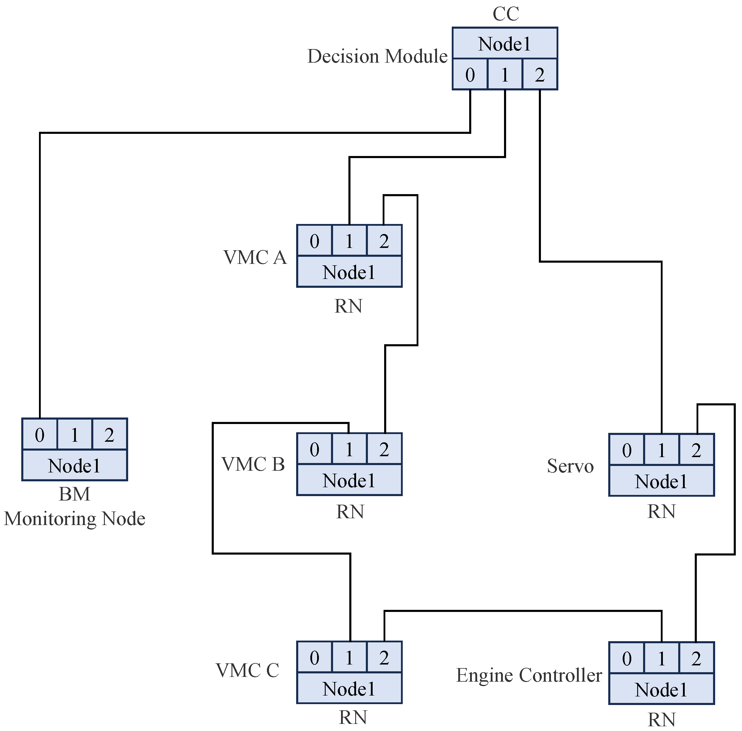
The hardware connections of the M1394B nodes are illustrated in
Figure 5. The actuator serves as the CC node and is responsible for managing the transmission and reception cycles of the bus. Three VMCs, the servo motor, and the engine controller function as RNs and are connected to the decision-making unit via a ring topology. Additionally, the monitoring node is directly connected to one of the root node’s ports.
The triple-redundant flight control system is composed of three VMCs and one decision-making unit internally. Externally, it interfaces with devices such as the monitoring node, servo controllers, sensors, and the engine controller. The M1394 B bus facilitates communication between the three VMCs, the decision-making unit, the monitoring node, the servo controllers, and the engine controller. Additionally, the three VMCs receive sensor data through discrete signals, analog signals, and RS422 serial ports.
As depicted in
Figure 6, the three VMCs first undergo synchronization upon system startup. Once synchronization is achieved, each VMC begins to collect sensor data, exchange and compare the collected information with the other VMC, and monitor the operational status of the other two VMCs. After processing and calculating the collected data, control commands are output via the M1394B bus and submitted to the decision-making unit for voting. The voted data are then re-transmitted through the M1394B bus, where devices such as the servo motors and engine controllers extract the designated data according to message IDs, subsequently controlling the operation of the aircraft and engine models. The aircraft model simulates sensor data, feeding it back to the VMC to complete a closed-loop control process.
3.3.2. Multi-Bus Architecture Design Scheme
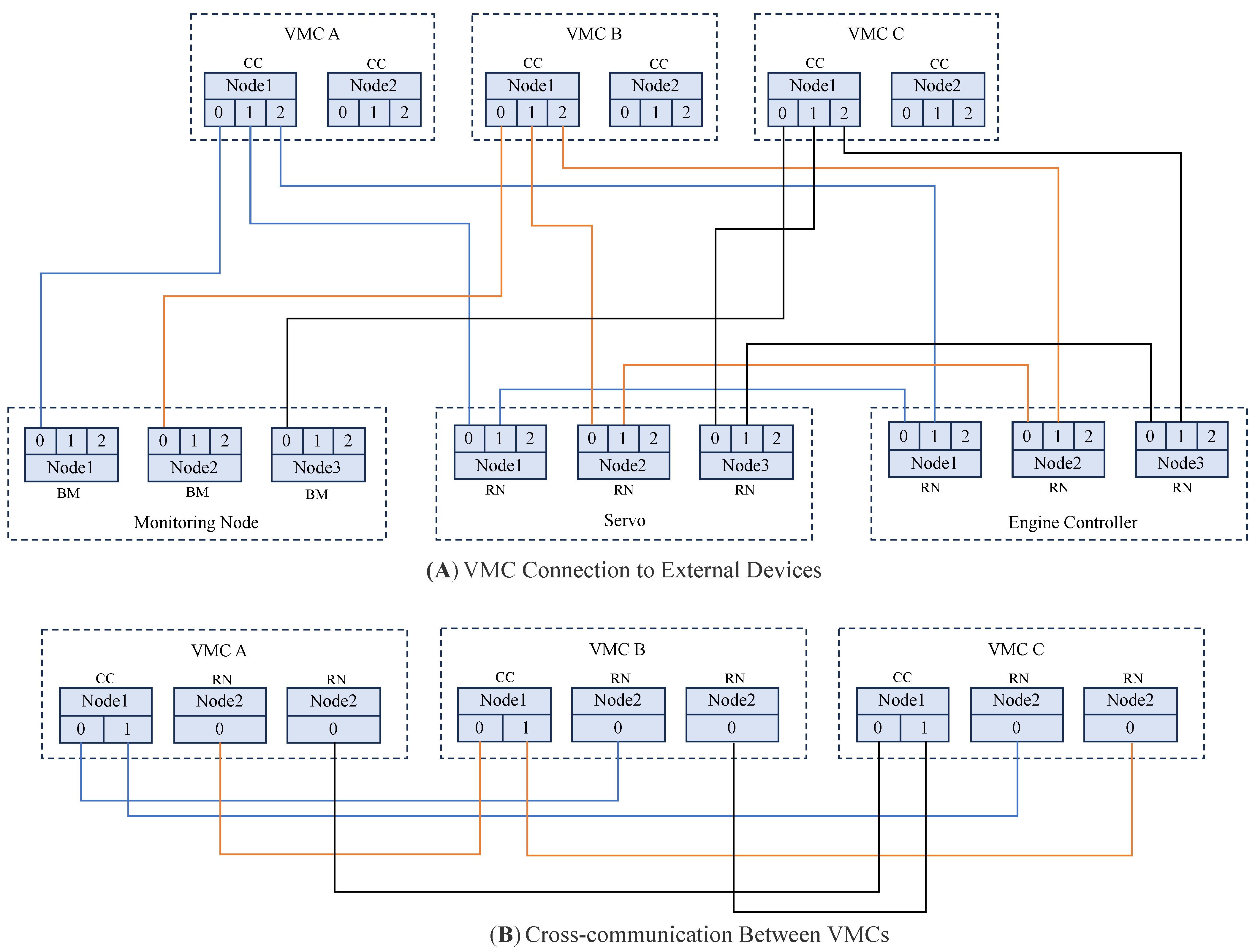
The hardware connections of each M1394B node are illustrated in
Figure 7. The system is divided into two main parts: the first part is the connection between the VMC and external devices, utilizing a three-bus structure. The VMC serves as the CC node, which is responsible for controlling the transmission and reception cycles on a single bus. The servo controller and engine controller function as RN and are connected to the VMC in a ring topology, while the monitoring node is directly connected to one of the VMC’s ports. The second part involves the interconnection between the three VMCs, which also employs a three-bus structure. Each VMC provides three nodes for internal communication, with one dual-port node configured as the CC node and two single-port nodes configured as RN nodes. Each CC node is directly connected to the RN nodes of the other two VMCs, ensuring that each VMC can independently manage cross-communication within the system.
As shown in
Figure 8, after the system is initialized, the synchronization between the three VMCs is first completed. Next, the system begins collecting sensor data and exchanges and compares the collected information among the three VMCs while also monitoring the operational status of the other two VMCs. Once data processing is completed, the system transmits control commands via the M1394B bus. Devices such as the servo controller and engine controller retrieve data from the three VMCs based on the message ID and generate the final control commands through a voting mechanism. These control commands are then used to operate the aircraft and engine models. The aircraft model simulates sensor data, which are fed back to the three VMCs, thereby completing the closed-loop control process.
3.3.3. The Design of a Redundancy Flight Control System with Redundant Bus Architecture
Taking into account the stringent reliability requirements of flight control systems, the simplicity of timing logic design, development difficulty, and the current state of available hardware, a system architecture is proposed that integrates the advantages of both schemes. As shown in
Table 3, the two schemes are compared in terms of bus architecture, timing logic, reliability, and minimum hardware requirements.
By combining the strengths of both schemes, the proposed design incorporates a decision-making mechanism and employs a dual-redundant bus structure. These two buses transmit identical data simultaneously, ensuring that in the event of a failure in one bus, normal communication and data transmission can still be maintained. This architecture effectively enhances data transmission reliability and robustness while simplifying timing logic and reducing development difficulty. It also meets the high safety and availability requirements of flight control systems.
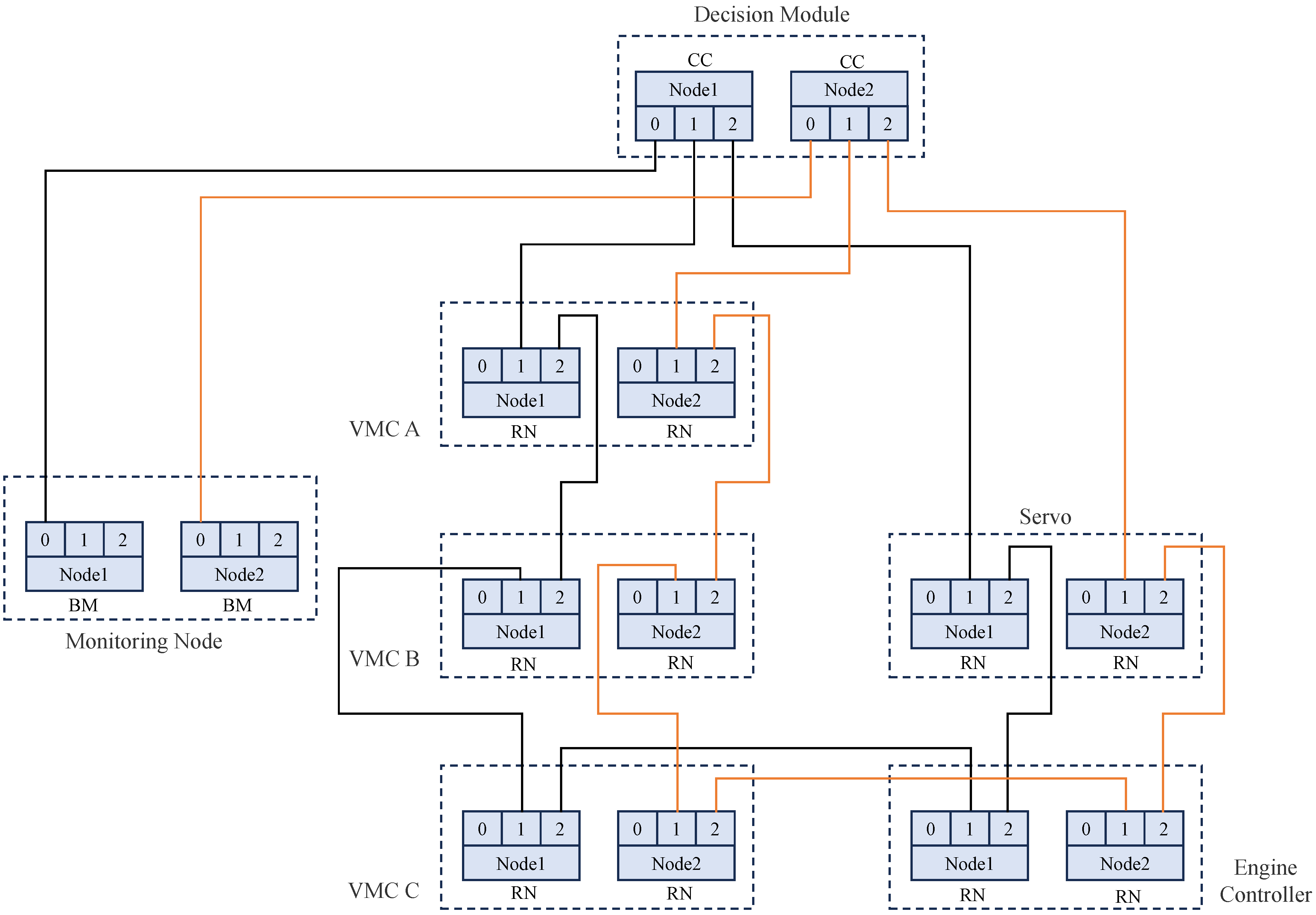
The improved logical connection diagram of the M1394B bus is shown in
Figure 9. The advantages of two bus structures are combined in the improved system architecture. The dual-bus structure ensures high reliability in communication, with the two buses acting as CC nodes through a decision mechanism to achieve consistency in data transmission and timing while retaining the benefits of the decision mechanism. This design imposes low hardware requirements, as the flight control computer, decision-making unit, and external devices only need to support dual M1394B nodes, with each node equipped with three ports. Furthermore, the improved architecture effectively reduces the application layer code on the execution units. For execution units such as servo controllers and engine controllers, the received data directly represent the commands to be executed, simplifying the processing flow and reducing the likelihood of errors.
As shown in
Figure 10, Industrial Control Computer 1 is responsible for running the simulation model and receiving control signal feedback from the actuators. Simultaneously, it transmits the simulated sensor signals to three VMCs via DAOUT and DOUT interfaces. The PXI Industrial Control Computer is used to simulate the engine actuators, receiving control commands from the VMCs through the M1394B-To-422 interface and transmitting the current state information back to Industrial PC 1 via the UDP protocol. The servo motor is connected to the M1394B bus network through Industrial Control Computer 2, and the control surface signals are transmitted to Industrial Control Computer 1 via the RS422 interface.
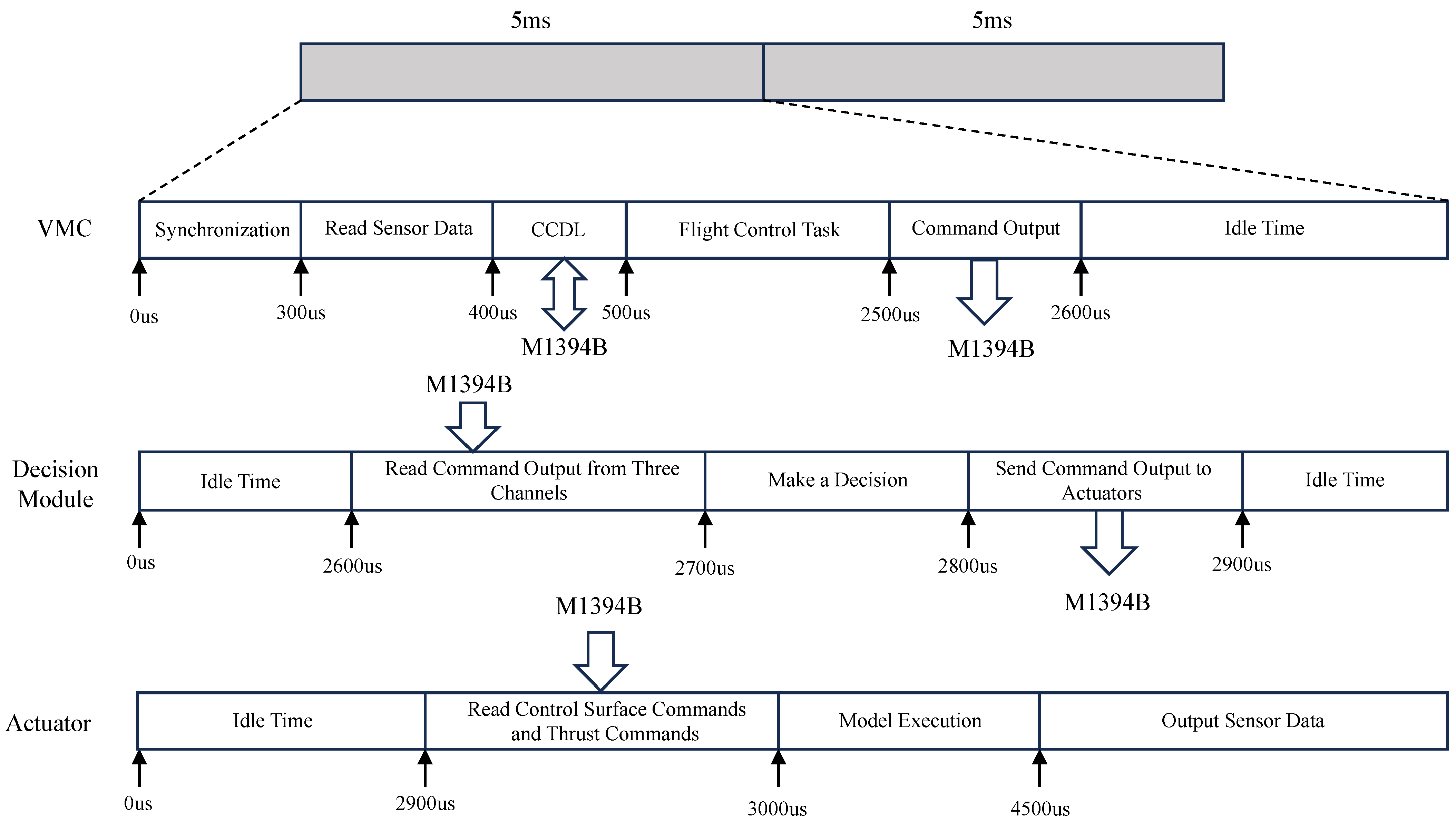
Within a 5 ms operational cycle, tasks such as software data output, data transmission, and control or processing on each device occur as shown in
Figure 11.
At 0 μs, the decision unit sends an STOF packet, marking the start of the bus data transmission cycle. When the three VMCs detect the updated STOF packet, they enter a synchronized operating cycle. The cycle synchronization mechanism ensures that the three VMCs begin operating simultaneously, starting to read sensor data and exchanging internal data. During this time, the three VMCs exchange intermediate state data and the sensor data they have gathered.
At 500 μs, flight control tasks are executed. Once the tasks are completed, the data transmission buffer on the M1394B bus is updated.
At 2500 μs, the M1394B bus begins transmitting updated commands from the three VMCs. At 2600 μs, the decision unit reads the command outputs from the three VMCs and performs decision-making using a redundancy algorithm, updating the transmission buffer afterward.
At 2800 μs, the decision results are updated in the M1394B bus transmission buffer.
At 2900 μs, the execution units read the control surface commands, thrust commands, and other instructions, run the aircraft and engine models, gather sensor data, and transmit them to the three VMCs via discrete or analog signals, completing one simulation cycle.
The transmission scheme based on the M1394B bus is mainly divided into two parts. The first part involves the data sent from the VMCs to the decision unit, as well as the data sent from the decision unit to the execution units. These data include critical information such as control surface commands, throttle execution commands, and start commands. The second part consists of the internal cross-communication between the VMCs, including sensor data collected by each VMC, intermediate state data from the control programs, and data used for redundancy reconstruction algorithms. As shown in
Table 4, a detailed design has been carried out based on the requirements for the communication protocol. The protocol includes elements such as the message ID, sending node, receiving node, and transmission time.
After completing the design of the communication protocol, configure message transmission on the M1394B bus within one STOF cycle according to the message ID and sending node specified in the protocol, as shown in
Figure 12. The data transmission rate of the M1394B bus is 400 Mbps. To ensure the scalability of the communication protocol, the data packet size is fixed at 512 bytes, and the time required to send one packet is 9.8 μs. To avoid data transmission conflicts and ensure compatibility with lower-speed M1394B nodes, the transmission interval is set to 30 μs.
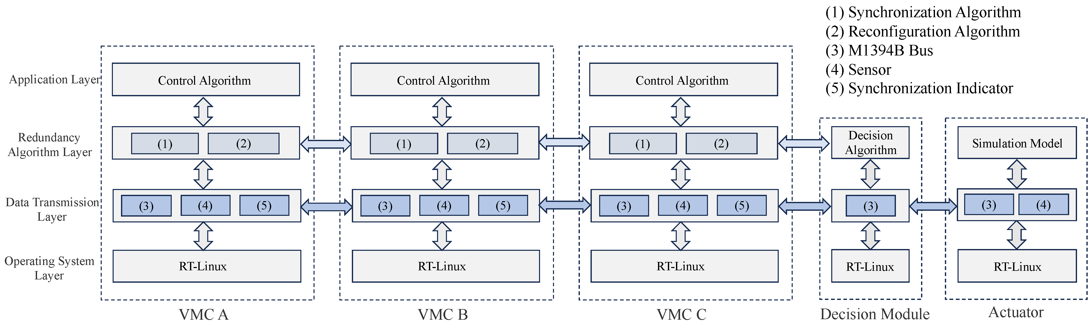
As shown in
Figure 13, in the triple-redundancy flight control system, the flight control software running on the VMC is divided into four layers: the application layer, the redundancy algorithm layer, the data transmission layer, and the operating system layer. These layers are decoupled through abstract interfaces, enabling a loosely coupled design based on data transmission and interface functions. This ensures that each layer focuses solely on the information exchange relevant to its corresponding level.
Specifically, the application layer is responsible for executing flight control algorithms; the redundancy algorithm layer handles synchronization algorithms and system reconfiguration; the data transmission layer collects signals through sensors and uses the M1394B bus to transmit commands and exchange intermediate state data. Additionally, the data transmission layer employs synchronization indicators to transfer high- and low-level signals. This layered design results in a clear structure and modular independence, greatly enhancing the system’s maintainability and scalability.
4. Design and Implementation of Redundancy Algorithm
In the design phase of the triple-redundancy flight control system, we have established the system’s basic structure and operating mechanism. This chapter will delve into the design and implementation of redundancy algorithms, focusing on enhancing the system’s fault tolerance and reliability. Redundancy algorithms are one of the core technologies that ensure the system can continue to operate stably in the face of faults or abnormal situations. This chapter is divided into three main sections: synchronization algorithms, decision algorithms, and system reconstruction algorithms.
4.1. Synchronization Algorithm
The triple-redundant flight control system adopts a distributed architecture, where each flight control computer operates independently, forming a loosely coupled configuration, and communication is achieved through the M1394B bus. Compared to centralized systems, time in a centralized architecture is unique and definitive, meaning that the order of events aligns with the chronological order, thus eliminating synchronization issues. However, achieving time synchronization in distributed systems is particularly challenging. The timing discrepancies between CPU nodes significantly increase the difficulty of coordinated operations, rendering voting operations based on information synchronization meaningless. Therefore, the design of synchronization algorithms becomes essential.
Common time synchronization algorithms include time ordering, relative time synchronization, and absolute time synchronization:
Event ordering is a lower-level time synchronization method that does not require the clocks of all nodes to be perfectly synchronized. Instead, it ensures that the order of events occurring at the nodes remains consistent [
27]. This approach is suitable for scenarios where precise knowledge of each node’s exact time is unnecessary, and only the order in which tasks are executed needs to be distinguished [
28].
In relative time synchronization, each node maintains its local clock and periodically measures the clock offset between itself and its neighboring nodes. By maintaining a conversion table for the timestamps of other nodes, it converts their timestamps to their local time without continuously updating its own clock. Typical examples include Reference Broadcast Synchronization (RBS) [
29] and Pairwise Broadcast Synchronization (PBS) [
30]. This method is mainly used for internal system synchronization and is suitable for synchronization operations within a single VMC.
Absolute time synchronization, on the other hand, requires all nodes in the system to adjust their local clocks during the synchronization process based on reference clock information. This ensures that all local clocks in the system eventually align with the selected reference clock. Representative protocols include the Timing-sync Protocol for Sensor Networks (TPSN) [
31], Average Time Synchronization (ATS) [
32], and Consensus Clock Synchronization (CCS) [
33]. However, for redundant flight control systems, maintaining clock consistency is unnecessary. It suffices for the system to enter task cycles at a unified time, making absolute time synchronization unnecessary.
Considering the characteristics of the flight control system, the three VMCs must enter the task cycle at the same moment. To achieve this, hardware-level interaction signals are processed using synchronization indicators, while a synchronization algorithm is designed to synchronize the three VMCs at the software level.
In the triple-redundancy flight control computer system, there are three primary factors that lead to inconsistencies in the operating cycles of the three VMCs:
Initialization time differences: Although the same software is launched simultaneously on different devices, the time required for initialization varies, resulting in the VMC not entering their operating cycles at the same time.
The accumulated
error of the processor’s crystal oscillator: Although the crystal oscillator error of the processor is within a reasonable range, the accumulated error of the oscillator is intolerable in the flight control system, leading to differences in the number of task cycle executions across the three VMCs.
Thread wake-up delay: Due to delays introduced by the nanosleep function provided by the RT-Linux system, different processors experience varying delays when waking up threads, leading to task threads being awakened at different times.
In terms of hardware, the VMC processor module used in this paper has a synchronization indicator function, which is a prerequisite for achieving three-VMC synchronization. As shown in
Figure 14, the synchronization indicator is implemented using high-speed hardware circuits and has an independent control terminal for transmission. It outputs to the remote VMC via two independent drivers and is equipped with two independent receivers corresponding to the remote VMC.
To address the three issues identified in the synchronization algorithm, we have adopted a start synchronization and a periodic synchronization algorithm with dynamic operating cycles. As shown in
Figure 15, each 5 ms task cycle is divided into five parts. The two key time parameters that need to be determined are the maximum synchronization waiting time and the average synchronization waiting time. By selecting these two parameters appropriately, the average task cycle time can be maintained at 5 ms during long-term operation.
The maximum synchronization waiting time is set to 300 μs, which includes 250 μs for the maximum synchronization signal handshake time and 50 μs for the safety time of the synchronization indicator output low-level signal. The maximum synchronization waiting time accounts for 6% of the total task cycle, with a step-out rate of less than 0.02%, and no continuous step-out events occur.
The calculated average waiting time is 101 μs, including 51 μs for the synchronization signal handshake time and 50 μs for the safety time of the synchronization indicator output low-level signal. The system records the time spent on successful synchronization within an hour of operation, and the calculated synchronization signal handshake time is 51 μs.
The design employs different task times for synchronization success and failure, with self-recovery capability. In the event of a step-out in one cycle, the next cycle can re-synchronize, avoiding continuous step-out. This ensures that both synchronized and unsynchronized devices maintain a task cycle of approximately 5 ms throughout the entire operation.
The implementation process of the synchronization algorithm is shown in
Figure 16. First, the software on the three VMCs starts and performs initialization operations. Then, the system enters the startup synchronization waiting phase, where all three VMCs set their X and Y signals to a high level while simultaneously sampling the signal levels on the other two VMCs. Taking VMC A as an example, when entering the startup synchronization phase, it sets its own X and Y signals to a high level while reading the Y signal from VMC B and the X signal from VMC C. When both signals are detected at a high level, the system exits the startup synchronization waiting phase and enters the task cycle, eliminating the time error caused by different software startup times across the VMC.
After entering the 5 ms task cycle, periodic synchronization begins. At this stage, all three VMCs set their X and Y signals to a high level and detect the signal levels on the other two VMCs. When the signals on the other VMC are detected as high level, synchronization is successful, and the system waits for 50 μs, records the error count, and sets the task execution duration for successful synchronization. If synchronization fails, the error count for the corresponding faulty VMC is incremented. If the error count exceeds 3, the issue is reported, and corresponding measures are taken during the task cycle to determine whether the anomaly is due to synchronization failure or a VMC fault. The task execution duration for failed synchronization is then set. The system subsequently enters the task execution cycle, and after the task is completed, it invokes the usleep function to sleep for the remaining duration, waiting for the next task cycle to wake up.
4.2. Decision Algorithm
A triple-redundant flight control system must be equipped with a voting module to ensure the accuracy of control command outputs across the entire system [
34,
35]. The voting module not only ensures the accuracy of the system’s command outputs but also detects the command outputs from each VMC to determine if any VMC has malfunctioned. Once a faulty VMC is detected, the voting module can promptly isolate and restart the faulty VMC to maintain the system’s anti-interference capability and stability.
This paper presents a sliding window-based improved voting algorithm designed for monitoring and decision-making in system output data. The system’s output commands are primarily categorized into discrete and numerical signals. Discrete data are handled using a voting method, while numerical data are processed using a median voting method, as shown in
Table 5. To enhance the performance of both methods, a sliding window mechanism is introduced. The sliding window size is set to 1000 output cycles, recording the correct output counts for the last 1000 commands. During each task cycle, if the command discrepancy among the three VMCs exceeds a predefined threshold, the system selects the most suitable command for output based on the past correctness counts recorded in the sliding window. Additionally, the data status within the sliding window is updated in each cycle.
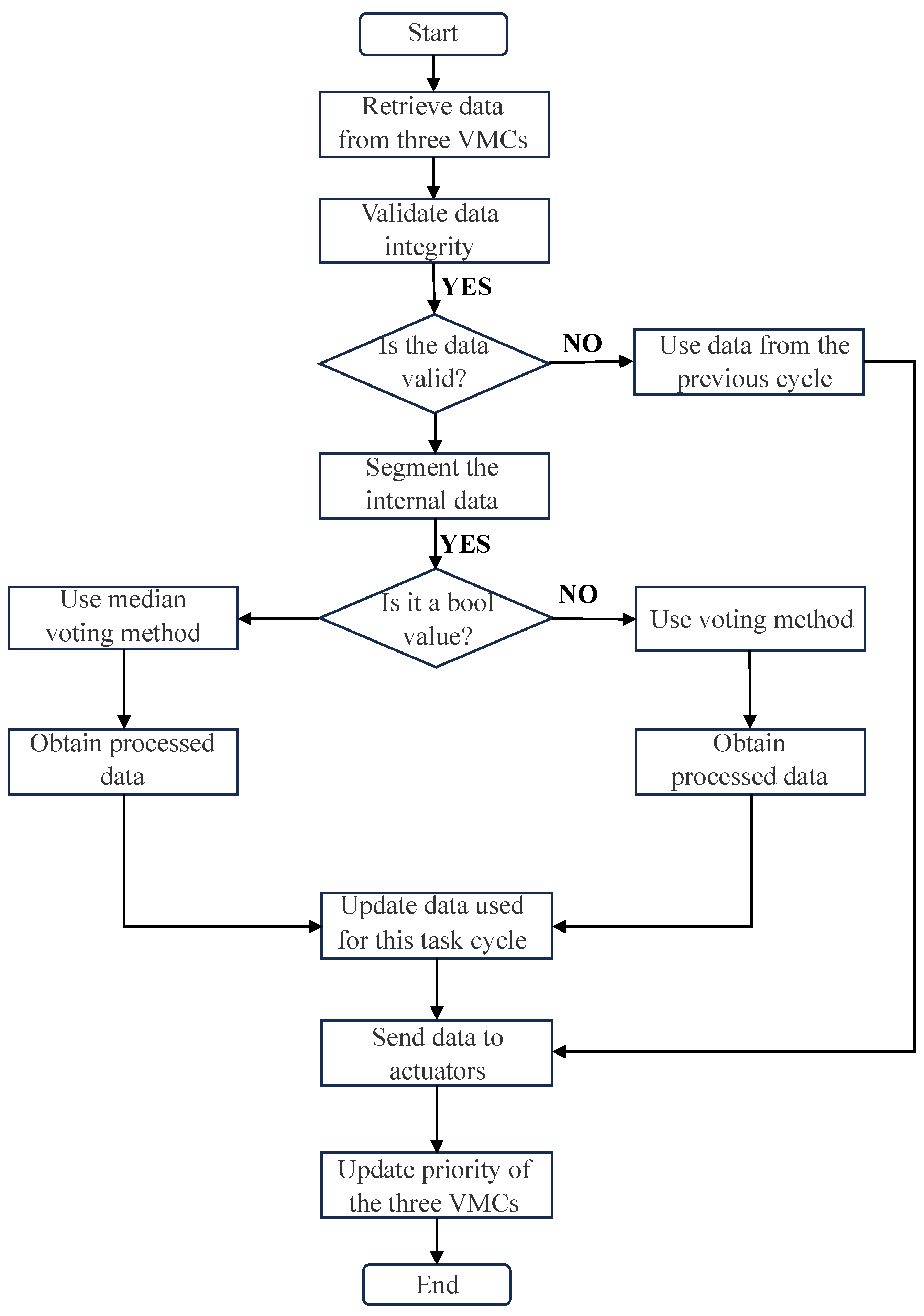
The data processing workflow is illustrated in
Figure 17. After the device is powered on, a communication test is conducted for 1000 cycles to update the data status in the sliding window. During each command output cycle, the system first validates the data; if the number of valid commands is greater than 0, the median voting method or the voting method is applied depending on whether the data are numerical or discrete. Finally, the processed commands are written to the M1394B bus and sent to the respective actuators.
Algorithms A2 and A3 in
Appendix A provide detailed explanations of the sliding window-based voting algorithms. The input includes control commands from the three VMCs and the current task cycle count (TaskCounts), and the output is the processed result. Different processing approaches are taken based on the number of valid data points. When significant data discrepancies are detected, or in cases of tied votes, the system decides which VMC’s output to use by referring to past correctness counts. Furthermore, each cycle invokes the updateSlidWindows function to update the data status in the sliding windows of the three VMCs.
4.3. System Refactoring Algorithm
Fault tolerance refers to the ability of the flight control system to correctly execute specified algorithms even when internal failures occur [
36]. Its implementation is based on the redundancy of hardware resources and the design of reconfiguration algorithms. By employing hardware redundancy, along with appropriate system reconfiguration and recovery strategies, the fault tolerance capability of the flight control system can be effectively improved [
37].
In the design of a triple-redundant flight control system, system reconfiguration is a key component of the redundancy algorithm. The redundancy algorithm enhances fault tolerance without altering the system architecture. With the addition of reconfiguration operations, faults can be promptly identified, isolated, and repaired, enabling the reuse of system resources. This endows the entire system with self-repair capabilities, thereby improving its reliability and stability.
4.3.1. Fault Detection and Handling Methods
As shown in
Table 6, faults occur at each stage of the system’s operation in this study, including the synchronization stage, data acquisition stage, and control operation stage. For each potential fault, reasonable determination criteria are set, and fault handling is carried out when the fault determination criteria are met.
As shown in
Table 7, different types of faults require different handling methods. When addressing faults, it is important to avoid restarting the entire VMC whenever possible. For software-level faults, such as synchronization failures or exceptions thrown during control, it is sufficient to re-synchronize the cycle or restore the context without restarting the VMC. For hardware-level faults, the software layer can first utilize backup buses or sensors, and only if the backup also fails the VMC is restarted, and the board is reinitialized in an attempt to recover the functionality of the bus or sensor.
4.3.2. System Recovery Process
As shown in
Figure 18, the system’s fault detection and recovery process requires the cooperation of three VMCs. Within a task cycle, if a fault occurs in VMC A, data are exchanged via the M1394B bus during the next task cycle to determine whether the fault necessitates a VMC restart. The criteria for this decision include software counters, hardware counters, operation counters, and the reception status of synchronization signals, as defined by the protocol. For faults that require a VMC restart, the system will shut down the VMC and perform system degradation. For faults that do not require a restart, such as sensor faults or failures in a single M1394B bus node, the system records the fault location, stops collecting data from the fault point, and continues data acquisition using other functioning sensors or nodes.
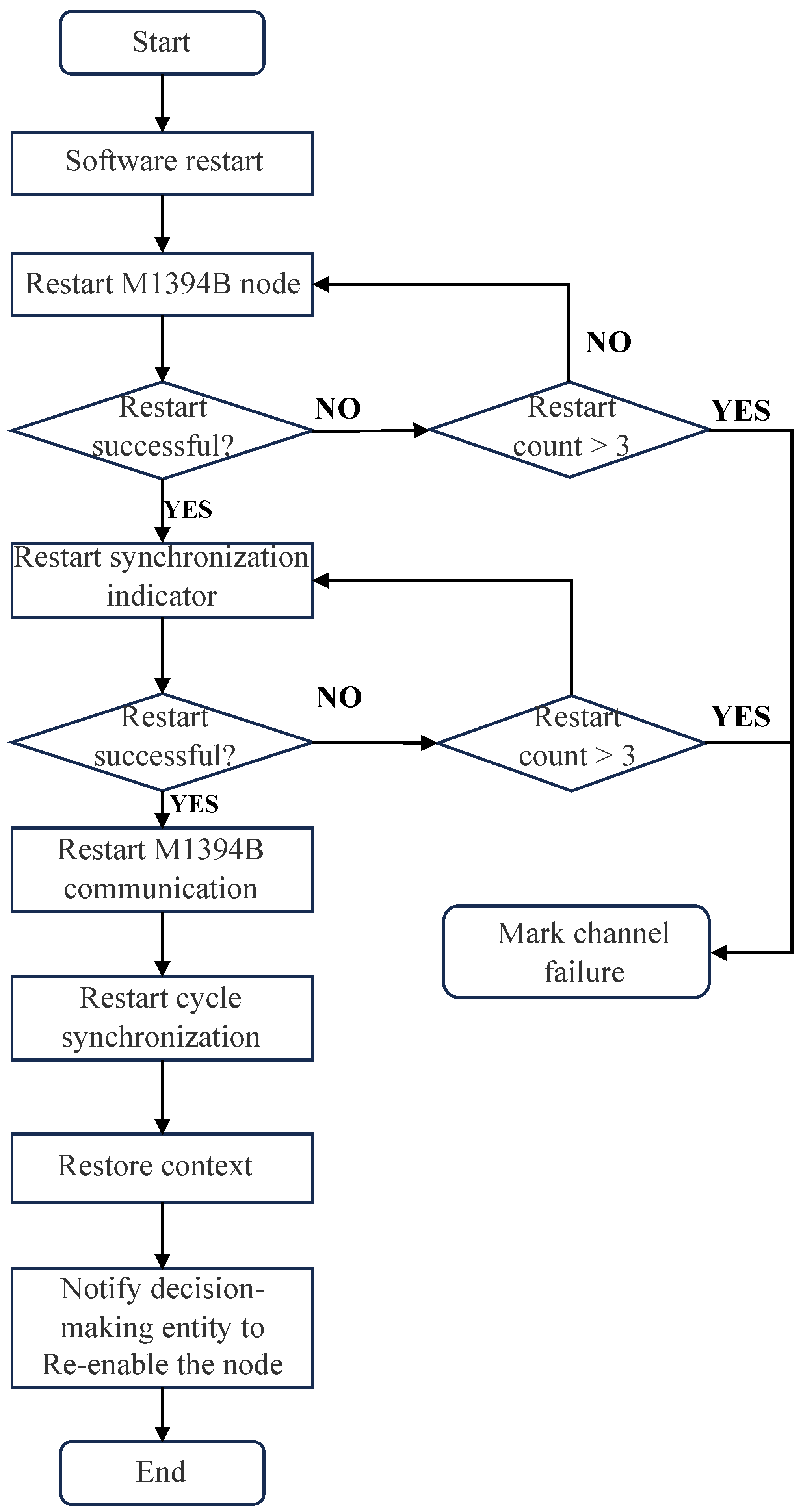
As shown in
Figure 19, a complete fault handling and system restart process is illustrated. For different types of faults, only a subset of the operations in this diagram may be necessary to complete VMC recovery. Below is an explanation of the entire restart process using a fault in VMC A as an example:
When a fault occurs in VMC A, data are exchanged via the M1394B bus in the next task cycle to determine whether the fault requires a VMC restart. This is determined collaboratively by considering factors such as software counters, hardware counters, operation counters, and the reception status of synchronization signals as specified in the protocol.
Based on the collaborative judgment of VMC B and VMC C, VMC A is shut down, and the system is downgraded.
In the restart phase, the flight control software is restarted, followed by the restart of hardware devices such as the M1394B, discrete signal boards, analog signal boards, and synchronization indicators.
In the recovery phase, collaborative work with the other two VMCs is required to restore M1394B bus communication, periodic synchronization, and the operating context.
Restoring M1394B bus communication allows the three VMCs to exchange operational status and sensor acquisition information in a timely manner. This phase takes approximately two task cycles. In the first task cycle, data are used to synchronize the software counters of the faulty VMC with those of the normal VMCs to initiate the recovery of the M1394B node. In the second task cycle, communication between the faulty VMC and the normal VMCs is confirmed to be fully restored.
Periodic synchronization is initiated by monitoring the high-level signals from the other two VMCs through the synchronization indicators. After continuous successful synchronization for three consecutive cycles, the faulty VMC can synchronize its task clock with the normal VMCs.
Finally, the system enters the work context recovery phase. During this phase, the faulty VMC receives intermediate states, task counters, and control law values from the other two VMCs through the M1394B nodes, allowing it to restore its state to match the normal VMCs. This completes the restart and recovery process of the faulty VMC, and the decision-making system is notified that the VMC has returned to normal. The VMC command outputs are re-enabled, and the system is upgraded back to a triple-redundant configuration.
During system operation, the system reconfiguration layer is capable of autonomously detecting and reconfiguring faults in the CPUs of the three VMCs, the input sensors, and the M1394B nodes. The entire system reconfiguration process, from fault occurrence and detection to VMC recovery and system upgrade, requires only 15 to 40 task cycles, ensuring a very short recovery time. As long as no irreversible hardware failures occur, the system can recover in a timely manner, ensuring long-term normal operation in a triple-redundant system state. This maximizes the utilization of hardware resources and ensures the effectiveness of output commands.
5. Validation Experiment
The experimental validation is divided into two parts: decision algorithm validation and system reconfiguration algorithm validation.
For the decision algorithm validation, a simulation process is run to verify whether the maximum error between the output of the command by the three VMCs and the data after the decision-making process meet the required standards. The system reconfiguration algorithm validation consists of two aspects: the first is to verify whether the system can reconfigure in a timely manner when faults occur during the simulation; the second is to verify whether the system can operate in a degraded mode when irreversible faults occur, while also validating whether the system’s watchdog mechanism can restart the VMCs when faults are recovered.
5.1. Decision Algorithm Validation
After the system runs a simulation process under normal conditions, the control commands from the three VMCs and the final control commands used are shown in
Figure 20. In the case of a triple-redundant system, the actuator node receives control commands for the control surfaces and thrust from different VMCs. These commands are processed using a redundancy algorithm to determine their validity, resulting in decision-making data. From the figure, it can be observed that the commands output by the three VMCs closely match the commands after decision-making. There are minor differences between the data from the three VMCs, and the post-decision data are the median of the three VMC commands, indicating the effectiveness of the decision-making algorithm.
As shown in
Table 8, the error between the output of the command by the three VMCs and the final commands used is less than 0.5%, ensuring the reliability of each VMC’s output data.
The experimental results indicate that during the simulation process, the command outputs from the three VMCs are nearly identical, with command errors being less than the preset maximum error of 0.5%. The decision-making mechanism selects the median value to output to the actuators. Additionally, the fact that all three VMCs receive simulation inputs, perform control calculations, and produce simulation outputs simultaneously, further indirectly verifies the effectiveness of the synchronization algorithm and the internal cross-communication scheme.
5.2. System Reconstruction Algorithm Validation
Simulation results based on the decision algorithm were used to conduct system reconfiguration tests, as shown in
Table 9. These tests simulated various input, output, and operational failures occurring at different times to validate the system reconfiguration algorithm’s capabilities. The experiment assessed the time required for fault detection and system reconfiguration, evaluating the algorithm’s response efficiency under different fault scenarios.
As shown in
Figure 21, under the simulation of various faults, the control command output of the three VMCs remains consistent with the preset values. When a fault occurs, the system handles it at different levels depending on the type of fault. In the case of these reconfigurable faults, the entire fault detection and VMC restart process takes less than forty task cycles, ensuring timely fault handling. Moreover, during the system reconfiguration process, the operation of the other two normal VMCs is not affected.
At 50 s, the sensor of VMC A fails, but since the system can obtain sensor data from the other two VMCs, the fault does not affect the command output of VMC A, as shown in the curve
At 100 s, one M1394B node in VMC B fails. Since the system has two M1394B buses, a single M1394B node failure in any VMC does not impact the system. The curve shows that the command output of VMC B remains normal.
At 150 s, another M1394B node in VMC B fails, causing both M1394B nodes in VMC B to become inoperative, preventing normal command output or internal cross-communication. After detecting the fault, VMC B undergoes a restart, temporarily downgrading the system to a dual-redundant system. After approximately 20 task cycles (100 ms), VMC B recovers, and the system is restored to a triple-redundant state.
At 200 s, VMC C experiences consecutive desynchronizations. Upon detecting the fault, VMC C does not require a full restart but only needs to perform synchronization recovery and context recovery. The curve shows that VMC C recovers after approximately five task cycles (25 ms), returning the system to a triple-redundant state.
At 250 s, VMC C encounters an unpredictable fault that causes the software to exit. As the software exits, the destructor function automatically shuts down all hardware resources and clears the work environment, temporarily downgrading the system to a dual-redundant state. The system then undergoes a full reconfiguration process. The curve shows that after approximately 24 task cycles (120 ms), VMC C recovers, and the system returns to a triple-redundant state.
At 300 s, VMC C experiences a predictable fault, causing the control process to exit, but the software remains running. In this case, only control re-initialization, synchronization, context recovery, and fault detection are required to restore normal operation. The curve shows that VMC C recovers after approximately 10 task cycles (50 ms), and the system returns to a triple-redundant state.
Based on the simulation results of the decision algorithm, conduct redundancy degradation experiments as shown in
Table 10 to verify the operating conditions under dual redundancy and single-system configurations.
As shown in
Figure 22, system degradation does not significantly impact the data following decision-making. Even with only a single VMC operational, the system continues to function normally. Meanwhile, the system’s keep-alive mechanism retains its ability to restart and detect hardware failures. In the case of an irreversible failure, the system attempts to restart every 5 s, and if the restart is successful, the system is restored to normal.
At 50 s, VMC B suddenly fails and cannot be restored via a restart. At this point, the system degrades from a triple-redundant system to a dual-redundant one, but it continues to monitor VMC B every 5 s.
At 100 s, VMC C suddenly fails and also cannot be restored via a restart. The system further degrades from a dual-redundant system to a single-VMC system. As observed in the command curve, even after degrading to a single-VMC system, the aircraft’s operation remains normal without significant impact on its status.
Around 150 s, due to the system’s keep-alive mechanism, VMC B’s failure is unexpectedly restored (possibly due to equipment power cycling or the reconnection of the M1394B cable). At this point, the restored VMC B is reintegrated into the system, upgrading the system from single-VMC to dual-redundant.
Around 200 s, VMC C’s failure is similarly restored via the keep-alive mechanism (again potentially due to equipment power cycling or M1394B cable reconnection). The restored VMC C is then reintegrated into the system, upgrading it from dual-redundant to triple-redundant.
The experimental results demonstrate:
During the simulation of the system reconfiguration algorithm, the system is able to promptly detect and locate various types of faults when they occur, followed by handling them according to predefined protocols. The entire fault detection and system reboot process takes no more than 40 task cycles, confirming the reliability of the system reconfiguration algorithm. This ensures the long-term stable operation of the triple-redundant system, allowing for the timely reconfiguration of even minor faults to maintain the normal functioning of the system.
In the redundancy degradation simulation, the system can swiftly isolate the faulty VMC upon fault occurrence, thereby performing system degradation to ensure the normal output of commands and stable operation of the aircraft. Through the system’s keep-alive mechanism, when the faulty VMC recovers, the system reintegrates it and upgrades to a higher redundancy level. This experiment validates the fault tolerance of the triple-redundant system, as well as the effectiveness of the keep-alive mechanism and algorithms in supporting system degradation and upgrading processes.
6. Conclusions
This paper presents the design of a triplex redundant flight control system based on the M1394B bus, aimed at meeting the future demands for reliability, real-time performance, and fault tolerance in flight control systems. The system adopts a design philosophy of hardware redundancy and software similarity, equipped with two time-triggered M1394B buses and three flight control computers utilizing MPC8378E processors. On the software side, the system emphasizes a loosely coupled design, with interactions between different layers facilitated through abstract interfaces.
Subsequently, this paper analyzes the issues that the redundancy algorithms need to address. It designs a synchronization algorithm to resolve clock errors and switching errors, thereby achieving synchronization among the three VMCs; a decision-making algorithm to address command output errors among the three VMCs; a system reconstruction algorithm to ensure the stability of system operations. Through experimental design, simulations of input faults, output faults, and operational faults of the flight control computers were conducted to validate the effectiveness of the redundancy algorithms and the fault reconstruction capabilities.
The research presented in this paper provides new ideas and methods for the design of triplex redundant flight control systems, advancing the study of real-time performance and reliability in flight control systems, and holds significant theoretical and practical implications. Through continuous exploration and innovation, future flight control systems will be better equipped to meet the growing demands for real-time performance and reliability.


