Article

Linear Disturbance Observer-Enhanced Continuous-Time Predictive Control for Straight-Line Path-Following Control of Small Unmanned Aerial Vehicles

1
College of Aerospace Engineering, Nanjing University of Aeronautics and Astronautics, Nanjing 211106, China
2
School of General Aviation, Nanchang Hangkong University, Nanchang 330063, China
3
School of Agricultural Engineering, Jiangsu University, Zhenjiang 212013, China
4
School of Aircraft Engineering, Nanchang Hangkong University, Nanchang 330063, China
*
Author to whom correspondence should be addressed.
Aerospace 2024, 11(11), 902; https://doi.org/10.3390/aerospace11110902
Submission received: 20 August 2024 / Revised: 30 October 2024 / Accepted: 31 October 2024 / Published: 2 November 2024
(This article belongs to the Section Aeronautics)

Abstract

:
This paper studies the straight-line path-following problem on the lateral plane for fixed-wing unmanned aerial vehicles (FWUAVs) which are susceptible to uncertainties. Firstly, based on the natural frame’s location on the prescribed reference paths, the command yaw angle (which is the basis for yaw angle control system design) is solved analytically by combining it with the errors of path following, attack angle, sideslip angle, attitude angles, and geometric parameters of the prescribed reference paths. Secondly, by considering complicated dynamic characteristics, a linear extended state observer is designed to estimate uncertainties such as nonlinearities, couplings, and unmodeled dynamics whose estimated values are incorporated into the continuous-time predictive controllers for feedback compensation. Finally, numerical simulations are conducted to demonstrate the advantages of the proposed method, including reduced tracking errors and enhanced robustness in the closed-loop system, as compared to the conventional nonlinear dynamic inversion and sliding mode control approaches.

1. Introduction

Recently, fixed-wing unmanned aerial vehicles (FWUAVs) have been widely applied in both military and civil areas. In engineering, two main application scenarios, namely, trajectory tracking and path following, are usually encountered. In trajectory tracking, the FWUAVs are required to locate specified spots at a prescribed time point. When tracking complicated trajectories, the air speeds of the UAVs alter frequently, which results in severe energy consumption and low flight efficiency. In contrast, path following (PF) only requires FWUAVs to remain on the prescribed path without time constraints, thus addressing the issues found in trajectory tracking. Therefore, studying PF control techniques for FWUAVs is both meaningful and significant for engineering applications.
The PF control system of the FWUAV consists of two cascade subsystems, which are a gravitational center position control subsystem and an attitude control subsystem. The idea of PF control is to use attitude angle to manipulate following errors such that the FWUAV can fly along the prescribed path. The gravitational center position controller (GCPC), which takes prescribed reference paths as input, aims to generate command attitude signals using the PF errors. Then, the deflection angles of the control surfaces as well as the control laws for steering the FWUAV are designed accordingly. It can be seen that the purpose of the GCPC is to generate command attitude signals and the attitude controller is responsible for generating control laws for manipulation of the FWUAVs.
FWUAVs feature complicated aerodynamic characteristics, variable coupling, fast time variation, and challenges in control system design. Currently, most previous work on the GCPC has focused on building movement models which form the foundation for controller design. In [1], the Newton–Euler approach was applied to establish a plant model. This method requires detailed information such as mathematical expressions of aerodynamic forces/torques, couplings between variables, and nonlinearities. As a result, it leads to challenges such as long design periods, low development efficiency, and high costs.
To this end, two approaches, namely the geometric approach and the control technique, have been presented to build an alternative plant model known as the PF kinematic error model. These approaches do not require any model information and offer a simple structure, making control design more convenient. Consequently, the two approaches provide significant advantages in both theoretical research and engineering application compared with the commonly used approaches.
The geometric approach uses PF errors, flow angles, and attitude angles to compute analytical solutions of the command attitude signals. Representative approaches include line of sight (LOS) [2,3,4,5,6,7], vector field [8,9,10,11,12,13], virtual target following [14,15,16,17,18], and L1 guidance [19,20,21,22,23].
In the control technique, a Frenet frame also known as a natural frame is defined with its origin located on the prescribed reference frame. The Frenet frame moves with the FWUAV, aligning with the body frame of the UAV if the prescribed reference path is followed accurately. Therefore, similar to steering airplanes, the error orientation angles between the two frames can be used to manipulate the PF errors. In the Frenet frame, the control technique builds model information through axial PF error differential equations that treat the error orientation angles as system inputs. These equations only include directly measurable and computable variables such as flow angles, Euler angles, and geometric characteristics of the prescribed reference paths. In addition, due to the merits of combining different control theories to design the command attitude signals, the control technique has attracted extensive attention in recent years. The recently used control theories contain L1 adaptive control [24,25], L1 state feedback control [26], nested saturation control [27,28], linear model-based predictive control [29,30], optimal control [31,32], and nonlinear model predictive control [33,34].
However, a non-negligible problem is that FWUAVs are susceptible to external wind, which would deteriorate the PF performance. Thus, to enhance closed-loop system capability against wind, robust PF control approaches have emerged, including a new guidance law combined with pure pursuit and LOS [35], a VTP-based nonlinear guidance law [18], optimal control with the wind amplitude available [36], feedback control with wind estimation and compensation [31], and adaptive backstepping control [37].
Despite the achievements of the aforementioned approaches, two significant flaws still exist. First, the whole PF control scheme is incomplete. Existing research has mainly focused on building the kinematics of the PF error and deriving command attitude signals while neglecting the important attitude control design problem. Additionally, the deflection laws for the control surfaces have not been addressed. Second, the approaches to improving PF performance are limited. Most previous work has concentrated on reducing the impact of wind acting on the GCPC. However, the attitude control plays a decisive role in the PF control. The PF performance depends on the performance and quality of the attitude system such that the attitude control cannot be neglected.
To address these issues and improve the accuracy of PF for FWUAVs in the lateral plane, this paper presents a robust PF control approach. The PF control performance can be improved using only a small amount of rough dynamic model information. The main contributions of the paper are twofold.
  • The PF control scheme for the FWUAV is perfected.
In this paper, the attitude control technology is studied, and by designing the position control law based on position error, the desired attitude angle is obtained.
2.
A robust control approach is proposed for attitude control.
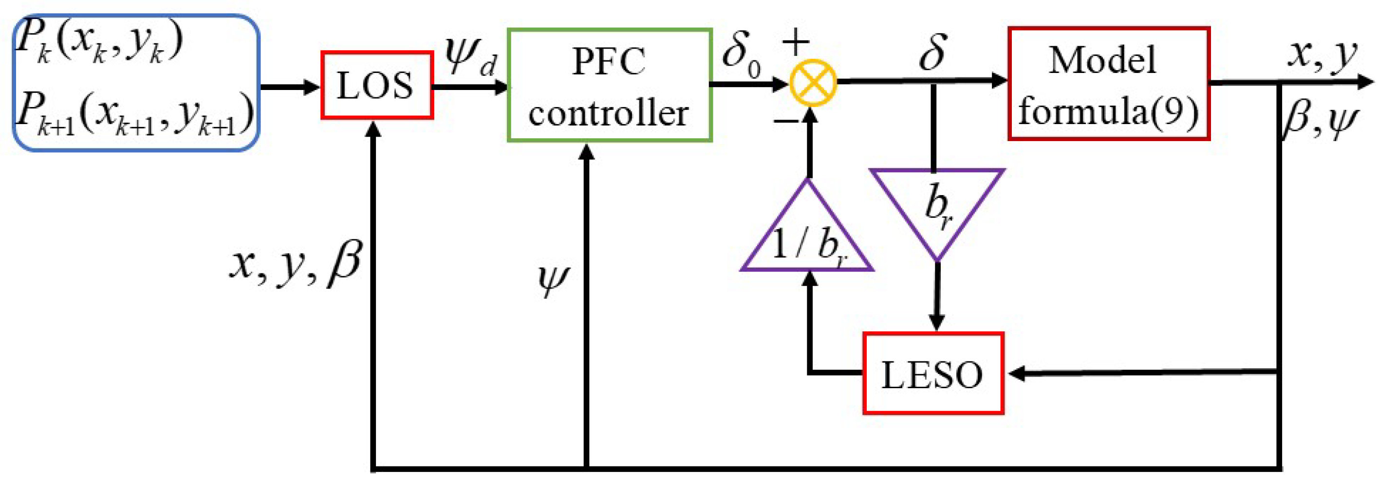
First, a linear extended-state observer (LESO) [38,39,40,41] is applied to estimate uncertainties such as nonlinearities, strong couplings, and time variations. Second, a continuous-time predictive controller is designed for the nominal system in the absence of uncertainties for improving system input/output performance. Last, the estimation of the uncertainties is incorporated into the predictive controller for feedback compensation such that the closed-loop system’s robustness can be improved.
This paper is organized as follows. Section 2 introduces basic theories for UAVs in straight-line PF on the lateral plane and system modeling for latitude movement. At this stage, an outer loop control system for PF is designed. In Section 3, an attitude control system is designed, which includes the development of the LESO and the predictive function controller, with the stability proof provided in Appendix A. In Section 4, numerical simulations are conducted. In this study, the proposed method is compared with the traditional nonlinear dynamic inversion (NDI) and sliding mode control (SMC) approaches to illustrate its superior effectiveness. Additionally, numerical studies with perturbation analysis are conducted, where model parameter perturbations varying by 30% and −30% are carried out. The paper ends with the conclusions in Section 5.

2. System Modeling

In this section, basic theories for the straight-line PF on the lateral plane are shown.
In Figure 1, x E O y E is the earth frame and x b P y b is the body frame. ψ represents the yaw angle, which can be obtained directly from the sensors. u and v are axial velocities in the body frame. Δ is named the look-ahead distance. β and V a represent the side-slip angle and the airspeed, which can be calculated by
β = arctan v u V a = u 2 + v 2

2.1. Command Yaw Angle

From Figure 1, the prescribed reference path orientation angle α k can be given by
α k = arctan 2 y k + 1 y k , x k + 1 x k
where arctan 2 * is the quadrant function.
Take P k as the origin. Then, rotating the frame x E O y E by α k anticlockwise yields the prescribed reference path frame in which the PF error can be given by
e = x x k sin α k y y k cos α k
By recalling Figure 1, the intermediate variable γ d can be computed by
γ d = α k + arctan e Δ
where the important parameter look-ahead distance Δ can be designed adaptively by
Δ = λ 2 + e 2
where λ is a tuning parameter.
From Formulas (4) and (5), the intermediate variable γ d can be re-written as
γ d = α k + arctan e e 2 + λ 2
In addition, we also have
ψ d + β = γ d
Combining Formulas (6) and (7) yields the command yaw angle
ψ d = α k + arctan e e 2 + λ 2 β

2.2. System Modeling for Latitude Movement

By referring to [42], the latitude system model can be given by
ϕ = p ψ = r p = 1 2 I x ρ V a 2 S b C l 0 + C l β β + C l r b p 2 V a + C l δ a δ a + C l δ r δ r + d p = 1 2 I x ρ V a 2 S b C l 0 + C l β β + C l r b p 2 V a + d p f p + ρ V a 2 S b C l δ a 2 I x b p a δ a + ρ V a 2 S b C l δ r 2 I x b p r δ r = f p + b p a δ a + b p r δ r r = 1 2 I z ρ V a 2 S b C n 0 + C n β β + C n r b r 2 V a + C n δ a δ a + C n δ r δ r + d r = 1 2 I z ρ V a 2 S b C n 0 + C n β β + C n r b r 2 V a + d r f r + ρ V a 2 S b C n δ a 2 I z b r a δ a + ρ V a 2 S b C n δ r 2 I z b r r δ r = f r + b r a δ a + b r r δ r
where ρ , S , and b are air density, wing area, and wing span, respectively. I x and I z are the movement of inertia. δ r and δ a are rudder and aileron deflection angles, respectively. p and r are the roll and yaw rates, respectively. The uncertainty terms d p and d r contain unmodeled dynamics and parameter perturbations. C i 0 , C i β , C i r , C i δ a , C i δ r , and i = l , n are aerodynamic coefficients for the FWUAV. The values of the aerodynamic coefficients for the FWUAV are shown in Table 1.
Denote the following: X 1 = ϕ , ψ T , X 2 = p , r T , F X = f p , f r T , G X = b p a b p r b r a b r r , U = δ a , δ r T . Then, Formula (9) can be written in the following compact form:
X 1 = X 2 X 2 = F X + G X U Y = X 1

3. Design of Robust Control Scheme for Yaw System

3.1. Design of the LESO

Treat F X as an uncertainty; then, according to [43,44], the LESO for the system estimating F X can be designed as
E 1 = Z 1 X 1 Z 1 = Z 2 β 1 E 1 Z 2 = Z 3 + G X U β 2 E 1 Z 3 = β 3 E 1
where Z i and i = 1 , 2 , 3 are states of the LESO with Z 1 estimating X 1 , Z 2 estimating X 2 , and Z 3 estimating F X .
The principles for the determination of β i and i = 1 , 2 , 3 are given by
ω 0 > 0 β 1 = 3 ω 0 , β 2 = 3 ω 0 2 , β 3 = ω 0 3

3.2. Design of the Predictive Controller

In designing the controller [45,46], Z 3 is used to replace F X . The prediction of system output Y within the predictive period τ can be given by
Y t + τ = Y + τ Y + τ 2 2 Y = X 1 + τ X 2 + τ 2 2 Z 3 + G X U
Then, the command output in the predictive period τ can be given by
Y d t + τ = Y d + τ Y d + τ 2 2 Y d
The following cost function is taken:
J = 1 2 Y t + τ Y d t + τ T Y t + τ Y d t + τ + 1 2 λ U T U
where λ > 0 is called a penalty factor.
Then, according to the necessary condition J U = 0 , the control law U is given by
U = τ 2 2 λ + τ 2 2 2 G T X G X 1 G T X Y d + τ Y d + τ 2 2 Y d X 1 + τ X 2 + τ 2 2 Z 3
The schematic of the control scheme with uncertainty estimation and prediction functions is given in Figure 2.
A stability analysis of the closed-loop system analysis is given in Appendix A.

4. Numerical Simulations

This section aims to demonstrate the effectiveness of the proposed control scheme with two sets of numerical simulations generated. To show its superiorities, comparisons between the proposed approach, NDI approach [47,48,49], and SMC approach [50,51,52] are conducted. Equation (17) outlines the design of the conventional nonlinear dynamic inversion controller for yaw angle control. The parameter in the LESO is set as ω 0 = 100 . The predictive period is set as τ = 0.5 . During the simulation, the wind velocities along O x E and O y E are 0 and 3 m/s when 20   s t 40   s , respectively. The uncertainty term is d r = 4 sin 0.5 t + 3 cos t when 80   s t 120   s .
r d k = ρ 1 ψ d k ψ k δ r k = 1 b r ρ 2 r d k r k f r k
where ρ 1 > 0 and ρ 2 > 0 are two tuning parameters.
The trimmed states are V a = 30   m / s , x b = y b = 0 , ψ = r = 0 , and δ r = 0 . The values of the controller parameters for the NDI are ρ 1 = 5 and P 2 = 2000 , 400 .

4.1. Case Study 1

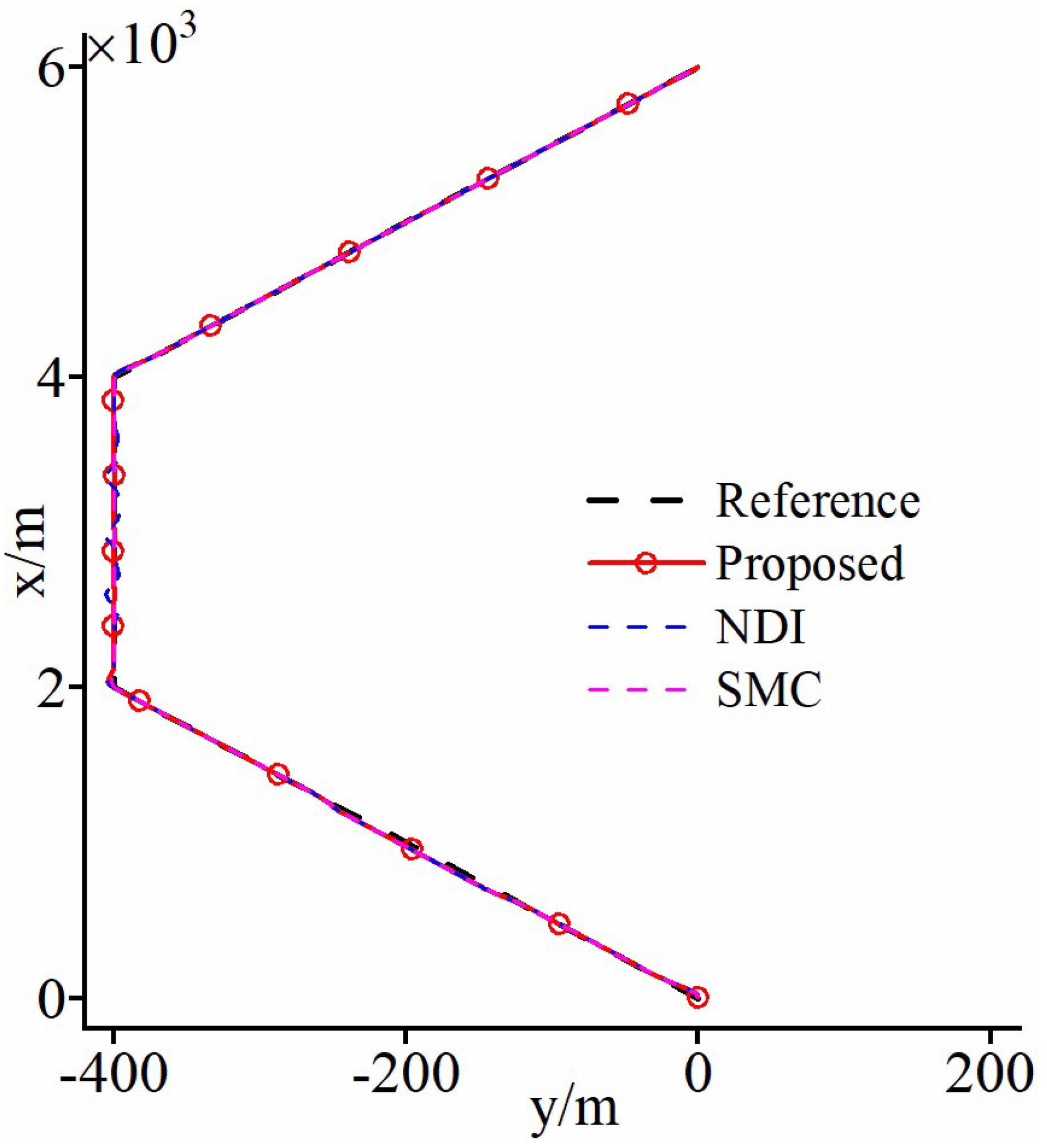
The points of the desired straight-line path (unit: m) that the FWUAV should be located on are P 3 = 4000 , 400 , P 2 = 2000 , 400 , P 3 = 4000 , 400 , and P 4 = 6000 , 0 . The simulation results are illustrated in the following.
The merits of the proposed approach compared with the conventional NDI method and SMC are twofold.
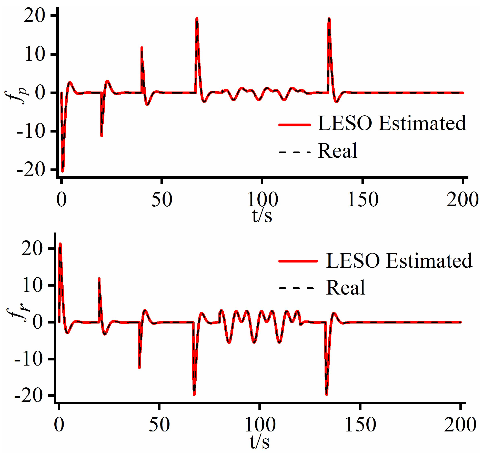
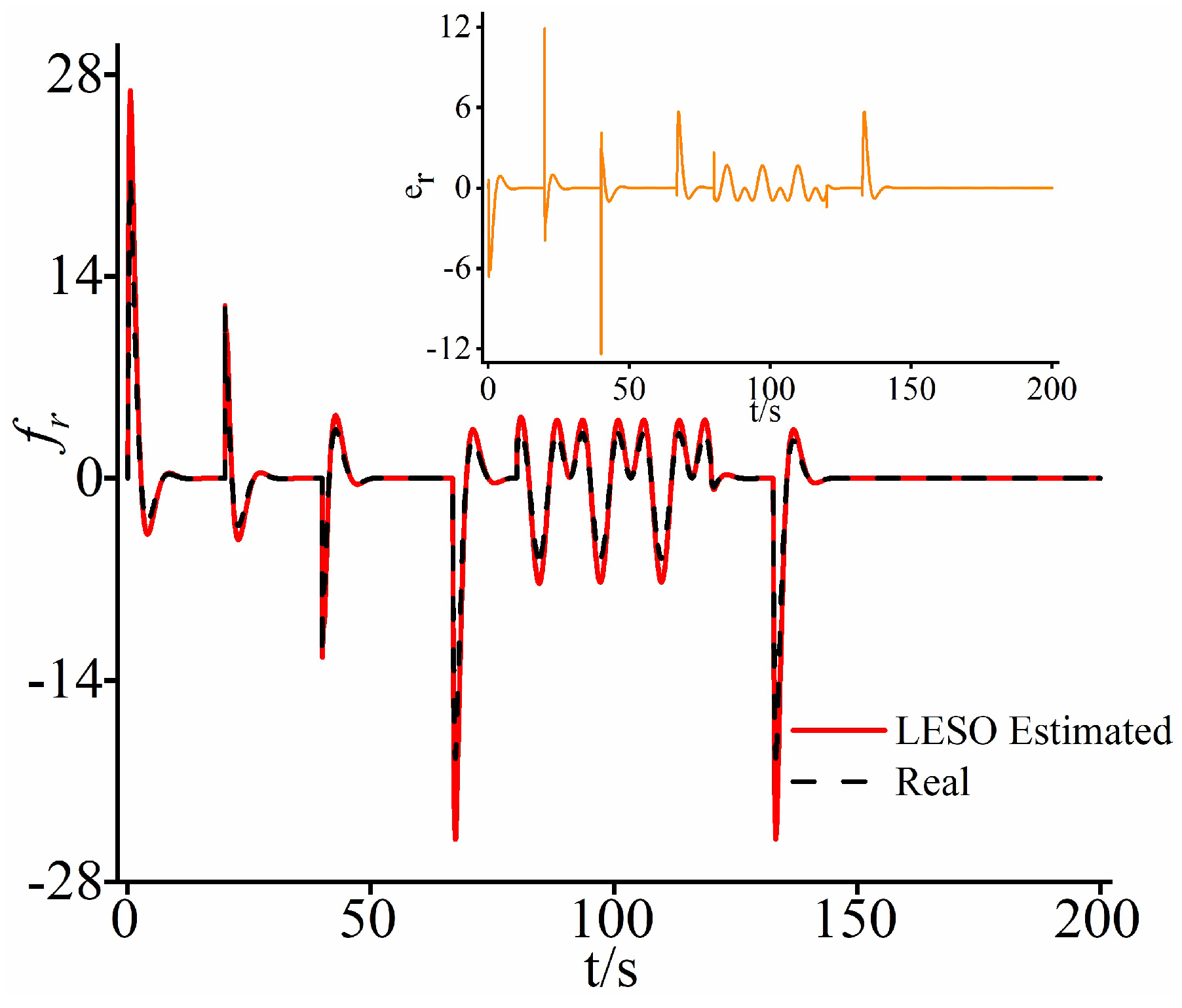
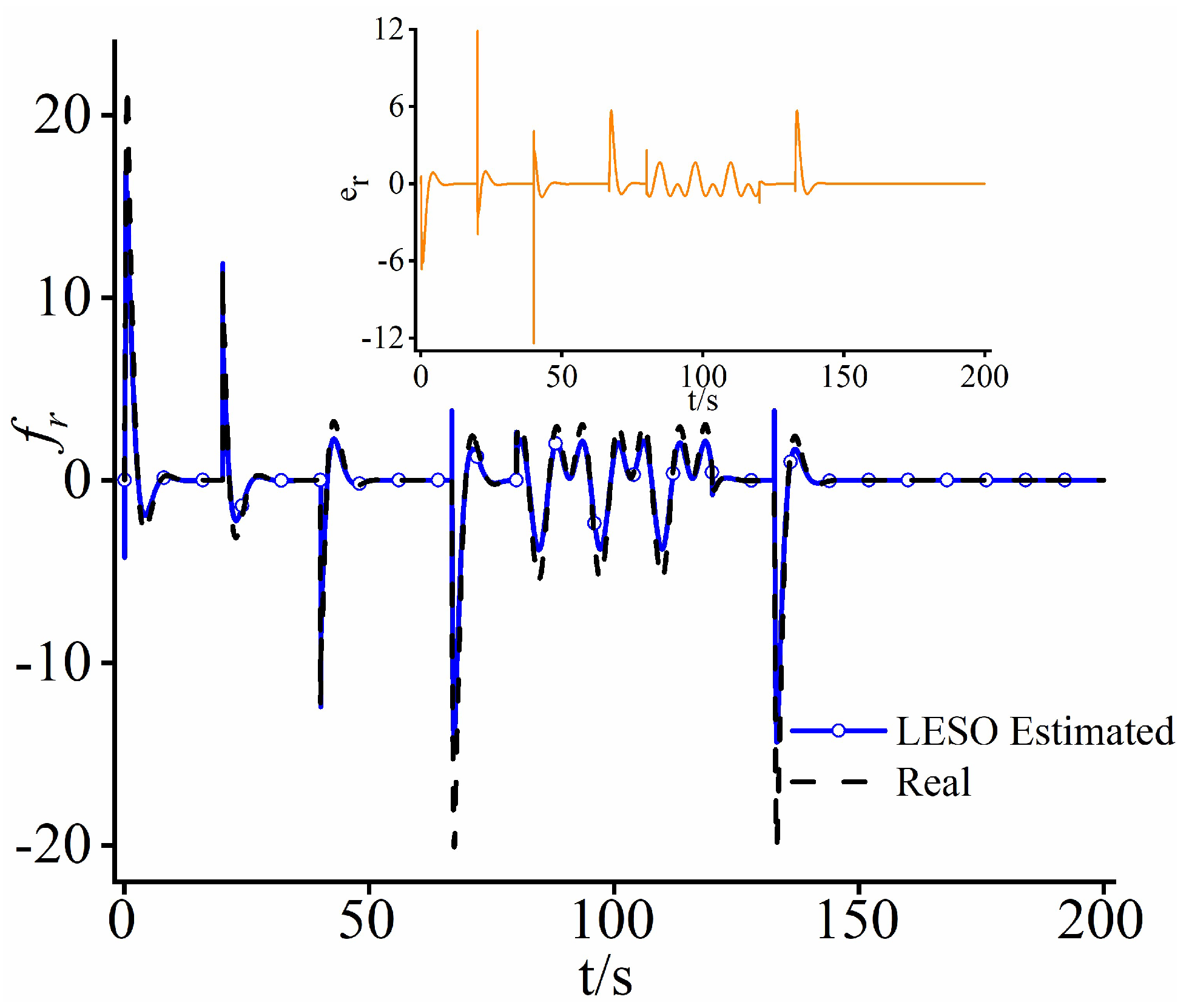
First, as depicted in Figure 3 and Figure 4, under the uncertainties d r when t 80   s , the PF error based upon the proposed approach is reduced to 0.6 m. However, for the conventional NDI method, the PF error is high, up to 6 m, in the period t 80   s , which means that the following precision from the proposed approach is much higher than the one from the conventional NDI method. Although SMC offers good control performance, it suffers from buffeting. The main reason for the clear advantages of the proposed method lies in the higher tracking precision in yaw angle control. Specifically, the yaw angle control system based on the proposed approach employs LESO for real-time online estimation of uncertainties including d r , as shown in Figure 5. The estimated results are then fed back for compensation, allowing for accurate cancelation of d r . Hence, the proposed approach has smaller impact from d r than the conventional NDI method on the yaw angle control system. The conventional NDI method lacks anti-disturbance mechanisms, resulting in poor robustness of the closed-loop system. This leads to significant yaw angle tracking errors (maximum value is high up to 4° for the FWUAV under d r ).
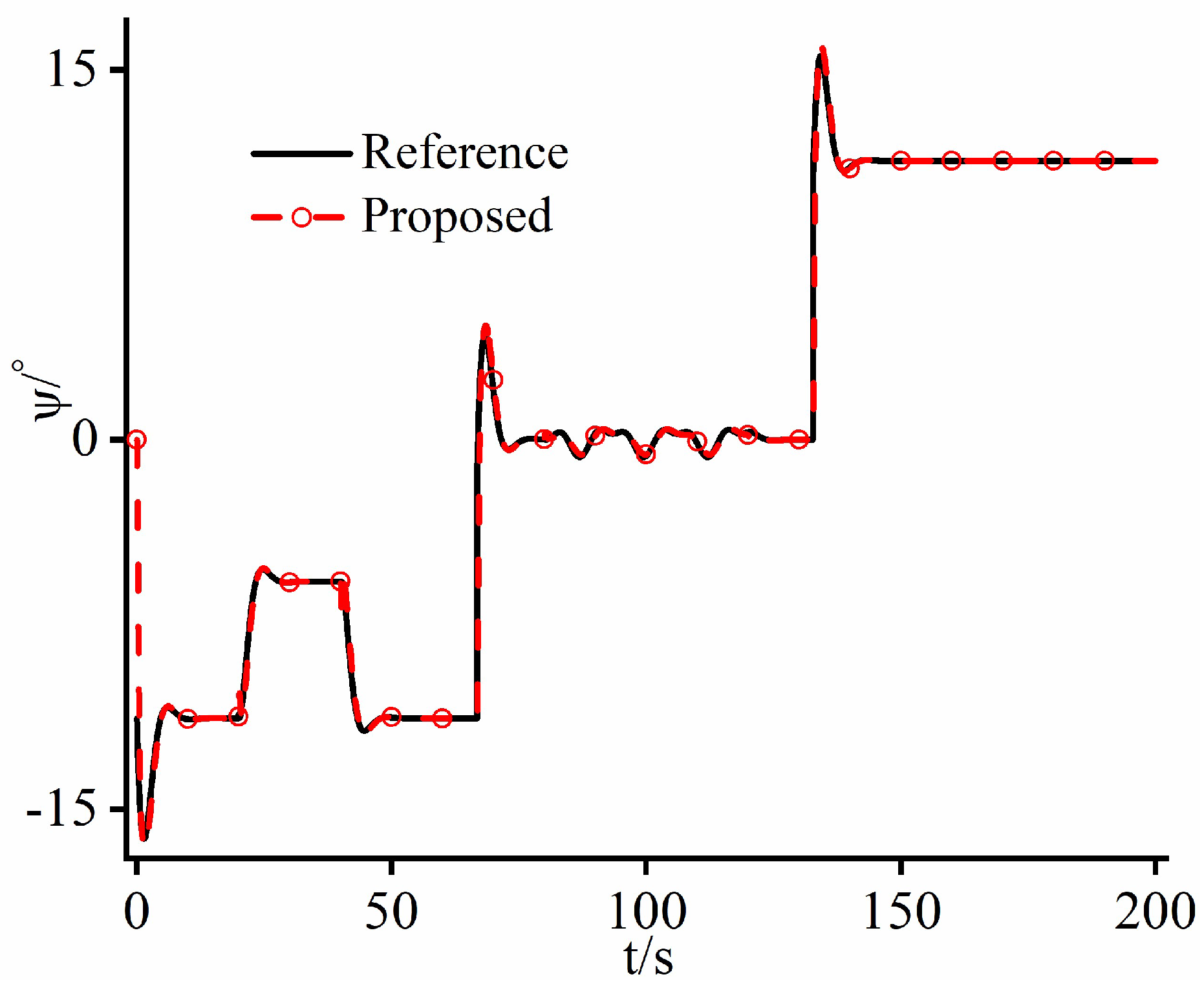
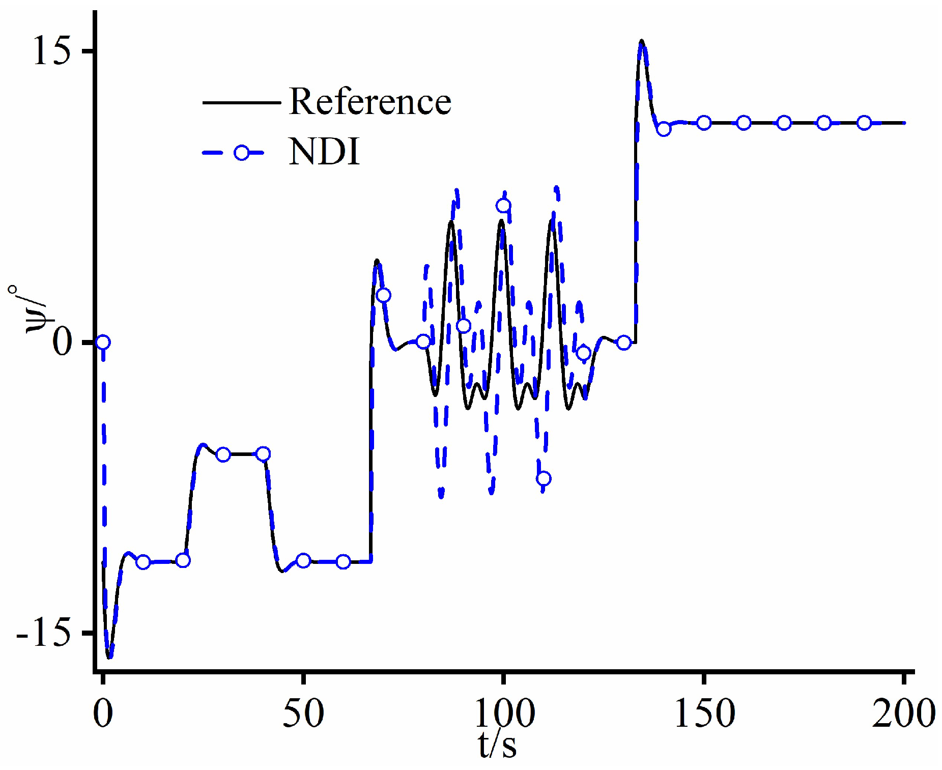
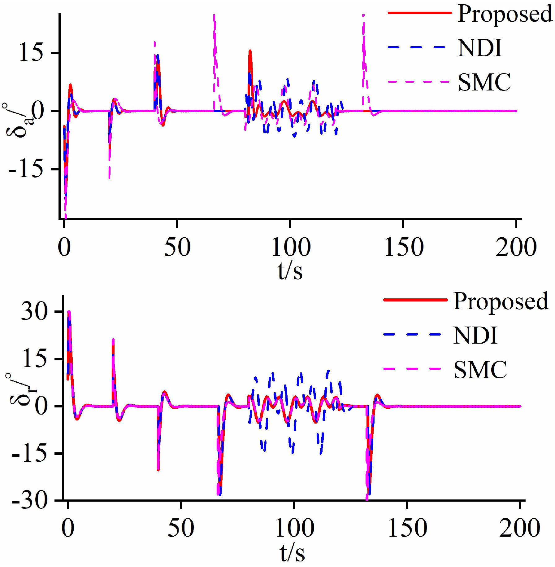
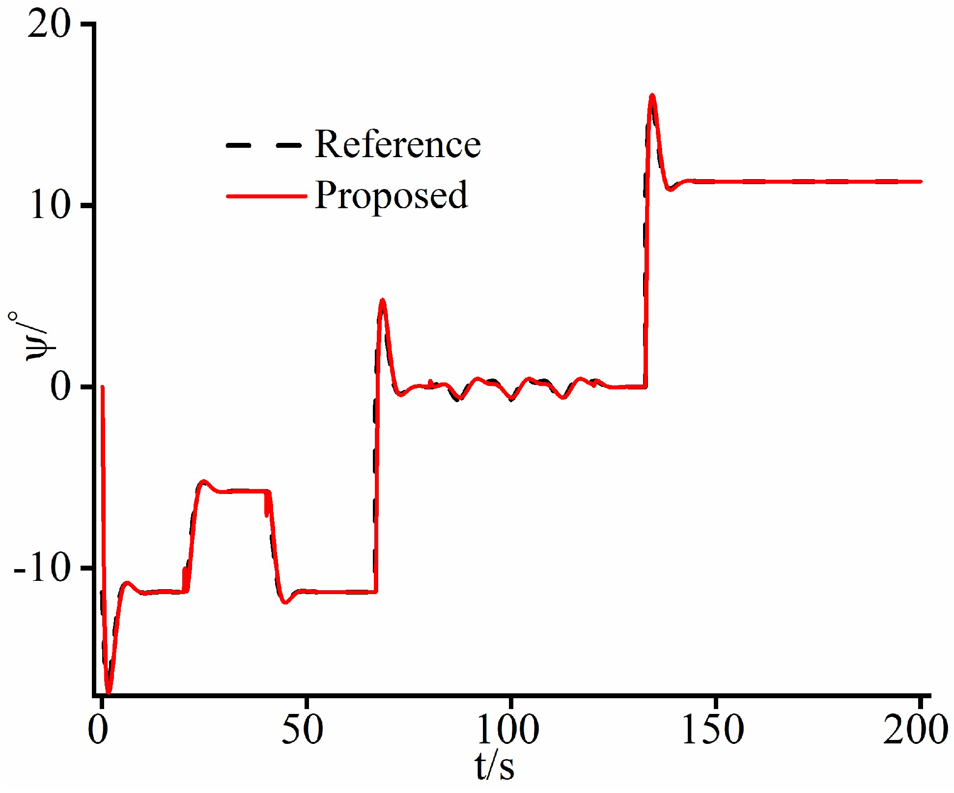
Second, as shown in Figure 6, Figure 7, Figure 8 and Figure 9, under the control of the proposed approach, the yaw angle fluctuations of the aircraft are minimized to 0.6°. Meanwhile, the NDI method is high up to 8°, characterized by high oscillation frequencies and large amplitudes. This indicates that the stability of the aircraft based on the proposed method is significantly superior to that of the NDI method. Since the NDI method lacks disturbance handling mechanisms, its closed-loop system has poor robustness against disturbances. This results in significant oscillations in control inputs δ a and δ r at a certain frequency, as shown in Figure 10. The substantial yaw rate oscillations shown in Figure 8 are also induced. The large yaw angle oscillations shown in Figure 7 are caused consequently. In addition, as shown in Figure 10, the control inputs of the proposed approach are smoothened by the predictive function, resulting in smaller fluctuations in rudder deflection angles. This significantly enhances the tracking accuracy of the yaw angle.

4.2. Case Study 2

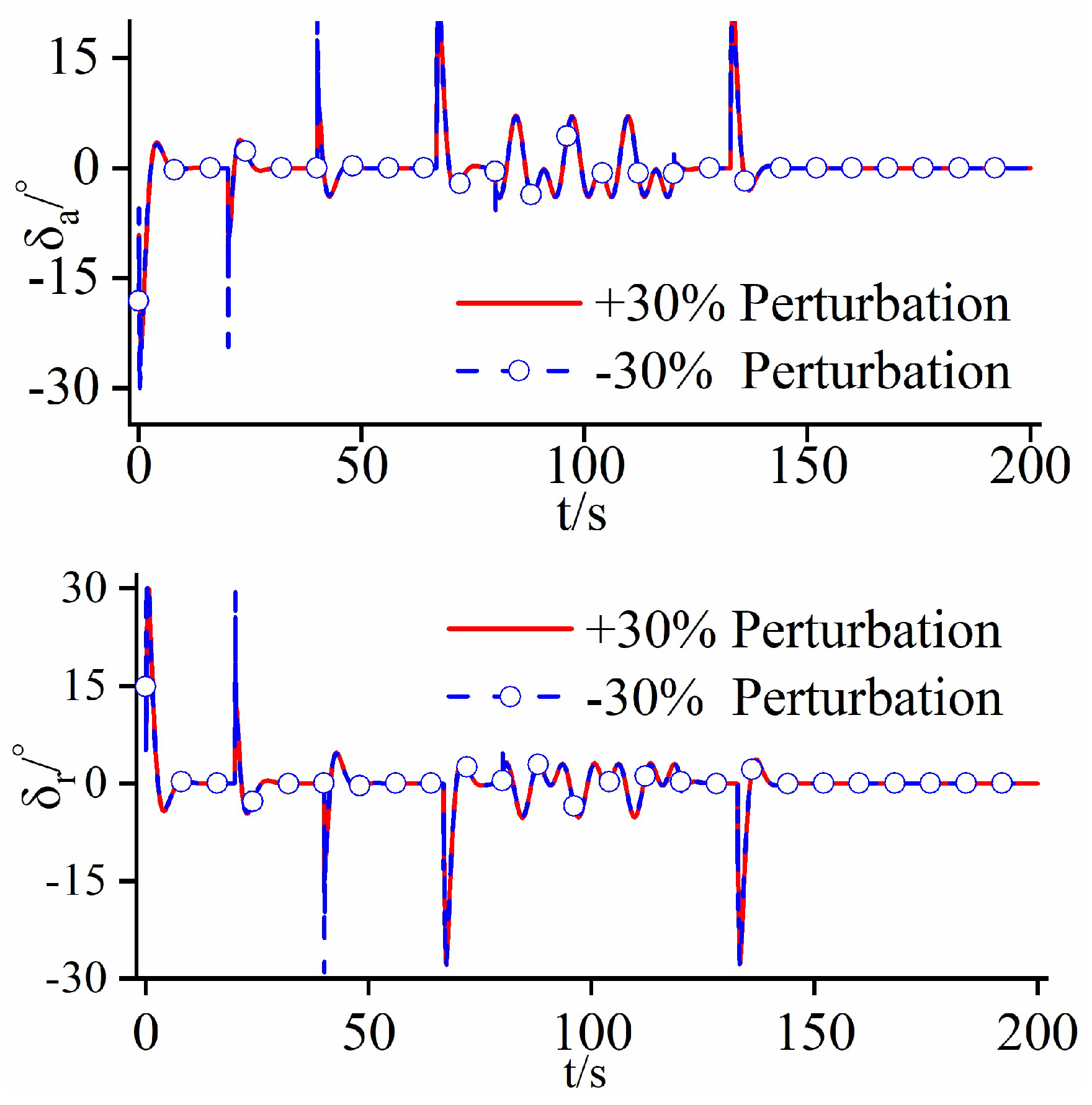
To demonstrate that the control design based on the proposed approach does not rely on precise model information, numerical studies with perturbation analysis were conducted, where model parameters b p a , b p r , b r a , and b r r varied by 30% and −30% perturbations in Equation (9). Moreover, comparisons between the perturbed and the unperturbed scenarios are made to validate the effectiveness of the proposed approach.
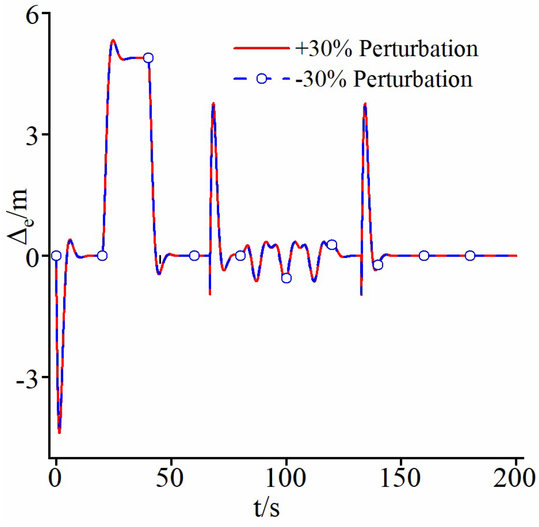
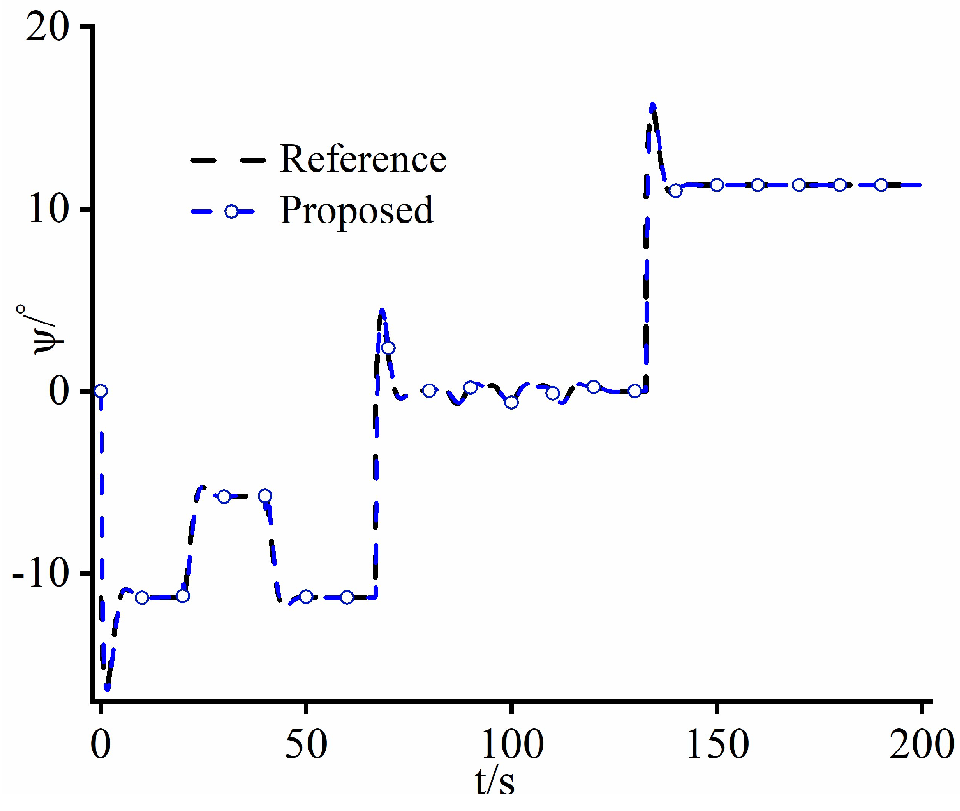
From Figure 11 and Figure 12, it can be observed that, under d r during 80–120 s, the UAV has quite small PF errors using the proposed control approach whether perturbations of the important model parameters exist or not, achieving effective control. It can be seen from Figure 12 that the errors between the two perturbation scenarios are quite similar, which indicates that even though the precise model information is not used, the proposed control approach can still achieve high PF accuracy. This is primarily attributed to the use of LESO in the yaw angle control system, enabling real-time online estimation and feedback compensation for uncertainties such as d r , disturbances, and nonlinear characteristics. Therefore, even though significant perturbations of the model parameters exist, the proposed approach can effectively implement precise cancelation to enhance the robustness of the closed-loop system, as shown in Figure 13 and Figure 14. In addition, even if there are estimation errors in the yaw angle system, the predictive function in the proposed approach can further enhance the robustness of the system and minimize the impacts from the estimation errors.
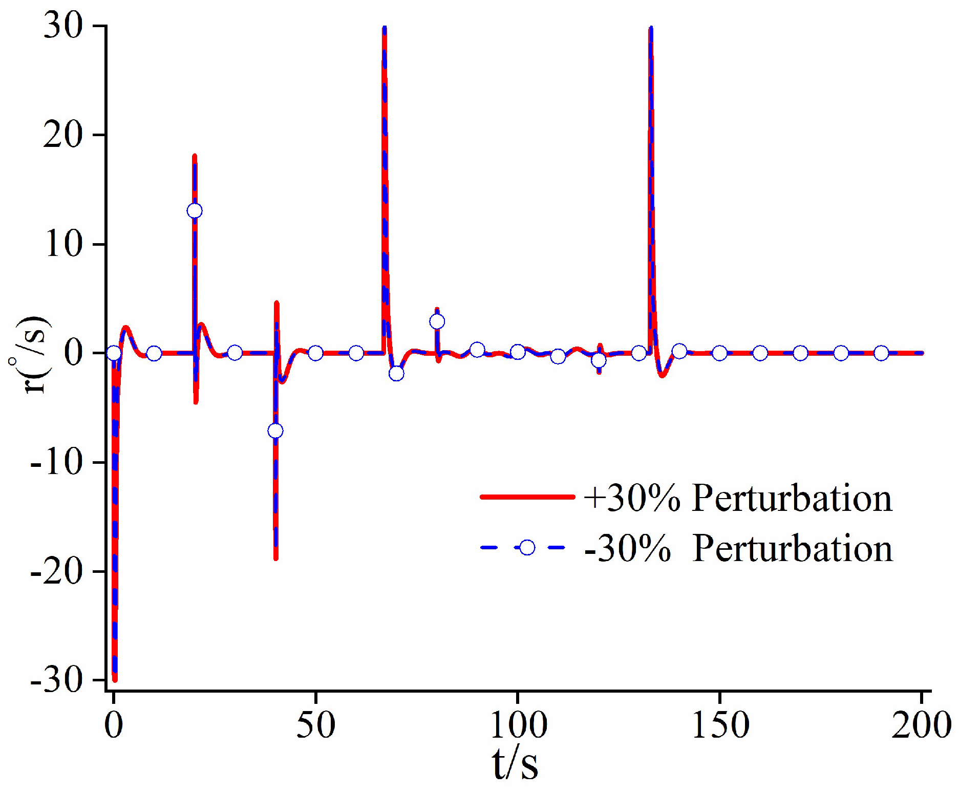
From Figure 15, Figure 16 and Figure 17, it can be seen that the proposed approach has quite small fluctuations in yaw angle under perturbations of +30%, −30%, and 0, which means that the aircraft has good stability. This fundamental achievement stems from the aforementioned disturbance handling mechanism which is capable of precise disturbance estimation and feedback compensation for enhancing the closed-loop system’s robustness against disturbances. Consequently, the vibrations in control inputs δ a and δ r are minimized, leading to reduced fluctuations in angular rates, as shown in Figure 17 and Figure 18. Furthermore, as shown in Figure 18, the control approach with the predictive function can improve the robustness of the closed-loop system and achieve softening of the control inputs, resulting in smaller fluctuations in the control surfaces.

5. Conclusions

This study has proposed an LESO-robustified straight-line PF control system for FWUAVs when uncertainties are encountered. Using only a small amount of rough dynamic model information, the command yaw angle can be obtained analytically from the distance between the gravitational center of the UAV and the prescribed straight-line path, the orientation of the prescribed straight-line path, the flow angles, and the current yaw angle.
For the yaw angle control, despite the presence of factors such as nonlinearities, couplings, and gusts affecting UAV flight performance, the LESO has been employed for accurate estimation and feedback compensation of all uncertainties. This significantly enhances PF accuracy and aircraft stability. Compared with the conventional NDI method, the approach proposed exhibits smaller PF errors and higher precision in the presence of uncertainties, which in turn ensure superior stability of the aircraft. Additionally, the integration of predictive capabilities can soften control inputs, which can further refine the PF accuracy of the closed-loop system.
Furthermore, due to the existence of the LESO, the proposed approach allows precise estimation and disturbance compensation for perturbations and uncertainty terms, resulting in minimal PF errors even when model parameters fluctuate within ±30%. This indicates that the proposed control method does not require precise model information and can still achieve high PF accuracy and strong closed-loop robustness.

Author Contributions

Conceptualization, M.T.; Methodology, W.Q.; Software, W.Q.; Validation, W.Q.; Formal analysis, W.Q.; Resources, M.T.; Data curation, X.L.; Writing – original draft, W.Q.; Visualization, X.L.; Supervision, Q.W. and W.S. All authors have read and agreed to the published version of the manuscript.

Funding

This research received no external funding.

Data Availability Statement

The supporting information is shared and available online by visiting https://github.com/maggie-nal/english-data-1.git.

Conflicts of Interest

The authors declare no conflict of interest.

Appendix A

First, the stability of the LESO is proven.
Formula (10) is re-written as follows:
X 1 = X 2 X 2 = X 3 + G X U X 3 = W t
Denote E 2 = Z 2 X 2 and E 3 = Z 3 F X . Then, subtracting Formula (A1) from (11) yields
E 1 = E 2 β 1 E 1 E 2 = E 3 β 2 E 1 E 3 = β 3 E 1 W t
Denote E = E 1 T , E 2 T , E 3 T T . By recalling Formula (12), Formula (A2) can be written in the following compact form:
E 1 = E 2 β 1 E 1 E 2 = E 3 β 2 E 1 E 3 = β 3 E 1 W t E = 3 ω 0 I I O 3 ω 0 2 I O I ω 0 3 I O O A E E O O I W t
where I and O are identity and zero matrices with relative degree, respectively.
It is easy to verify that the matrix A E is Horwitz. Thus, estimation errors E i and i = 1 , 2 , 3 are bounded.
Second, the stability of the closed-loop system is proven.
Denote ε = X 1 Y d . Then, bringing the control law (16) into the system plant model (10) and considering the estimation error E 3 , the closed-loop system is transformed into
ε + τ ε + ε = E 3
It is obvious that the differential equation of the tracking error ε has eigenvalues with negative real parts. Thus, the proof of the stability of the closed-loop system has been accomplished.

References

  1. Nelson, R.C. Flight Stability and Automatic Control, 1st ed.; McGraw-Hill Book Company Press: New York, NY, USA, 1989; pp. 96–130. [Google Scholar]
  2. Yintao, Z.; Youmin, Z.; Zhixiang, L.; Ziquan, Y.; Yaohong, Q. Line-of-Sight Path Following Control on UAV with Sideslip Estimation and Compensation. In Proceedings of the 37th Chinese Control Conference (CCC), Wuhan, China, 25–27 July 2018; pp. 4711–4716. [Google Scholar]
  3. Lu, L.; Dan, W.; Peng, Z. ESO-Based Line-of-Sight Guidance Law for Path Following of Underactuated Marine Surface Vehicles with Exact Sideslip Compensation. IEEE J. Ocean. Eng. 2017, 42, 477–487. [Google Scholar] [CrossRef]
  4. Ambrosino, G.; Ariola, M.; Ciniglio, U.; Corraro, F.; de Lellis, E.; Pironti, A. Path generation and tracking in 3-D for UAVs. IEEE Trans. Control Syst. Technol. 2009, 17, 980–988. [Google Scholar] [CrossRef]
  5. Tan, G.Y.; Luo, H.B.; Liao, F.; Wang, X.H.; Ji, H.B. Cooperative Strategy for Aircraft Defense Line-of-Sight Guidance in Three-Dimensional Space. In Proceedings of the 2022 41st Chinese Control Conference (CCC), Hefei, China, 25–27 July 2022; pp. 3398–3403. [Google Scholar]
  6. Balhance, N.; Martin, W.; Tal, S. Cooperative guidance law for intrasalvo tracking. J. Guid. Control Dyn. 2017, 40, 1441–1456. [Google Scholar] [CrossRef]
  7. Gu, J.C.; Ding, G.R.; Xu, Y.T.; Wang, H.C.; Wu, Q.H. Proactive optimization of transmission power and 3D trajectory in UAV-assisted relay systems with mobile ground users. Chin. J. Aeronaut. 2021, 34, 129–144. [Google Scholar] [CrossRef]
  8. Wilhelm, J.P.; Clem, G. Vector Field UAV Guidance for Path Following and Obstacle Avoidance with Minimal Deviation. J. Guid. Control Dyn. 2019, 42, 1848–1856. [Google Scholar] [CrossRef]
  9. Fari, S.; Wang, X.; Roy, S.; Baldi, S. Addressing Unmodeled Path-Following Dynamics via Adaptive Vector Field A UAV Test Case. IEEE Trans. Aerosp. Electron. Syst. 2020, 56, 1613–1622. [Google Scholar] [CrossRef]
  10. Nelson, D.R.; Barber, D.B.; McLain, T.W.; Beard, R.W. Vector field path following for miniature air vehicles. IEEE Trans. Robot. 2007, 23, 519–529. [Google Scholar] [CrossRef]
  11. Stephen, G. Vector Field Approach for Curved Path Following for Miniature Aerial Vehicles. In Proceedings of the AIAA Guidance, Navigation, and Control Conference and Exhibit, Keystone, CO, USA, 21–24 August 2006; pp. 1–15. [Google Scholar]
  12. Wilhelm, J.; Clem, G.; Casbeer, D.; Gerlach, A. Circumnavigation and obstacle avoidance guidance for UAVs using Gradient Vector Fields. In Proceedings of the AIAA Sci tech 2019 Forum, San Diego, CA, USA, 7–11 January 2019; pp. 1–15. [Google Scholar]
  13. Nelson, D.R.; Blake Barber, D.; McLain, T.W.; Beard, R.W. Vector Field Path Following for Small Unmanned Air Vehicles. In Proceedings of the 2006 American Control Conference, Minneapolis, MN, USA, 14–16 June 2006; pp. 5788–5794. [Google Scholar]
  14. Chen, Q.; Wang, X.G.; Yang, J.; Wang, Z.Y. Trajectory-following guidance based on a virtual target and an angle constraint. Aerosp. Sci. Technol. 2019, 87, 448–458. [Google Scholar] [CrossRef]
  15. Rucco, A.; Aguiar, A.; Hauser, J. Trajectory optimization for constrained UAVs: A virtual target vehicle approach. In Proceedings of the 2015 International Conference on Unmanned Aircraft Systems (ICUAS), Denver, CO, USA, 9–12 June 2015; pp. 236–245. [Google Scholar]
  16. Cai, Z.H.; Wang, L.H.; Zhao, J.; Wu, K.; Wang, Y.X. Virtual target guidance-based distributed model 4 predictive control for formation control of multiple 5 UAVs. Chin. J. Aeronaut. 2020, 33, 1037–1056. [Google Scholar] [CrossRef]
  17. Chen, H.; Wang, X.K.; Shen, L.C.; Cong, Y.R. Formation flight of fixed-wing UAV swarms: A 4 group-based hierarchical approach. Chin. J. Aeronaut. 2021, 34, 504–515. [Google Scholar] [CrossRef]
  18. Park, S.; Deyst, J.; How, J.P. Performance and Lyapunov stability and of a nonlinear path following guidance method. J. Guid. Control Dyn. 2007, 30, 1718–1728. [Google Scholar] [CrossRef]
  19. Tan, Y.Y.; Tang, W.X. Guidance Strategy for UAV Tracking Target Based on Reference Point Guidance Method. J. Northwestern Polytech. Univ. 2020, 38, 176–182. [Google Scholar] [CrossRef]
  20. Zhou, W.H.; Li, J.; Liu, Z.H.; Shen, L.C. Improving multi-target cooperative tracking guidance for UAV swarms using multi-agent reinforcement learning. Chin. J. Aeronaut. 2022, 35, 100–112. [Google Scholar] [CrossRef]
  21. Yin, H.; Li, D.G.; Wang, Y.; Li, X.P. Adaptive Dynamic Occupancy Guidance for Air Combat of UAV. Unmanned Syst. 2024, 12, 29–46. [Google Scholar] [CrossRef]
  22. Modali, S.; Ghosh, S. Terminal-Angle-Constrained Guidance based on Sliding Mode Control for UAV Soft Landing on Ground Vehicles. Electr. Eng. Syst. Sci. 2020, 2009, 1–14. [Google Scholar]
  23. Mao, Y.H.; Chen, Q.Y.; Hou, Z.X.; Zheng, G. An Improved Nonlinear Guidance Law for Unmanned Aerial Vehicles Path Following. In Proceedings of the 2015 34th Chinese Control Conference (CCC), Hangzhou, China, 28–30 July 2015; pp. 5271–5276. [Google Scholar]
  24. Kaminer, I.; Pascoal, A.; Xargay, E.; Hovakimyan, N.; Cao, C.Y.; Dobrokhodov, V. Path following for unmanned aerial vehicles using L1 adaptive augmentation of commercial autopilots. J. Guid. Control Dyn. 2010, 33, 550–564. [Google Scholar] [CrossRef]
  25. Chengyu, C.; Naira, H. Design and Analysis of a Novel L1 Adaptive Control Architecture With Guaranteed Transient Performance. IEEE Trans. Autom. Control 2008, 53, 586–591. [Google Scholar]
  26. Liu, C.J.; McAree, O.; Chen, W.H. Path-following control for small fixed-wing unmanned aerial vehicles under wind disturbances. Int. J. Robust Nonlinear Control 2013, 23, 1682–1698. [Google Scholar] [CrossRef]
  27. Beard, R.W.; Ferrin, J.; Humpherys, J. Fixed wing UAV path following in wind with input constraints. IEEE Trans. Control Syst. Technol. 2014, 22, 2103–2117. [Google Scholar] [CrossRef]
  28. Zhao, S.L.; Wang, X.K.; Zhang, D.B.; Shen, L.C. Curved Path Following Control for Fixed-wing Unmanned Aerial Vehicles with Control Constraint. J. Intell. Robot. Syst. 2017, 89, 107–119. [Google Scholar] [CrossRef]
  29. Gavilan, F.; Vazquez, R.; Camacho, E.F. An iterative model predictive control algorithm for UAV guidance. IEEE Trans. Aerosp. Electron. Syst. 2015, 51, 2406–2419. [Google Scholar] [CrossRef]
  30. Alberto, B.; Claudio, R. Decentralized linear time-varying model predictive control of a formation of unmanned aerial vehicles. In Proceedings of the 2011 50th IEEE Conference on Decision and Control and European Control Conference, Orlando, FL, USA, 12–15 December; pp. 7488–7493.
  31. Yang, J.; Liu, C.J.; Coombes, M.; Yan, Y.D.; Chen, W.H. Optimal path following for small fixed-wing UAVs under wind disturbances. IEEE Trans. Control Syst. Technol. 2020, 29, 996–1008. [Google Scholar] [CrossRef]
  32. Yang, J.; Liu, C.; Zuo, Z.; Chen, W.-H. A simple optimal planer path following algorithm for unmanned aerial vehicles. In Proceedings of the 2018 European Control Conference (ECC), Limassol, Cyprus, 12–15 June 2018; pp. 1809–1814. [Google Scholar]
  33. Kwang, Y.; Yeonsik, K.; Salah, S. Adaptive nonlinear model predictive path-following control for a fixed-wing unmanned aerial vehicle. Int. J. Control Autom. Syst. 2013, 11, 65–74. [Google Scholar]
  34. Yeonsik, K.; Karl, J.H. Linear Tracking for a Fixed-Wing UAV Using Nonlinear Model Predictive Control. IEEE Trans. Control Syst. Technol. 2009, 17, 1202–1210. [Google Scholar] [CrossRef]
  35. Kothari, M.; Postlethwaite, I.; Gu, D.W. A suboptimal path planning algorithm using rapidly-exploring random trees. Int. J. Aerosp. Innov. 2010, 2, 93–104. [Google Scholar]
  36. Rucco, A.; Aguiar, A.P.; Pereira, F.L.; de Sousa, J.B. A predictive path-following approach for fixed-wing unmanned aerial vehicles in presence of wind disturbances. In Proceedings of the Robot 2nd Iberian Robotics Conference, Lisbon, Portugal, 19–21 November 2015; pp. 623–634. [Google Scholar]
  37. Brezoescu, A.; Espinoza, T.; Castillo, P.; Lozano, R. Adaptive trajectory following for a fixed-wing UAV in presence of crosswind. J. Intell. Robot. Syst. 2013, 69, 257–271. [Google Scholar] [CrossRef]
  38. Qi, W.; Li, Y.; Yaowei, W.; Wenan, Z. LESO-based position synchronization control for networked multi-axis servo systems with time-varying delay. IEEE/CAA J. Autom. Sin. 2020, 7, 1116–1123. [Google Scholar]
  39. Yang, Z.; Miao, C.; Sun, X. Model predictive current control for IPMSM drives with extended-state-observer-based sliding mode speed controller. IEEE Trans. Energy Convers. 2022, 38, 1471–1480. [Google Scholar] [CrossRef]
  40. Qin, Q.; Gao, G.; Zhong, J. Finite-time adaptive extended state observer-based dynamic sliding mode control for hybrid robots. IEEE Trans. Circuits Syst. II Express Briefs 2022, 69, 3784–3788. [Google Scholar] [CrossRef]
  41. Zuo, Y.; Chen, J.; Zhu, X.; Lee, C.H.T. Different active disturbance rejection controllers based on the same order GPI observer. IEEE Trans. Ind. Electron. 2021, 69, 10969–10983. [Google Scholar] [CrossRef]
  42. Beard, R.W.; Mclain, T.W. Small Unmanned Airplane: Theory and Practice, 1st ed.; Princeton University Press: Princeton, NJ, USA, 2012; pp. 45–56. [Google Scholar]
  43. She, J.; Miyamoto, K.; Han, Q.L.; Wu, M.; Hashimoto, H.; Wang, Q.G. Generalized-extended-state-observer and equivalent-input-disturbance methods for active disturbance rejection: Deep observation and comparison. IEEE/CAA J. Autom. Sin. 2023, 10, 957–968. [Google Scholar] [CrossRef]
  44. Nie, K.; Qiao, Q.; Deng, J.Q.; Ren, W.; Mao, Y. Model-assisted Linear Extended State Observer for Opto-Electronic Stabilized Platform. In Proceedings of the 34rd Youth Academic Annual Conference of Chinese Association of Automation (YAC), Jinzhou, China, 5 August 2019; pp. 370–374. [Google Scholar]
  45. Feng, Y.; Zhang, C.; Baek, S.; Rawashdeh, S.; Mohammadi, A. Autonomous landing of a UAV on a moving platform using model predictive control. Drones 2018, 2, 34. [Google Scholar] [CrossRef]
  46. Saccani, D.; Cecchin, L.; Fagiano, L. Multitrajectory Model Predictive Control for Safe UAV Navigation in an Unknown Environment. IEEE Trans. Control Syst. Technol. 2022, 31, 1982–1997. [Google Scholar] [CrossRef]
  47. Wang, X.; Van Kampen, E.J.; Chu, Q.; Lu, P. Stability Analysis for Incremental Nonlinear Dynamic Inversion Control. J. Guid. Control Dyn. 2019, 42, 1–14. [Google Scholar] [CrossRef]
  48. Chen, W. Nonlinear disturbance observer-enhanced dynamic inversion control of missiles. J. Guid. Control Dyn. 2003, 26, 161–166. [Google Scholar] [CrossRef]
  49. Askari, A.; Mortazavi, M.; Talebi, H.A. UAV formation control via the virtual structure approach. J. Aerosp. Eng. 2015, 28, 1–34. [Google Scholar] [CrossRef]
  50. Ji, X.; Wei, X.; Wang, A. A Novel Control Method for Unmanned Agricultural Tractors: Composite Back-stepping Sliding Mode Path Tracking. Inf. Technol. Control 2023, 52, 515–528. [Google Scholar] [CrossRef]
  51. Yang, Z.; Jia, J.; Sun, X.; Xu, T. An enhanced linear ADRC strategy for a bearingless induction motor. IEEE Trans. Transp. Electrif. 2021, 8, 1255–1266. [Google Scholar] [CrossRef]
  52. Qiu, X.; Zhang, M.; Jing, W.; Gao, C. Dynamics and adaptive sliding mode control of a mass-actuated fixed-wing UAV. Int. J. Aeronaut. Space Sci. 2021, 22, 886–897. [Google Scholar] [CrossRef]
Figure 1. Straight-line path following.
Aerospace 11 00902 g001
Figure 2. Schematic of the control scheme.
Aerospace 11 00902 g002
Figure 3. Path-following results.
Aerospace 11 00902 g003
Figure 4. Path-following errors.
Aerospace 11 00902 g004
Figure 5. Uncertainty estimation results.
Aerospace 11 00902 g005
Figure 6. Yaw angles: proposed approach.
Aerospace 11 00902 g006
Figure 7. Yaw angles: the NDI approach.
Aerospace 11 00902 g007
Figure 8. Yaw angles: the SMC approach.
Aerospace 11 00902 g008
Figure 9. Yaw rates.
Aerospace 11 00902 g009
Figure 10. Control laws.
Aerospace 11 00902 g010
Figure 11. Path-following results.
Aerospace 11 00902 g011
Figure 12. Path-following errors.
Aerospace 11 00902 g012
Figure 13. LESO estimation results: +30% perturbation.
Aerospace 11 00902 g013
Figure 14. LESO estimation results: −30% perturbation.
Aerospace 11 00902 g014
Figure 15. Yaw angles: +30%.
Aerospace 11 00902 g015
Figure 16. Yaw angles: −30%.
Aerospace 11 00902 g016
Figure 17. Yaw rates.
Aerospace 11 00902 g017
Figure 18. Control laws.
Aerospace 11 00902 g018
Table 1. Aerodynamic coefficients for the FWUAV [42].
ParameterValueParameterValue
I x 0.8244 kg·m2 I z 1.759 kg·m2
S0.55 m2b2.8956 m
C l 0 0 C n 0 0
C l β −0.12 C n β 0.25
C l r 0.14 C n r −0.35
C l δ a 0.08 C n δ a 0.06
C l δ r 0.105 C n δ r −0.032
Disclaimer/Publisher’s Note: The statements, opinions and data contained in all publications are solely those of the individual author(s) and contributor(s) and not of MDPI and/or the editor(s). MDPI and/or the editor(s) disclaim responsibility for any injury to people or property resulting from any ideas, methods, instructions or products referred to in the content.