Article

Study on the Dynamic Crushing Behaviors of Hourglass Honeycomb Sandwich Panels

1
School of Civil Engineering and Transportation, Northeast Forestry University, Harbin 150040, China
2
National Innovation Institute of Defense Technology, Academy of Military Science, Beijing 100071, China
*
Authors to whom correspondence should be addressed.
Aerospace 2024, 11(11), 881; https://doi.org/10.3390/aerospace11110881
Submission received: 9 August 2024 / Revised: 20 October 2024 / Accepted: 21 October 2024 / Published: 25 October 2024

Abstract

:
In response to the problem of enclosed internal spaces in existing honeycomb sandwich panels, the concept of an hourglass honeycomb sandwich panel model is proposed for the first time, which provides a breakthrough approach for achieving the multifunctional integration of honeycomb sandwich panels. Numerical simulation methods are employed to investigate the dynamic performance of the hourglass honeycomb sandwich panels. The focus is on discussing the influences of the geometric parameters on the deformation mode, dynamic response, load uniformity, and energy absorption capacity of the hourglass honeycomb sandwich panel under different impact velocity conditions. The research results indicate that under low-velocity-impact conditions, the influence of the geometric parameters is predominant. In contrast, under high-velocity-impact conditions, the influence of the impact velocity conditions is predominant. Hourglass honeycomb sandwich panels with low density, a large inclination angle of the honeycomb wall, and small contact distances between the hourglass honeycomb cell and the panel have excellent load uniformity, and the distances between the contact points of the hourglass honeycomb cell and the panel have a great influence on the energy absorption capacity of the sandwich panels. This study provides a theoretical basis for the application of honeycombs in aerospace and other engineering areas.

1. Introduction

Honeycombs are widely used in various high-tech fields such as aerospace, civil engineering, mechanical engineering, and bioengineering owing to their light weight, high strength, and excellent energy absorption performance during dynamic crushing [1,2,3,4,5]. With the continuous promotion of resource conservation and sustainable development, the engineering demand and application scope of honeycombs are constantly expanding. Honeycombs can be obtained by the regular arrangement of units of a certain configuration. The configuration of the units was initially derived from the honeycomb configuration in nature and has been developed into various new configurations through long-term research. As energy-absorbing materials, load uniformity and energy-absorbing properties have always been essential evaluation indicators for assessing the dynamic properties of honeycombs [6,7,8]. Based on the load uniformity and energy absorption performance, conducting research on new configuration designs and geometric parameters of honeycombs is an effective way to improve the resistance of protected structures to dynamic crushing damage [9,10,11].
Regarding the research on honeycombs, domestic and foreign scholars have used methods such as theoretical analysis, numerical simulation, and experimental testing to deeply explore the macroscopic dynamic responses of honeycombs, from the design of new configurations to the influences of geometric parameters and impact conditions [12,13,14,15,16,17]. In terms of the micro-topological configuration design, existing regular honeycomb configurations include hexagonal, triangular, square, circular, arrow-shaped, star-shaped, horseshoe-shaped, chiral bodies, etc. [18,19,20,21,22]. Based on the biomimetic design principles, convex configurations can be changed to concave configurations and flat honeycomb walls can be changed to curved ones [23]. The results show that the relative density has an important influence on the mechanical behavior and energy absorption performance of honeycombs. By comparing the mechanical performance of honeycombs with different micro-topological configurations, it is helpful to explore the mechanism of the influence of the topological configuration of honeycombs.
In terms of the influence mechanism of geometric parameters and impact conditions, in order to further improve the mechanical performance and energy absorption capacity of honeycombs, scholars have established corresponding honeycombs through gradient design, hierarchical design, disordered design, Poisson’s ratio design, and composite design, and have studied their mechanical responses [24,25,26]. By changing the relative density of honeycombs, establishing gradient honeycombs, and placing high-density layers at the impact end and the low-density layers at the distal end, the gradient design can effectively improve the energy absorption efficiency of honeycombs and reduce the strength of the forces acting on the output end [27,28,29,30]. By changing the characteristic parameters of the micro-topological configurations of honeycombs, unconventional zero/negative-stiffness honeycombs and zero/negative-Poisson-ratio honeycombs can be established [31,32,33,34]. In addition, by changing the micro-topological configurations and geometric parameters of primary or secondary honeycombs, the stiffness and Poisson’s ratio of honeycombs can be designed, special Poisson-ratio combinations in multiple directions can be achieved, and new high-stiffness and stable three-dimensional secondary-layered honeycombs can be established. The influence of the impact loading conditions includes the influence of the loading rate and loading direction. The action of stress waves during dynamic crushing is significant, and the impact loading rate affects the deformation mode of honeycombs. The change in the deformation mode will lead to the change in the initiation mode of the plastic deformation of the honeycombs, which further changes the energy absorption process. Honeycombs are spatially anisotropic materials, and various micro-topological configurations exhibit different response characteristics to different impact loading directions. Papka et al. [35,36] and Chuang et al. [37,38] studied the deformation modes and energy absorption characteristics of honeycombs under orthogonal biaxial compression conditions, respectively. The research results show that finite element models can accurately capture the essential features observed and measured in the experiments and have good accuracy for the prediction of energy absorption capacity. In addition, many cell-collapse modes observed in the experiments were reproduced in the simulations.
Honeycomb sandwich panels have better uniformity, stronger designability, richer micro-topological configurations, and simpler preparation processes than lattice sandwich panels. However, the internal space of the honeycombs is not connected, which does not help immensely in integrated designs of multifunction systems, such as wiring installation, embedded energy-absorbing materials or fireproof materials, and liquid storage [39]. Therefore, based on the circular honeycomb, this study designed a new topological configuration of an hourglass honeycomb and established honeycombs with interconnected and intercommunicating spaces. In addition, one of the major performance issues of sandwich panels is their foreign object dynamic performance. This can be a result of dropped tools, hail, and bird strikes. Impacts can give rise to partial and full penetration [40]. This study addressed the drop weight impact scenario and used numerical simulation methods to study the influences of impact velocity and geometric parameters on the deformation mode, dynamic response, load uniformity, and energy absorption performance of the hourglass honeycomb sandwich panels. The research in this study helps improve the dynamic performance and functional integration capability of honeycomb sandwich panels and promotes the scope of honeycombs in practical engineering applications such as aerospace.

2. Computational Model

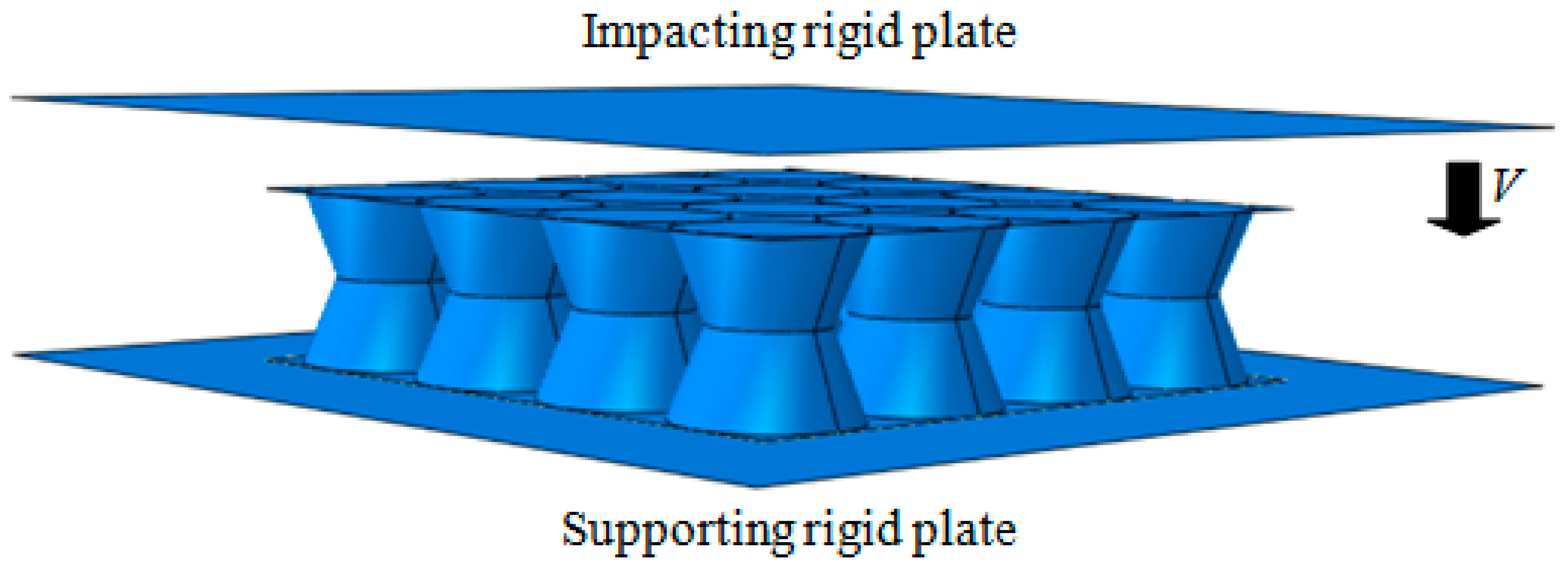
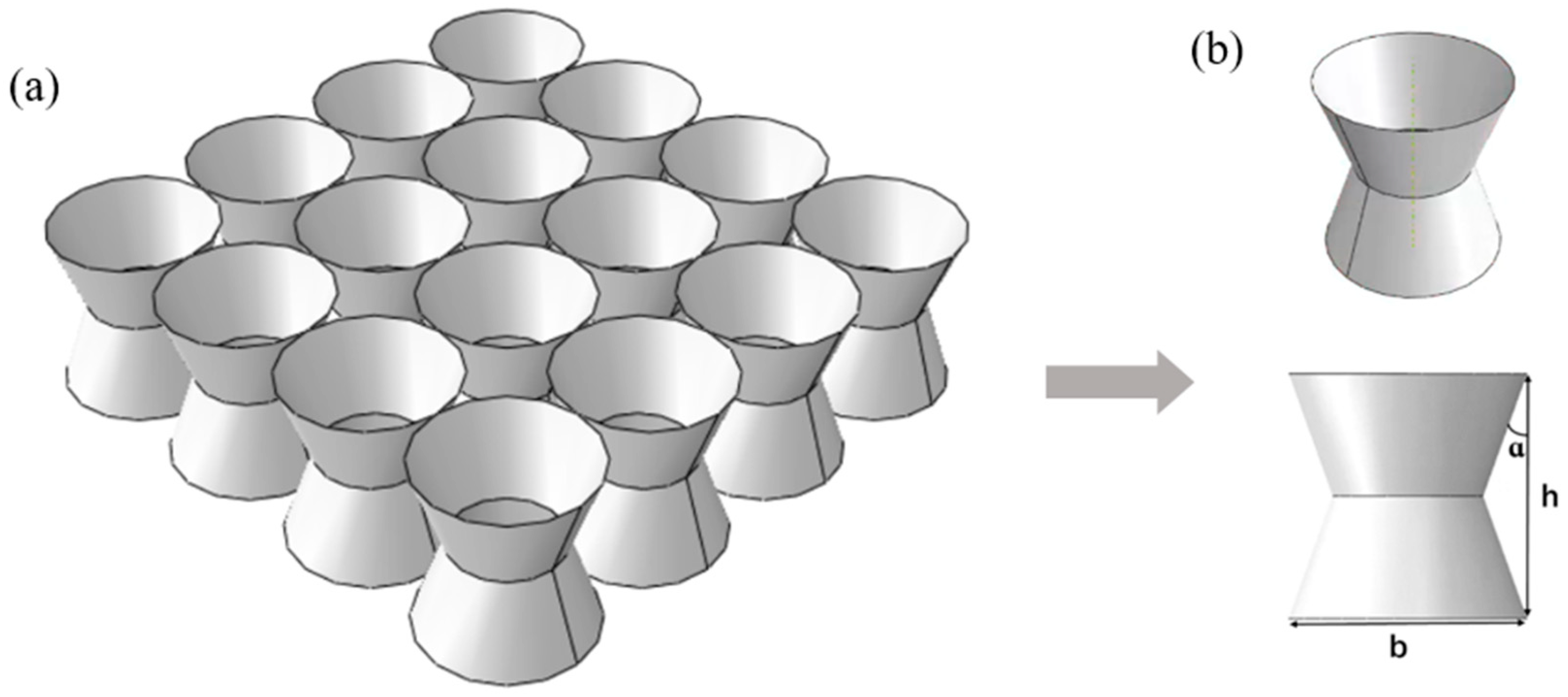
2.1. Finite Element Model

Honeycomb sandwich panels exhibit good energy absorption performance and strong designability. However, a closed internal unit space is not conducive to multifunctional integration. Therefore, based on the circular honeycombs, this study designed a new hourglass honeycomb configuration, established a model of an hourglass honeycomb sandwich panel, and studied the dynamic performance of panels under the same relative density conditions through numerical simulation methods. The computational model is shown in Figure 1. The computational model included three parts: the upper and lower rigid plates, the hourglass honeycomb, and the upper and lower solid panels with identical geometric dimensions. The hourglass honeycomb sandwich panel was formed by welding the hourglass honeycomb and solid panels together. The hourglass honeycomb was arranged as an array of hourglass cells in a plane, as shown in Figure 2. To fully demonstrate the influence of the geometric parameters on the dynamic performance of the hourglass honeycomb sandwich panel, nine types of hourglass honeycomb sandwich panels (denoted as H1, H2, …, H9) are discussed, including multilayer hourglass honeycomb sandwich panels, that is, sandwich panels composed of multiple layers of hourglass honeycombs with identical geometric dimensions. For comparative analysis, this study also provided circular honeycomb sandwich panels (H0) as reference objects and analyzed their dynamic performance.
Based on the computational model shown in Figure 1, the dynamic response characteristics of the hourglass honeycomb sandwich panels were investigated using the finite element code ABAQUS2020. The planar graph of the hourglass cell was drawn by ABAQUS2020/CAE, and the hourglass honeycomb cell was established by rotating the graph. The hourglass honeycomb was established through arranging the hourglass cell, and the sandwich panel specimen was established by welding the hourglass honeycomb with the upper and lower panels. The specimen was placed on a fixed, rigid plate at the bottom, without constraints around it. A constant velocity was applied to the top rigid plate, which crushed the specimen. The specimen was damaged by the rigid plate after undergoing irreversible plastic deformation, thus ensuring that the protected object damages were minimal [41]. To ensure computational accuracy, the specimen was discretized using S4R shell elements (4-node, reduced integration elements) with five integration points along the shell thickness direction. During the dynamic crushing process, the coefficient of friction between the rigid plate and the specimen was set to 0.2. The matrix material of the hourglass honeycomb sandwich panel was referred from Ruan et al. [12,42] and was assumed to be elastic/perfectly plastic. For all models, the main material parameters were as follows: density, ρs = 2700 kg/m3; Young’s modulus, Es = 69 GPa; Poisson’s ratio, μ = 0.3; yield strength, σys = 76 MPa. Impact velocities of 2 m/s, 30 m/s, and 120 m/s were selected. Table 1 lists the geometric parameter values of the different types of hourglass honeycombs. Here, n represents the number of layers of the honeycomb core, α represents the inclination angle of the honeycomb walls, t represents the thickness of the honeycomb walls, h represents the height of the honeycomb unit cell, and b represents the maximum diameter of the honeycomb unit cell.

2.2. Relative Density

Relative density Δρ is an essential factor that influences the mechanical properties of honeycombs and can be calculated as
Δ ρ = ρ ρ s
where ρ and ρs represent the density of, respectively, honeycombs and the matrix material. The relative density of the circular honeycomb is
Δ ρ = π t c ( 2 R c t c ) 4 R c 2
where tc is the thickness of the circular honeycomb wall, and Rc is the radius of the circular honeycomb cell. The relative density of the hourglass honeycomb is
Δ ρ = π [ R h t h + ( R h 1 2 h tan ( α ) t h t h 2 ] 4 R h 2
where th is the thickness of the hourglass honeycomb wall, and Rh is the maximum radius of the hourglass honeycomb cell.

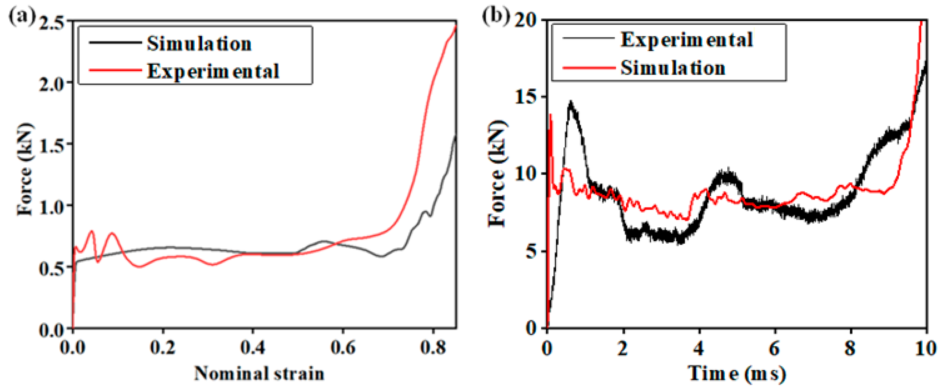
2.3. Validation of Finite Element Model

A comparative analysis was conducted with experimental results from previous studies to validate the reliability of the numerical simulation method in this study. Static and dynamic experimental results were both considered, and the experimental results were extracted from references [43] and [44], respectively. Compression tests were carried out by using a material testing machine with computer control and data acquisition systems. The testing was displacement-controlled with the top plate of the machine being moved vertically downward to compress the specimens. In this study, a calculation model was established based on the same material and geometric parameters of the specimen in the tests of the references, and the same loading conditions were set to the impact rigid plate. Figure 3 shows comparison curves of the sandwich panels under compressive loading. Here, the nominal strain ε is defined as
ε = δ / h
where δ represents the displacement of the impact rigid plate and h represents the initiation length of the honeycomb along the direction of dynamic crushing compression. The figure shows that the numerical simulation results of this study agree well with the experimental results of previous studies, which demonstrates that the numerical simulation method adopted in this study is reliable.

3. Results and Discussion

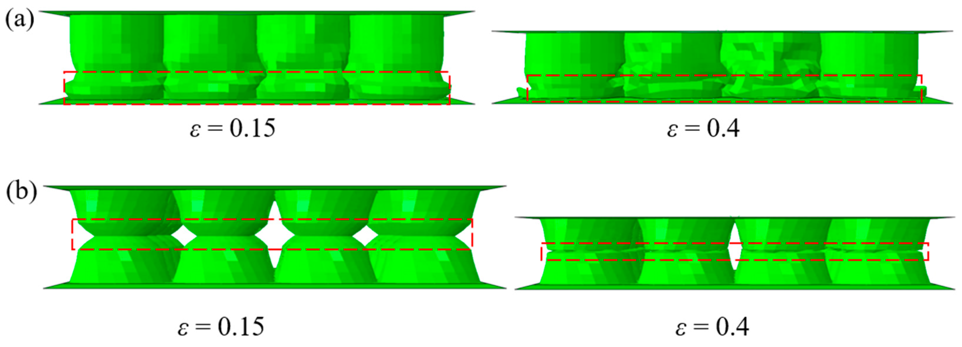
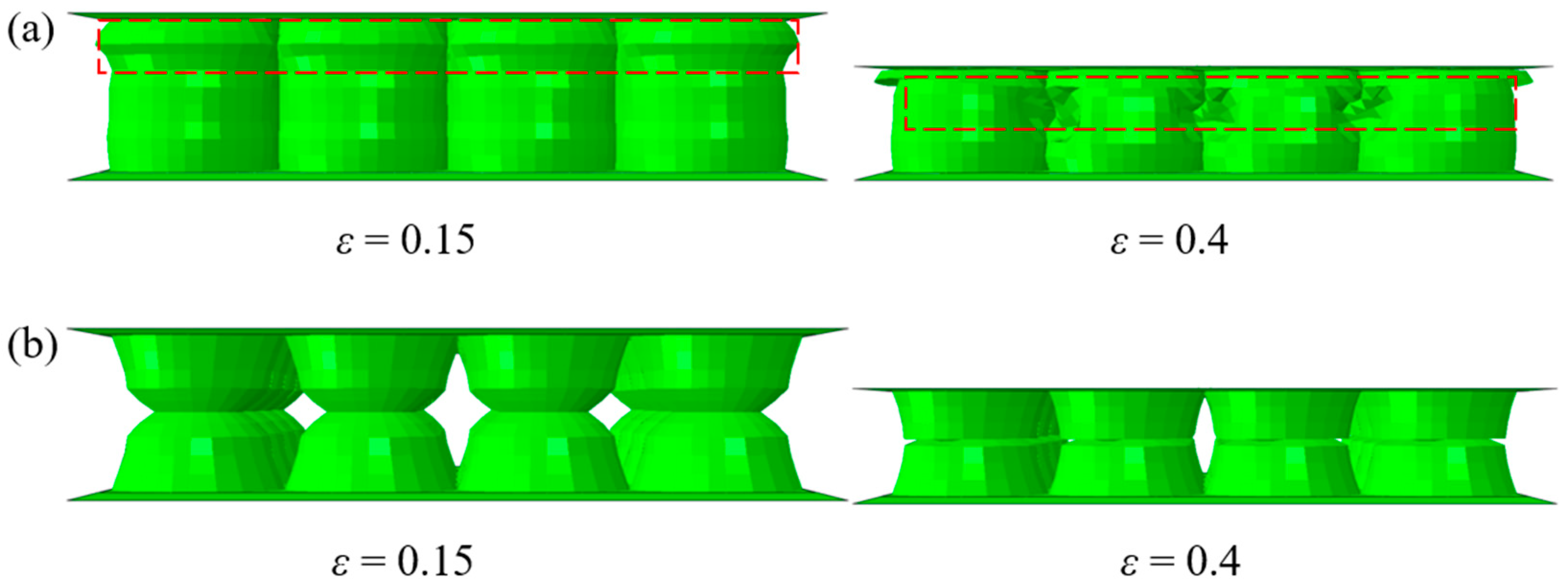
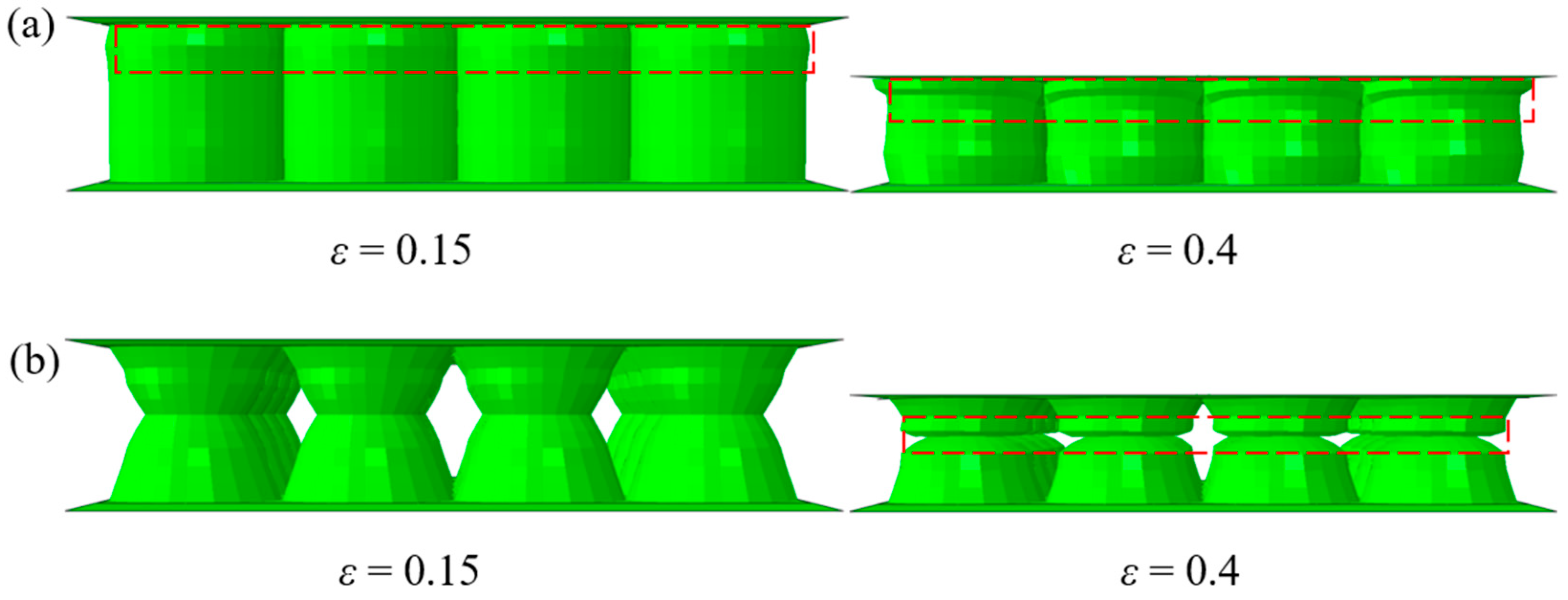
3.1. Deformation Modes

Both the micro-topological configuration of the honeycombs and the impact velocity conditions influence the deformation modes of the sandwich panel. Figure 4, Figure 5 and Figure 6 present the deformation patterns of the hourglass honeycomb sandwich panel under different impact velocity conditions at nominal strains of ε = 0.15 and ε = 0.4. Due to space limitations, only the H1-type hourglass honeycomb sandwich panel results are presented as representative deformation patterns. For comparative analysis, the figures also show the deformation results of the circular honeycomb sandwich panel (H0) simultaneously.
Figure 4 illustrates the deformation patterns of the honeycomb sandwich panels under low-velocity-impact conditions (v = 2 m/s). As shown in Figure 4a, the compressive deformation of the circular honeycomb sandwich panel first occurs near the bottom end and forms wrinkles, gradually leading to collapse (highlighted by the red dashed box). This is because under low-velocity-impact conditions, stress waves quickly propagate to the bottom end and enhance the contact force at the bottom end. This phenomenon is consistent with some observations from previous studies. In comparison, the compressive deformation and stress concentration region of the hourglass honeycomb sandwich panel first occurs in the middle section and forms wrinkles, gradually leading to collapse (highlighted by the red dashed box). This is because the circumference length of the middle section is smaller, requiring less energy for plastic deformation and the formation of plastic hinges, leading to rotational deformation of the hourglass honeycomb wall around the plastic hinges.
With the increase in impact velocity (v = 30 m/s), the deformation pattern of the circular honeycomb sandwich panel changes, as shown in Figure 5a. The circular honeycomb sandwich panel undergoes initiation compression deformation near the top of the impact rigid plate (highlighted by the red dashed box). This is because with the increase in impact velocity, the top of the circular honeycomb sandwich panel completes initiation compression deformation before stress waves propagate to the bottom end, gradually forming wrinkles until collapse. As the rigid plate continues to compress, the circular honeycomb sandwich panel undergoes uniform compression deformation and forms wrinkles at different positions along the direction of dynamic crushing (highlighted by the red dashed box). This is because with the progression of compression, stress waves are evenly distributed in the structure, leading to overall deformation and collapse. In comparison, the deformation pattern of the hourglass honeycomb sandwich panel changes minimally, as shown in Figure 5b. This indicates that the hourglass honeycomb sandwich panel exhibits stronger adaptability to the changes in impact velocity and can maintain a constant deformation pattern.
With the further increase in impact velocity (v = 120 m/s), Figure 6 illustrates the deformation patterns of the honeycomb sandwich panels under high-velocity-impact conditions. As shown in this figure, during the initiation compression stage, both the circular and hourglass honeycomb sandwich panels undergo changes in deformation patterns and exhibit similarities. Compression deformation starts from the top end near the impacting rigid plate, and the panels undergo layer-by-layer deformation and wrinkle formation until complete collapse (highlighted by the red dashed box). As the compression progresses, differences in the deformation patterns of the circular and hourglass honeycomb sandwich panels show differences. When the compression process approaches the midpoint, the middle section of the circular honeycomb sandwich panel shows no significant deformation, whereas the middle section of the hourglass honeycomb sandwich panel has already initiated deformation (highlighted by the red dashed box). This is because the middle section of the hourglass honeycomb panel is the boundary where the cross-section changes to the minimum cross-section.

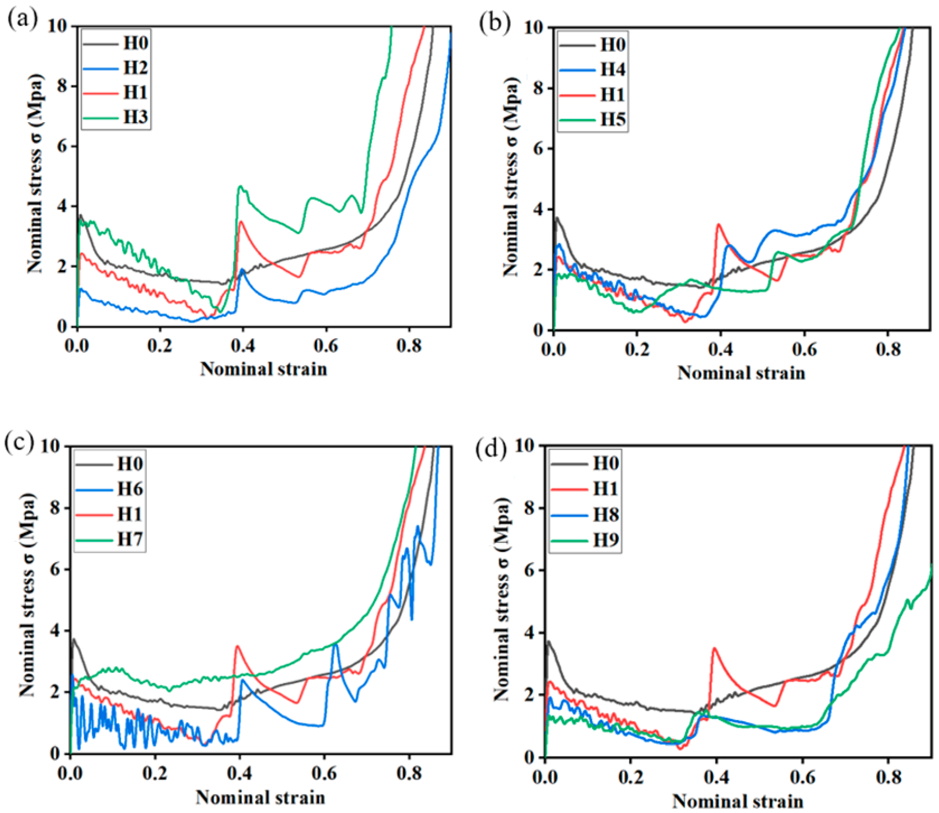
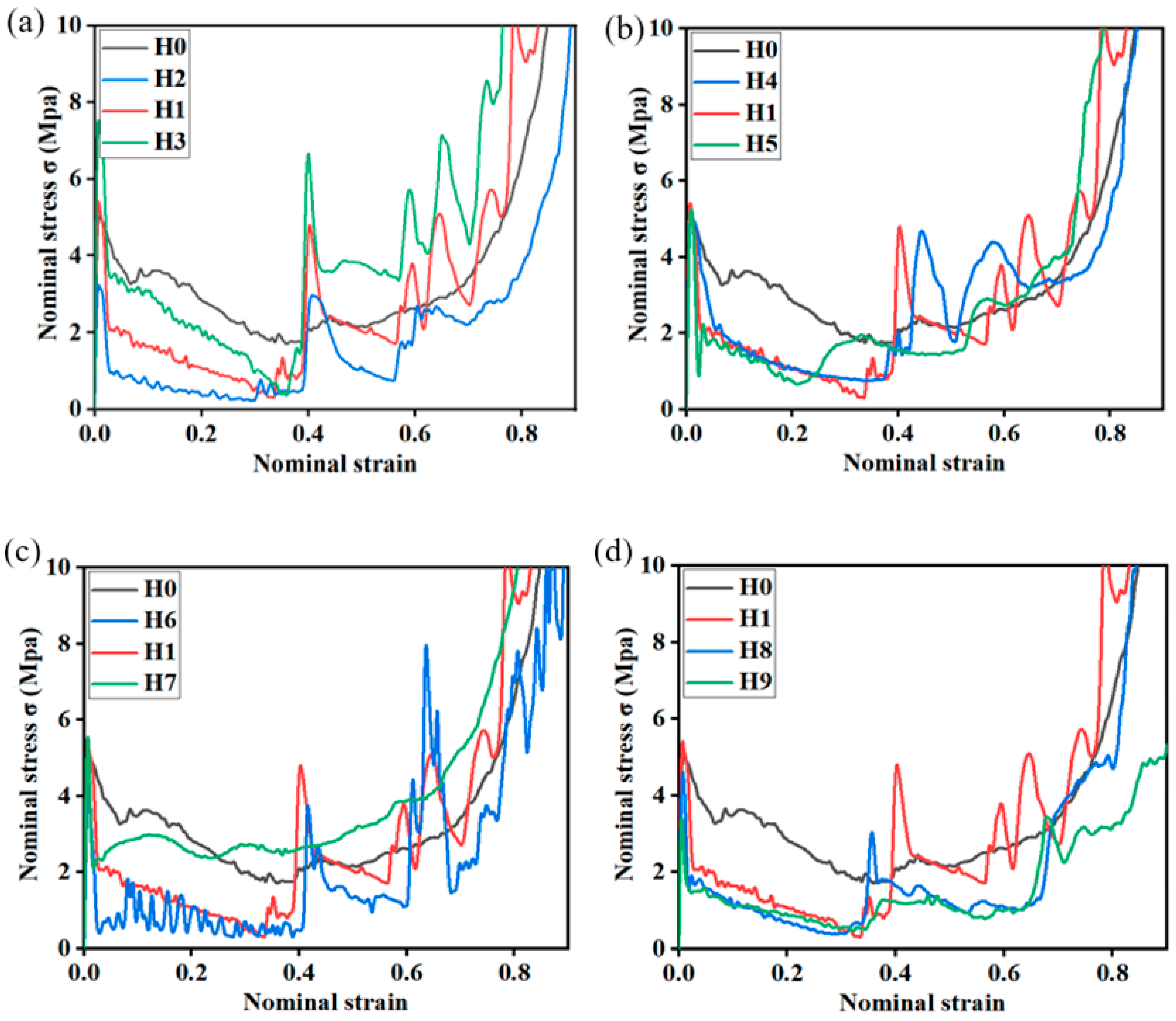
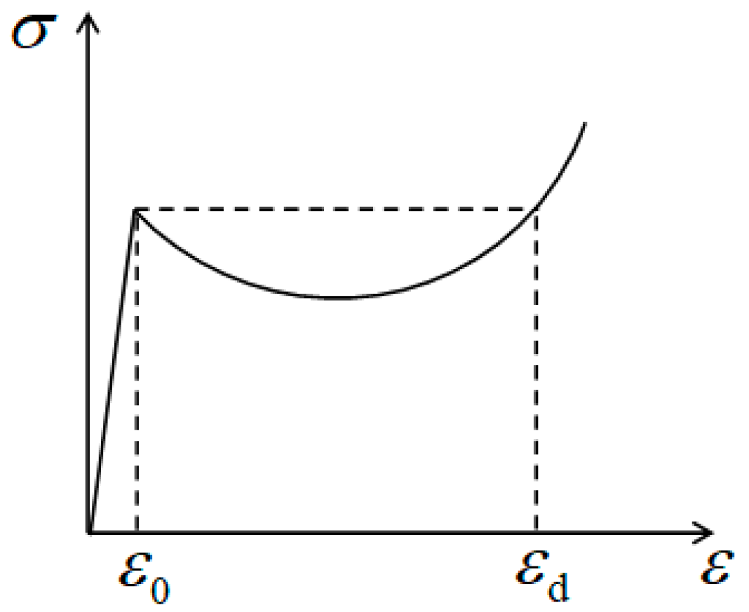
3.2. Nominal Stress–Strain Curve

Figure 7, Figure 8 and Figure 9 depict the numerical simulation results of the nominal stress–strain relationship of the hourglass honeycomb sandwich panel under varying velocity impact conditions. For comparative analysis, the computational results of the circular honeycomb sandwich panel are also presented in the graph. Here, nominal stress (σ) is defined as the contact force between the impacting rigid plate and the specimen divided by the initiation cross-sectional area of the specimen. As shown in the figure, the linear elastic deformation of the honeycomb sandwich panel appears in the initiation compression stage, and the nominal stress reaches the initiation peak stress quickly. Then, the honeycombs begin to bend and fold and have irreversible plastic deformation, which can absorb the dynamic crushing kinetic energy. At this moment, the nominal stress–strain curves show irregular characteristics.
Figure 7 depicts the nominal stress–strain relationship of the hourglass honeycomb sandwich panel under low-velocity-impact conditions (v = 2 m/s). Figure 7a compares the computational results of three different hourglass honeycomb sandwich panels, H1, H2, and H3, with different honeycomb wall thicknesses. As shown in this figure, the response curves of panels exhibit a second peak stress during the compression process after experiencing the initiation peak stress, and the strengths are higher than the initiation peak stress. This is because, as the compression process of the rigid plate progresses, the middle region of the hourglass honeycomb sandwich panel has undergone a complete yielding deformation, while the end region of the panel begins to compress. The cross-sectional size of the end region is larger than those of the middle region, resulting in an increase in peak stress and stress intensity. Additionally, it can be observed from the graph that the nominal stress values of the hourglass honeycomb sandwich panel increase with the increase in thickness. Relative density has a significant influence on the load-bearing capacity of hourglass honeycomb sandwich panels.
Figure 7b compares the computational results of three hourglass honeycomb sandwich panels, H1, H4, and H5, with different honeycomb wall inclination angles. As shown in this figure, the smaller the inclination angle is, the more delayed the time point of the peak stress is. This is because of the hourglass honeycomb panel with small inclination angle, and the process of rotating deformation of the honeycomb wall around the plastic hinge line is longer. Additionally, with an increase in honeycomb wall inclination angle, the stress intensity of the hourglass honeycomb sandwich panel will decrease. This is because, under the same plastic limit moment conditions, hourglass honeycomb configurations with larger inclination angles increase the distance between contact forces, resulting in a decrease in compression load. Therefore, the inclination angle of the honeycomb wall has a significant influence on the load-bearing capacity of hourglass honeycomb sandwich panels.
Figure 7c compares the computational results of three hourglass honeycomb sandwich panels, H1, H6, and H7, with different maximum cell radii. As shown in this figure, with an increase in the maximum cell radius, the occurrence of the second peak stress in hourglass honeycomb sandwich panels is delayed. This is because a larger maximum cell radius results in a larger wavelength of wrinkles and a longer compression process length. Additionally, it can be seen from the graph that the stress intensity of structure H7 steadily increases with the compression process and is higher than those of the other hourglass honeycomb sandwich panels, even higher than that of the circular honeycomb sandwich panel. This is because the distance between contact points of structure H7 and the panel is small, and the overall stability of the sandwich panel is strong, making it less susceptible to local buckling failure under compression load. Therefore, the maximum cell radius has a significant influence on the load-bearing capacity of hourglass honeycomb sandwich panels.
Figure 7d compares and analyzes the computational results of three hourglass honeycomb sandwich panels, H1, H8, and H9, with different numbers of honeycomb core layers. As shown in this figure, with the increase in the number of honeycomb core layers, the stress intensity value decreases, but the nominal stress–strain curve becomes flatter, there is no obvious peak stress, and the load uniformity is much improved. This is due to the fact under the condition of the same sandwich panel height, increasing the numbers of honeycomb core layers can improve the uniformity of axial compression load of the structure, and predict and control the axial deformation mode of the structure. However, when the height of the single layer after stratification cannot meet the requirements of the folding layer on the geometric parameters, the deformation is insufficient, and the stress intensity decreases. Therefore, combined with engineering practice, a reasonable stratification design of hourglass honeycombs can effectively improve the mechanical performance of hourglass honeycomb sandwich panels.
Figure 8 shows the nominal stress–strain relationship curves of the honeycomb sandwich panel under impact velocity v = 30 m/s conditions. As shown in this figure, with the increase in impact velocity, the basic characteristics of the curve remain unchanged, and the increase in the nominal stress values is not very significant. However, there is a noticeable increase in the peak stress, and the intensity of oscillations in the curve also increases. This is influenced by dynamic effects. Additionally, in the early stage of dynamic crushing compression, the gap between the nominal stress values of the honeycomb sandwich panel and the circular honeycomb sandwich panel increases, and the nominal stress values of the circular honeycomb sandwich panel relatively increase. This is because the honeycomb walls of the ring honeycomb under compressive deformation are perpendicular to the rigid plate under dynamic crushing compression, which exhibits the typical deformation characteristics of type II energy absorption structures and is more sensitive to the changes in impact velocity. Under low-velocity-impact conditions, the honeycomb walls of the circular honeycomb exhibit overall compression and folding deformation, resulting in a more pronounced decrease in nominal stress in the early stage of compression. With the increase in impact velocity, the deformation of the honeycomb walls of the circular honeycomb becomes localized, and the degree of reduction in nominal stress in the early stage of compression decreases, resulting in a smoother curve change with the compression process.
Figure 9 presents the nominal stress–strain relationship curves of the honeycomb sandwich panel under impact velocity v = 120 m/s conditions. As shown in this figure, with the further increase in impact velocity, the influence of impact velocity becomes very pronounced. Different nominal stress–strain curves of various honeycomb sandwich panels exhibit different variations, but the basic characteristics of the curves show similar results. They all experience a decrease after reaching a higher intensity value, followed by a subsequent increase after a period of lower intensity, and the oscillation intensity of the curves also significantly increases during the variation process. This is because under high-velocity-impact conditions, the deformation modes of different honeycomb sandwich panels are similar, with deformation initially occurring near the impact end and gradually initiating deformation in the middle section as compression progresses. The configuration features of the honeycomb lead to differences in the area of wrinkled deformation between the ends and middle positions, affecting the magnitude of the forces.

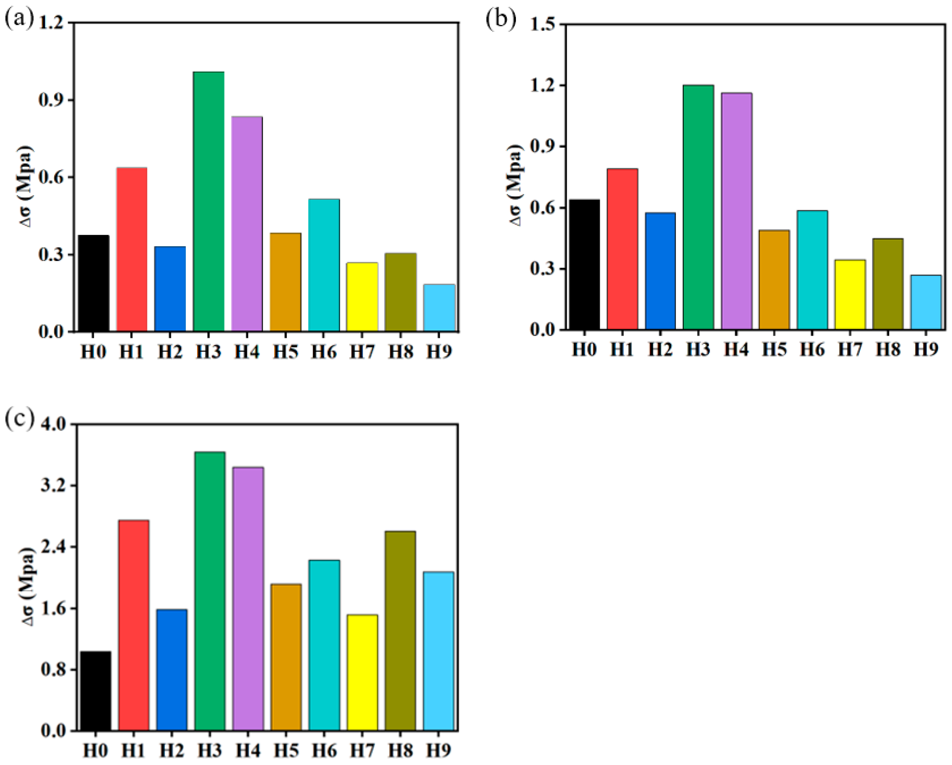
3.3. Load Uniformity

During the energy dissipation process, honeycomb sandwich panels should maintain good load uniformity to prevent fluctuations in reaction forces that could cause damage to both the energy-absorbing structure and the protected end. Ideally, the reaction force of a honeycomb sandwich panel should remain at a constant value. Here, the load uniformity of honeycombs can be evaluated using the Δσ indicator, as described in [6]:
Δ σ = ε 0 ε d σ σ p d ε / ε d ε 0
where σp is defined as the plateau stress of the honeycomb sandwich panel, that is, the average value of the nominal stress between the initiation strain ε0 and the densification strain εd. As shown in Figure 10, the initiation strain ε0 is the strain corresponding to the initiation peak stress, and the densification strain εd is the strain corresponding to the stress equal to the initial peak stress in the last rapidly increasing stage of the nominal stress [45]. It is an important characteristic value that signifies the mechanical performance of the honeycomb sandwich panel.
σ p = ε 0 ε d σ d ε / ε d ε 0
Δσ represents the average value of the magnitude of nominal stress fluctuations in the honeycomb sandwich panel. The smaller the value of Δσ, the better the load uniformity of the honeycomb sandwich panels, which is more advantageous for the energy-absorbing structure. As an ideal honeycomb energy-absorbing structure, Δσ = 0.
Figure 11 presents the numerical simulation results of load uniformity of different types of honeycomb sandwich panels under various impact velocities. For comparative analysis, the calculation results of the circular honeycomb sandwich panel are also provided in this figure. As shown in this figure, the load uniformity of the hourglass honeycomb sandwich panel is related to both the geometric parameters and the impact velocity conditions of the honeycomb sandwich panel.
Under low-velocity-impact conditions (v = 2 m/s), different honeycomb sandwich panels exhibit significant differences in load uniformity, as shown in Figure 11a. Comparing and analyzing the wall thickness, it can be seen that the load uniformity of hourglass honeycomb sandwich panels decreases with increasing honeycomb wall thickness. This is because as the thickness of the honeycomb wall increases, the strength and stiffness of the hourglass honeycomb sandwich panel increase, resulting in higher peak stresses and stronger vibrations during the initiation contact dissipation of energy, and the load uniformity of the structure decreases. Additionally, it can be observed from the graph that under the same relative density conditions, the load uniformity of the H1-type hourglass honeycomb sandwich panel is inferior to that of the circular honeycomb sandwich panel. This is because the cross-section of the hourglass honeycomb sandwich panel changes along the direction of dynamic crushing compression, while the cross-section of the circular honeycomb sandwich panel remains unchanged along the direction of dynamic crushing compression. Comparing and analyzing the inclination angle, it reveals that the larger the inclination angle of the honeycomb wall, the better the load uniformity of the panel. This is because the larger the inclination angle of the honeycomb wall, the stronger the bending load-bearing effect and the weaker the tensile–compressive load-bearing effect of the structure under external dynamic crushing compression conditions, resulting in a smoother change in load. Comparative analysis of the maximum radius reveals that the smaller the maximum radius of the honeycomb cell, the better the load uniformity of the structure. The load uniformity of the H7-type hourglass honeycomb sandwich panel is superior to that of the circular honeycomb sandwich panel. This is because the smaller the maximum radius of the honeycomb cell in the hourglass honeycomb sandwich panel, the smaller the distance between the hourglass honeycomb cell and the panel contact points, the stronger the overall stability of the sandwich panel, the more uniform the stress distribution under compression load, and the less likely local buckling failure is to occur under compression load. Comparative analysis of different layers reveals that with the increase in the number of layers of the hourglass honeycomb, the load uniformity of the hourglass honeycomb sandwich panel improves. This is because increasing the number of layers of the honeycomb panel helps to evenly distribute the load, and in the case of axial multilayer panels, there are more supporting layers, improving the uniformity of the axial compression load of the structure, and single-layer panels are more prone to local stress concentration.
Impact velocity conditions are important factors affecting the mechanical properties of honeycomb sandwich panels. With the increase in impact velocity (v = 30 m/s), both the load uniformity of the hourglass honeycomb sandwich panel and the circular honeycomb sandwich panel show a tendency to decrease, but the relative results of the load uniformity of different hourglass honeycomb sandwich panels remain unchanged, as shown in Figure 11b. This indicates that within a certain range, increasing the velocity will cause oscillations in the dynamic crushing stress in the honeycomb and will reduce the load uniformity of the honeycomb, but the geometric parameters are still the main influencing factors. When the impact velocity condition is further increased (v = 120 m/s), the load uniformity of both the hourglass honeycomb sandwich panel and the circular honeycomb sandwich panel becomes worse, and the degree of change in the load uniformity of different hourglass honeycomb sandwich panels varies, with the circular honeycomb sandwich panel showing the best load uniformity, as shown in Figure 11c. This indicates that when the impact velocity condition is sufficiently large, the impact velocity is the dominant factor affecting the load uniformity, the influence of the honeycomb configuration is more important, and the influence of geometric parameters is very small.

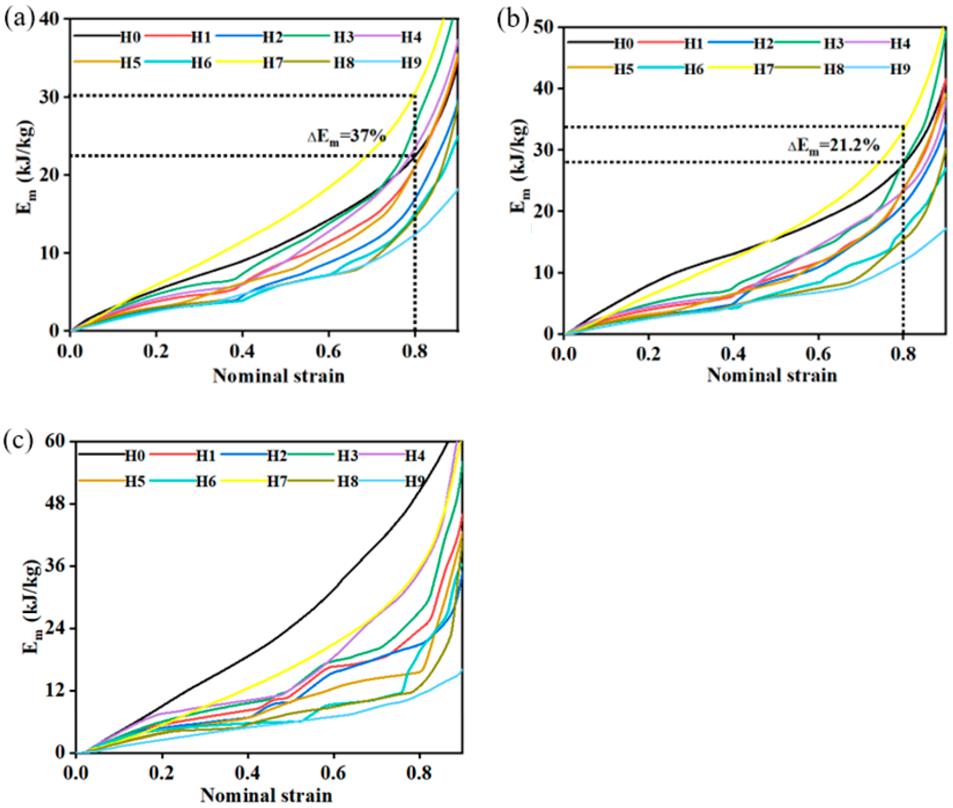
3.4. Energy Absorption

One important functional characteristic of honeycomb sandwich panels is their application as energy-absorbing structures in engineering collision protection devices. Among these, the specific energy absorption rate per unit is a common indicator to quantify the energy absorption capacity of honeycomb sandwich panels [46].
E m = E v Δ ρ ρ s
where Ev represents the specific strain energy of the honeycomb sandwich panel per unit volume.
E v = 0 ε d σ d ε
Figure 12 presents the numerical simulation results of the specific energy absorption of hourglass honeycomb sandwich panels under different impact velocities. For the purpose of comparative analysis, the calculation results for circular honeycomb sandwich panels with the same relative density are also provided in this figure.
As shown in Figure 12, under low-velocity-impact conditions (v = 2 m/s), the geometric parameters of the hourglass honeycomb sandwich panel are the main factors affecting its energy absorption capability. The unit mass energy absorption rate of the hourglass honeycomb sandwich panel is directly proportional to the thickness of the honeycomb walls and inversely proportional to the inclination angle of the honeycomb walls. Thicker honeycomb walls and smaller inclination angles result in stronger energy absorption capabilities for the hourglass honeycomb sandwich panel. The circular honeycomb can be regarded as an hourglass honeycomb with an inclination angle of 0. Therefore, under the same relative density conditions, the energy absorption capability of the circular honeycomb sandwich panel is generally higher than that of the hourglass honeycomb sandwich panel. This result also corroborates the aforementioned comparative conclusions. Additionally, it can be observed from this figure that the maximum radius of the honeycomb cells of the hourglass honeycomb sandwich panel is an important geometric parameter affecting its energy absorption capability, and the distance between the contact points of the hourglass honeycomb cell and panel has a significant influence on the overall stability and energy absorption capability of the sandwich panel. Among the different hourglass honeycomb sandwich panels, only the H7 type demonstrates significantly better energy absorption capabilities than the circular honeycomb sandwich panel. At ε = 0.8, the H7-type hourglass honeycomb sandwich panel exhibits a 37% higher unit mass energy absorption efficiency than that of the circular honeycomb sandwich panel (as shown in Figure 12a).
With the increase in impact velocity (v = 30 m/s), the influence of impact velocity begins to manifest. At ε = 0.8, the H7-type hourglass honeycomb sandwich panel demonstrates a 21.2% higher unit mass energy absorption efficiency compared to the circular honeycomb sandwich panel (as shown in Figure 12b). Further increasing the impact velocity (v = 120 m/s) causes the energy absorption process to occur rapidly, and the influence of geometric parameters decreases, so the impact velocity becomes the main factor affecting the energy absorption capability of the hourglass honeycomb sandwich panel. The energy absorption capability of the circular honeycomb sandwich panel is stronger than that of the hourglass honeycomb sandwich panel. However, the energy absorption capabilities of the H4- and H7-type hourglass honeycomb sandwich panels are very close to that of the circular honeycomb sandwich panel.

4. Conclusions

This study proposes and establishes a model of an hourglass honeycomb sandwich panel for the first time, providing a theoretical equation for calculating its relative density. The influence of the geometric parameters on the dynamic performance of the hourglass honeycomb sandwich panel under different impact velocities is discussed.
Under the dynamic crushing compression condition of a rigid plate, the deformation mode, dynamic response, load uniformity, and energy absorption capability of the hourglass honeycomb sandwich panel are related to the geometric parameters and impact velocity conditions. Under low-velocity-impact conditions, the influence of geometric parameters is dominant, whereas the influence of impact velocity is minimal. Under high-velocity-impact conditions, the influence of the impact velocity is dominant, with minimal influence from the geometric parameters. Compared with the circular honeycomb sandwich panel, the deformation mode of the hourglass honeycomb sandwich panel was less affected by the impact velocity conditions, and the ability of self-adaptation to changes in impact velocity was stronger. The hourglass honeycomb sandwich panel with low density, large honeycomb wall inclination angle, and a small distance between contact points of the hourglass honeycomb cell and panel has excellent load uniformity, but it decreases with increasing impact velocity. The distance between the hourglass honeycomb cell and the panel contact points had a significant dynamic crushing effect on the energy absorption capability of the sandwich panel, and the H7-type hourglass honeycomb sandwich panel exhibited excellent energy absorption capabilities under different impact velocity conditions.
In summary, the “open-celled” architecture of the hourglass honeycomb sandwich panel breaks through the bottleneck of the closed space of the internal unit structure of existing honeycomb sandwich panels, which can help immensely in integrated designs of multifunction systems compared to common enclosed sandwich panels, such as wiring installation, embedded energy-absorbing materials or fireproof materials, and liquid storage. In addition, it can help optimize product design and enhance performance by controlling the geometric parameters.

Author Contributions

Conceptualization, X.C., K.W. and H.W.; Methodology, X.C. and K.W.; Software, X.C.; Validation, K.W. and L.C.; Investigation, X.C., P.G. and J.Q.; Resources, K.W.; Writing—Original Draft Preparation, X.C.; Writing—Review and Editing, K.W. and H.W.; Supervision, L.C. and H.W. All authors have read and agreed to the published version of the manuscript.

Funding

This research was funded by the National Natural Science Foundation of China (No. 12302118).

Data Availability Statement

The original contributions presented in the study are included in the article, further inquiries can be directed to the corresponding authors.

Conflicts of Interest

The authors declare no conflicts of interest.

References

  1. Li, Q.M.; Sun, Y.L. Dynamic compressive behavior of cellular materials: A review of phenomenon, mechanism and modeling. Int. J. Impact Eng. 2018, 112, 74–115. [Google Scholar] [CrossRef]
  2. Qi, C.; Jiang, F.; Yang, S. Advanced honeycomb designs for improving mechanical properties: A review. Compos. Part B 2021, 227, 109393. [Google Scholar] [CrossRef]
  3. Arunkumar, M.P.; Pitchaimani, J.; Gangadharan, K.V.; Lenin Babu, M.C. Influence of nature of core on vibro acoustic behavior of sandwich aerospace structures. Aerosp. Sci. Technol. 2016, 56, 155–167. [Google Scholar] [CrossRef]
  4. Ning, H.; Janowski, G.M.; Vaidya, U.K.; Husman, G. Thermoplastic sandwich structure design and manufacturing for the body panel of mass transit vehicle. Compos. Struct. 2007, 80, 82–91. [Google Scholar] [CrossRef]
  5. Guo, H.Y.; Yuan, H.; Zhang, J.X.; Ruan, D. Review of sandwich structures under impact loadings: Experimental, numerical and theoretical analysis. Thin-Walled Struct. 2024, 196, 111541. [Google Scholar] [CrossRef]
  6. Hanssen, A.G.; Langseth, M.; Hopperstad, O.S. Static and dynamic crushing of circular aluminium extrusions with aluminium foam filler. Int. J. Impact Eng. 2000, 24, 475–507. [Google Scholar] [CrossRef]
  7. Zhang, X.; Cheng, G.D.; Zhang, H. Numerical investigations on a new type of energy-absorbing structure based on free inversion of tubes. Int. J. Mech. Sci. 2009, 51, 64–76. [Google Scholar] [CrossRef]
  8. Wu, H.X.; Liu, Y.; Zhang, X.C. In-plane crushing behavior and energy absorption design of composite honeycombs. Acta Mech. Sin. 2018, 34, 1108–1123. [Google Scholar] [CrossRef]
  9. Cooper, G.J.; Townend, D.J.; Cater, S.R.; Pearce, B.P. The role of stress waves in thoracic visceral injury from blast loading: Modification of stress transmission by foams and high-density materials. J. Biomech. 1991, 24, 273–285. [Google Scholar] [CrossRef]
  10. Zhu, Y.; Wang, Z.P.; Poh, L.H. Auxetic hexachiral structures with wavy ligaments for large elasto-plastic deformation. Smart Mater. Struct. 2018, 27, 055001. [Google Scholar] [CrossRef]
  11. Zhang, Q.; Yang, X.; Li, P.; Huang, G.; Feng, S.; Shen, C.; Han, B.; Zhang, X.; Jin, F.; Xu, F.; et al. Bioinspired engineering of honeycomb structure—Using nature to inspire human innovation. Prog. Mater. Sci. 2015, 74, 332–400. [Google Scholar] [CrossRef]
  12. Ruan, D.; Lu, G.; Wang, B.; Yu, T.X. In-plane dynamic crushing of honeycombs—A finite element study. Int. J. Impact Eng. 2003, 28, 161–182. [Google Scholar] [CrossRef]
  13. Tan, P.J.; Reid, S.R.; Harrigan, J.J.; Zou, Z.; Li, S. Dynamic compressive strength properties of aluminium foams. Part I—Experimental data and observations. J. Mech. Phys. Solids 2005, 53, 2174–2205. [Google Scholar] [CrossRef]
  14. Tan, P.J.; Reid, S.R.; Harrigan, J.J.; Zou, Z.; Li, S. Dynamic compressive strength properties of aluminium foams. Part II—‘Shock’ theory and comparison with experimental data and numerical models. J. Mech. Phys. Solids 2005, 53, 2206–2230. [Google Scholar] [CrossRef]
  15. Li, N.; Liu, S.Z.; Wu, X.N.; Wang, J.Y.; Han, Y.S.; Zhang, X.C. Mechanical characteristics of a novel rotating star-rhombic auxetic structure with multi-plateau stages. Thin-Walled Struct. 2023, 191, 111081. [Google Scholar] [CrossRef]
  16. Liao, S.F.; Zheng, Z.J.; Yu, J.L. Dynamic crushing of 2D cellular structures: Local strain field and shock wave velocity. Int. J. Impact Eng. 2013, 57, 7–16. [Google Scholar] [CrossRef]
  17. Jin, T.; Zhou, Z.W.; Wang, Z.H.; Wu, G.Y.; Shu, X.F. Experimental study on the effects of specimen in-plane size on the mechanical behavior of aluminum hexagonal honeycombs. Mater. Sci. Eng. A 2015, 635, 23–35. [Google Scholar] [CrossRef]
  18. Qi, C.; Remennikov, A.; Pei, L.; Yang, S.; Yu, Z.; Ngo, T. Impact and close-in blast response of auxetic honeycomb-coredsandwich panels: Experimental tests and numerical simulations. Compos. Struct. 2017, 180, 161–178. [Google Scholar] [CrossRef]
  19. Rapaka, S.D.; Pandey, M.; Annabattula, R.K. Dynamic compressive behaviour of auxetic and non-auxetic hexagonal honeycombs with entrapped gas. Int. J. Impact Eng. 2020, 146, 103718. [Google Scholar] [CrossRef]
  20. Wang, Z.; Deng, J.; Liu, K.; Tao, Y. Hybrid hierarchical square honeycomb with widely tailorable effective in-plane elastic modulus. Thin-Walled Struct. 2022, 171, 108816. [Google Scholar] [CrossRef]
  21. Brothers, A.H.; Dunand, D.C. Density-Graded Cellular Aluminum. Adv. Eng. Mater. 2006, 8, 805–809. [Google Scholar] [CrossRef]
  22. Zheng, X.; Smith, W.; Jackson, J.; Moran, B.; Cui, H.; Chen, D.; Ye, J.; Fang, N.; Rodriguez, N.; Weisgraber, T.; et al. Multiscale metallic metamaterials. Nat. Mater. 2016, 15, 1100–1106. [Google Scholar] [CrossRef] [PubMed]
  23. Zhang, X.C.; Liu, N.N.; An, C.C.; Wu, H.X.; Li, N.; Hao, K.M. Dynamic crushing behaviors and enhanced energy absorption of bio-inspired hierarchical honeycombs with different tipologies. Def. Technol. 2023, 22, 99–111. [Google Scholar] [CrossRef]
  24. Wei, L.; Zhao, X.; Yu, Q.; Zhu, G.H. A novel star auxetic honeycomb with enhanced in-plane crushing strength. Thin-Walled Struct. 2020, 149, 106623. [Google Scholar] [CrossRef]
  25. Li, S.; Liu, Z.; Shim, X.P.W.; Guo, Y.; Sun, Z.; Li, X.; Wang, Z. In-plane compression of 3D-printed self-similar hierarchical honeycombs—Static and dynamic analysis. Thin-Walled Struct. 2020, 157, 106990. [Google Scholar] [CrossRef]
  26. Chen, B.C.; Zou, M.; Liu, G.M.; Song, J.F.; Wang, H.X. Experimental study on energy absorption of bionic tubes inspired by bamboo structures under axial crushing. Int. J. Impact Eng. 2018, 115, 48–57. [Google Scholar] [CrossRef]
  27. Ajdari, A.; Babaee, S.; Vaziri, A. Mechanical properties and energy absorption of heterogeneous and functionally graded cellular structures. Procedia Eng. 2011, 10, 219–223. [Google Scholar] [CrossRef]
  28. Shen, C.J.; Yu, T.X.; Lu, G. Double shock mode in graded cellular rod under impact. Int. J. Solids Struct. 2013, 50, 217–233. [Google Scholar] [CrossRef]
  29. Zhang, X.C.; An, L.Q.; Ding, H.M. Dynamic crushing behavior and energy absorption of honeycombs with density gradient. J. Sandw. Struct. Mater. 2014, 16, 125–147. [Google Scholar] [CrossRef]
  30. Qiao, J.X.; Chen, C.Q. Impact resistance of uniform and functionally graded auxetic double arrowhead honeycombs. Int. J. Impact Eng. 2015, 83, 47–58. [Google Scholar] [CrossRef]
  31. Lu, Z.X.; Liu, Q.; Yang, Z.Y. Predictions of Young’s modulus and negative Poisson’s ratio of auxetic foams. Phys. Status Solidi B-Basic Solid State Phys. 2011, 248, 167–174. [Google Scholar] [CrossRef]
  32. Prawoto, Y. Seeing auxetic materials from the mechanics point of view: A structural review on the negative Poisson’s ratio. Comput. Mater. Sci. 2012, 58, 140–153. [Google Scholar] [CrossRef]
  33. Zhao, M.D.; Yuan, H.; Du, J.L.; Wu, X.W.; Zhang, J.X. Plastic behavior of foam-filled negative Poisson’s ratio beams. Eng. Struct. 2022, 273, 115092. [Google Scholar] [CrossRef]
  34. Yang, H.; Wang, B.; Ma, L. Designing hierarchical metamaterials by topology analysis with tailored Poisson’s ratio and Young’s modulus. Compos. Struct. 2019, 214, 359–378. [Google Scholar] [CrossRef]
  35. Papka, S.D.; Kyriakides, S. Biaxial crushing of honeycombs—Part I: Experiments. Int. J. Solids Struct. 1999, 36, 4367–4396. [Google Scholar] [CrossRef]
  36. Papka, S.D.; Kyriakides, S. In-plane biaxial crushing of honeycombs—Part II: Analysis. Int. J. Solids Struct. 1999, 36, 4397–4423. [Google Scholar] [CrossRef]
  37. Chung, J.; Wass, A.M. Compressive response of circular cell polycarbonate honeycombs under in-plane biaxial static and dynamic loading. Part I: Experiments. Int. J. Impact Eng. 2002, 27, 729–754. [Google Scholar] [CrossRef]
  38. Chung, J.; Wass, A.M. Compressive response of circular cell polycarbonate honeycombs under inplane biaxial static and dynamic loading—Part II: Simulations. Int. J. Impact Eng. 2002, 27, 1015–1047. [Google Scholar] [CrossRef]
  39. Mei, J.; Liu, J.Y.; Liu, J.L. A novel fabrication method and mechanical behavior of all-composite tetrahedral truss core sandwich panel. Compos. Part A 2017, 102, 28–39. [Google Scholar] [CrossRef]
  40. Mines, R.A.W.; Tsopanos, S.; Shen, Y.; Hasan, R.; McKown, S.T. Drop weight impact behaviour of sandwich panels with metallic micro lattice cores. Int. J. Impact Eng. 2013, 60, 120–132. [Google Scholar] [CrossRef]
  41. Alghamdi, A.A.A. Collapsible impact energy absorbers: An overview. Thin-Walled Struct. 2001, 39, 189–213. [Google Scholar] [CrossRef]
  42. Pan, J.W.; Lyu, M.Q.; Li, M.; Cai, J.G. In-plane dynamics crushing of a reinforced honeycomb with enhanced energy absorption. Int. J. Impact Eng. 2024, 183, 104807. [Google Scholar] [CrossRef]
  43. Zhang, X.; Zhang, H.; Wen, Z. Experimental and numerical studies on the crush resistance of aluminum honeycombs with various cell configurations. Int. J. Impact Eng. 2014, 66, 48–59. [Google Scholar] [CrossRef]
  44. Wu, H.X.; Qu, J.; Wu, L.Z. Experimental and numerical study on impact behavior of hourglass lattice sandwich structures with gradients. Materials 2023, 16, 6275. [Google Scholar] [CrossRef] [PubMed]
  45. Li, Q.M.; Magkiriadis, I.; Harrigan, J.J. Compressive Strain at the Onset of Densification of Cellular Solids. J. Cell. Plast. 2006, 42, 371–392. [Google Scholar] [CrossRef]
  46. Kooistra, G.W.; Deshpande, V.S.; Wadley, H.N.G. Compressive behavior of age hardenable tetrahedral lattice truss structures made from aluminum. Acta Mater. 2004, 52, 4229–4237. [Google Scholar] [CrossRef]
Figure 1. Computational model of hourglass honeycomb sandwich panel.
Aerospace 11 00881 g001
Figure 2. Geometric model: (a) hourglass honeycombs; (b) unit cell configuration.
Aerospace 11 00881 g002
Figure 3. Comparative validation of experimental results and simulated results for sandwich panels: (a) static experimental results [43]; (b) dynamic experimental results [44].
Aerospace 11 00881 g003
Figure 4. Deformation patterns at v = 2 m/s: (a) circular honeycomb sandwich panel (H0); (b) hourglass honeycomb sandwich panel (H1).
Aerospace 11 00881 g004
Figure 5. Deformation patterns at v = 30 m/s: (a) circular honeycomb sandwich panel (H0); (b) hourglass honeycomb sandwich panel (H1).
Aerospace 11 00881 g005
Figure 6. Deformation patterns at v = 120 m/s: (a) circular honeycomb sandwich panel (H0); (b) hourglass honeycomb sandwich panel (H1).
Aerospace 11 00881 g006
Figure 7. Nominal stress–strain curves of honeycomb sandwich panels at v = 2 m/s: (a) different honeycomb wall thicknesses; (b) different honeycomb wall inclination angles; (c) different maximum cell radii; (d) different numbers of honeycomb core layers.
Aerospace 11 00881 g007
Figure 8. Nominal stress–strain curves of honeycomb sandwich panels at v = 30 m/s: (a) different honeycomb wall thicknesses; (b) different honeycomb wall inclination angles; (c) different maximum cell radii; (d) different numbers of honeycomb core layers.
Aerospace 11 00881 g008
Figure 9. Nominal stress–strain curves of honeycomb sandwich panels at v = 120 m/s: (a) different honeycomb wall thicknesses; (b) different honeycomb wall inclination angles; (c) different maximum cell radii; (d) different numbers of honeycomb core layers.
Aerospace 11 00881 g009
Figure 10. Nominal stress–strain curves of honeycombs.
Aerospace 11 00881 g010
Figure 11. The load uniformity of honeycomb sandwich panels under different impact velocities: (a) v = 2 m/s; (b) v = 30 m/s; (c) v = 120 m/s.
Aerospace 11 00881 g011
Figure 12. The unit mass energy absorption curves of honeycomb sandwich panels under different impact conditions: (a) v = 2 m/s; (b) v = 30 m/s; (c) v = 120 m/s.
Aerospace 11 00881 g012
Table 1. Geometric parameters of hourglass honeycombs.
Modelnb (mm)h (mm)t (mm)α
H0110100.1
H1110100.12220°
H2110100.07220°
H3110100.17220°
H4110100.10910°
H5110100.14130°
H6120100.2220°
H715100.07520°
H821050.1120°
H93103.30.10620°
Disclaimer/Publisher’s Note: The statements, opinions and data contained in all publications are solely those of the individual author(s) and contributor(s) and not of MDPI and/or the editor(s). MDPI and/or the editor(s) disclaim responsibility for any injury to people or property resulting from any ideas, methods, instructions or products referred to in the content.

