Abstract
The objective of the kinematic model of rock chips is to examine the impact of the driving parameters of drilling tools on the effective chip removal speed, with a view to analyze the chip removal performance of rotary percussion ultrasonic drilling. The discrete element numerical simulation method, EDEM-2022 simulation software, was employed to establish a simulation model, match the simulation parameters, and conduct a simulation study of chip removal under the action of rotary percussion. This was performed to analyze the influence of the driving parameters on the chip conveying process. In order to ascertain the order of parameters affecting the degree of conveyance rate as well as the optimal driving parameters, orthogonal experiments were designed based on Taguchi’s experimental analysis method.
1. Introduction
Asteroid exploration has become a research hot spot due to the continuous development of deep space exploration technology [1,2,3]. Studying asteroids can help us understand the formation and evolution of the solar system as they contain geological information from its early stages. Acquiring asteroid rock samples has become a crucial goal of deep space exploration missions [4,5,6,7]. Drill sampling is a crucial method for obtaining rock samples. Current drilling and sampling techniques primarily rely on traditional sampling equipment powered by electromagnetic motors [8,9,10]. As the depth of drilling increases, so does the necessary drilling pressure and driving torque of the sampling device [11]. However, traditional sampling devices face challenges in meeting the increasing drilling pressure and power requirements due to the limited payload and the energy source of the probe. Additionally, the weak gravity field of asteroids and the risk of the probe tipping over from excessive drilling pressure further restrict traditional sampling devices’ use in deep space exploration.
Previous studies have demonstrated that ultrasonic drillers utilizing piezoelectric ceramics can obtain rock samples with low drilling pressures and power consumption. Ultrasonic drillers have a wider temperature range and are more compact compared to conventional drillers powered by electromagnetic motors, making them a promising option for deep space exploration [12,13].
Ultrasonic drilling can be classified into two categories based on their working principles: impact ultrasonic drilling and rotary percussive ultrasonic drilling. Ultrasonic drilling has had a significant impact on the development of drilling tools. The U.S. Jet and Propulsion Laboratory (JPL) developed the Ultrasonic/Sonic Driller Corer (USDC) device [14]. The European Space Agency (ESA) developed Ultrasonic Drilling Tools (UDT) and ultrasonic rock samplers [15]. The University of Glasgow in the UK developed an ultrasonic rock sampler [16,17], while Nanjing University of Aeronautics and Astronautics developed ultrasonic/sonic drilling [18]. Additionally, the Harbin Institute of Technology developed the Ultrasonic Coring Tool (UCT) [19]. The ultrasonic drilling technique transmits longitudinal vibrations from the piezoelectric stack to the drilling tool through the amplifier rod. This allows the drilling tool to penetrate rock with low drilling pressure and power consumption thanks to the high-frequency impact movement. It is a precise and efficient method of drilling. Although longitudinal or torsional vibrations of the drilling tool can dislodge some rock debris, the ability to do so is limited. Therefore, the efficiency of percussive ultrasonic drilling still requires improvement [20,21,22].
In 1982, Japanese scholar Toshiiku Sashida put forth a proposal for a mode conversion type ultrasonic motor which employs the “Langzhiwan” ultrasonic oscillator as the driving source. This configuration comprises an ultrasonic oscillator and rotor with an approximately 6° angle between them. The ultrasonic oscillator is in longitudinal vibration at the same time as the top of the vibration plate produces a tangential vibration. The two vibrations are coupled, thereby forming an elliptical driving motion. During operation, the wedge-shaped ultrasonic motor displays increased wear and tear between the driving plate at the front of the ultrasonic vibrator and the rotor [23].
Japanese scholar Akio Kumada put forth a novel ultrasonic motor design based on a single beam coupled vibrator [24]. The single-beam coupled vibrator comprises three main components: the bottom support leg, the middle disc, and the top rectangular beam. Its primary function is to facilitate the transfer of longitudinal vibration from the bottom support leg to the top rectangular beam, which in turn induces torsional vibration in the rectangular beam, thereby forming an elliptical vibration at the point of contact between the rectangular beam and the rotor. This vibration then drives the rotor to produce rotary motion. The test demonstrated that the ultrasonic motor exhibited a maximum torque of 1.3 Nm and a maximum speed of 120 r/min. However, the single-beam vibrator ultrasonic motor exhibited a phenomenon of instability in speed.
Japanese scholar Tsujino conducted extensive research on the chute modal conversion ultrasonic motor, which features a cylindrical longitudinal torsion oscillator main structure. The outer circumference of this structure is arranged with several chutes, and the chutes themselves are electrical discharge machining (EDM). The longitudinal vibration transmitted by the piezoelectric stack generates both longitudinal and torsional vibration at the chute. The driving surface of the ultrasonic motor is coupled to form an elliptical motion in the chute modal conversion ultrasonic motor, thereby driving the rotor to rotate. The diameter of the main body of the motor is 15 mm, and the maximum rotational torque obtained in the test is 0.22 Nm. Subsequently, Japanese scholar Tsujino and colleagues developed a two-chute modal conversion ultrasonic motor, building upon the principles of a single-chute modal conversion ultrasonic motor. Under identical power conditions, the output speed and torque of the double-chute ultrasonic motor are observed to be superior to those of the single-chute ultrasonic motor. With an ultrasonic motor diameter of 15 mm, the double-chute drive speed can exceed 300 rotations per minute [25,26,27,28,29].
A chute modal conversion ultrasonic motor was developed by Korean scholar Tae-Gone Park and colleagues [30]. The distinction between the chute ultrasonic motor and the chute ultrasonic motor examined by Japanese scholars is that the chute of the former directly penetrates the cylindrical surface. Furthermore, the impact of chute parameter alterations on the longitudinal torsional vibration of the ultrasonic motor is investigated through the utilization of the finite element method. Based on the aforementioned prototype, an output test of the ultrasonic motor was conducted, resulting in a resonant frequency of 42.9 kHz, a maximum output speed of 33.3 r/min, and a maximum rotary torque of 0.16 Nm.
The research team of Academician Chunsheng Zhao of Nanjing University of Aeronautics and Astronautics has conducted research on the slant slot-like mode conversion ultrasonic motor and proposed a novel type of ultrasonic motor incorporating an array of holes [31,32,33]. The design concept entails utilizing the longitudinal configuration of minute apertures in lieu of the conventional oblique groove configuration, thereby facilitating the transformation of longitudinal vibration into longitudinal torsion coupling vibration. Each diagonal groove is substituted with three small holes with a diameter of 2 mm. The prototype was tested for output performance, and the resulting data indicated that the maximum speed of the ultrasonic motor is 1000 r/min at a drive voltage of 200 V, with a maximum slewing torque of 0.15 Nm.
Given that the slotted conversion oscillator is cylindrical in shape, the curved slotted groove must be machined using electrical discharge machining (EDM), a process that is inherently complex. The use of mechanically coupled vibrators allows for greater flexibility in design, which can be employed in rotary impact ultrasonic drilling apparatus.
The rotary percussive ultrasonic drill employs a rotary motion to drive the rotation of the drill tool, thereby enhancing the efficiency of chip removal. Rotary motion can be divided into two kinds: motorized rotary and piezoelectric rotary, depending on the driving method. Motorized rotary percussive ultrasonic drilling uses an electromagnetic motor to drive the rotary drilling tool. Examples of this include rotary-assisted ultrasonic drilling [34] developed by JPL, ultrasonic capsule gopher (auto-gopher) [16,17], and ultrasonic planetary core drilling (UPCD) developed by the University of Glasgow in the United Kingdom. The inclusion of motorized rotary motion can enhance the efficiency of chip removal, but it also adds complexity to the sampling and control systems.
Piezoelectric rotary percussive ultrasonic drilling involves using a piezoelectric ceramic drive drilling tool to generate rotary motion for the rotary drilling tool, such as the JPL-developed single piezoelectric actuator rotary impact coupling type driller [35]. The ultrasonic driller uses an amplitude-variable rod to convert longitudinal vibration into longitudinal-torsional compound vibration, which directly drives the drilling tool to generate rotary impact motion. However, the rotary and impact motions of the drill tool are coupled, making it difficult to adjust them individually.
The article proposes a Rotary-Percussive Ultrasonic Driller (RPUD) that utilizes the vibration of both sides of a piezoelectric stack. Unlike existing ultrasonic drillers that only use the vibration on one side of the stack, the RPUD is excited by a resonant voltage and transmits vibrations to both sides simultaneously. This ultrasonic driller relies solely on a single piezoelectric stack as its power source. It transforms one side’s vibration into the impact motion of the driller and the other side’s vibration into its rotary motion. The rotary percussion ultrasonic drill combines the characteristics of the percussion ultrasonic drill, which can break rock with less power consumption and lower drilling pressure, with a rotary function to assist with chip removal and enhance drilling efficiency.
2. Composition and Working Principle of Rotary Percussion Ultrasonic Drilling System
In order to effectively combine the slewing impact movement, the proposed rotary percussive ultrasonic drill is driven by a single piezoelectric stack, which is excited by a resonant voltage and transmits vibrations to both sides simultaneously. This is an improvement over existing ultrasonic drillers, which only use the vibration of one side of the piezoelectric transducer and do not make full use of its potential. The bilaterally driven piezoelectric stack is the key principle behind this innovation. This ultrasonic driller utilizes the vibration of a single piezoelectric stack to achieve both rotary and impact motion of the drilling tool. The vibration on one side is transformed into rotary motion, while the other side is transformed into impact motion. These motions can be adjusted independently.
When an electric field is applied in the direction of polarization of piezoelectric material, it produces a mechanical deformation in a linear relationship along the direction of polarization. This phenomenon is known as the inverse piezoelectric effect. The sandwich piezoelectric transducer is an energy conversion device that utilizes the inverse piezoelectric effect to convert electrical energy into acoustic energy. The device transforms voltage excitation at ultrasonic frequency into vibration energy output.
The piezoelectric transducer is composed of a sandwich-type structure consisting of a front cover plate, piezoelectric ceramic, rear cover plate, and bolts. When a resonant sinusoidal voltage excites the piezoelectric ceramic, the amplifier rods on both sides of the piezoelectric stack generate longitudinal reciprocating vibrations of the same frequency to both ends. Existing ultrasonic drillers only use the vibration of the front cover plate in the piezoelectric oscillator, while the vibration of the rear cover plate is not utilized. This thesis proposes a new type of rotary percussive ultrasonic drill that can simultaneously utilize the vibration of the front and rear cover plates of the piezoelectric oscillator based on the idea of utilizing the vibration energy of the front and rear cover plates.
The rotary percussive ultrasonic drill comprises a piezoelectric stack, a rotary unit, an impact unit, a drilling tool, and a support frame, as shown in Figure 1a. The piezoelectric stack comprises four PZT-8 ceramic discs located between the rotary unit and the impact unit. The slewing unit, located at the rear end of the piezoelectric stack, is composed of a V-coupled oscillator, a rotor, and a preloaded spring. The impact unit is positioned at the front end of the piezoelectric stack and includes an impact amplifier rod, a free mass, and a return spring. The drilling tool is situated at the front end of the free mass, and the support frame provides support for the entire ultrasonic driller.
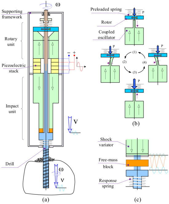
Figure 1.
Composition and working principle of rotary-percussive ultrasonic driller (RPUD). (a) Composition of rotary-percussive ultrasonic drill (RPUD). (b) Working principle of rotary unit in RPUD. (c) Working principle of percussive unit in RPUD.
Figure 1b,c illustrate the working principle of the rotary percussive ultrasonic drill. The piezoelectric stack transmits vibration to both the slewing unit and the impact unit when excited by a high-frequency resonant voltage. This causes the coupled oscillator and the impact amplifier rod to work in a resonant state. The slewing unit utilizes a coupled oscillator to transform longitudinal vibration from the piezoelectric stack into longitudinal and torsional compound vibration, resulting in an elliptical motion at the oscillator’s tip. Friction is generated between the contact surfaces of the coupling vibrator and the rotor as a consequence of the preload force provided by the preload spring between the coupling vibrator and the rotor. The frictional force drives the rotor to rotate, thereby producing a continuous rotary motion of the drilling tool.
In the shock unit, the shock amplifier rod amplifies longitudinal vibrations transmitted from the piezoelectric stack and transmits the motion downwards to the free mass. The resonance frequency of the piezoelectric transducer is 20 kHz; however, the vibration frequency of the drilling tool is generated by the transducer impacting the free mass block, which subsequently collides with the drilling tool. The free mass converts high-frequency longitudinal reciprocating vibration into low-frequency impact motion and transfers vibration energy to the drilling tool for rock breaking. It was observed that when a voltage of approximately 400 V was applied, the drilling tool was capable of reaching an amplitude of 0.6 mm following a collision with a free mass block. The tool’s motion is a combination of rotary motion from the rotary unit and impact motion from the impact unit [36,37].
3. Analysis of Rock Chip Transport Processes
During the process of rock drilling using a rotary percussive ultrasonic drill, the drill bit crushes the rock through ultrasonic impact. The spiral flute of the drilling tool then discharges the rock debris through rotary motion. The traditional screw conveying theory assumes that the crushed rock chips form a continuum. The conveying volume and load of the drilling tool are obtained through force analysis of the microelement of the rock chips. However, the rock chips in the drilling tool of a rotary percussive ultrasonic drill are affected not only by the spiral conveying process but also by the ultrasonic impact vibration. The rock cuttings not only move spirally upwards but also jump axially. A single spiral debris model is no longer suitable for analyzing the debris conveying process in the drilling tool of a rotary percussion ultrasonic drill. This paper analyzes the motion state of rock chip particles in the spiral groove of the drilling tool of the ultrasonic drilling rig. The analysis is based on the theory of spiral conveying and takes into account the force of the rock chip subjected to axial vibration.
During the drilling of rock using the rotary percussive ultrasonic drill, the drill tool undergoes impact motion fz in the OZ direction, rotary motion nz around the OZ axis, and feed velocity concerning the hole wall. The rock debris microelement in the drilling tool is involved in the motion, generating impact velocity vpf in the OZ direction, slewing velocity vde, and feed velocity vpz. Figure 2 shows the relationship between the upward velocity of rock chips along the OZ direction of the tool and the motion parameters of the auger tool [38,39].
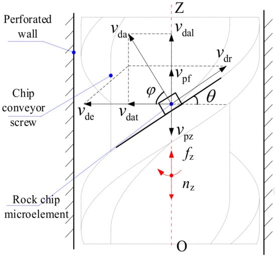
Figure 2.
Velocity analysis is of rock cuttings in the drilling tool.
The velocity at which the micro rock chip element slides along the spiral incline with the auger tool is represented by vdr. The friction angle between the rock chip and the ultrasonic driller’s auger tool is represented by θ, while φ represents the friction angle between the rock chip and the wall of the rock drill hole. The resultant velocity of the vertically upward velocity (vdal) and the horizontally oriented velocity (vdat) of the chip removal is (vda).
From the decomposition of each velocity and the relationship of the reference system, the following relationship exists among the velocities:
(vde − vdalcotφ)tanθ + vpf + vpz = vdal
The equation can be rewritten as
The formula above shows that the rock chip of the rotary percussive ultrasonic drilling machine is discharged due to the high-frequency impact and rotary coupling. The vertical upward speed of the chip (vdal) is influenced by the rotary speed (vde), impact speed (vpf), and feed speed (vpz).
The definition impacts the coefficient of circumferential chip removal.
The coefficient of influence for axial chip removal,
is defined in the following manner:
vdal = KTvde + KL (vpf + vpz)
The effective chip removal speed vdal is calculated by using numerical analysis to incorporate the driving parameters of the drilling tool, such as the impact frequency, impact amplitude, and rotary speed, into the equation during the drilling tool chip removal process. The parameters affecting the effective chip removal speed are simulated and experimentally verified subsequently to analyze the influence of different parameters on the chip removal ability of rotary percussive ultrasonic drilling.
4. Simulation Study of Rock Chip Transportation Process
4.1. Modeling of Discrete Element Simulation for Simulating Lunar Soil
This paper utilizes simulated lunar soil with a relative density of 85% to create a simulation model. The Rise-3002 particle image analyzer is used to collect images of the simulated lunar soil particles, which range in size from 0.1 mm to 1 mm. It is observed that the particle morphology is regular and irregular, among which the irregularity is more common in the form of elongated and angular particles. Irregularity is a common occurrence in the form of long and angular particles as shown in Figure 3. To improve simulation efficiency and reduce simulation time, both irregular and regularly shaped simulated lunar soil particles are equated to three-sphere coupled particles using the agglomeration method [40,41] in EDEM-2022 software. EDEM is a high-performance bulk and granular material simulation software. It uses DEM technology to quickly and accurately simulate and analyze the behavior of coal, ores, soils, fibers, grains, tablets, and powders. The fundamental premise of the simulation is founded upon the discrete element method, wherein the granular material is conceptualized as a vast array of discrete particles. Each particle is characterized by its own mass, shape, and material properties. During the simulation, EDEM calculates the trajectory of the particles by solving Newton’s second law and the interaction forces between the particles.
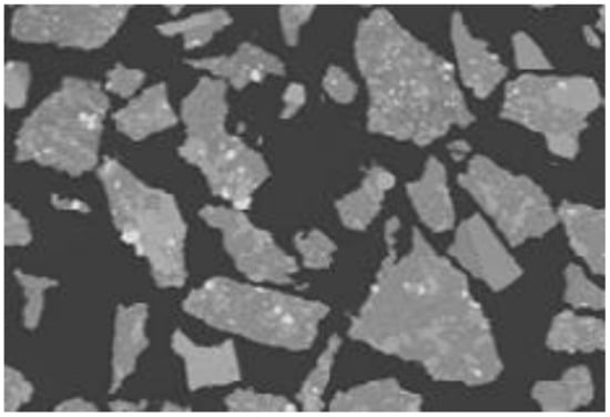
Figure 3.
Irregular lunar soil particles.
When modeling simulated lunar soil particles of equivalent type, irregular particles can be simplified into spheres with a radius equal to the average value of the radius of curvature at their two contact points. The elasticity model, as well as the adhesion energy of the equivalent spheres, can be set according to the ratio of the two radii of curvature to complete the modeling of simulated lunar soil particles of equivalent type.
The study indicates that the simulated particle size has a limited influence on the calculation results. The particle model used to simulate the flow of rock cuttings in the drilling tool is the Hertz–Mindlin with Bonding (HMB) contact model, which is based on the Parallel Bond Model discrete element model. Figure 4 illustrates the contact principle of the Parallel Bond Model discrete element model.

Figure 4.
Schematic diagram of Parallel Bond Model.
The Parallel Bond Model is a contact model that includes bonding units between two spherical particles. These units can limit the relative motion of the particles in both the normal and tangential directions up to a certain point. The structure is disrupted when the maximum normal and tangential stresses among the particles are reached.
At the initial moment, two particles are bound together under a certain cohesive force, and the interaction among the particles is governed by the HMB. As time progresses, the normal force (FN), tangential force (FT), and moments (MN and MT) among the particles change. These changes can be expressed as follows:
In Equation (6),
- RBC: Bonding radius (m);
- KN: normal stiffness (N/m);
- KT: tangential stiffness (N/m);
- δt: time step (s);
- VN: Normal velocity of particles (m/s);
- VT: Tangential velocity of particles (m/s);
- ωN: Normal angular velocity of particles (m/s);
- ωT: Tangential angular velocity of particles (m/s).
The assessment of bond failure between two particles is determined by whether the calculated normal and tangential stresses at a certain point in time exceed the set breaking strength. If this occurs, the bonding block fails and the bonding force becomes zero. Subsequently, the particles are kinetically calculated using the basic contact model (HMB) without a slip model. It is important to note that particles that lose the bonding effect are not bonded, even if contact occurs again.
4.2. Match the Simulation Parameters
The rock chip particles’ discrete element model was developed using DEM-Solutions’ discrete element calculation software, EDEM. The equivalent sample particles’ GEEM parameters were determined based on the Generic EDEM Material Model (GEMM) database design module which is shown in Figure 5.

Figure 5.
Process of choosing parameters for GEEM. (a) Particle size. (b) Repose angle of debris.
The simulation parameters for the rock chip sample particles in the simulation system are designed based on the Generic EDEM Material Model. The size range and density of the simulated sample particles are determined based on the simulated moonstone rock chips. Next, the initial parameters of the simulated particles are set to generate them. The initial particles are then dispersed in the software to form a conical pile, and the stacking angle of the modeled particles is measured. The stacking angle of the initial particles is compared to that of the real rock chip particles. The particle parameters are then adjusted and compared again until the stacking angle of the simulated model particles matches that of the real rock chip particles. Any differences are addressed by adjusting the particle parameters and comparing again until the stacking angle of the simulated model particles matches that of the real rock chip particles. The accumulation angle formed in the plane differs depending on the parameters of the particles after free fall. Consequently, the stacking angle is employed as a criterion for matching the parameters of lunar soil particles. The process is shown in Figure 6.
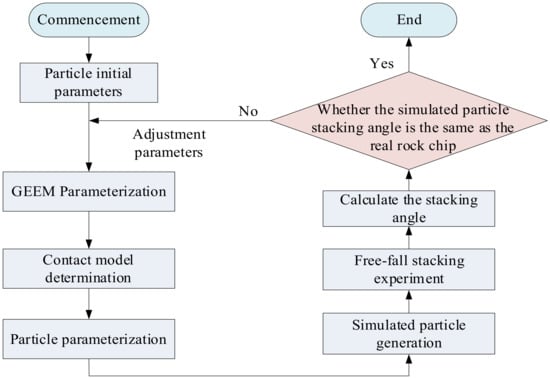
Figure 6.
Rock chip simulation model parameter matching calculation process.
A special tool was used to dump simulated lunar rock debris samples from a fixed height, and the particles fell freely onto a flat surface to form a conical pile. The stacking angle of the particles was measured to be 41.5° after the stacking was completed. The particle parameters employed in this study are also delineated in references [42,43].
The simulation initial values for the lunar rock debris particle contact model were obtained through a parameter-matching process involving numerous simulation experiments. The results are presented in Table 1.

Table 1.
Initial parameters of lunar soil simulant about distinct element modeling.
4.3. Analysis of Chip Removal Motion under Rotary Impact
The debris removal process of rock chip particles in the spiral groove of the ultrasonic drilling tool was simulated using the HMB. The parameters matched in the previous section were used. The motion state of the particles was directly observed and measured using the discrete cell method.
Figure 7a–e illustrates the chip removal process of a rotary percussive ultrasonic drilling tool. The colors of the particles indicate the axial motion speed, with blue representing low speed and red representing high speed.
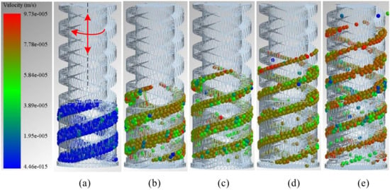
Figure 7.
Chip removal process of drilling tools under rotary-percussive movement. (a) The initial state of the particles. (b) Particle state at 0.5 s. (c) Particle state at 1 s. (d) Particle state at 1.5 s. (e) Particle state at 2 s.
The drilling tool’s initial driving parameters include a vibration amplitude of 0.3 mm, a vibration frequency of 50 Hz, a rotary speed of 120 r/min, a diameter of 3 mm, a helical lift angle of 20, a simulation time of 2 s, and a gravitational acceleration of 1.63 m2/s in the simulation environment. The spiral angle of lift is of an identical magnitude to the previously described friction angle. It is merely a different representation given for a distinct research objective. Figure 7a shows the initial state of the particles. The rock chip particles are pre-packed in the spiral groove. After the rotary impact motion of the drilling tool starts, the rock chip simulation particles are transported in the drilling tool in a spiral conveying motion and vibrate with an axially reciprocating motion in the spiral groove.
Figure 7b~e illustrate the motion process of the simulated particles. As the simulation time increases, the particles move upwards and undergo axial vibration during the spiral conveying process. The simulation results demonstrate that the ultrasonic drilling tool can discharge rock chips broken by the drilling tool through the spiral flute under the action of rotary impact.
To analyze the motion law of rock chip particles, a single particle was selected from the accumulation area and its motion trajectory and speed were analyzed under the influence of rotary impact. Figure 8 illustrates the motion state of the selected particle under rotary impact.
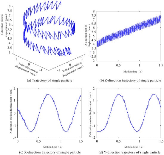
Figure 8.
Single particle motion process under rotary-percussive movement.
Figure 8a shows the trajectory of a single particle. The rock chip particles perform a spiral upward motion in an oscillatory motion. The general trend of the particles is a spiral debris removal motion with a left-handed spiral upward motion, which is related to the rotary motion of the drilling tool, while the fine motion of the particles is an upward and downward oscillating motion along the Z direction, which is related to the impact motion of the drilling tool.
Figure 8b displays the Z direction trajectory of a single particle. The particle’s displacement in the Z direction is linear for time. During the up-and-down vibration, the particles move upwards, covering a distance of approximately 3.5 mm in 1.5 s, from 4 mm to 7.5 mm.
Figure 8c,d display the particles’ trajectories in the X and Y directions. The X direction is sinusoidal, and the Y direction is cosinusoidal. Both directions have a range of motion of ±1.5 mm, which is the diameter of the drilling tool. The X and Y directions are coupled to create a circumferential movement of the particles along the drilling tool.
4.4. Comparison of Rotary Impact Chip Removal and Impact Chip Removal
The rock chip movement under impact motion was analyzed to compare the rock chip delivery of the rotary percussive ultrasonic drilling tool under different motions. Simulation experiments were conducted based on the model presented in the previous section, with rotary motion removed while retaining other parameter settings. The experimental process is shown in Figure 9. The drilling tool does not rotate, and the impact motion is driven by a vibration amplitude of 0.3 mm and a vibration frequency of 50 Hz. The tool has a diameter of 3 mm and a helix angle of lift of 20°. The simulation time was extended to 3 s, and the gravitational acceleration in the simulation environment is 1.63 m2/s. Figure 9a displays the initial state of the particles, with rock chip particles pre-packed in the spiral groove. Following the impact of the drilling tool, rock chip particles are transported and vibrated within the tool. The particles move upwards along the spiral groove, undergoing axial vibratory motion during the spiral conveying process, as demonstrated in Figure 9b–e. The simulation results demonstrate that the ultrasonic drilling tool is capable of discharging rock chips with a single impact. However, the efficiency of chip discharge requires improvement.
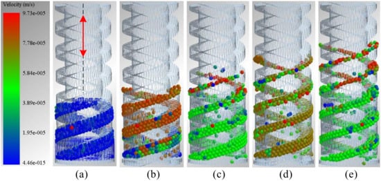
Figure 9.
Chip removal process of drilling tools under percussive movement. (a) The initial state of the particles. (b) Particle state at 0.5 s. (c) Particle state at 1 s. (d) Particle state at 2 s. (e) Particle state at 3 s.
To analyze the movement of rock chip particles during a single impact, a single particle was selected from the rock chip accumulation area. The movement trajectory and speed during impact were analyzed, as shown in Figure 10.
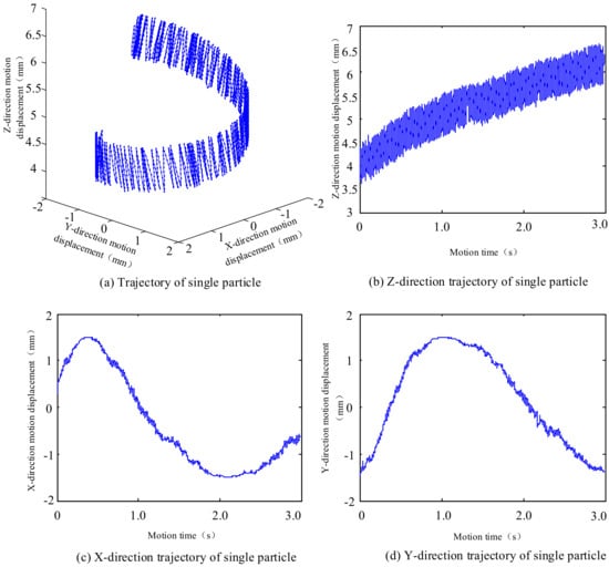
Figure 10.
Single particle motion process under percussive movement.
Figure 10a shows the trajectory of a single particle during oscillatory motion. The rock chip particles spiral upwards during this motion in a right-handed direction, which is only associated with the impact motion of the drilling tool. Figure 10b shows the Z direction trajectory of a single particle. The particle gradually moves upward during the up-and-down oscillation, covering a distance of approximately 2 mm in 3 s, from 4 mm to 6 mm. This upward motion is similar to the rotary percussion motion discussed in the previous section. In comparison to the rotary impact motion chip removal process discussed earlier, the impact motion causes less upward displacement of particles resulting in lower chip removal efficiency.
Figure 10c,d display the trajectories of the particles in the X and Y directions. The X direction follows a sinusoidal pattern, while the Y direction follows a cosine pattern. Additionally, the velocities of the particles in the circumferential direction during impact motion are significantly lower than those of the particles during rotary impact motion.
To evaluate the effectiveness of the drilling tool in transporting rock cuttings, it is necessary to define the transport rate parameter Kre.
In Equation (8),
- Nre: Number of original particles in the rock chip accumulation area;
- Noa: Number of particles transported out of the rock chip accumulation area.
In order to ascertain the veracity of the simulation results, simulation experiments were conducted on the rock cuttings transported by the rotary impact ultrasonic drilling tool under the rotary impact motion, single rotary motion, and single impact motion. In these experiments, the screw angle of the drilling tool was set to 20°, and the ambient gravitational acceleration was 1.63 m2/s. The results of the simulation are presented in tabular form below. The drilling tool’s vibration amplitude was 0.3 mm, with a vibration frequency of 50 Hz and a rotary speed of 120 r/min during the rotary impact chip transport motion. During the impact chip removal motion, the drilling tool vibrates with an amplitude of 0.3 mm and a vibration frequency of 50 Hz, but no rotary motion occurs. In rotary chip removal, the tool rotates at a speed of 120 r/min without any impact movement.
Figure 11 shows the simulation experiments of rotary impact motion, impact motion, and rotary motion chip removal. At the beginning of the simulation experiment (1.1 s), the rotary impact chip removal motion and rotary chip removal motion demonstrated a greater advantage than the impact chip removal motion. Between 1.1 s and 3.0 s, the impact chip removal motion consistently operates at a lower level than the rotary impact motion and rotary motion, which maintains their upward momentum. The oscillation curves of the rotary chip removal motion and rotary impact chip removal motion show similar lowest values. The simulation experiments demonstrate that the rotary impact motion has a higher rock chip transport rate than either the single rotary motion or the single impact motion. The rate at which rock chips are conveyed during rotary impact movement is similar to that of a single rotary movement. However, the rate of rock chip conveyance during single impact movement is significantly lower, making it difficult to convey rock chips promptly using this method.
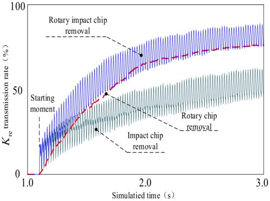
Figure 11.
Contrast of chip removal between rotary-percussive movement, percussive movement, and rotary movement.
4.5. Analysis of the Influence of Drive Parameters on the Chip Removal Process
To assess the impact of individual driving parameters on rock chip transport in ultrasonic drilling, the effect of changing each parameter was calculated separately. The selected parameters include the vibration amplitude and frequency of the drilling tool, the rotary speed of the drilling tool, the ambient gravitational acceleration, and the spiral lift angle of the drilling tool. The impact frequency is 0 Hz, 50 Hz, and 100 Hz. Other simulation system parameters include vibration amplitude of 0 mm, 0.3 mm, and 0.6 mm; rotary speed of 0 r/min, 80 r/min, 160 r/min, and 240 r/min; spiral lift angle of 15°, 20°, and 25°. The gravitational acceleration of the simulation environment is also given as 0 m2/s, 1.63 m2/s, and 3.26 m2/s. Table 2 shows the neutral parameters of the single-parameter analysis simulation.

Table 2.
Neutral parameters of single-parameter analysis simulation model.
Figure 12 shows the results of simulation experiments on the chip transport rates of drilling tools under different impact frequencies. At 0 Hz, the drilling tool relies solely on rotary motion to transport chips, resulting in a flat curve without oscillation. As the impact frequency increases from 0 Hz to 100 Hz, the transport rate (Kre) increases gradually and stepwise. During the transition from 1.0 s to 2.0 s, the transport rate (Kre) increases at a faster rate, while during the transition from 2.0 s to 3.0 s, the transport rate (Kre) increases at a slower rate.
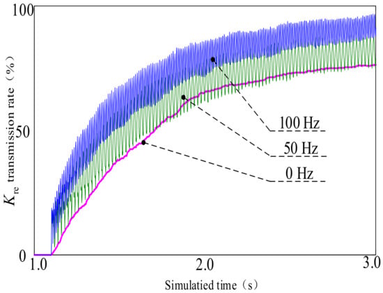
Figure 12.
Contrast test of drilling tool chip removal under different percussive frequencies.
Figure 13 shows the results of simulation experiments on the chip transport rate of drilling tools at different impact amplitudes. Similar to the 0 Hz impact frequency case, at 0 mm, the drilling tool relies solely on rotary motion to transport chips, resulting in a smooth upward curve for the conveying rate. As the impact amplitude increases from 0 mm to 0.6 mm, the conveying rate (Kre) increases sequentially. The conveying rate (Kre) increases rapidly before 2.0 s and then increases slowly after 2.0 s.

Figure 13.
Contrast test of drilling tool chip removal under different percussive amplitude.
Figure 14 shows the results of simulation experiments on the chip conveyance rates of drilling tools at different rotary speeds. The conveying rate (Kre) increases from 40% to 85% when the rotary speed of the drilling tool is changed from 0 r/min to 240 r/min, which is the largest increase in conveying rate observed in the simulation experiments.
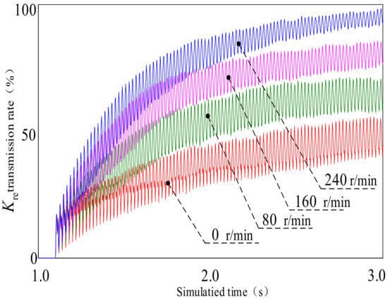
Figure 14.
Contrast test of drilling tool chip removal under different rotational speed.
The three sets of simulation experiments above demonstrate that the conveying rate is higher at impact frequencies of 50 Hz and 100 Hz compared to 0 Hz. Additionally, the conveying rate is higher at impact amplitudes of 0.3 mm and 0.6 mm compared to 0 mm. Finally, the conveying rate is higher when the rotary rotation speed is between 80 r/min and 240 r/min compared to 0 r/min. The three sets of simulation experiments demonstrate that the rotary percussive ultrasonic drill’s rotary impact chip removal has a higher conveying rate than the single rotary chip removal and single impact movement.
The rate at which drilling tools convey chips is greatly influenced by the ambient gravity acceleration. Figure 15 shows the results of simulation experiments on chip conveying rates under different ambient gravity accelerations. As demonstrated in the figure, as the ambient gravitational acceleration increases from 0 m2/s to 3.26 m2/s, the conveying rate (Kre) decreases sequentially. Under low gravitational acceleration, particles produce greater vibration velocity and displacement due to impact motion, which improves the efficiency of rock chip conveyance. At zero ambient gravitational acceleration, the transport rate of chips in the drilling tool remains high in the later stages.
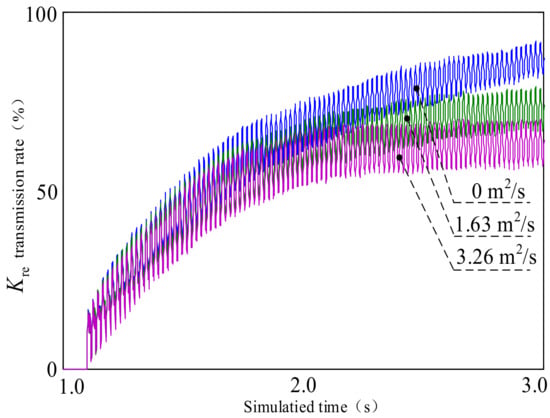
Figure 15.
Contrast test of drilling tool chip removal under different gravitational acceleration.
Figure 16 shows a comparison of the chip conveyance rates of drilling tools with different helical lift angles. The simulation experiment kept the diameter of the drilling tool of the rotary percussion ultrasonic drill constant while changing the screw-up angle of the drilling tool to three values of 15°, 20°, and 25°. The chip transport rate of the tool increased as the tool helix angle changed from 15° to 25°. During the period of 1.0 s to 2.0 s, the conveyance rate was faster at a 25° tool spiral lift angle.
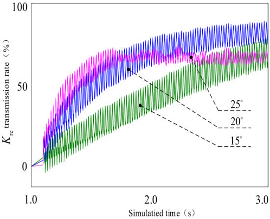
Figure 16.
Contrast test of drilling tool chip removal under the different angles of the drilling tool.
5. Analysis of the Effect of Drive Parameters on Transport Based on Taguchi Orthogonal Experiments
5.1. Design of Taguchi Orthogonal Experiments
The process of removing chips in the rotary percussive ultrasonic drill is influenced by various factors, including the vibration amplitude and frequency of the drilling tool, the rotary speed of the tool, the ambient gravitational acceleration, and the spiral lift angle of the tool. The previous section analyzed the influence of each parameter. However, to examine the mutual coupling relationship of each parameter on the chip removal of the drilling tool and the order of the influence degree, a systematic experimental study is necessary.
The study selected five factors to investigate: vibration amplitude, vibration frequency, rotary speed, ambient gravitational acceleration, and spiral uplift angle of drilling tools. Each factor was tested at three different levels. A full-scale experiment can accurately assess the relationship between experimental factors and the effects of parameter interaction. However, the number of experiments required for a full-scale experiment is often too high. Orthogonal experimentation is a scientific method used to study the mutual influence relationship between multiple factors and levels. It can effectively reduce the number of full-scale experiments by relying on a representative part of the experiment to replace the full-scale experiment.
The Taguchi orthogonal method was used to investigate the impact of parameters on chip removal in a rotary percussive ultrasonic drill system. According to the standard orthogonal table, the L27 (35) orthogonal table was selected, in which 3 indicated that the experimental level was three and 5 represented that the experimental factors were five; the orthogonal experiment had a total of 27 groups. The experimental factors and levels are shown in Table 3.

Table 3.
Factors and levels of chip removal test.
The selected experimental factors and levels were as follows: factor–vibration amplitude of the drilling tool (mm), levels of 0, 0.3, 0.6; factor–vibration frequency of the drilling tool (Hz), levels of 0, 50, 100; factor–rotary speed of the drilling tool (r/min), levels of 0, 120, 240; factor–ambient gravitational acceleration (m/s2), levels of 0, 1.63, 3.26; factor–drilling tool helical lift angle (°), horizontal 15, 20, 25.
Table 4 shows the design scheme of the orthogonal experiment which consists of 27 experiments. The five parameters are varied sequentially according to the orthogonal law, and each group of parameters in the horizontal direction represents one experiment. The first value in the table indicates the experimental level, while the value in parentheses represents the actual parameter.

Table 4.
Design scheme of orthogonal experiment.
5.2. Taguchi Analysis of Results of Orthogonal Experiments
To ensure the reliability of the experimental results, each group of experiments was conducted three times and the results were averaged. Table 5 presents the rock chip delivery rate of the rotary percussion ultrasonic drill for all 27 experiments conducted according to the protocols arranged in Table 4, including the three experiments mentioned.

Table 5.
Orthogonal test results.
Through analysis of data from orthogonal experiments on the delivery rate of ultrasonic drilling tools under different parameters, the range value of the experimental results and the order of the range of each parameter on the delivery rate can be obtained. Table 6 shows the results of the orthogonal experiment. The experimental factors were of the same level, and K = (where pi is the delivery rate of the i-th experiment). The previous groups of experimental results were selected based on this calculation, and the average of each factor at the same level was then calculated.

Table 6.
Factor response table.
The range value is indicative of the extent to which the final results are influenced by changes in the level of the experimental factor. A high range value suggests that the selected level value under the factor exerts a considerable influence on the efficiency of the ultrasonic drilling rig. The factor with the highest value of range is that which exerts the greatest influence on the final result. In other words, it is the main factor affecting the drilling tool delivery rate.
The optimal parameters influencing the conveyance rate of rotary percussion ultrasonic drilling were ultimately derived from the outcomes of Taguchi orthogonal experiments, as illustrated in Table 7.

Table 7.
The optimal parameter table.
6. Discussion
- (1)
- The study analyzed the motion state of rock chips during the process of chip removal from drilling tools based on the theories of spiral conveying and vibratory conveying. A motion model of rock chip microelements was established, and the influence of drilling tool driving parameters on the effective chip removal speed was examined.
- (2)
- A simulation model for rock chip particles was established using the discrete element method, and parameter matching between rock chip particles and simulated particles was completed by adjusting the parameters of the HMB with an adhesive contact model. The simulation model was then used to analyze the chip removal motion of the drilling tool under rotary impact and the influence of driving parameters on the chip removal process. Compared to single rotary or single impact chip removal, rotary impact chip removal has the highest rate of rock chip transport.
- (3)
- The study analyzed the influence of drilling tool driving parameters on the rock cuttings conveying rate using Taguchi orthogonal experiments. An orthogonal experimental scheme was designed to complete the analysis of the interaction effect of each parameter. The delivery rate of the rotary percussion ultrasonic drilling tool is influenced by several driving parameters. These parameters, in order of importance, are rotary speed, vibration amplitude, vibration frequency, helix angle of lift, and ambient gravitational acceleration. The rotary speed of the drilling tool is approximately eight times greater than the degree of influence of ambient gravitational acceleration on the delivery rate.
- (4)
- In the future, an investigation into the influence of the structural parameters of the ultrasonic drilling tool on the conveying rate may be conducted, with a view to optimising the parameters of the ultrasonic drilling tool. Furthermore, the impact of these parameters on the conveying rate can be investigated by refining the simulation methodology, extending the simulation duration, and enhancing the experimental approach.
Author Contributions
Conceptualization, Y.W. and W.Z.; Methodology, Y.W.; Software, D.Z. and Z.Y.; Validation, W.Z. and L.Z.; Formal analysis, G.T. and S.Y.; Investigation, D.Z.; Resources, Z.Y.; Data curation, Y.W., G.T. and S.Y.; Writing—original draft, Y.W., D.Z. and Z.Y.; Writing—review and editing, W.Z., W.Z. and L.Z.; Visualization, G.T.; Supervision, S.Y.; Project administration, Y.W., W.Z. and L.Z.; Funding acquisition, Y.W., W.Z. and L.Z. All authors have read and agreed to the published version of the manuscript.
Funding
The authors thank the anonymous reviewers for their critical and constructive review of the manuscript. This project is financially supported by fundamental research funds for National Natural Science Foundation of China (No. 52005349). Liaoning Provincial Department of Education Project—Basic Research Business Fund Special Project (Youth Project).
Data Availability Statement
The data that support the findings of this study are available from the corresponding authors upon reasonable request.
Conflicts of Interest
The authors declare no conflicts of interest. The funders had no role in the design of the study; in the collection, analyzes, or interpretation of data; in the writing of the manuscript; or in the decision to publish the results.
References
- Zacny, K.; Bar-Cohen, Y.; Brennan, M.; Briggs, G.; Cooper, G.; Davis, K.; Dolgin, B.; Glaser, D.; Glass, B.; Gorevan, S.; et al. Drilling systems for extraterrestrial subsurface exploration. Astrobiology 2008, 8, 665–706. [Google Scholar] [CrossRef] [PubMed]
- Bar-Cohen, Y.; Zacny, K. (Eds.) Drilling in Extreme Environments: Penetration and Sampling on Earth and Other Planets; John Wiley & Sons: Weinheim, Germany, 2009. [Google Scholar]
- Zacny, K.; Wilson, J.; Chu, P.; Craft, J. Prototype rotary percussive drill for the Mars sample return mission. In Proceedings of the 2011 IEEE Aerospace Conference, AERO’11, Big Sky, MT, USA, 5–12 March 2011. [Google Scholar]
- Finzi, A.E.; Zazzera, F.B.; Dainese, C.; Malnati, F.; Magnani, P.G.; Re, E.; Bologna, P.; Espinasse, S.; Olivieri, A. SD2-How to sample a comet. Space Sci. Rev. 2007, 128, 281–299. [Google Scholar] [CrossRef]
- Richardson, J.E.; Steckloff, J.K.; Minton, D.A. Impact-produced seismic shaking and regolith growth on asteroids 433 Eros, 2867 Šteins, and 25143 Itokawa. Icarus 2020, 347, 113811. [Google Scholar] [CrossRef]
- Landis, M.; Castillo-Rogez, J.; Hayne, P.; Hsieh, H.; Hughson, K.; Kubitschek, D.; Miller, K.; Prettyman, T.; Rivkin, A.; Schmidt, B.; et al. The case for a Themis asteroid family spacecraft mission. Planet. Space Sci. 2022, 212, 105413. [Google Scholar] [CrossRef]
- Nakamura, T.; Matsumoto, M.; Amano, K.; Enokido, Y.; Zolensky, M.E.; Mikouchi, T.; Genda, H.; Tanaka, S.; Zolotov, M.Y.; Kurosawa, K.; et al. Formation and evolution of carbonaceous asteroid Ryugu: Direct evidence from returned samples. Science 2022, 379, eabn8671. [Google Scholar] [CrossRef]
- Zhang, T.; Zhang, W.; Wang, K.; Gao, S.; Hou, L.; Ji, J.; Ding, X. Drilling, sampling, and sample-handling system for China’s asteroid exploration mission. Acta Astronaut. 2017, 137, 192–204. [Google Scholar] [CrossRef]
- Zhang, X.; Zhang, G.; Xie, H.; Gao, M.; Wen, Y. A review of sampling exploration and devices for extraterrestrial celestial bodies. Space Sci. Rev. 2022, 218, 59. [Google Scholar] [CrossRef]
- Zhang, Y.; Zhang, T.; Wei, H.; Liu, J.; Wang, W.; Yuan, X.; Pang, Y.; Guan, Y.; Hou, X.; Xu, K. Advances in extraterrestrial drilling technology to discover the secrets hidden inside celestial bodies. Space Sci. Rev. 2022, 218, 47. [Google Scholar] [CrossRef]
- Ding, X.L.; Li, K.J.; Yin, Z.W. Multi-rod deep drill for lunar subsurface sampling. J. Astronaut. 2009, 30, 1189–1194. (In Chinese) [Google Scholar]
- Harkness, P.; Lucas, M. A brief overview of space applications for ultrasonics. Ultrasonics 2012, 52, 975–979. [Google Scholar] [CrossRef]
- Bao, X.; Bar-Cohen, Y.; Chang, Z.; Dolgin, B.; Sherrit, S.; Pal, D.; Du, S.; Peterson, T. Modeling and computer simulation of ultrasonic/sonic driller/corer (USDC). IEEE Trans. Ultrason. Ferroelectr. Freq. Control. 2003, 50, 1147–1160. [Google Scholar] [PubMed]
- Bar-Cohen, Y.; Sherrit, S.; Dolgin, B.P.; Bridges, N.; Bao, X.; Chang, Z.; Yen, A.; Saunders, R.S.; Pal, D.; Kroh, J.; et al. Ultrasonic/sonic driller/corer (USDC) as a sampler for planetary exploration. In Proceedings of the 2001 IEEE Aerospace Conference, Big Sky, MT, USA, 10–17 March 2001; SPIE Press: Bellingham, WA, USA, 2012; pp. 263–271. [Google Scholar]
- Thomas, P.N.H. Magna Parva and ESA’s ultrasonic drill tool for planetary surface exploration. In Earth and Space 2010: Engineering, Science, Construction, and Operations in Challenging Environments; American Society of Civil Engineers: Reston, VA, USA, 2010; pp. 1235–1245. [Google Scholar]
- Timoney, R.; Harkness, P.; Li, X.; Bolhovitins, A.; Cheney, A.; Lucas, M. The development of the European ultrasonic planetary core driller (UPCD). In Proceedings of the AIAA SPACE 2015 Conference and Exposition (AIAA-2005-4553), Pasadena, CA, USA, 31 August–2 September 2015; AIAA: Reston, VA, USA, 2015. [Google Scholar]
- Li, X.; Worrall, K.; Harkness, P.; Timoney, R.; Bolhovitins, A.; Lucas, M. A motion control system design for an ultrasonic planetary core driller (UPCD) unit. In Proceedings of the AIAA SPACE 2015 Conference and Exposition (AIAA-2015-4554), Pasadena, CA, USA, 31 August–2 September 2015; AIAA: Reston, VA, USA, 2015. [Google Scholar]
- Yang, K. Research on Drilling Corer Based on Ultrasonic/Acoustic Energy Coupling Mechanism. Ph.D. Thesis, Nanjing University of Aeronautics & Astronautics, Nanjing, China, 2012; pp. 1–58. (In Chinese). [Google Scholar]
- Quan, Q.Q.; Li, H.; Deng, Z.J.; Wang, X.; Jiang, S.Y. An ultrasonic coring tool for rock-sampling on extraterrestrial planets. J. Cent. South Univ. Sci. Technol. 2016, 47, 4081–4089. (In Chinese) [Google Scholar]
- Potthast, C.; Twiefel, J.; Wallaschek, J. Modeling approaches for an ultrasonic percussion drill. J. Sound Vib. 2007, 308, 405–417. [Google Scholar] [CrossRef]
- Cardoni, A.; Harkness, P.; Lucas, M. Ultrasonic rock sampling using longitudinal-torsional vibrations. Phys. Procedia 2010, 3, 123–134. [Google Scholar] [CrossRef]
- Harkness, P.; Lucas, M.; Cardoni, A. Coupling and degenerating modes in longitudinal–torsional step horns. Ultrasonics 2012, 52, 980–988. [Google Scholar] [CrossRef]
- Sashida, T. Trial construction and operation of an ultrasonic vibration driven motor: Theoretical and experimental investigation of its performances. Oyo Buturi 1982, 51, 713–720. [Google Scholar]
- Kumada, A.A. piezoelectric ultrasonic motor. Jpn. J. Appl. Phys. 1985, 24, 739–741. [Google Scholar] [CrossRef]
- Tsujino, J.; Takeuchi, M.; Koshisako, H. Ultrasonic rotary motor using a longitudinal-torsional vibration converter. In Proceedings of the IEEE Ultrasonic Symposium, Tucson, AZ, USA, 20–23 October 1992; pp. 887–892. [Google Scholar]
- Tsujino, J.; Suzuki, R.; Yasoima, H. Load characteristics of ultrasonic rotary motor using a longitudinal-torsional vibration converter. In Proceedings of the IEEE Ultrasonics Symposium, San Antonio, TX, USA, 3–6 November 1996; pp. 377–382. [Google Scholar]
- Tsujino, J.; Suzuki, R.; Takeuchi, M. Load characteristics of ultrasonic rotary motor using a longitudinal-torsional vibration converter with diagonal slits. Large Torque Ultrasonic Rotary Motor. Ultrasonic 1996, 34, 265–269. [Google Scholar] [CrossRef]
- Tsujino, J.; Ueoka, T.; Otoda, K.; Fujimi, A. One-dimensional longitudinal-torsional vibration converter with multiple diagonally silted parts. Ultrasonics 2000, 38, 72–76. [Google Scholar] [CrossRef]
- Tsujino, J.; Suzuki, A. Load characteristics of ultrasonic motor with a longitudinal-torsional converter and various nonlinear springs for inducing static pressure. In Proceedings of the IEEE Ultrasonics Symposium 2001, Atlanta, GA, USA, 7–10 October 2001; pp. 545–550. [Google Scholar]
- Park, T.-G.; Jeong, D.-S.; Kim, M.-H.; Song, T.-K. A study on the rotary-type ultrasonic motor using a longitudinal torsional vibration converter. Mater. Chem. Phys. 2006, 98, 1–4. [Google Scholar] [CrossRef]
- Yang, L.; Jin, J.M.; Zhao, C.S. An Ultrasonic Rotary Motor by Using Longitudinal-Torsional Vibration Converter with Holes. J. Vib. Meas. Diagn. 2009, 29, 133–136. [Google Scholar]
- Yang, L.; Zhao, C.S.; Zhang, J.H. Vibration Analysis and Characteristics of Ultrasonic Motor Using a Longitudinal-torsional Convertor With Oblique Slots. J. Beijing Univ. Technol. 2010, 36, 870–875. [Google Scholar]
- Yang, L.; Ding, Q.J.; Zhao, C.S. Load Characteristics of Ultrasonic Motor Using Longitudinal-torsional Convertor With Diagonal Slits Under Various Friction Pairs. Proc. CSEE 2010, 30, 94–98. [Google Scholar]
- Badescu, M.; Bar-Cohen, Y.; Sherrit, S.; Bao, X.; Chang, Z.; Ostlund, P.; Aldrich, J. Percussive augmenter of rotary drillers(PARoD). In Proceedings of the SPIE Smart Structures and Materials Nondestructive Evaluation and Health Monitoring, San Diego, CA, USA, 10–14 March 2013; SPIE Press: Bellingham, WA, USA, 2013; pp. 1–8. [Google Scholar]
- Sherrit, S.; Domm, L.; Bao, X.; Bar-Cohen, Y.; Chang, Z.; Badescu, M. Single piezo-actuator rotary-hammering (SPaRH) driller. In Proceedings of the of SPIE Smart Structures and Materials Nondestructive Evaluation and Health Monitoring, San Diego, CA, USA, 11–15 March 2012; SPIE Press: Bellingham, WA, USA, 2012; pp. 1–11. [Google Scholar]
- Wang, Y.C. Research on Rotary Percussive Ultrasonic Drill Driven by Single Piezoelectric Stack. HIT. 2019. Available online: https://chn.oversea.cnki.net/kcms/detail/detail.aspx?filename=1019645628.nh&dbcode=CDFD&dbname=CDFDLAST2020&uniplatform=NZKPT (accessed on 6 October 2024).
- Wang, Y.C.; Quan, Q.Q.; Yu, H.Y. A rotary-percussive ultrasonic drill driven by single piezoelectric stack. J. Beijing Univ. Aeronaut. Astronaut. 2018, 44, 1850–1859. [Google Scholar]
- Godwin, R.J. A review of the effect of implement geometry on soil failure and implement forces. Soil Tillage Res. 2007, 97, 331–340. [Google Scholar] [CrossRef]
- Hong, W. Modeling, Estimation, and Control of Robot-Soil Interactions. Ph.D. Thesis, Massachusetts Institute of Technology, Cambridge, MA, USA, 2001. [Google Scholar]
- Cundall, P.A. UDEC-A Generalised Distinct Element Program for Modelling Jointed Rock; Cundall (PETER) Associates: Newcastle Upon Tyne, UK, 1980. [Google Scholar]
- Donzé, F.V. Impacts on Cohesive Frictional Geomaterials: A Dem Analysis Applied to Concrete. Eur. J. Environ. Civ. Eng. 2008, 12, 967–985. [Google Scholar] [CrossRef]
- Shen, Y. Research on the Impact Type Penetrator and Its Mechanical Properties during Penetrating Lunar Regolith Profile. HIT. 2017. Available online: https://d.wanfangdata.com.cn/thesis/ChhUaGVzaXNOZXdTMjAyNDA5MjAxNTE3MjUSCUQwMTU4OTI5ORoIb2d2MXI0eWU%253D (accessed on 6 October 2024).
- Zhao, D.M. Research on Lunar Soil Chip Removing Model and Lunar Subsurface Coring Drill. HIT. 2016. Available online: https://d.wanfangdata.com.cn/thesis/ChhUaGVzaXNOZXdTMjAyNDA5MjAxNTE3MjUSCUQwMTMzMjI4MxoIdjU2bWxpMm0%253D (accessed on 6 October 2024).
Disclaimer/Publisher’s Note: The statements, opinions and data contained in all publications are solely those of the individual author(s) and contributor(s) and not of MDPI and/or the editor(s). MDPI and/or the editor(s) disclaim responsibility for any injury to people or property resulting from any ideas, methods, instructions or products referred to in the content. |
© 2024 by the authors. Licensee MDPI, Basel, Switzerland. This article is an open access article distributed under the terms and conditions of the Creative Commons Attribution (CC BY) license (https://creativecommons.org/licenses/by/4.0/).