Article

Integrated Guidance and Control for Collision Course Stabilization of Dual-Controlled Interceptors

1
Department of Mechanical Engineering, Incheon National University, Incheon 22012, Republic of Korea
2
Department of Safety Engineering, Incheon National University, Incheon 22012, Republic of Korea
*
Author to whom correspondence should be addressed.
Aerospace 2024, 11(1), 9; https://doi.org/10.3390/aerospace11010009
Submission received: 4 December 2023 / Revised: 15 December 2023 / Accepted: 20 December 2023 / Published: 21 December 2023
(This article belongs to the Section Aeronautics)

Abstract

:
We propose an integrated guidance and control law for dual-controlled interceptor dynamics controlled via tail-fin deflection and reaction jets. Because dual-controlled interceptors have two input channels in each axis, we define two error variables as the first step to derive an integrated controller. One variable is configured as a line-of-sight rate for nullifying heading errors to a target, and the other is established to allocate the control strategy for the fast response of an integrated loop. Consequently, interceptor dynamics are controlled to produce a required maneuver by the net force of the two control inputs when a large heading error occurs, thereby accelerating the control response compared with conventional control methods. After the heading error is sufficiently reduced, it is switched to a general control strategy that performs a maneuver through the lift generated by the fuselage angle of attack to prevent excessive use of the control inputs. Based on such a control strategy, the proposed integrated law is expected to exhibit enhanced homing performance compared with existing control methods that perform guidance and control in separate loops. Moreover, numerical simulations considering engagement scenarios with highly maneuverable targets are conducted to evaluate the performance of the proposed integrated guidance and control law.

1. Introduction

General aerodynamic-driven interceptors are operated to produce a required maneuver based on attitude control by tail or canard wings [1]. Compared with the control method of canard deflection, the control method of tail-fin deflection is more effective in generating aerodynamic lift for a maneuver because tail wings can commonly be located far from the center of mass of an interceptor body. However, owing to the inherent characteristics of tail-controlled interceptors, where their aerodynamic lift generated by a tail-wing and fuselage is in opposite directions, a non-minimum phase that makes the controller design difficult arises [2,3,4,5]. In addition, at high altitudes, it is difficult for tail-wings to produce sufficient control inputs because of low dynamic pressure, which deteriorates the performance of interceptors.
To overcome such limitations of the aerodynamic-driven interceptors, propulsive actuator systems that induce jet propulsion in a direction of a required maneuver, called reaction jets, can be used together with tail-fin actuators for agile interceptors. Interceptors that perform required maneuver using aerodynamic tail-fins and reaction jets are called dual-controlled interceptors. Because reaction jets are commonly located between the center of mass and warhead in interceptor bodies, the generated propulsive force is in the same direction as the required maneuver; thus, the difficulty in designing an autopilot due to a non-minimum phase is significantly alleviated. Compared with aerodynamic-only-controlled interceptors, dual-controlled interceptors can realize a relatively fast response speed regardless of altitude.
Various studies have been conducted on dual-controlled interceptors to improve the control performance of autopilots [6,7,8,9,10]. The methodology presented in [6] uses a variable control structure technique based on the combination of aerodynamics and propulsive controls to achieve a high angle-of-attack (AOA) maneuver. In [7], a multiple-input multiple-output (MIMO) control system was designed to employ the blended control of aerodynamic fins and reaction jets. Using the coefficient diagram method, an autopilot was designed as the composition of feedback control via aerodynamic control and feedforward control via reaction jet control. In [8], a solution that minimizes the rate of change in control inputs was obtained by applying the standard linear quadratic regulator (LQR) to the linearized dynamics of a dual-controlled interceptor. An allocation algorithm that minimizes the use of reaction jets at the steady state was also proposed for allocation optimization. In [9], a nonlinear blending principle of reaction jets and tail-fins was established. Stable internal dynamics were ensured by controlling the pitch rate so that maneuvering acceleration is produced by the fuselage AOA. By further developing a strategy to control the pitch rate, a blending principle of tail-fins and reaction jets was established to maximize the response speed [10]. The aforementioned control methods for dual-controlled interceptors, presented in [6,7,8,9,10], use two control channels of inputs per axis to track the guidance command and perform additional tasks, such as attitude stabilization, optimal input allocation, and response speed maximization. In a previous study [10], a control technique that can significantly enhance the tracking performance for maneuver acceleration by actively using changes in dynamic characteristics according to the control allocation of aerodynamic fins and reaction jets was proposed. This technique, which improves the control performance based on the dynamic characteristics of dual-controlled interceptors, could be more useful when a guidance loop is integrated. Therefore, in this study, we enhance the interception accuracy by expanding such a technique to an integrated guidance and control loop.
Conventional autopilot algorithms for interceptor operation are generally configured with separate loops for guidance and flight control; the latter tracks the desired acceleration command produced by the former. This approach of separated design has the obvious advantages of facilitating the design of each loop and easy practical implementation. However, because there is a time delay between the separated loops, rapid changes in system states could cause instability in the entire loop. Although several studies have considered incorporating the flight control loop into the guidance loop by considering autopilot dynamics as a simple time delay system [11,12], this solution is inadequate because of unexpected changes in state variables that are not considered.
To address such issues completely, it is necessary to integrate guidance and control loops considering all state variables. An integrated design for the guidance and flight control loops using all variables can have various benefits, such as improving the stability of the entire loop. The integrated controllers presented in [13,14] are designed to regulate the zero-effort miss, which denotes the expected miss distance if two players no longer perform normal maneuvers, using the sliding mode control technique. In particular, the integrated method reported in a previous study [14] was developed to be applicable to dual-controlled interceptors controlled by two aerodynamic surfaces: Canard and tail controls. Numerical computation approaches such as the state-dependent Riccati equation methodology and strength Pareto evolutionary algorithm have also been employed to develop integrated control loops [15,16]. These approaches involve obtaining optimal solutions using numerical algorithms. In [17], an adaptive nonsingular terminal sliding mode control method was developed for a class of nonlinear systems that consider disturbances and uncertainties. By guaranteeing finite-time convergence, the proposed method was incorporated into the design of an integrated guidance and control loop. In [18], output tracking continuous-time predictive control was employed to design an integrated autopilot guidance loop. In [19], an integrated guidance and control loop structure was developed for tail-controlled interceptors. The structure is similar to the conventional three-loop configuration used for various tail-controlled flight systems.
Notably, the integrated controller presented in [14] was designed for dual-controlled interceptor dynamics. Using an additional degree of freedom in control inputs, the AOA and tail-fin contributions to pitch moment were reduced by properly defining a sliding manifold. However, the integrated controller was designed for only aerodynamic-driven interceptors controlled by tail-fins and canards, so it may not apply to dual-controlled interceptors involving reaction jets. Further, it was not designed so that the degree of freedom, which is added to the control loop, directly contributes to the guidance performance; thus, a definite performance improvement by loop integration may not be guaranteed.
In this study, we propose an integrated guidance and control law for dual-controlled interceptor dynamics controlled by aerodynamic tail-fins and reaction jets. As the first step to designing an integrated controller, two error variables are established: one variable is defined as the line-of-sight (LOS) rate for homing, and the other is configured to allocate the fast response control strategy of the integrated loop. A sliding mode control is adopted to regulate the error variables to build a controller robust to disturbances and uncertainties. As a result, the integrated autopilot makes interceptors generate a required maneuver by the net force of two control inputs when the heading error is large, which increases the response speed compared with conventional controllers. After the heading error is sufficiently reduced, it transitions to a general strategy that maneuvers through aerodynamic lifts to avoid excessive use of the control inputs. Using such a control strategy, the proposed integrated controller should exhibit enhanced homing performance compared with conventional separated loop-based methods. This transition strategy is motivated by previous studies: [10,20]. In particular, this study is based on the transition control concept introduced in [10] and includes demonstrative results compared with investigations in [20].
The remainder of this article is organized as follows. In Section 2, the engagement kinematics and interceptor dynamics are formulated as the groundwork for developing an integrated controller. In Section 3, an integrated controller for guidance and autopilot loops is proposed based on a control structure that shifts strategies according to heading errors. The performance of the proposed controller is assessed via numerical simulations in Section 4, and concluding remarks are presented in Section 5.

2. Problem Statement

In this section, engagement kinematics and an interceptor configuration are formulated as the groundwork to develop an integrated controller. The engagement is assumed to be conducted in a two-dimensional plane, and the interceptor configuration is treated as the longitudinal dynamics of an interceptor that uses a tail-fin deflection and reaction jet. Then, both dynamics are combined without linearization to derive an integrated guidance and control.

2.1. Engagement Kinematics

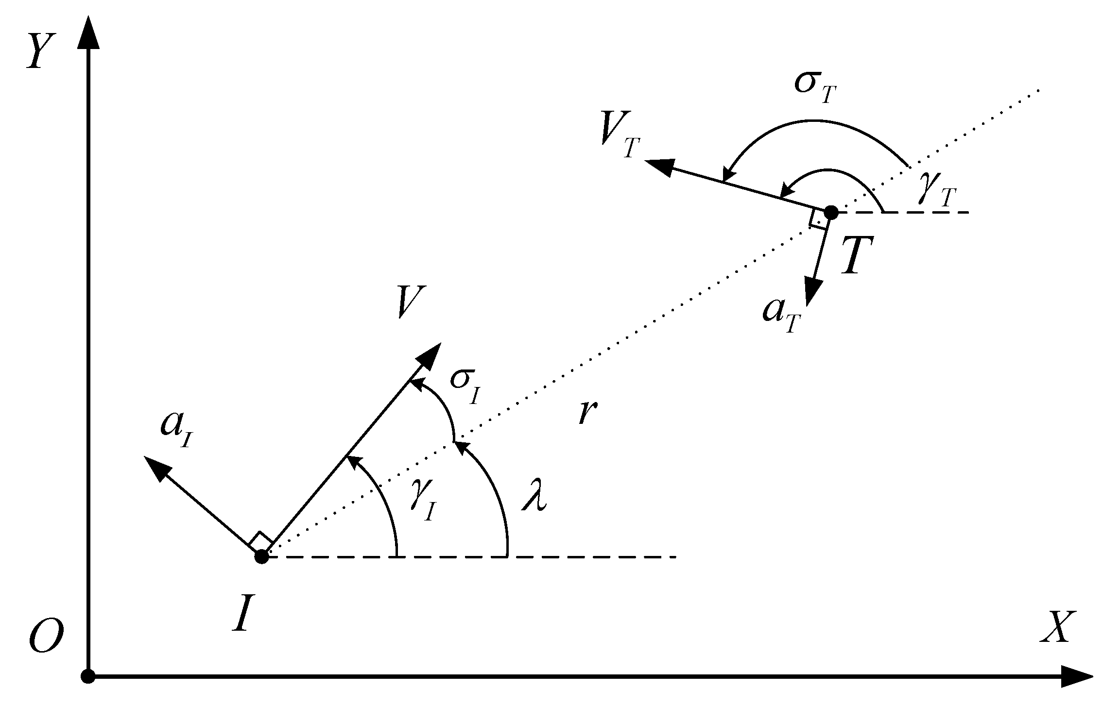
Consider a planar engagement geometry in which the interceptor, I, pursues a maneuvering target, T (Figure 1). Each player moves at a speed of V ( · ) and performs maneuvers with a normal acceleration of a ( · ) . The relative range and LOS angle between both players are represented by r and λ , respectively. Thus, the engagement kinematics are expressed as the following system of nonlinear differential equations:
r ˙ = V T cos γ T λ V I cos γ I λ
r λ ˙ = V T sin γ T λ V I sin γ I λ
where γ I and γ T denote the flight path angles of the interceptor and target, respectively. They are governed by the normal acceleration of each one as follows:
γ ˙ I = a I V I , γ ˙ T = a T V T
Subscripts I and T denote the interceptor and target, respectively. In the end game, the engagement is terminated when the closing velocity r ˙ is greater than or equal to zero; that is, r ˙ is assumed to be negative during the end game.
Figure 1. Two-dimensional engagement geometry for a maneuvering target.
Aerospace 11 00009 g001

2.2. Interceptor Dynamics

An interceptor model in the longitudinal plane is assumed to be controlled by two inputs: the tail-fin and reaction jet. The short-period equations of the longitudinal interceptor dynamics are given by
α ˙ = q + a z cos α + g cos γ I V I = q + Q S m V I C z α α + C z δ δ z + 1 m V I T z cos α + g V I cos γ I
q ˙ = M y I y y = Q S d I y y C m α α + C m q d 2 V q + C m δ δ z l t I y y T z
where α , q, a z , M y , δ z , and T z denote the AOA, pitch rate, z-axis acceleration, net moment with respect to the y axis, tail-fin deflection, and reaction jet thrust, respectively. V I , Q, m, S, d, I y y , and l t denote the speed, dynamic pressure, mass, reference area, reference length, moment of inertial with respect to the pitch axis, and length between the reaction jet and interceptor center of mass, respectively, C z α and C z δ denote the aerodynamic derivatives of the z-axis force with respect to the AOA and tail-fin deflection, respectively, and C m α , C m q , and C m δ denote the pitch moment derivatives with respect to the AOA, pitch rate, and tail-fin deflection, respectively. The aerodynamic coefficients are assumed to be variables determined according to various flight conditions, such as altitude and Mach number.

2.3. Integrated Dynamics

The engagement kinematics and interceptor dynamics, defined as (1)–(5), can be integrated by the angular relation θ = α + γ I , where θ denotes the Euler angle for the pitch axis. Because θ has the dynamics of θ ˙ = q in the longitudinal plane, we can rewrite the equations for γ I in (3) as follows:
γ ˙ I = 1 m V I Q S C z α α + C z δ δ z + T z cos α g cos γ I V I .
Additionally, most target-pursuing guidance laws adopt a strategy of making λ ˙ converge to zero to achieve a collision course for the designated target. As such, we combine (2) and (6) to derive the equations for λ ˙ as follows:
r λ ¨ = 2 r ˙ λ ˙ + Q S C z α α + C z δ δ z + T z m cos α + g cos γ I cos γ I λ + a T cos γ T λ
Combining (2)–(7), we have the integrated equations for the engagement kinematics and interceptor dynamics as follows:
x ˙ = f + G u + Δ f
The state and input vectors, x and u, respectively, are defined as follows:
x = λ λ ˙ α q T , u = δ z T z T
and the system vector f, matrix G, and disturbance term Δ f are given by
f = λ ˙ 2 r ˙ λ ˙ / r + Q S C z α α cos α cos γ I λ / m r + g cos γ I cos γ I λ / r q + Q S C z α α / m V I + g cos γ I / V I Q S d C m α α + C m q d / 2 V I q / I y y , G = 0 0 Q S C z δ cos α cos ( γ I λ ) / m r cos α cos ( γ I λ ) / m r Q S C z δ / m V I 1 / m V I Q S d C m δ / I y y l t / I y y , Δ f = 0 a T cos ( γ T λ ) / r Δ α Δ q
where Δ α and Δ q denote the modeling errors arising from aerodynamic uncertainties, unexpected disturbances, etc.

3. Integration of Guidance and Autopilot Loops

In this section, we propose an integrated controller based on the combined dynamics presented in (8)–(10). Sliding manifolds for satisfying realistic requirements are defined in Section 3.1, and the integrated controller is established so that the sliding manifolds are achieved in Section 3.2.

3.1. Sliding Manifolds

Dual-controlled interceptor dynamics have two degrees of freedom for control in each axis, indicating that two sliding manifolds can be achieved by applying the sliding mode control method. The first sliding manifold is defined so that the target interception is satisfied. During the general one-on-one engagement scenario, the interceptor can satisfy the requirement of the collision course against a target if the relative velocity component perpendicular to the LOS becomes zero. Because the component perpendicular to the LOS is defined as V λ r λ ˙ , we set the first sliding manifold as follows:
s 1 = λ ˙
In general pursuit-evasion problems for simple mass points, it is sufficient to achieve target interception if an interceptor is controlled to achieve the manifold of s 1 = 0 . However, in realistic applications, the accomplishment of s 1 = 0 is insufficient for ensuring stable target interception because the interceptor attitude is not guaranteed to be stabilized.
To address this issue, we establish the second sliding manifold as follows:
s 2 = q + K p α + K i e q d τ
where the pitch rate error e q is given by
e q = q q c
and K p and K i denote the control gains selected as constant values. q c denotes the expected pitch rate for the interceptor on a collision course, which is given by
q c = m V I Q S C z α γ ¨ I c + γ ˙ I c
where γ M c denotes the expected flight path angle for the interceptor on a collision course. It is given by
γ M c = sin 1 ρ sin γ T λ + λ
for a speed ratio of ρ = V T / V I .
The second manifold, defined as (12), is designed based on the force and moment blending control scheme, called transition control, presented in a previous study [10]. However, unlike the previous study that sets up manifolds only for the control loop, we revise the second manifold considering the entire guidance and control loops. The expected performance of the sliding manifold of (12) can be identified as follows.
Lemma 1.
If an interceptor on a collision course produces a required maneuver only by the aerodynamic lift of the fuselage, the pitch attitude is expected to be governed by the rate of q c in (14).
Proof. 
The satisfaction of a collision course of an interceptor for a designated target makes the LOS rate λ ˙ converge to zero and, from (2), it is derived that the flight path angle satisfies (15). Additionally, using (4) and (6), it can be derived that an interceptor driven only by the lift of the fuselage has a flight path angle and an AOA governed by
γ ˙ I = 1 m V I Q S C z α α + C z δ δ z + T z cos α g cos γ I V I Q S C z δ δ z + T z = 0 = Q S m V I C z α α cos α g cos γ I V I
and
α ˙ = q + Q S m V I C z α α + C z δ δ z + 1 m V I T z cos α + g V I cos γ I Q S C z δ δ z + T z = 0 = q + Q S m V I C z α α cos α + g cos γ I V I
respectively, since the net force of the control inputs, Q S C z δ δ z + T z , is assumed to be zero in this maneuvering situation. Combining (15)–(17), we obtain the expression for the expected pitch rate on a collision course as (14). □
Proposition 1.
Immediately after s 2 = 0 is satisfied, the interceptor generates the required maneuver by the net force of the tail-fin deflection and reaction jet. Thereafter, as the integral term in (12) increases, the interceptor generates the maneuver by the fuselage lift.
Proof. 
Because the integral term e q d τ in (12) is negligible in the early stage of homing, the satisfaction of s 2 = 0 leads to q + K p α 0 , which can be rewritten as
α ˙ + K p α = a z V I
using (4). From (18), it can be inferred that K p with a large value makes α converge close to zero; that is, the interceptor produces the required maneuver by the net force of the control inputs rather than aerodynamic lift by the AOA during the early stage of homing.
However, the integral term e q d τ becomes dominant in s 2 as homing continues, which forces q to converge to q c , defined as (14), on the sliding manifold s 2 . This makes the interceptor attitude be governed by q c , which is the expected pitch rate when the interceptor on a collision course produces the required maneuver only by the aerodynamic lift of the fuselage. Therefore, Proposition 1 follows from Lemma 1. □
Proposition 1 implies that the second sliding manifold s 2 makes the interceptor attempt to form a collision course by the net force of the control inputs during the early stage of homing. This method allows the net force by the tail-fin deflection and reaction jet to immediately produce the required normal acceleration without any operation of the attitude control, which can significantly enhance the response speed compared with conventional methods that generate aerodynamic lift through attitude control. However, such a net-force-based control method is practically difficult to apply for a long time because it results in excessive use of control inputs, especially reaction jets. To overcome this shortcoming, the proposed integrated controller includes the integral term of e q d τ in s 2 , which makes the interceptor produce the required maneuver by the fuselage lift at the steady state, as verified by Proposition 1. Because a fast response is not significantly required during the steady state in which the collision course is achieved, the proposed sliding manifolds can achieve a fast response and prevent excessive use of control inputs.

3.2. Design of the Integrated Controller

In this section, an equivalent controller is designed for the integrated system on the sliding manifolds. The integrated controller is then derived based on the Lyapunov stability criterion. Taking the time derivative to the manifold variables, described in (11) and (12), we obtain
s ˙ = f s + G s u + Δ f s
where s represent the sliding manifold vector defined as s = s 1 s 2 T , and the other terms are given by
f s = f ( 2 , 1 ) f ( 4 , 1 ) + K p f ( 3 , 1 ) + K i e q , G s = G ( 2 , 1 ) G ( 2 , 2 ) G ( 4 , 1 ) + K p G ( 3 , 1 ) G ( 4 , 2 ) + K p G ( 3 , 2 )
Δ f s = Δ f ( 2 , 1 ) Δ f ( 4 , 1 ) + K p Δ f ( 3 , 1 )
From the sliding mode dynamics given by (19), we design the sliding mode controller as follows:
u = u e q + u c o n
where the equivalent term u e q and control command u c o n are given by
u e q = G s 1 f s u c o n = G s 1 K s + Λ sgn ( s )
Gain matrices K and Λ are chosen to satisfy
K > 0 , Λ > max f s 1 I
where · p means the p-norm of a given vector and I denotes the identity matrix. Then, the closed-loop behavior under the control input of (22) is evaluated as follows.
Proposition 2.
The sliding mode control input, presented in (22), allows the sliding mode dynamics in (19) to converge to zero in a finite time.
Proof. 
Let V be the Lyapunov candidate function defined as V = s T s / 2 . Under the closed loop with the input of (22), the candidate function is governed by
V ˙ = s T K s s T Λ s g n s + s T Δ f s
Using the properties of p-norm, we have
V ˙ s T K s s T Λ s g n s + s 1 · Δ f s 1 = s T K s s T Λ s g n s + s T Δ f s 1 I s g n s = s T K s s T Λ Δ f s 1 I s g n s
Subject to the condition for gain matrices given by (24), it is inferred that there exist positive constants ε 1 and ε 2 such that
V ˙ s T K s s T ε 2 s g n s 2 ε 1 V ε 2 2 V
The result in (27) implies that the candidate function V will converge to zero in a finite time t s bounded as
t s 2 ε 2 V 1 / 2 0
which completes the proof. □
As a result, it is theoretically verified that the proposed integrated controller in (22) achieves a collision course against the target while satisfying the dynamic characteristics stated in Proposition 1.

4. Numerical Simulation

In this section, we demonstrate the performance of the proposed integrated guidance and control law through numerical simulations. In Section 4.1, we evaluate the practical validity of the proposed control method by applying the engagement scenario for maneuvering targets. In particular, we confirm whether the mechanism of generating the maneuver, theoretically proved in Proposition 1, is implemented. In Section 4.2, the proposed method is compared with a conventional separated loop-based method to assess its performance. For numerical simulations in both subsections, we use the 6DoF model similar to the study in [9]. However, unlike the model in [9], where the magnitude of the velocity vector is assumed as constant, the model used in this section considers the variation in the missile speed.

4.1. Performance Analysis

To evaluate the performance of the proposed method, we implement the integrated controller, presented in (22), into the engagement scenario against a maneuvering target. The specific settings for the initial conditions and parameters are listed in Table 1. In all simulations, the engagement is terminated as the relative range becomes less than the acceptable miss distance of r f = 0.1 m.
Figure 2a–c depict the results of the proposed law at gain settings of K i 0 , 500 , 1000 . From Proposition 1, it is inferred that the proportion of aerodynamic lift by the fuselage AOA rather than the net force of control inputs increases when generating the required maneuver as the value of K i increases. The results illustrated in Figure 2a–c are consistent with the theoretical analysis. Although maneuvering target interception is achieved in all cases as shown in Figure 2a, each case shows different results for the state variables and control inputs. Specifically, Figure 2b shows that the case of K i = 0 achieves the convergence of λ ˙ faster with a smaller AOA than the other cases. This is because setting K i = 0 makes the interceptor generate the required maneuver by the net force of the control inputs while minimizing the process of generating the AOA. From Figure 2c, it can also be observed that the case of K i = 0 requires larger control inputs during homing than the other cases.
Meanwhile, the case of K i = 2000 achieves relatively slow convergence while requiring a larger AOA during homing compared with the other cases, as shown in Figure 2b. As explained by Proposition 1, this is because the term K i e q d τ in (12) makes the interceptor produce the required maneuver by aerodynamic lift at the steady state. Moreover, Figure 2c shows that the case of K i = 2000 requires fewer control inputs than the other cases.

4.2. Performance Comparison

For a more reliable evaluation, we compare the proposed integrated law with a conventional separated control method wherein the proportional navigation guidance law is combined with the feedback-linearization-based nonlinear control method, presented in [9].
Figure 3, Figure 4 and Figure 5 illustrate the results of the separated method and the proposed integrated method against targets with various maneuvers. In all scenarios, gain K i is set to 2000. First, Figure 3a–c, where an interceptor is aimed at a non-maneuvering target, show that the LOS rate λ ˙ converges to zero without any oscillation for both methods because it has no disturbances in the engagement kinematics. Likewise, the other state variables and control inputs also converge to constant values before homing is terminated for both methods.
Figure 4a–c and Figure 5a–c, where a target performs a maneuver with normal accelerations of a T = 10 g · sin ( 2 π t / 10 ) and a T = 20 g · sin ( 2 π t / 10 ) , respectively, also show that both methods achieve target interception despite the target maneuver. However, Figure 4b and Figure 5b show that, for the conventional method, λ ˙ has some oscillation during homing due to the periodical target maneuver, whereas the proposed method achieves an LOS rate convergence close to zero. As can be verified by Proposition 1, it can be inferred that the proposed method attempts to form a collision course with little time delay by directly using the net force of control inputs, whereas the conventional method requires attitude control in which time delay is consumed to generate the required maneuver. As shown in Figure 4b and Figure 5b, the proposed method produces less AOA than the conventional method, whereas both methods achieve maneuvering target interception, which also implies that the proposed method is less dependent on attitude control. In summary, the proposed method requires more control inputs than the conventional method, but it can more reliably form a collision course with little time delay, ensuring stable interception.

5. Conclusions

In this study, we propose an integrated guidance and control law for dual-controlled interceptor dynamics controlled by aerodynamic tail-fins and reaction jets. As the first step to designing an integrated controller, two error variables are established: one variable is defined as the LOS rate for homing and the other is configured to allocate the control strategy for the fast response of the integrated loop. The sliding mode control is used to regulate the error variables in order to build a robust controller for disturbances and uncertainties. As a result, the integrated autopilot makes an interceptor generate a required maneuver by the net force of two control inputs when the heading error is large, which increases the response speed compared with conventional controllers. After the heading error is sufficiently reduced, it transitions to a general strategy that produces maneuver by aerodynamic lift to avoid excessive use of the control input. To verify the effectiveness of such a control strategy, we conduct numerical simulations in which highly maneuverable targets are considered, and the results demonstrate that the proposed integrated controller exhibits enhanced homing performance compared with a conventional separated loop-based method.

Author Contributions

Methodology, H.-G.K.; Investigation, D.B.; Writing—original draft, H.-G.K.; Writing—review and editing, D.B. All authors have read and agreed to the published version of the manuscript.

Funding

This work was supported by Incheon National University Research Grant in 2021 and the National Research Foundation of Korea funded by Ministry of Science and ICT under Grant (NRF-2022M1A3C2076483, Space HR&D Center).

Data Availability Statement

Data are contained within the article.

Conflicts of Interest

The authors declare no conflict of interest.

References

  1. Siouris, G.M. Missile Guidance and Control Systems; Springer Science & Business Media: Berlin/Heidelberg, Germany, 2004. [Google Scholar]
  2. Menon, P.; Yousefpor, M. Design of nonlinear autopilots for high angle of attack missiles. In Proceedings of the Guidance, Navigation, and Control Conference, San Diego, CA, USA, 29–31 July 1996; p. 3913. [Google Scholar]
  3. Mracek, C.; Ridgely, D. Missile longitudinal autopilots: Connections between optimal control and classical topologies. In Proceedings of the AIAA Guidance, Navigation, and Control Conference and Exhibit, San Francisco, CA, USA, 15–18 August 2005; p. 6381. [Google Scholar]
  4. Bruyere, L.; Tsourdos, A.; White, B. Robust augmented lateral acceleration flight control design for a quasi-linear parameter-varying missile. Proc. Inst. Mech. Eng. Part G J. Aerosp. Eng. 2005, 219, 171–181. [Google Scholar] [CrossRef]
  5. Lee, C.H.; Jun, B.E.; Lee, J.I. Connections between linear and nonlinear missile autopilots via three-loop topology. J. Guid. Control Dyn. 2016, 39, 1426–1432. [Google Scholar] [CrossRef]
  6. Thukral, A.; Innocenti, M. A sliding mode missile pitch autopilot synthesis for high angle of attack maneuvering. IEEE Trans. Control Syst. Technol. 1998, 6, 359–371. [Google Scholar] [CrossRef]
  7. Hirokawa, R.; Sato, K.; Manabe, S. Autopilot design for a missile with reaction-jet using coefficient diagram method. In Proceedings of the AIAA Guidance, Navigation, and Control Conference and Exhibit, Montreal, QC, Canada, 6–9 August 2001; p. 4162. [Google Scholar]
  8. Ridgely, D.; Lee, Y.; Fanciullo, T. Dual aero/propulsive missile control-optimal control and control allocation. In Proceedings of the AIAA Guidance, Navigation, and Control Conference and Exhibit, Keystone, CO, USA, 21–24 August 2006; p. 6570. [Google Scholar]
  9. Zhou, D.; Shao, C. Dynamics and autopilot design for endoatmospheric interceptors with dual control systems. Aerosp. Sci. Technol. 2009, 13, 291–300. [Google Scholar] [CrossRef]
  10. Kim, S.; Cho, D.; Kim, H.J. Force and moment blending control for fast response of agile dual missiles. IEEE Trans. Aerosp. Electron. Syst. 2016, 52, 938–947. [Google Scholar] [CrossRef]
  11. Ryoo, C.K.; Cho, H.; Tahk, M.J. Optimal guidance laws with terminal impact angle constraint. J. Guid. Control Dyn. 2005, 28, 724–732. [Google Scholar] [CrossRef]
  12. Chen, R.H.; Speyer, J.L.; Lianos, D. Optimal intercept missile guidance strategies with autopilot lag. J. Guid. Control Dyn. 2010, 33, 1264–1272. [Google Scholar] [CrossRef]
  13. Shima, T.; Idan, M.; Golan, O.M. Sliding-mode control for integrated missile autopilot guidance. J. Guid. Control Dyn. 2006, 29, 250–260. [Google Scholar] [CrossRef]
  14. Idan, M.; Shima, T.; Golan, O.M. Integrated sliding mode autopilot-guidance for dual-control missiles. J. Guid. Control Dyn. 2007, 30, 1081–1089. [Google Scholar] [CrossRef]
  15. Vaddi, S.; Menon, P.K.; Ohlmeyer, E.J. Numerical state-dependent Riccati equation approach for missile integrated guidance control. J. Guid. Control Dyn. 2009, 32, 699–703. [Google Scholar] [CrossRef]
  16. Omar, H.M.; Abido, M. Designing integrated guidance law for aerodynamic missiles by hybrid multi-objective evolutionary algorithm and tabu search. Aerosp. Sci. Technol. 2010, 14, 356–363. [Google Scholar] [CrossRef]
  17. Wang, X.; Wang, J. Partial integrated missile guidance and control with finite time convergence. J. Guid. Control Dyn. 2013, 36, 1399–1409. [Google Scholar] [CrossRef]
  18. Panchal, B.; Mate, N.; Talole, S. Continuous-time predictive control-based integrated guidance and control. J. Guid. Control Dyn. 2017, 40, 1579–1595. [Google Scholar] [CrossRef]
  19. Kim, H.G.; Shin, J. Integrated Autopilot Guidance Based on Zero-Effort-Miss Formulation for Tail-Controlled Missiles. Appl. Sci. 2022, 12, 7120. [Google Scholar] [CrossRef]
  20. Kim, H.G.; Kim, H.J. Integrated guidance and control of dual missiles considering trade-off between input usage and response speed. In Proceedings of the 2013 13th International Conference on Control, Automation and Systems (ICCAS 2013), Gwangju, Republic of Korea, 20–23 October 2013; pp. 55–60. [Google Scholar]
Figure 2. Simulation results of the proposed law under various gain settings.
Aerospace 11 00009 g002
Figure 3. Simulation results for a non-maneuvering target.
Aerospace 11 00009 g003
Figure 4. Simulation results for a maneuvering target with a T max = 10 g.
Aerospace 11 00009 g004
Figure 5. Simulation results for a maneuvering target with a T max = 20 g.
Aerospace 11 00009 g005
Table 1. Simulation parameters.
ParametersInterceptorTarget
Initial position (km) ( 0 , 0 ) ( 5 , 0 )
Initial speed (Mach)2 1.5
Initial flight path angle ( )030
Maneuvering acceleration (g)- a T 0 , 10 , 20 g · sin 2 π t / 10
Parameters for dynamics[9]-
Disclaimer/Publisher’s Note: The statements, opinions and data contained in all publications are solely those of the individual author(s) and contributor(s) and not of MDPI and/or the editor(s). MDPI and/or the editor(s) disclaim responsibility for any injury to people or property resulting from any ideas, methods, instructions or products referred to in the content.