Abstract
The flight of a migratory bird-like flapping-wing aircraft is characterized by a low Reynolds number and unsteadiness. The selection of airfoil profiles is critical to designing an efficient flapping-wing aircraft. To choose the suitable airfoil for various wing sections, it is necessary to calculate the aerodynamic forces of the unsteady two-dimensional airfoil with a Reynolds number in the range of 105. While accurate, calculating this by solving the Navier–Stokes equations is impractical for early design stages due to its high consumption of computing resources and time. The computational demands for extending it to 3D aerodynamic calculations are even more prohibitive. In this paper, a relatively simple method is proposed. The two-dimensional unsteady panel method is utilized to derive the inviscid flow field, the unsteady integral boundary layer method is utilized to solve the boundary layer viscous flow, and the eN transition model is adopted to predict the position of the transition. These models are coupled with the semi-inverse interaction method to solve the aerodynamics of the unsteady low-Reynolds-number two-dimensional airfoil. The unsteady aerodynamics of the symmetric and cambered airfoils at different wing sections are calculated respectively by the proposed method. Mechanism analysis of the calculation results is conducted, and a symmetrical airfoil or a slightly cambered airfoil is recommended for the wing tip, a moderately cambered airfoil is suggested for the outer-wing section, and a highly cambered airfoil is suggested for the inner-wing section.
1. Introduction
1.1. Characteristics of the Problem
There are some differences between a flapping-wing and a fixed-wing aircraft. Since there is no special device to generate thrust, the flapping wing relies on the wing’s flapping motion to generate thrust and lift at the same time. The airfoil of a bird-like flapping wing is constantly changing from the root to the tip of the wing. As shown in Figure 1, the airfoil of the outer wing mainly produces thrust to balance the drag produced during flight, via unsteady motion; the airfoil of the inner wing mainly provides lift during flight [1]. It is a challenging problem to design a highly efficient bird-like flapping-wing aircraft with its own characteristics. In order to achieve this goal, the airfoil needs to be carefully selected and the principles of airfoil selection need to be understood.
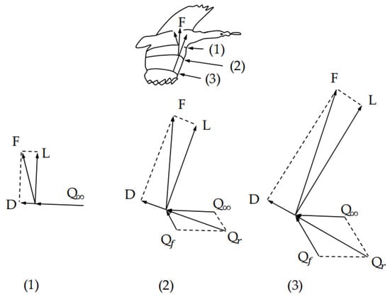
Figure 1.
Velocity-vector diagram at different wingspan locations for fast forward flight during downward flapping. Here, the lift and drag are defined based on the effective velocity combining forward and local flapping velocities. For the entire vehicle, the lift is defined to be normal to the forward velocity and the drag or thrust in the horizontal direction.
The first characteristic is the relatively low Reynolds number. For large, manned aircraft, the Reynolds number is relatively high, and the transition often occurs very quickly; the laminar flow section does not maintain too long a distance on the wing. When considering the flow characteristics, the full turbulence model of the wing surface is often utilized. For migratory bird-like flapping-wing aircraft or general migratory birds, by combining their size and flight speed, we find that their Reynolds numbers in the cruising state are generally on the order of 105 [2]. This is very low compared to the Reynolds number of more than 106 for ordinary manned aircraft, so the common practices for manned aircraft cannot be followed when calculating lift and drag. Because the boundary layer is relatively thick and the laminar flow section is relatively long, inviscid methods or methods that assume fully turbulent flows tend to have relatively large errors. As shown in Figure 2, laminar flow separation, transition, and turbulent reattachment are the main flow characteristics in the Reynolds range of 105 [2].
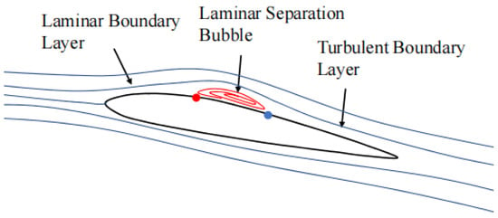
Figure 2.
Viscous flow characteristics of airfoil surface in the Reynolds range of 105.
The second characteristic is unsteadiness. The lift and thrust of the flapping-wing aircraft are provided by the moving wings, and the wings are always in an unsteady state. Due to the influence of unsteadiness, the aerodynamic force generated by the moving airfoil will be different from that of the steady state [3], so the steady method is not suitable for calculation. If the reduced frequency k is utilized to describe the unsteadiness of the wing, the reduction coefficient of large birds is below 0.2 [4].
1.2. Review of Literature
The research on flapping-wing airfoils has been carried out under low Reynolds numbers, and unsteady conditions have received comparatively little attention. Shyy Wei [4] studied the performances of different airfoils at low Reynolds numbers but did not study the lift and thrust characteristics of airfoils under unsteady conditions. Vest [5] applied an airfoil with thickness and camber instead of a flat airfoil in the flapping-wing aircraft model but did not consider the effect of viscosity. Carruthers [6] compared the performance of an eagle airfoil with the S1223 and the traditional Clack Y airfoil in a steady state, but research under unsteady conditions was not discussed. Lang [7] utilized the method of solving N–S equations to compare the performance of an owl airfoil with NACA0012 and NACA5506 under special laws of motion but did not consider the influence of transitions and applied a full turbulence model in the calculations. Wu [8] utilized the method of solving N–S equations to study the impact of the surging motion of the airfoil on performance, without considering the diverse requirements of the airfoils at different sections. Ashraf [9] studied the effect of varying airfoil thickness and camber on unsteady airfoils via numerical simulations for fully laminar and fully turbulent flow regimes, without considering laminar separation and transition. Chang [10] studied the aerodynamic characteristics of three-dimensional flapping wings, but the changes in demand for the airfoils at different sections of the wing were not considered, and the same airfoil was applied throughout the wingspan. DeLaurier [11] designed a flapping wing with an airfoil that changed continuously from wing tip to wing root, but the viscosity effect was not considered during the design, and the method for selecting airfoils was not provided.
Research on flapping-wing airfoils can be considered as an exploration of low-Reynolds-number unsteady airfoils. Anderson [12] conducted experiments to examine the propulsion efficiency of low-Reynolds-number airfoils. The study delved into the impact of pitch angle amplitude, Strouhal number (St), and phase angle on thrust and propulsion efficiency. He found that the thrust coefficient of the airfoil increases with the St number, but the propulsion efficiency shows an initial increase followed by a decrease as the St number increases. Young [13] employed a solver for the Navier–Stokes equations to investigate the propulsion efficiency of low-Reynolds-number airfoils, discovering that maximum efficiency is consistently achieved at Strouhal numbers ranging from 0.1 to 0.2. Tuncer [14] utilized the N–S equations solver to study the propulsion efficiency of the airfoil at low Reynolds numbers with plunge combined with pitch oscillation motion. The study revealed that efficiency reached its peak when the pitch and plunge phase difference was approximately 90°. Tuncer [15] studied the thrust and propulsion efficiency of a moving airfoil using the N–S equations solver. They found that a maximum propulsion efficiency and maximum thrust cannot be achieved at the same time, and the propulsion efficiency needs to be sacrificed to achieve maximum thrust.
The above experiments and simulations were carried out under the condition of a fully laminar flow or fully turbulent flow. For the problem in this article, the Reynolds number is in the range of 105, and the influence of the transition should be considered. Badrya [3] found that, when considering the transition model, the airfoil without thickness has an advantage over the airfoil with thickness in the Reynolds number range of 104, and the performance of airfoils with thicknesses in the Reynolds number range of 105 is superior. Windte [16] studied the propulsion efficiency of moving airfoils at low Reynolds numbers by solving the Reynolds-averaged N–S equations, in which the transition of the boundary layer was considered; it was found that the transition would greatly affect the propulsion efficiency. Radespiel [17] studied the laminar flow separation and rotation of unsteady airfoils with low Reynolds numbers by using PIV experiments and the N–S equations solver. The results show that separation and rotation have a considerable influence on the aerodynamics of unsteady airfoils.
1.3. Shortcomings with Existing Research
Existing studies on flapping-wing aircraft airfoils have some problems. Regarding computational models, a majority of the studies overlook the transition, opting for either a full turbulence model or a full laminar flow model. This choice introduces calculation errors in friction resistance and pressure resistance, failing to accurately reflect the characteristics within the Reynolds number range of 105 [2,3]. Regarding calculation methods, the commonly used computational fluid dynamics (CFD) method requires solving the Navier–Stokes equations at every point in space, ensuring high accuracy but consuming significant computing resources. For specific issues related to flapping-wing aircraft, such as unsteady problems and fluid–structure coupling problems, the time required for solutions is often impractical for application in the initial design process. Although the inviscid method is fast in calculation, it cannot calculate frictional resistance and it cannot capture low-Reynolds-number characteristics. Additionally, most studies on flapping-wing aircraft airfoils rely on empirical data and static aerodynamic force calculations, lacking a systematic investigation into different airfoils at various wing positions during motion [4,18]. Given the distinct performance requirements of airfoils at different wing sections, current research falls short in effectively explaining the principles and mechanisms governing the selection of flapping-wing airfoils.
1.4. The Innovations and Work of This Article
This article is the first attempt to apply the integral boundary layer equations combined with the panel method to study the aerodynamic performance of a flapping-wing airfoil. This article proposes a method that can quickly and accurately calculate the unsteady two-dimensional low-Reynolds-number aerodynamic forces. The calculation model adopted is the unsteady integral boundary layer method combined with the two-dimensional panel method and the transition model. The coupling problem of the boundary layer and inviscid flow is solved by the semi-inverse interaction method. This method can accurately and quickly calculate unsteady aerodynamic forces without neglecting the characteristics of the 105 range Reynolds number and is suitable for application in the early design stage.
This is the first time that the problem of airfoil selection at different sections of a flapping wing has been studied under unsteady conditions and considering transitions at low Reynolds numbers. The thrust coefficients, lift coefficients, propulsion efficiency, and moment coefficients of airfoils with different cambers at different sections of the wing during movement are calculated, respectively. The analysis includes the surface pressure coefficient, lift coefficient, thrust coefficient, and moment coefficient for a representative airfoil across different sections of the wing in a complete motion cycle. Results are then systematically analyzed and compared based on the distinct requirements for airfoils at various sections of the flapping wing. Ultimately, the study provides an explanation of the characteristics exhibited by different unsteady airfoils in distinct wing sections, accompanied by the formulation of principles guiding the selection of flapping airfoils.
2. Theoretical Method
According to Prandtl’s description of the boundary layer, the flow field can be divided into the boundary layer and the external flow field, enabling separate solutions and significantly enhancing calculation efficiency. The boundary layer equation is employed for solving the boundary layer problem, and the inviscid equation is utilized to calculate the external flow field. Eventually, the influence of the boundary layer on the external flow field is considered in a combined solution. This method has sufficient precision and is particularly suitable for the problem discussed in this paper, given the absence of airflow separation at the leading edges and the extensive trailing edge separations. In addressing the low-speed problem in this article, the incompressible flow assumption is made, allowing for appropriate simplification of the formulas.
2.1. Boundary Layer Calculation
Diverging from the comprehensive calculation of the global flow field, which necessitates the determination of parameters at every point within the boundary layer, the integral boundary layer method focuses solely on computing parameters along the airfoil surface. This approach significantly diminishes the number of unknowns, thereby reducing computational complexity. The simplicity of the integral boundary layer method renders it widely applicable in engineering [19,20,21], and it demonstrates adequate accuracy for various conventional problems.
2.1.1. Momentum and Kinetic Energy Equations
To simulate the laminar flow separation, the two-equation integration method is employed [22,23,24]. The integral form of the momentum equation and kinetic energy equation are obtained by integrating the differential form of the continuity equation and the momentum equation along the thickness of the boundary layer. In the case of unsteady conditions, the influence of the time t term should be added. The momentum and kinetic energy equations for the boundary layer can be ultimately reformulated as [20,25]
2.1.2. Laminar Integral Equations
To solve the laminar boundary layer, in addition to the momentum and kinetic energy equations, it is necessary to introduce the additional relationships of , , and . Drela [26] derives the following relationship, employing the Falkner–Skan profile family [27] for a given shape parameter, for the incompressible flow:
2.1.3. Turbulence Integral Equations
The turbulent boundary layer similarly encounters separation issues, where the separation zone expands gradually from the tail of the airfoil under an increase in angle of attack. To solve this problem, the two-equations model [28,29,30] is introduced, similar to the approach applied for laminar flow. In tackling the turbulent boundary layer, it is necessary to introduce the additional relationships of , , , and . For the coefficient of friction , Swafford’s [31] relation for the coefficient of friction under separated flow is applied here for incompressible flow:
Drela [26] applied Swafford’s velocity profile to establish the relationship for :
where is defined as
According to the concept of slip velocity introduced by Thomas [32], and considering the influence of the boundary wall surface layer and the outer layer, the equation of the dissipation coefficient is [26]
The dimensionless slip velocity is defined as
For in unsteady cases, following Green’s “lag-entrainment” equation [30], Ye [25] proposed a relatively simple formula considering unsteady effects:
is the equilibrium shear stress coefficient [25].
2.1.4. Transition
The transfer model is based on the linear stability theory [33,34]. The fundamental concept involves introducing small perturbations to a stable laminar flow and observing whether these perturbations diverge or dissipate over time. If the disturbance vanishes, the flow remains laminar. If the disturbance persists and increases to a threshold of approximately times the initial disturbance (typically N = 9, so about 8000 times), then the flow may undergo a transition to turbulence.
Provided the overall amplification factor N of the flow is greater than 9, it is considered that the transition occurs. Under different frequency disturbances and different pressure gradients, the growth curve of the disturbance based on the Falkner–Skan velocity profile family can be calculated by the Orr–Sommerfeld equation [35], and the envelope of these growth curves can be regarded as a straight line [36]. N can be calculated as [26]
is the Reynolds number of the boundary layer momentum thickness when the disturbance begins to appear.
2.2. 2-D Unsteady Panel Method
2.2.1. Panel Method Model
This paper adopts the steady method similar to Hess (HSPM) [37] and improves it, to make it suitable for computing unsteady situations, as shown in Figure 3.
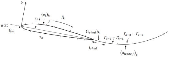
Figure 3.
Airfoil panels and wake panels of 2-D unsteady panel method.
The airfoil geometry is represented by short, straight line elements called panels. There are two types of elements in this method: the source panel and the vorticity panel. The strength of the source is constant, and the value of each unit is different; the strength of the vorticity is also constant but uniform across all vorticity panels on the airfoil. For unsteady flows, the element strength varies with time, so the time step is introduced. The line source strength and the line vorticity strength need to be solved at each time step. According to the Helmholtz theorem, the total circulation in the flow field is conserved, so the change of the circulation on the airfoil surface must cause a change of equal magnitude and opposite sign in the wake. In unsteady conditions, the wake vorticity panel will shed from the trailing edge. According to Helmholtz’s theorem,
where is the length of the shed vorticity panel, and is the strength of the shed vorticity panel. As time progresses, the wake vorticity panel is continuously shed, and a vorticity line with varying strength is generated behind the airfoil. The strength of the first wake panel needs to be calculated with the airfoil vorticity. Starting from the second wake panel, the calculation is carried out according to the total vorticity of the wake, with the vorticity panels remaining unchanged. In the unsteady viscous case, both the wake vorticity panels and the wake source panels should be included to simulate the boundary layer thickness effect. It is assumed that the viscous wake flows smoothly along the trailing edge of the airfoil with zero thickness.
2.2.2. Wake Shape
The source panels and vorticity panels on the airfoil surface will affect the wake, and the wake vorticity panels will also affect themselves. The wake vorticity panels do not bear forces in the airflow, and each wake node moves with the airflow. This complexity arises when dealing with unsteady and viscous cases, in contrast to steady and inviscid scenarios. Generally, knowing the position of the wake node at time k − 1 and velocity , allows for determination of the position of the wake vortex line node at time k. The position of the wake source panels is the same as that of the wake vorticity panels.
2.2.3. Boundary Layer Thickness Effect
In the case of a low Reynolds number, the boundary layer is thick relative to the airfoil. The displacement effect caused by the influence of the viscous boundary layer will affect the inviscid flow field, so the influence of the boundary layer on the overall flow field should be considered in the calculation. The presence of the boundary layer results in a loss of mass flow compared to the inviscid flow field. In order to maintain the mass continuity in the inviscid flow field, it is necessary to move the boundary outward by the displacement thickness of the boundary layer to solve the problem. To simulate displacement effects, a series of additional source panels of strength are added to the airfoil surface, which generate a virtual wall mass flow (s is the line coordinate). The required additional line source strength is
2.3. Equation Creation
The Neumann boundary condition is used here, which assumes that the velocity does not penetrate the airfoil surface and the normal velocity at the airfoil surface and viscous wake control points is zero. According to the unsteady Kutta condition [38] at the trailing edge,
where and are the tangential velocity of the trailing edge of the airfoil at time k, and and are the velocity potentials at the trailing edge at time k.
2.4. Viscous/Inviscid Interaction
The method in this paper divides the entire flow field into two parts: the inviscid flow field region outside the boundary layer and the thin viscous shear layer region. In order to solve the entire flow field, an appropriate coupling method is required. In order to solve the Goldstein singularity problem [39] in the coupling problem, this paper adopts the semi-inverse coupling method [40,41]. This coupled method solves the velocity on the outer surface of the boundary layer in both the forward solution process and the reverse solution process, as shown in Figure 4. In the forward solution process, using and Equation (14), the influence of the boundary layer thickness effect on the surface flow field can be obtained. The forward velocity can be calculated using linear equations combined with the known panel strength and additional line source strength. In the reverse solution process, by combining the relationship between and () and the boundary layer equations, Newton’s method [26] can be utilized to solve the nonlinear equations to obtain the reverse velocity . To ensure the convergence of the calculation, the Crank–Nicolson [42] method is utilized to discretize the boundary layer Equations (1), (2) and (11). In the low-velocity boundary layer flow, the boundary layer flow tends to maintain mass flow conservation: constant. According to this concept, after the n-th iteration in the iterative calculation, the new displacement thickness is
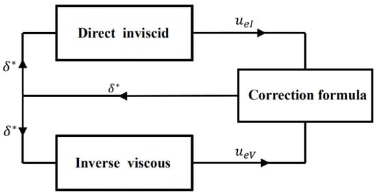
Figure 4.
Calculation process of semi-inverse coupling method.
In the iteration, the relaxation factor RF can be used to improve the convergence speed and reduce calculation time:
The calculation is iterated until the error between and is less than the error limit.
2.5. Performance Parameter
In unsteady flows, according to the unsteady Bernoulli theorem [38],
where is the motion velocity on the airfoil relative to the fixed coordinate system, Q is the airflow velocity on the airfoil, and is the velocity potential. The airfoil makes a pitch motion around the 1/4 chord line and is coupled with plunge motion. The moving airfoil generates a time-varying horizontal thrust , vertical lift , and airfoil torque . , , and are the time-averaged thrust, lift, and torque within a cycle:
is the average power of a cycle; it incorporates the work done by the plunge motion and pitch motion:
For convenience of discussion and research, dimensioned quantities can be transformed into dimensionless coefficients:
Propulsion efficiency is defined as the ratio of the thrust coefficient to the power coefficient:
3. Method Validation
In order to verify the validity of the calculation method, the analysis and verification of the steady state and the unsteady state are carried out, respectively.
3.1. Steady State Situation
As shown in Figure 5a, the airfoil surface pressure coefficient of the NACA4415 airfoil at a Reynolds number of 235,000 and an angle of attack of 4° is compared with the experimental and Xfoil [19] calculation results. The experimental data come from LeBlanc [43]. As shown in Table 1, as the airfoil panel numbers increase, the relative errors of the force coefficients decrease, which demonstrates convergence. Considering the calculation accuracy and time cost, the number of airfoil panels is selected to be 144 for all subsequent simulations in this paper. It can be seen that this method is in good agreement with the experimental results. It shows that the laminar flow separation occurs on the upper surface under the adverse pressure gradient, and the position of the transition and reattachment are predicted. For the area of laminar flow separation, the change of pressure coefficient is small, forming a shape similar to a step, and the pressure coefficient drops rapidly after transition. The reverse pressure gradient on the lower surface is very small, to maintain laminar flow without separation and transition.
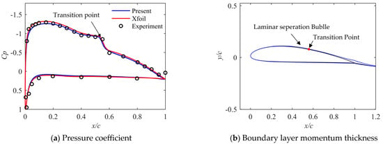
Figure 5.
Comparison of present method’s pressure coefficient and boundary layer momentum thickness against Xfoil results and experimental results.

Table 1.
The influence of the panel numbers on calculation results.
As shown in Figure 5b, after laminar flow separation, the momentum thickness of the boundary layer increases significantly in the area where the separation bubble exists. After the transition occurs, the momentum thickness suddenly decreases when the flow becomes turbulent and gradually increases until the trailing edge.
In addition to the airfoil surface pressure coefficient, it is also necessary to compare the boundary layer parameters for the method and experiment. For the NACA4415 airfoil, when the Reynolds number is 235,000 and the angle of attack is 4°, the upper airfoil boundary layer shape parameter H and momentum thickness are compared with the Xfoil and experiments, as shown in Figure 6. It can be seen that there is a sudden change in the shape parameter H and momentum thickness near the transition point, and the result is in good agreement with the experiment.
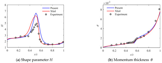
Figure 6.
Comparison of present method’s boundary layer shape parameter H and momentum thickness against Xfoil results and experimental results.
In practice, we are more interested in the lift and drag coefficients of the airfoil at low Reynolds numbers. As shown in Figure 7, for the NACA4415 airfoil at a Reynolds number of 334,000, the calculation results of the lift coefficient , drag coefficient , and moment coefficient are compared with the Xfoil, Fluent v18.1 software and experimental results. Fluent is a general commercial software based on the N–S equations. The settings in Fluent are as follows: the turbulence model is the k– model, the turbulence model is the model; the velocity–pressure coupling algorithm is SIMPLEC; and the space-specific dissipation rate is discretized with a second-order upwind scheme. The number of the cells is 69,940. Experimental data are from Jacobs [44].

Figure 7.
Comparison of present method’s , , and values against Xfoil, Fluent results, and experimental results at a Reynolds number of 334,000.
It can be seen that the lift–drag characteristics match well when the angle of attack is not too large. As the angle of attack increases, the calculation error of the lift–drag ratio gradually increases. This may be because the separation of the trailing edge becomes more serious as the angle of attack increases.
3.2. Unsteady State Situation
For the unsteady viscous case, the calculation results of Fluent and the experimental results of Carta [45] are compared with the calculation results. The setup in Fluent is generally the same as the static case, and the overset mesh is applied to calculate the dynamic characteristics. The experiment used the SC1095 airfoil, the experimental Reynolds number is 315,000, the airfoil makes periodic pitching motions around the 1/4 axis, the reduction coefficient of pitching motion is k = 0.25, and the law of pitching motion is . The experimental values and calculation comparisons of the unsteady vertical force coefficient on the airfoil are shown in Figure 8a.
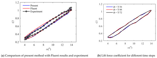
Figure 8.
Unsteady lift coefficient.
It can be seen that the calculations are in good agreement with the Fluent calculations and experiments. The settings of the present method in the article and Fluent are the same as the static situation, and the overlapping grids method in Fluent is utilized to calculate the unsteady aerodynamic force. In Fluent, the calculations are performed with 200 time steps per cycle, utilizing a total around cells, which is deemed sufficient for comparison purposes [46]. The lift force coefficients at different time steps are presented in Figure 8b. Small discrepancies can be seen in the force coefficients between the three time steps. Considering the calculation accuracy and time cost, 48 steps per period is selected for all subsequent simulations in this article. The numerical calculations are performed on a Lenovo Intel(R) Core(TM) i7-4710MQ CPU @ 2.50 GHz. It takes about 100 min for Fluent to calculate one cycle of airfoil motion, and the method in this article takes less than 5 min.
4. Results and Discussion
4.1. Wing Model
The flapping-wing aircraft’s original configuration was modeled after the Canada Goose. As shown in Figure 9, assuming that the half-wing-span of the flapping wing is 0.8 m, the aspect ratio of the wing is 6, and the root-to-tip ratio is 2 with a wing root chord length of 0.3 m. With a flight velocity during migration of 15 m/s, the corresponding Reynolds number ranges from 187,500 to 375,000. The reduced frequency k of large migratory birds is below 0.2 [1]. Initially, the reduced frequency k is set to be around 0.15, the average aerodynamic chord length is used in the calculation of the reduced frequency, and the flapping period is set to 0.314 s.
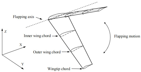
Figure 9.
The positions of the three characteristic chords on the wing.
The operational conditions of the airfoil profiles vary at each span of the flapping wing, necessitating distinct requirements for each airfoil. As shown in Figure 9, three characteristic chords are identified: the wing tip chord, the chord at 0.67 times the span, and the chord at 0.33 times the span of the wing. The suitability of each airfoil for its corresponding location on the wing needs to be investigated.
Different airfoils are analyzed under the relatively simple sinusoidal motion law. The airfoils studied are the symmetrical NACA0012, NACA2412 with 2% camber, NACA5412 with 5% camber, and GOE225 with 7% camber, as shown in Figure 10. We discuss the influence of different motion parameters on the thrust coefficient, lift coefficient, moment coefficient, and propulsion efficiency at different average angles of attack as a function of the pitch amplitude. The law of airfoil motion is
where represents the geometric angle of attack of the airfoil, is the pitch amplitude of the airfoil, and is the average angle of attack of the airfoil motion. Additionally, is the displacement of the plunge motion, is the plunge amplitude, T is the period time of the motion, and is the phase difference between the pitch motion and plunge motion. The schematic diagram of the combination of airfoil pitch and plunge motions at different moments is shown in Figure 11a. As shown in Figure 11b, due to the movement of the airfoil, the resultant aerodynamic force will have a thrust component. The effective angle of attack of the airfoil is influenced by the combined effect of plunge and pitch motions and the induced velocity of the wake.

Figure 10.
Geometry of the four airfoils studied in the article.
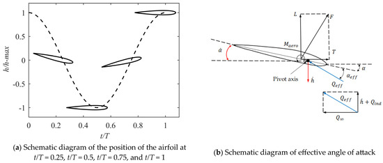
Figure 11.
Airfoil motion and effective angle of attack.
4.2. Wingtip Airfoil
The thrust of the entire aircraft is predominantly generated by the outer wing. The forward flight velocity is 15 m/s, the cycle time is T = 0.314 s, and the reduced frequency is k = 0.1. Assuming the wing-flapping dihedral angle is 30° and the plunge amplitude is = 2.75, the Strouhal number is St = 0.143. According to Anderson [12], a pitch phase lag improves thrust and propulsion efficiency, so we let . The Reynolds number of the wingtip is Re = 187,500. As shown in Table 2, different airfoils with different average angles on the wingtip are studied.

Table 2.
Different airfoils with different average angles on wingtip chord.
The variations in thrust, lift, moment coefficient, and propulsion efficiency under changes in pitching amplitude are shown in Figure 12. It can be seen that the thrust coefficient increases as the pitch amplitude decreases. The lift coefficient, influenced by the camber of the airfoil and the average angle of attack, can be roughly categorized into four levels. The moment coefficient appears to be primarily related to the camber of the airfoil, exhibiting a rapid increase with higher camber values. The propulsion efficiency initially increases and then decreases with the pitch amplitude.
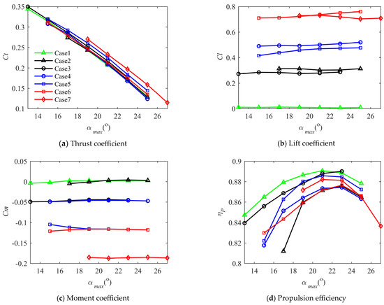
Figure 12.
Comparison of , , , and for different motion laws of different airfoils on wingtip chord.
It can be seen from Case 1 that the thrust coefficient is large when the airfoil pitch amplitude is small. The pitch amplitude does not decrease to zero because the calculation stops when the trailing edge of the airfoil has a relatively large separation (about 1/4 of the chord length). The effective angle of attack of the airfoil is influenced by the combined effect of plunge and pitch motions and the induced speed of the wake. With a small airfoil pitch amplitude, the effective angle of attack of the airfoil is relatively large, resulting in a large thrust coefficient. The propulsion efficiency has a maximum value, decreasing if the pitch amplitude is excessively large or small. When the pitch amplitude is overly small, a substantial effective angle of attack is generated in the airfoil motion, leading to airflow separation and a reduction in the lift-to-drag ratio. When the pitch amplitude is excessively large, the effective angle of attack of the airfoil is small, resulting in a very low lift-to-drag ratio.
Comparing Case 1 with Case 2 and Case 3, it can be seen that when lift generation is not considered, the thrust coefficient and propulsion efficiency of the NACA0012 airfoil are highest. Considering the generation of lift, the airfoil with small camber NACA2412 has advantages in terms of thrust and propulsion efficiency compared with NACA0012. The moment coefficient changes slightly with the maximum pitch amplitude. The NACA0012 airfoil is symmetrical, so the moment coefficient is almost zero, and the NACA2412 moment coefficient is well controlled, with only a small moment coefficient. Comparing Case 4 with Case 3, the lift coefficient is larger but the thrust coefficient and propulsion efficiency are smaller. In the comparison between Case 4 and Case 5, under similar lift coefficients, the NACA5412 airfoil demonstrates a better thrust coefficient and propulsion efficiency, but the moment coefficient is greater than that of the NACA2412 airfoil. Excessive moment coefficients can increase the trim drag of the entire aircraft, offsetting some of the benefits in lift and propulsion efficiency. Under the same stability margin, the airfoil with a large moment has a large trim drag. Case 6 and Case 7 are comparisons of the medium-camber airfoil NACA5412 and the large-camber airfoil GOE225 for similar lift coefficients. It can be seen that the thrust coefficient and propulsion efficiency are dominated by GOE225, but the moment coefficient of the large-camber airfoil is obviously large, and the maximum thrust coefficient is small.
In a comprehensive assessment, the airfoil with a smaller camber exhibits a stronger ability to generate thrust and has a higher propulsion efficiency. For the same airfoil, as the lift coefficient increases, the thrust coefficient and propulsion efficiency decrease. When the thrust coefficient and the lift coefficient are required simultaneously, increasing the camber of the airfoil is more effective than increasing the angle of attack of the airfoil. Deviating too much from the average angle of attack of zero degrees results in poor propulsion efficiency. A higher camber is relatively unsuitable for generating thrust, as cambered airfoils are designed for positive angles of attack, and the lift-to-drag ratio performs poorly at negative angles of attack. A larger cambered airfoil means a higher moment coefficient. For the flapping-wing aircraft, a small camber airfoil should be selected at the wing tip.
To investigate the performance of the airfoil surface, the pressure distribution on the wingtip NACA2412 airfoil surface, along with the lift coefficient, thrust coefficient and moment coefficient during one cycle, are presented. The motion parameters are taken from Case 2, and the pitch amplitude .
As shown in Figure 13, when t/T = 0.5 and t/T = 1, it can be seen that the effective angle of attack is within the range of small angles of attack, and the phenomena of laminar separation and transition occur on the upper and lower surfaces of the airfoil. At t/T = 0.25, the airfoil is in a high angle of attack, and laminar flow separation and transition occur in a short distance on the upper surface of the airfoil. There is obviously a section of the trailing edge where the pressure coefficient remains unchanged, indicating trailing edge airflow separation. The lower airfoil maintains laminar flow without transition. At t/T = 0.75, it is in a state of a large negative angle of attack, and it can be seen that the airflow velocity on the lower surface of the airfoil increases rapidly at a large negative angle of attack. The effective angle of attack of the wingtip airfoil undergoes significant changes during motion, enabling the generation of a large thrust coefficient in both the downward and upward phases.

Figure 13.
The pressure coefficient of the upper and lower surface of the NACA2412 airfoil from Case 2 with on the wingtip at different times during the period.
As shown in Figure 14, the lift coefficient during a cycle is generally a sinusoidal pattern. It is predominantly positive during the downstroke and predominantly negative during the upstroke. The positive lift coefficient is numerically greater than the negative lift coefficient, so the lift coefficient within the entire cycle is positive. The thrust coefficient is positive in both the upstroke and downstroke motions, with a notably greater thrust coefficient during the downstroke than in the upstroke. The moment coefficient varies with the angle of attack, and it seems that the moment coefficient will be larger when the angle of attack is small.

Figure 14.
,, and of NACA2412 airfoil from Case 2 with on wingtip during the period.
4.3. Outer-Wing Airfoil
The current focus is on studying the airfoil performance at the outer section of the wing at 0.67 times the wingspan. The outer part of the wing needs to generate both thrust and lift, which meets more requirements than the wingtip. Based on the previous discussion, it is suggested to select a cambered airfoil for this purpose. The motion of the outer-wing section is determined by the wingtip, assuming the entire wing adopts a linear twist. Following the motion laws of wingtips, the period is T = 0.314 s; thus, the reduced frequency is k = 0.133. The plunge amplitude of the airfoil at 0.67 span is = 1.33, and the Strouhal number is St = 0.113. The phase difference is . The Reynolds number is 250,000. As shown in Table 3, different airfoils with different average angles on the outer wing chord were examined.

Table 3.
Different airfoils with different average angles on outer wing chord.
As shown in Figure 15, the variation laws of parameters such as the thrust coefficient of the airfoil are generally the same as those obtained at the wingtip airfoil. However, due to the reduced plunge amplitude, the thrust coefficient and propulsion efficiency are much smaller compared to the wingtip cases. The lift coefficients are categorized into three levels, to analyze the performance under different lift coefficients.
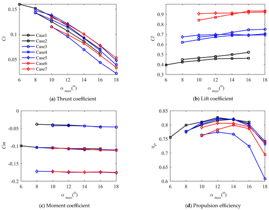
Figure 15.
Comparison of , , , and for different motion laws of different airfoils on outer wing chord.
Through the comparison of Case 1 and Case 2, it can be seen that when the average lift is close, the NACA5412 airfoil exhibits advantages in thrust coefficient and propulsion efficiency. However, this comes at the cost of an increased moment coefficient compared to the NACA2412 airfoil. Comparing Case 3, Case 4, and Case 5, we see that when the average lift coefficient is moderate, the small-camber NACA2412 airfoil experiences a significant decrease in propulsion efficiency and thrust coefficient due to excessive deviation from the average zero angle of attack. The performance of the large-camber GOE225 airfoil is similar to the medium-camber NACA5412 airfoil in thrust coefficient and lift coefficient, but the moment coefficient is noticeably increased. The medium-camber NACA5412 airfoil performs well in terms of thrust coefficient and propulsion efficiency, with a moderately increased moment coefficient. From Case 6 and Case 7, it can be seen that although the lift coefficient increases under a higher average angle of attack, the thrust coefficient and propulsion efficiency decrease substantially, necessitating a trade-off in actual use.
In a comprehensive assessment, the airfoils at the outer-wing section must take into account thrust and lift requirements simultaneously. At the same time, avoiding an excessively large moment coefficient, which increases trim drag, is essential. It is appropriate to select a medium-camber airfoil at the outer wing, and to ensure that the average angle of attack of the airfoil remains small during use.
Similarly, the airfoil pressure distribution of the NACA5412 airfoil at 0.67 of the wingspan, as well as the lift coefficient, thrust coefficient, and moment coefficient during the period, are studied. The motion parameters are taken from Case 4, and the pitch amplitude .
As shown in Figure 16, when t/T = 0.5 and t/T = 1, the airfoil is in a state of a small angle of attack, and laminar flow separation and transition have occurred on the upper and lower surfaces. At this time, the lift force of the airfoil is small and the lift-to-drag ratio is poor. At t/T = 0.25, the airfoil is in a high angle of attack. Compared with the small-camber airfoil, the airflow velocity on the upper airfoil surface is not very fast. It can also be seen that airflow separation has occurred at the trailing edge. At t/T = 0.75, the airfoil is in a large negative angle of attack. The velocity of the lower airfoil surface increases rapidly at the leading edge to form a sharp suction peak, and laminar flow separation and transition occur on the upper airfoil surface near the trailing edge. This indicates that the cambered airfoil is not suitable for operating under negative angles of attack. Compared with the wing tip, the effective angle of attack range of the outer wing is not very large, and the thrust generated is smaller. However, due to the larger camber and average angle of attack of the airfoil, the overall lift coefficient is also larger.

Figure 16.
The pressure coefficient of the upper and lower surface of the NACA5412 airfoil from Case 4 with on the outer-wing chord at different times during the period.
As shown in Figure 17, throughout the entire cycle, the airfoil lift coefficient is larger than that of the wingtip airfoil. The negative lift coefficient during the upstroke is smaller, but it still produces negative lift coefficients during the upstroke. The thrust coefficient of the airfoil is smaller than that of the wingtip airfoil in the whole cycle, and almost no thrust is generated during the upstroke. The law of the moment coefficient is roughly the same as that of the airfoil at the wingtip, but the absolute value is larger due to the difference of the airfoil.

Figure 17.
, and of NACA5412 airfoil from Case 4 on outer-wing chord during the period.
4.4. Inner-Wing Airfoil
Finally, the airfoil performance at the inner section of the wing, located at 0.33 times the wingspan, is examined. The inner wing primarily generates lift, so a small-camber airfoil is not considered. The period is still T = 0.314 s, and the reduced frequency is k = 0.167. The plunge amplitude of the airfoil at 0.33 span is = 0.53, and the Strouhal number is St = 0.0565. The phase difference is . The Reynolds number is 325,000. As shown in Table 4, different airfoils with different average angles on the inner wing chord are under examination.

Table 4.
Different airfoils with different average angles on inner wing chord.
According to Figure 18, due to the small Strouhal number, the thrust coefficient of the inner-wing section is very small, and the propulsion efficiency is very low. When the maximum pitch amplitude is relatively large, the airfoil even creates drag over the entire motion cycle. In this case, the propulsion efficiency is assumed to be zero. Therefore, the inner wing should focus on generating lift, leaving the task of generating thrust to the outer section of the wing.
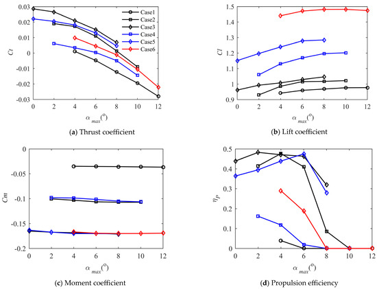
Figure 18.
Comparison of , , , and for different motion laws of different airfoils on inner wing chord.
According to Case 1, Case 2, and Case 3, the lift coefficient and thrust coefficient of the small-camber airfoil are relatively poor, suggesting that it is entirely unsuitable as an airfoil for the inner wing. When the lift coefficient is not particularly large, the thrust coefficient and lift coefficient of the airfoil with medium camber are not as good as those of the airfoil with a large camber. According to Case 4 and Case 5, the medium-camber airfoil does not perform well when a large lift coefficient is required. The performance of the large-camber airfoil is significantly better than that of the medium-camber airfoil after paying the price of a larger moment coefficient. According to Case 6, the large-camber airfoil has the potential to increase the lift coefficient. From the perspective of lift-to-drag ratio, it is not recommended that the inner-wing airfoil have a large range of effective angles of attack. It is best for the airfoil to work within the range of the angle of attack where the lift-to-drag ratio is largest. The large camber airfoil has inherent advantages for situations where lift is mainly required.
The pressure distribution of the GOE225 airfoil at 0.33 times the span of the wing, as well as the lift coefficient, thrust coefficient, and moment coefficient during one cycle, are studied. The motion parameters are taken from Case 5, and the pitch amplitude .
From Figure 19, it can be seen that when t/T = 0.5 and t/T = 1, the airfoil operates at an effective medium angle of attack. The upper airfoil surface has a laminar separation and transition, and the airfoil is near the angle of attack of the maximum lift–drag ratio. At t/T = 0.25, the airfoil adopts a large angle of attack, and the pressure coefficient on the upper surface, near the trailing edge, remains unchanged, signifying the occurrence of airflow separation. At t/T = 0.75, the airfoil is at a small angle of attack, and there is laminar flow separation and transition on both the upper and lower surfaces. From the pressure coefficient curve, the airfoil effective angle of attack is always near the best lift–drag ratio angle of attack, which is beneficial for generating lift.

Figure 19.
The pressure coefficient of the upper and lower surfaces of the GOE225 airfoil from Case 5 with on the outer-wing chord at different times during the period.
As shown in Figure 20, the lift coefficient remains positive throughout the entire cycle and is much larger than that of the airfoil in the outer section of the wing. While the airfoil exhibits a positive lift coefficient during the upstroke, it is notably smaller than during the downstroke. Due to the weak unsteadiness, the thrust coefficient remains small throughout the cycle. The moment coefficient exhibits minimal variation in the whole cycle and is significantly larger than that of the airfoil with a medium camber at the outer wing.

Figure 20.
, , and of GOE225 airfoil from Case 5 with on the outer-wing chord during the period.
5. Conclusions
In order to select a suitable airfoil in the early stages of flapping-wing design, a relatively simple method is developed to calculate the unsteady two-dimensional airfoil aerodynamic forces with a Reynolds number in the range of . The method adopts the integral laminar and turbulent boundary layer model of the two-equation method, the transition model, and the unsteady two-dimensional panel method. To couple these models, the semi-inverse interaction method is utilized. Under this method, the thrust coefficient, lift coefficient, propulsion efficiency, and moment coefficient of different airfoils under different motion laws are respectively studied. The study delves into flow characteristics across different wing sections, analyzing the performance of distinct airfoils under unsteady conditions; the selection principles of flapping airfoils are given. The conclusions of this article are as follows:
- The method proposed in this article can quickly and accurately calculate the steady and unsteady aerodynamic forces of the airfoil in a Reynolds number range of 105. This method can exhibit typical low-Reynolds-number phenomena, such as laminar flow separation, transition, and turbulent separation at the trailing edge. Compared with the inviscid model, it can more accurately calculate the viscous aerodynamic force. Compared with the method of solving the global N–S equations, it saves a lot of time and is suitable for the early design stage.
- The lift coefficient of the unsteady airfoil increases with the increase of the airfoil camber and average angle of attack, and the thrust coefficient decreases with the increase of the airfoil camber and average angle of attack. The propulsive efficiency of the same airfoil increases and then decreases with pitch amplitude, and airfoils with a small curvature and big plunge amplitude have a high propulsive efficiency. The moment coefficient only increases with the airfoil camber.
- The airfoil’s camber significantly impacts the lift coefficient, thrust coefficient, and propulsion efficiency. To optimize flight efficiency, it is essential to choose airfoils with varying cambers for different sections of the ornithopter’s wings, aligning with the distinct requirements of each wing section.
The outer section of the wing is the main source of thrust for the flapping wing. It is more suitable to adopt a small-camber airfoil at the wingtip, so that a larger thrust coefficient and propulsion efficiency can be obtained with a smaller moment coefficient. For simultaneous requirements of thrust and lift while preserving a high propulsion efficiency, employing a medium-cambered airfoil on the outer wing section proves advantageous. This choice allows for the attainment of a favorable thrust coefficient, propulsion efficiency, and lift coefficient, without incurring an excessive moment coefficient. The inner wing is the main part of the wing to generate lift, and the large-camber airfoil can generate a large lift coefficient with a high lift-to-drag ratio, which has inherent advantages.
The airfoils of different wing sections need to operate under the appropriate average angles of attack and pitch amplitudes, which requires further discussion of the 3-dimensional wing.
Author Contributions
Conceptualization, M.Q., W.Z. and S.L.; methodology, M.Q. and W.Z.; software, M.Q.; validation, M.Q. and W.Z.; formal analysis, M.Q.; investigation, M.Q. and W.Z.; resources, S.L.; data curation, M.Q.; writing—original draft preparation, M.Q.; writing—review and editing, M.Q., W.Z. and S.L.; visualization, M.Q.; supervision, S.L.; project administration, S.L.; funding acquisition, S.L. All authors have read and agreed to the published version of the manuscript.
Funding
This research received no external funding.
Institutional Review Board Statement
Not applicable.
Informed Consent Statement
Not applicable.
Data Availability Statement
The data can be obtained upon request from the corresponding author.
Conflicts of Interest
The authors declare no conflicts of interest. Author Wenguo Zhu was employed by the company Norinco Group Institute of Navigation and Control Technology. The remaining authors declare that the research was conducted in the absence of any commercial or financial relationships that could be construed as a potential conflict of interest.
Nomenclature
| dissipation coefficient | |
| skin friction coefficient | |
| shear stress coefficient | |
| shape parameter | |
| kinetic energy shape parameter | |
| momentum thickness Reynolds number | |
| boundary layer edge velocity | |
| boundary layer thickness | |
| displacement thickness | |
| thin shear layer coordinates | |
| momentum thickness | |
| kinetic energy thickness | |
| boundary layer edge viscosity | |
| density | |
| boundary layer density | |
| reduced frequency | |
| Strouhal number |
References
- Shyy, W.; Aono, H.; Kang, C. An Introduction to Flapping Wing Aerodynamics; Cambridge University Press: Cambridge, UK, 2013. [Google Scholar]
- Winslow, J.; Otsuka, H.; Govindarajan, B.; Chopra, I. Basic understanding of airfoil characteristics at low Reynolds numbers (104–105). J. Aircr. 2018, 55, 1050–1061. [Google Scholar] [CrossRef]
- Badrya, C.; Govindarajan, B.; Chopra, I. Basic understanding of unsteady airfoil aerodynamics at low Reynolds numbers. In Proceedings of the AIAA Aerospace Sciences Meeting, Kissimmee, FL, USA, 8–12 January 2018. [Google Scholar]
- Shyy, W.; Klevebring, F.; Nilsson, M. Rigid and flexible low Reynolds number airfoils. J. Aircr. 1999, 36, 523–529. [Google Scholar] [CrossRef]
- Vest, M.S. Unsteady Aerodynamics and Propulsive Characteristics of Flapping Wings with Applications to Avian Flight. Ph.D. Thesis, University of California, San Diego, CA, USA, 1996. [Google Scholar]
- Carruthers, A.C.; Walker, S.M.; Thomas, A.L.R. Aerodynamics of aerofoil sections measured on a free-flying bird. Proc. Inst. Mech. Eng. Part G J. Aerosp. Eng. 2009, 224, 855–864. [Google Scholar] [CrossRef]
- Lang, X.Y.; Song, B.F.; Yang, W.Q. Aerodynamic performance of owl-like airfoil undergoing bio-inspired flapping kinematics. Chin. J. Aeronaut. 2021, 34, 239–252. [Google Scholar] [CrossRef]
- Wu, T.; Song, B.F.; Song, W.P.; Yang, W.Q.; Xue, D.; Han, Z.H. Lift performance enhancement for flapping airfoils by considering surging motion. Chin. J. Aeronaut. 2022, 35, 194–207. [Google Scholar] [CrossRef]
- Ashraf, M.A.; Young, J.; Lai, J.C. Reynolds number, thickness and camber effects on flapping airfoil propulsion. J. Fluids Struct. 2011, 27, 145–160. [Google Scholar] [CrossRef]
- Chang, X.; Zhang, L.; Ma, R.; Wang, N. Numerical investigation on aerodynamic performance of a bionic flapping wing. Appl. Math. Mech. 2019, 40, 1625–1646. [Google Scholar] [CrossRef]
- DeLaurier, J.D. The development of an efficient ornithopter wing. Aeronaut. J. 1993, 97, 153–162. [Google Scholar] [CrossRef]
- Anderson, J.M.; Streitlien, K.; Barrett, D.S. Oscillating foils of high propulsive efficiency. J. Fluid Mech. 1998, 360, 41–72. [Google Scholar] [CrossRef]
- Young, J.; Lai, J.C. Oscillation frequency and amplitude effects on the wake of a plunging airfoil. AIAA J. 2004, 42, 2042–2052. [Google Scholar] [CrossRef]
- Tuncer, I.H.; Walz, R.; Platzer, M.F. A computational study on the dynamic stall of a flapping airfoil. In Proceedings of the 16th AIAA Applied Aerodynamics Conference, Albuquerque, NM, USA, 15–18 June 1998. [Google Scholar]
- Tuncer, I.H.; Kaya, M. Optimization of flapping airfoils for maximum thrust and propulsion efficiency. AIAA J. 2005, 43, 2329–2341. [Google Scholar] [CrossRef]
- Windte, J.; Radespiel, R. Propulsive efficiency of a moving airfoil at transitional low Reynolds numbers. AIAA J. 2008, 46, 2165–2177. [Google Scholar] [CrossRef]
- Radespiel, R.; Windte, J.; Scholz, U. Numerical and experimental flow analysis of moving airfoils with laminar separation bubbles. AIAA J. 2007, 45, 1346–1356. [Google Scholar] [CrossRef]
- Larijani, R.F. A Non-Linear Aeroelastic Model for the Study of Flapping-Wing Flight. Ph.D. Thesis, University of Toronto, Toronto, ON, Canada, 2001. [Google Scholar]
- Drela, M. XFOIL: An analysis and design system for low Reynolds number airfoils. In Low Reynolds Number Aerodynamics: Proceedings of the Conference Notre Dame, Indiana, USA, 5–7 June 1989; Springer: Berlin/Heidelberg, Germany, 1989. [Google Scholar]
- Ozdemir, H.; van Garrel, A.; Koodly Ravishankara, A. Unsteady interacting boundary layer method. In Proceedings of the 35th Wind Energy Symposium, Grapevine, TX, USA, 9–13 January 2017. [Google Scholar]
- García, N.R. Unsteady Viscous-Inviscid Interaction Technique for Wind Turbine Airfoils. Ph.D. Thesis, Technical University of Denmark, Lyngby, Denmark, 2011. [Google Scholar]
- Crimi, P.; Reeves, B.L. Analysis of leading edge separation bubbles on airfoils. AIAA J. 1976, 14, 1548–1555. [Google Scholar] [CrossRef]
- Horton, H.P. A Semi-Empirical Theory for the Growth and Bursting of Laminar Separation Bubbles; Technical Report No. 1073; Her Majesty’s Stationery Office: London, UK, 1949. [Google Scholar]
- Eppler, R.A.; Somers, D.M. A Computer Program for the Design and Analysis of Low-Speed Airfoils; Technical Report No. 80210; NASA: Washington, DC, USA, 1980.
- Ye, B. The Modeling of Laminar-to-Turbulent Transition for Unsteady Integral Boundary Layer Equations with High Order Discontinuous Galerkin Method. Master’s Thesis, Delft University of Technology, Delft, The Netherlands, 2015. [Google Scholar]
- Drela, M.; Giles, M.B. Viscous-inviscid analysis of transonic and low Reynolds number airfoils. AIAA J. 1987, 25, 1347–1355. [Google Scholar] [CrossRef]
- Schlichting, H.; Kestin, J. Boundary Layer Theory; McGraw-Hill: New York, NY, USA, 1961; pp. 195–207. [Google Scholar]
- Eppler, R. Practical Calculation of Laminar and Turbulent Bled-Off Boundary Layers; Technical Report No. NASA-TM-75328; NASA: Washington, DC, USA, 1978.
- Head, M.R.; Patel, V.C. Improved Entrainment Method for Calculating Turbulent Boundary Layer Development; Technical Report No. 3643; Her Majesty’s Stationery Office: London, UK, 1968. [Google Scholar]
- Green, J.E.; Weeks, D.J. Prediction of Turbulent Boundary Layers and Wakes in Incompressible Flow by a Lag Entrainment Method; Technical Report No. 3791; Her Majesty’s Stationery Office: London, UK, 1973. [Google Scholar]
- Swafford, T.W. Analytical approximation of two dimensional separated turbulent boundary layer velocity profiles. AIAA J. 1983, 21, 923–926. [Google Scholar] [CrossRef]
- Thomas, J.L. Integral boundary-layer models for turbulent separated flows. In Proceedings of the 17th Fluid Dynamics, Plasma Dynamics, and Lasers Conference, Snowmass, CO, USA, 25–27 June 1984. [Google Scholar]
- Smith, A.M.O. Transition, Pressure Gradient and Stability Theory; Technical Report No. ES 26388; Douglas Aircraft Company: Long Beach, NY, USA, 1956. [Google Scholar]
- Van Ingen, J.L. A Suggested Semi-Empirical Method for the Calculation of the Boundary-Layer Region; Technical Report No. VTH71; Delft University of Technology: Delft, The Netherlands, 1956. [Google Scholar]
- Obremski, H.J.; Morkovin, M.V.; Landahl, M. A Portfolio of Stability Characteristics of Incompressible Boundary Layers; Advisory Group for Aerospace Research and Development, NATO: Washington, DC, USA, 1969. [Google Scholar]
- Gleyzes, C.; Cousteix, J.; Bonnet, J. Theoretical and experimental study of low Reynolds number transitional separation bubbles. In Proceeding of the Conference on Low Reynolds Number Airfoil Aerodynamics, Notre Dame, IN, USA, 16–18 June 1985. [Google Scholar]
- Hess, J.L.; Smith, A.M.O. Calculation of potential flow about arbitrary bodies. Prog. Aeronaut. Sci. 1967, 8, 1–138. [Google Scholar] [CrossRef]
- Teng, N.H. The Development of a Computer Code (U2DIIF) for the Numerical Solution of Unsteady, Inviscid and Incompressible Flow Over an Airfoil. Ph.D Thesis, Naval Postgraduate School, Monterey, CA, USA, 1987. [Google Scholar]
- Lock, R.; Williams, B. Viscous-inviscid interactions in external aerodynamics. Prog. Aeronaut. Sci. 1987, 24, 51–171. [Google Scholar] [CrossRef]
- Carter, J. A new boundary-layer inviscid iteration technique for separated flow. In Proceedings of the 4th Computational Fluid Dynamics Conference, Williamsburg, VA, USA, 23–25 July 1979. [Google Scholar]
- Kwon, O.K.; Pletcher, R.H. Prediction of incompressible separated boundary layers including viscous-inviscid interaction. J. Fluids Eng. 1979, 101, 466–472. [Google Scholar] [CrossRef]
- Crank, J.; Nicolson, P. A practical method for numerical evaluation of solutions of partial differential equations of the heat-conduction type. In Mathematical Proceedings of the Cambridge Philosophical Society; Cambridge University Press: Cambridge, UK, 1947. [Google Scholar]
- LeBlanc, P.J. An Experimental Investigation of Transitional Instabilities in Laminar Separation Bubble Flows on Airfoils Operating at Low Reynolds numbers. Ph.D. Thesis, University of Southern California, Los Angeles, CA, USA, 1992. [Google Scholar]
- Jacobs, E.N.; Sherman, A. Airfoil Section Characteristics as Affected by Variations of the Reynolds Number; Technical Report No. 586; NACA: Washington, DC, USA, 1937. [Google Scholar]
- Carta, F.O. A Comparison of the Pitching and Plunging Response of an Oscillating Airfoil; Technical Report No. NASA CR 3172; NASA: Washington, DC, USA, 1979.
- Lang, X.; Song, B.; Yang, W.; Yang, X. Effect of spanwise folding on the aerodynamic performance of three dimensional flapping flat wing. Phys. Fluids 2022, 34, 021906. [Google Scholar] [CrossRef]
Disclaimer/Publisher’s Note: The statements, opinions and data contained in all publications are solely those of the individual author(s) and contributor(s) and not of MDPI and/or the editor(s). MDPI and/or the editor(s) disclaim responsibility for any injury to people or property resulting from any ideas, methods, instructions or products referred to in the content. |
© 2023 by the authors. Licensee MDPI, Basel, Switzerland. This article is an open access article distributed under the terms and conditions of the Creative Commons Attribution (CC BY) license (https://creativecommons.org/licenses/by/4.0/).