1. Introduction
Due to the light weight and high power, the air turbine starter is the best choice used to start an aero engine, and has been widely used in aircraft [
1]. The working speed of the air turbine starter is always above 60,000 rpm, which means that the turbine wheel has a high kinetic energy [
2]. Therefore, a serious aviation accident will occur once the turbine wheel breaks [
3]. In October 2007, the turbine wheel of the air turbine starter of an A330-300 aircraft broke, and the broken wheel pieces damaged the integrated drive generator [
4]. In October 2013, the turbine wheel of the air turbine starter of an A330-302 aircraft broke, and the broken wheel pieces damaged the oil pipeline [
5]. By 2007, for the CFM International turbofan engines-CFM56 series, several in-service uncontained failures of the air turbine starter had resulted in damage to the engine and fan cowl [
6]. Therefore, it is of great importance to realize the containment of the turbine wheel for an air turbine starter.
The airworthiness standards of the United States (FAR 25.1461) [
7] and China (CCAR 25.1461) [
8] demand that high energy rotor equipment must be of sufficient containment capacity. Therefore, several researchers have studied the containment design method of the turbine wheel. Martino [
9] experimentally researched the containment for bisection, trisection and quarter wheel durst, and analysed the effect of the number of broken wheel pieces on the containment. Mccallum [
10] studied the containment for the trisection wheel durst by simulation and test, and found that shear failure occurred in the impact zone of the containment ring. Collins [
11] used the collision-imparted method (CIVM) to predict the containment process of the containment casing for a trisection wheel. Hagg [
12] experimentally investigated the containment of a steel cylindrical shell for missile-like steel wheel pieces, and illustrated the containment process for the quarter wheel pieces. Gerstle [
13] proposed an analytical simulation technique based on large deflection theory and finite difference numerical methods, and predicted the containment process of an orthogonally woven fabric shield. In 1984, Giard [
14] researched the relationship between the number of the broken wheel pieces and the translational energy per piece. The research result shows that the trisection wheel burst results in the maximum translational energy per piece, therefore, the containment of a trisection wheel burst has been mostly studied since then. For the T53-L-13L engine of the UH-1 Huey helicopter, Frankenberger [
15] conducted the containment test to demonstrate the containment capability of the containment ring for the trisection turbine wheel burst. Teng [
16] numerically studied the failure response of the 2219-T851 aluminium containment panel, which was obliquely impacted by the titanium turbine wheel piece. Stamper [
17] considered the effects of the material model, mesh density and element formulation on the simulation results, and developed a method by using ANSYS/LS-DYNA to predict the containment process. Then he simulated the containment process to verify the accuracy and reliability of the developed method. Carney [
18] experimentally analysed a fan blade containment system with an alternate geometry to reduce jet engine weight. Li [
19] simulated the process of a trisection wheel piece impacting on single and double-layered plates to determine the optimal structure of the aero-engine casing. Xuan [
20] studied the containment of the aero-engine casing for the trisection wheel burst by the simulation and test, and illustrated the process of the wheel pieces impacting on the aero-engine casing. Winter [
21] used the explicit finite element technique to research the containment process of the compressor housing for the trisection wheel burst, and the simulation results were in conformity to the test results. However, there are few studies on the containment of the air turbine starter.
Giard [
8] investigated the containment of the air turbine starter, and proposed the design method of the containment ring. The research result shows that the best combination of ultimate tensile strength and elongation results in the best theoretical energy absorption and lightest weight design. Bai [
22] researched the containment of the U type containment ring for the three-piece wheel burst by the simulation and test, and designed the groove depth of the U type containment ring. However, the above research focuses on the design method of the containment ring.
There are two methods to realize the containment of the turbine wheel for an air turbine starter. One method is that the containment ring is designed to meet the containment capacity. The other method is that the neck structure turbine wheel is designed to realize the rim burst, and the impact energy of the burst pieces is reduced to meet the containment capacity. However, there are few investigations for the design method of the neck structure turbine wheel. Therefore, a neck structure optimal design of the turbine wheel for the containment design of the air turbine starter was first proposed in this paper. The results of this study can be used to optimize the containment of in-service air turbine starters and to design the containment of new air turbine starters, which has great engineering application value.
The neck structure turbine wheel of the air turbine starter is shown in
Figure 1, and the remainder of this paper can be summarized as follows. In
Section 2, a neck structure optimal design method was proposed for the turbine wheel, and the design parameters of the neck structure turbine wheel were given. In
Section 3, the rotor over-speed burst tests were conducted to verify the optimal design method. In
Section 4, the effect of turbine wheel burst modes on the containment was investigated quantitatively by the simulation. In
Section 5, the containment tests were conducted for the trisection wheel burst and rim burst to verify the simulation results of
Section 4. Based on the experimental and simulation results, the containment design method was proposed for the neck structure turbine wheel. In
Section 6, some key conclusions of this work are summarized.
2. A Neck Structure Optimal Design Method for the Turbine Wheel
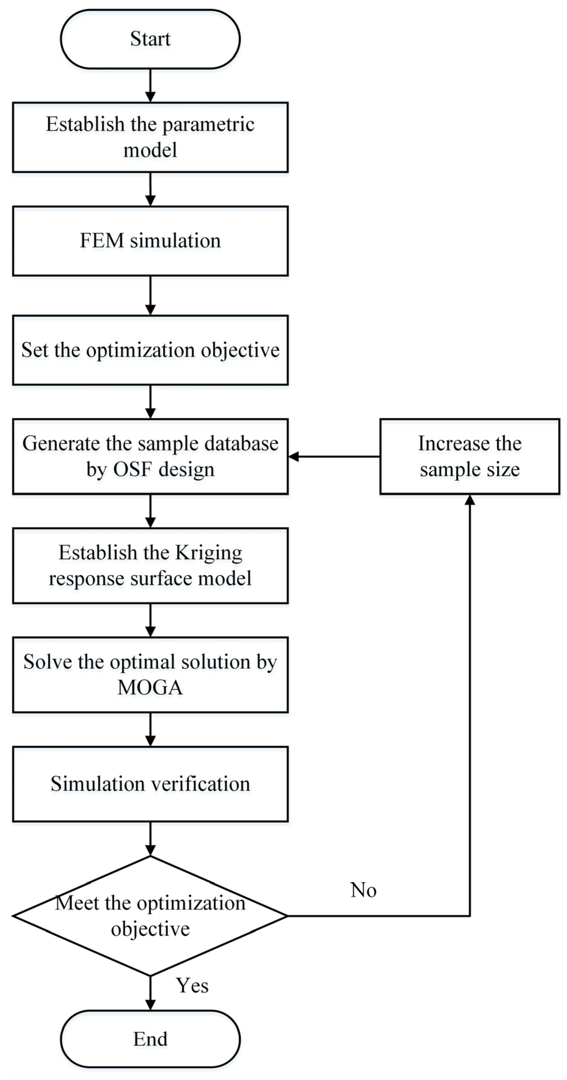
A neck structure optimal design method for the turbine wheel was proposed, as shown in
Figure 2. Step 1: first, the parametric model of the neck structure turbine wheel is established, and six structural parameters are selected to be optimized. Step 2: FEM simulation is conducted. Step 3: afterwards, three target parameters are selected, and the optimization objective is set. Step 4: the uniform sample database is generated by the optimal space-filling (OSF) design. Step 5: the Kriging response surface model is then established to characterize the relationship between the target and structure parameters. Step 6: the optimal solution is solved by the multi-objective genetic algorithm (MOGA), and the optimized structural parameters are obtained. Step 7: FEM simulation is conducted for the neck structure turbine wheel with the optimized structural parameters, and the simulation results of the target parameters are obtained. Step 8: last, the simulation results and optimization objectives are compared. If the simulation results meet the optimization objectives, the optimization is finished; otherwise, the sample size is increased, and Steps 4 to 7 are repeated until the simulation results meet the optimization objectives.
2.1. Parametric and Finite Element Model
To improve optimization efficiency, the parametric model of the neck structure turbine wheel is carried out. Twelve structure parameters (L1-L11 and
) at the neck for the turbine wheel are shown in
Figure 3. L1, L2, L3, L4 and L5 are the same length as L10, L9, L8, L7 and L6, respectively. L11 is the minimum distance at the neck, and
is the angle between L3 and L8. Therefore, six structure parameters (L1, L2, L4, L5, L11 and
) are selected to be optimized as P1–P6, as shown in
Figure 3.
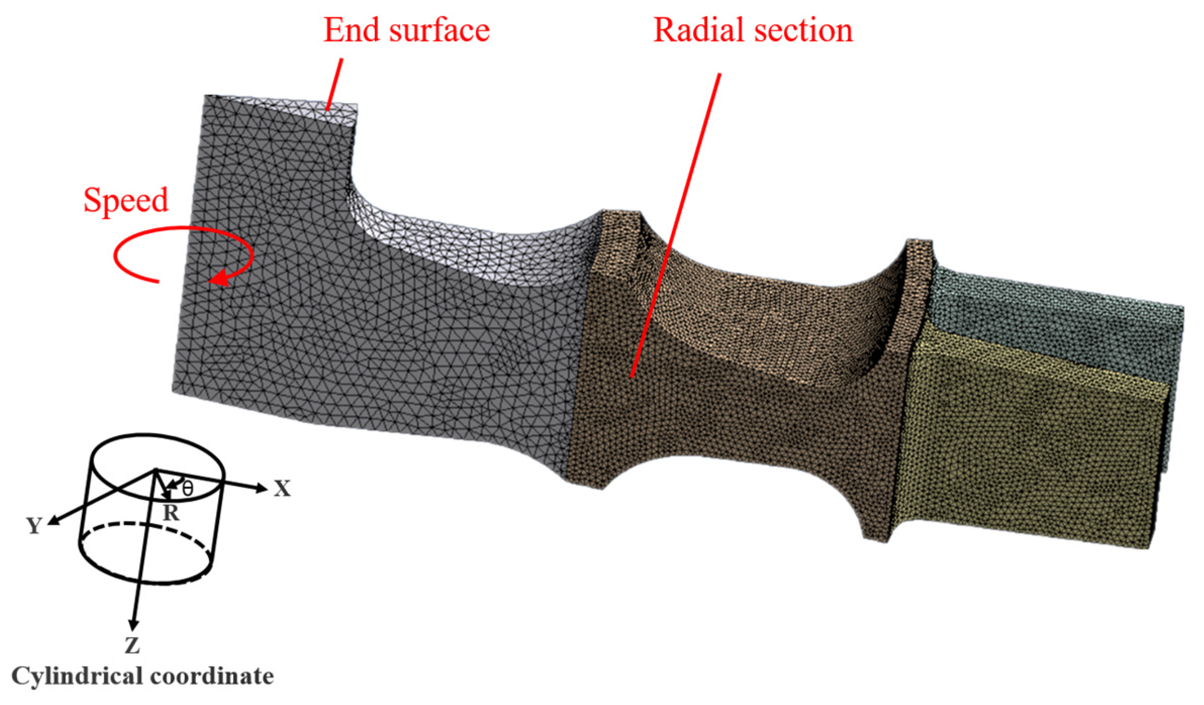
To reduce the calculation cost, the finite element model of the neck structure turbine wheel with two straight blades is established, as shown in
Figure 4. The blade shape has great effect on the aerodynamic performance, but has little effect on the containment of turbine wheel. Therefore, the real blades are replaced by the straight blades, and the rotational inertia of the wheel with the straight blades is same as that with the real blades. The neck structure turbine wheel is meshed by the tetrahedral solid element. The mesh sizes of the blades, the neck part and central part of the wheel are 0.5 mm, 0.5 mm and 1 mm, respectively. The end surface is constrained in displacement in the axial and radial directions. The two radial sections are constrained in displacement in the circumferential direction. Titanium alloy TC4 (in Chinese) is chosen for the turbine wheel, and the material parameters are listed in
Table 1. The bilinear elastic–plastic material model is adopted, and the tangent modulus is 1886 MPa.
In the condition of the clutch connect failure, the air turbine starter may experience operation at a turbine free run speed, in which the turbine wheel operates without a resistive load on the output shaft, causing the turbine to accelerate to a high speed. To ensure the turbine wheel does not burst at the turbine free run speed, the safety margin is design as 1.15 by considering the material property dispersion, machining error and operation temperature of the turbine wheel. For a certain type of air turbine starter, the turbine free run speed is 78,000 r/min, and the burst speed is designed as 89,700 r/min (1.15 times the turbine free run speed). Therefore, the rotating speed is set to 89,700 r/min here for the burst speed calculation.
2.2. Optimization Objective
To break the turbine wheel at the neck, the maximum radial stress
at the target speed should reach the tensile strength
, while the maximum circumferential stress
and maximum equivalent stress
are less than
. Therefore,
,
and
are selected as target parameters P7 to P9, and the optimization objective is set as:
When the maximum radial stress reaches the tensile strength, the smaller the maximum circumferential stress is, the easier it is to control the turbine wheel breaks at the neck cylindrical section. Therefore, a scaling factor is introduced. Without loss of generality, the value of starts from 1.1, and increases by 0.1 (i.e., 1.1, 1.2, 1.3, 1.4, 1.5……) until the optimal solution cannot be solved.
2.3. Optimization Process
The optimization process flowchart is shown in
Figure 5. First, the design variables (P1–P6) and variation range that need to be optimized are defined, and the parametric modelling is carried out. Then, FEM simulation is conducted and the target parameters (P7–P9) are selected. The sample database, which consists of P1 to P9, is generated by using the OSF design method. Based on the sample database, the Kriging response surface model is established to obtain the relationship between the target parameters (P7–P9) and structure parameters (P1–P6). Then, the optimization objective and constraints are set. At last, the optimal structural parameters are obtained by using the MOGA after 100 iterations.
The initial value and variation range of the structural parameters are listed in
Table 2. The closer to the rim, the greater the centrifugal force. In addition, the structural parameters close to the wheel rim (P3, P4 and P5) have a greater effect on the target parameters than the structural parameters far from the wheel rim (P1). Therefore, the variation ranges of P3, P4 and P5 are set to 2 mm, while that of P1 is set as 1 mm. The larger variation ranges of P2 and P6 (4 mm and 12°) are set to ensure the optimal structure can be formed.
The OSF design and Kriging response surface model have a high precision for multi-dimensional integration problems [
23,
24]. Six structural parameters (P1–P6) need to be optimized, therefore, the OSF design and Kriging response surface model are adopted.
The Kriging approximate model is a model based on structural analysis and variogram theory to perform unbiased optimal estimation of regionalized variables in a limited region, and can be used to solve problems with a high degree of nonlinearity to obtain the ideal fitting effect [
24]. This method is suitable in the case of a small sample point disturbance, and the calculation speed of this algorithm is faster than other methods. Compared with other approximate models such as nonlinear regression, neural network and sparse grid, the Kriging approximate model is used in fewer occasions and corresponds to the corresponding sample point generation methods. Since the data points in the OSF sample library need to be calculated by finite elements and evaluated by error, the results of the sample library have a high accuracy. It means that compared with the fitting method, the interpolation method is better, so the Kriging method is adopted to generate the response surfaces.
To ensure the precision of the calculation, the fourth-order polynomial is adopted for the Kriging response surface model. The minimum sample number of the fourth-order model can be determined by [
25]:
where the number of optimized parameters is
N = 6.
The minimum sample number
Kmin = 40, therefore, 45 samples are selected for the Kriging response surface model. The sample number of OSF design depends on that of the Kriging response surface model, therefore, 45 samples are selected for the OSF design. According to
Table 2, a uniform sample database with 45 samples is generated by employing the OSF design, and every sample includes six structural parameters (P1–P6) and three target parameters (P7–P9), as list in
Table 3.
The Kriging response surface model is established to characterize the relationship between the target parameters and structure parameters, and can be expressed as:
where
f(
x) are the object functions (i.e., three target parameters P7–P9),
y(
x) are the fourth-order polynomial functions correspondence with six structural parameters (P1–P6) and
z(
x) is the deviation of the results between the Kriging response surface model and FEM simulation.
MOGA [
26] is a multi-objective iterative genetic algorithm, which sorts all individuals in a population based on the basic principle of Pareto Optimality, and carries out selection operations in the evolution process on the arranged order. This will make the first Pareto best individuals have a greater probability of inheriting to the next generation. After many algebraic cycles, the optimal Pareto solution of multi-objective optimization problem can be finally obtained. This method is suitable for multi-objective optimization problems, the optimal design of global search and the response surface model. Therefore, MOGA is adopted in this paper.
Based on the Kriging response surface model, the optimal solution (the optimized structural parameters) is solved by employing the MOGA algorithm to meet the optimization objective. In addition, the optimized structural parameters (P1-P6) are obtained as listed in
Table 4. It should be noted that when λ > 1.5, the optimal solution cannot be solved, which means that no turbine wheel structure can make λ greater than 1.5.
2.4. Sensitivity Analysis
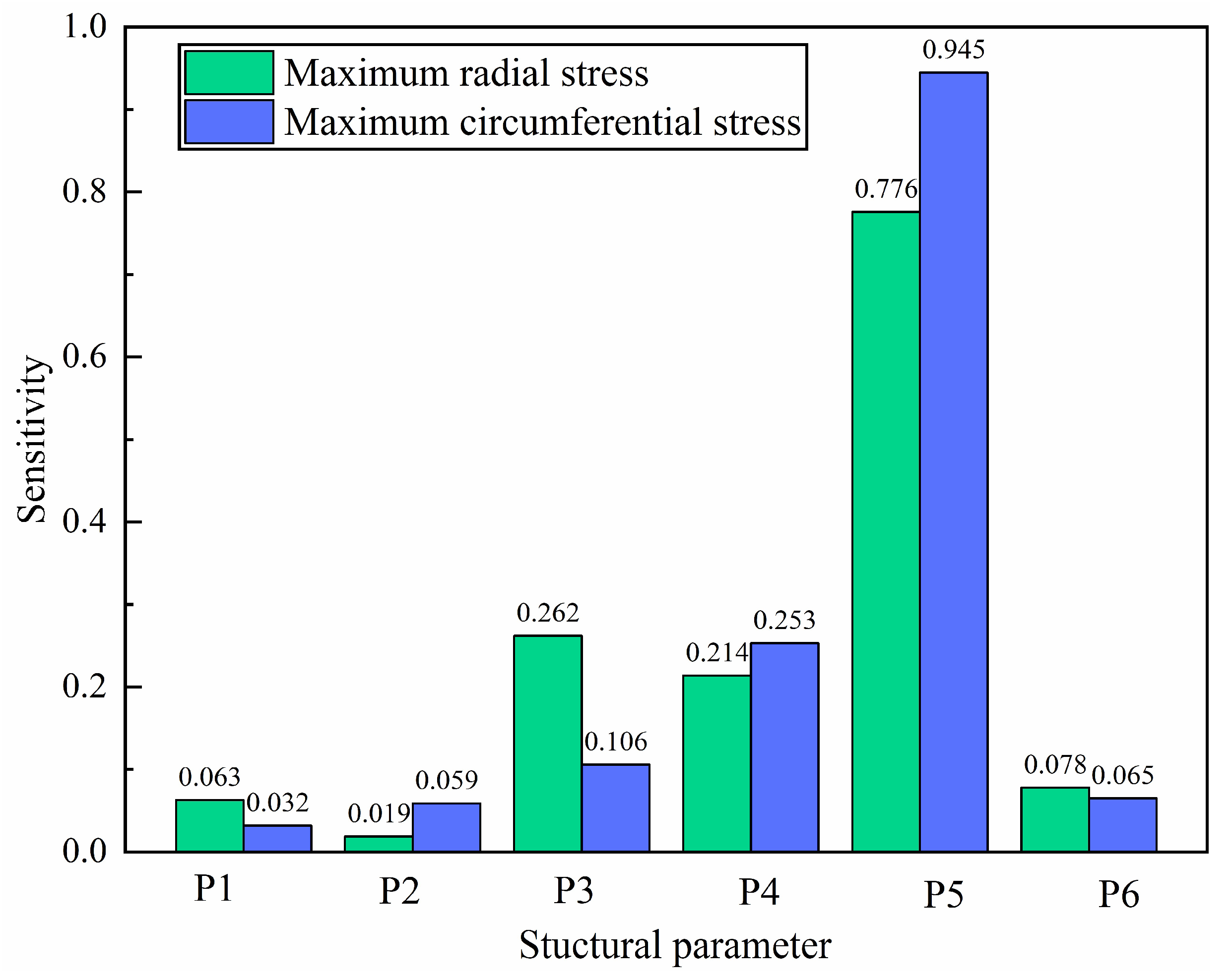
To study the effect of the structural parameters on the target parameters, a sensitivity analysis between the target and structural parameters was conducted. The sensitivities of six structural parameters on the maximum radial and circumferential stress (
and
) are shown in the
Figure 6.
Figure 6 shows that the sensitivities of P5 on
and
(0.776 and 0.945) are the maximum, which means that the minimum distance at the neck effects most on the target parameters.
Figure 6 also shows that the sensitivities of P3, P4 and P5 are larger than 0.1, whereas that of P1, P2 and P6 are less than 0.08. It means that the structural parameters close to the wheel rim have a greater effect on the target parameters than the structural parameters far from the wheel rim. The results verify the rationality of variation range of the structural parameters in
Section 2.3.
2.5. Simulation Verification
According to Equation (3), a deviation exists between the Kriging response surface model and FEM simulation, therefore, the FEM simulation needs to be conducted to verify the optimized structural parameters. According to the optimized structural parameters, FEM simulation is conducted and the simulation results are shown in
Table 5 and
Table 6.
Table 5 is simulation result of the target parameters.
Table 5 shows that P8 and P9 are less than
, and the errors of P7 are less than 1.5%. It means that the target parameters meet the optimization objective (Equation (1)), which verifies the optimized structural parameters in
Table 4.
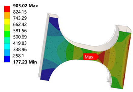
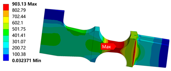
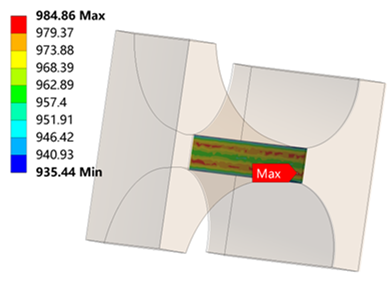
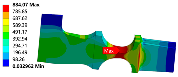
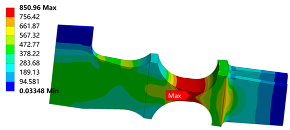
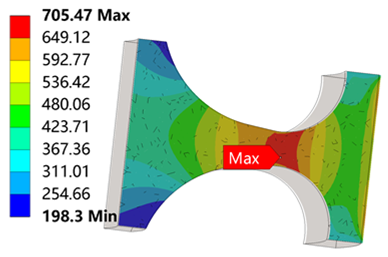
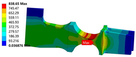
Table 6 is the stress distribution of the turbine wheel.
Table 6 is the stress distribution of the turbine wheel.
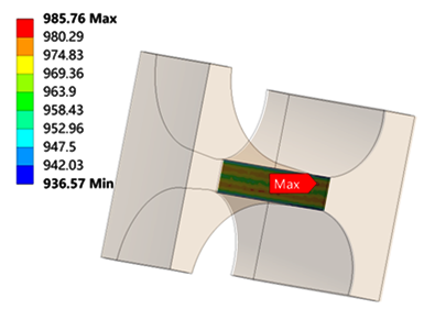
Table 6 shows that when λ = 1.1, the radial stress at the neck is 986 MPa, which reaches the tensile strength
. The circumferential stress and equivalent stress at the neck are 905 MPa and 903 MPa, which are less than the radial stress. It means that the turbine wheel with λ = 1.1 breaks in the neck along the circumferential direction. The stress distributions for λ = 1.2, 1.3, 1.4 and 1.5 are similar to λ = 1.2.
Table 6 also shows that the maximum radial stress, circumferential stress and equivalent stress occur at the neck, which proves the correctness of the simulation results.
It should be noted that the larger λ is, the more easily the turbine wheel breaks at the neck. However, a turbine wheel structure with a large λ is hard to process. Considering the processing cost, the optimized structural parameters for λ = 1.2, 1.3 and 1.4 can be adopted as design parameters.
4. Effect of Turbine Wheel Burst Modes on Containment
According to
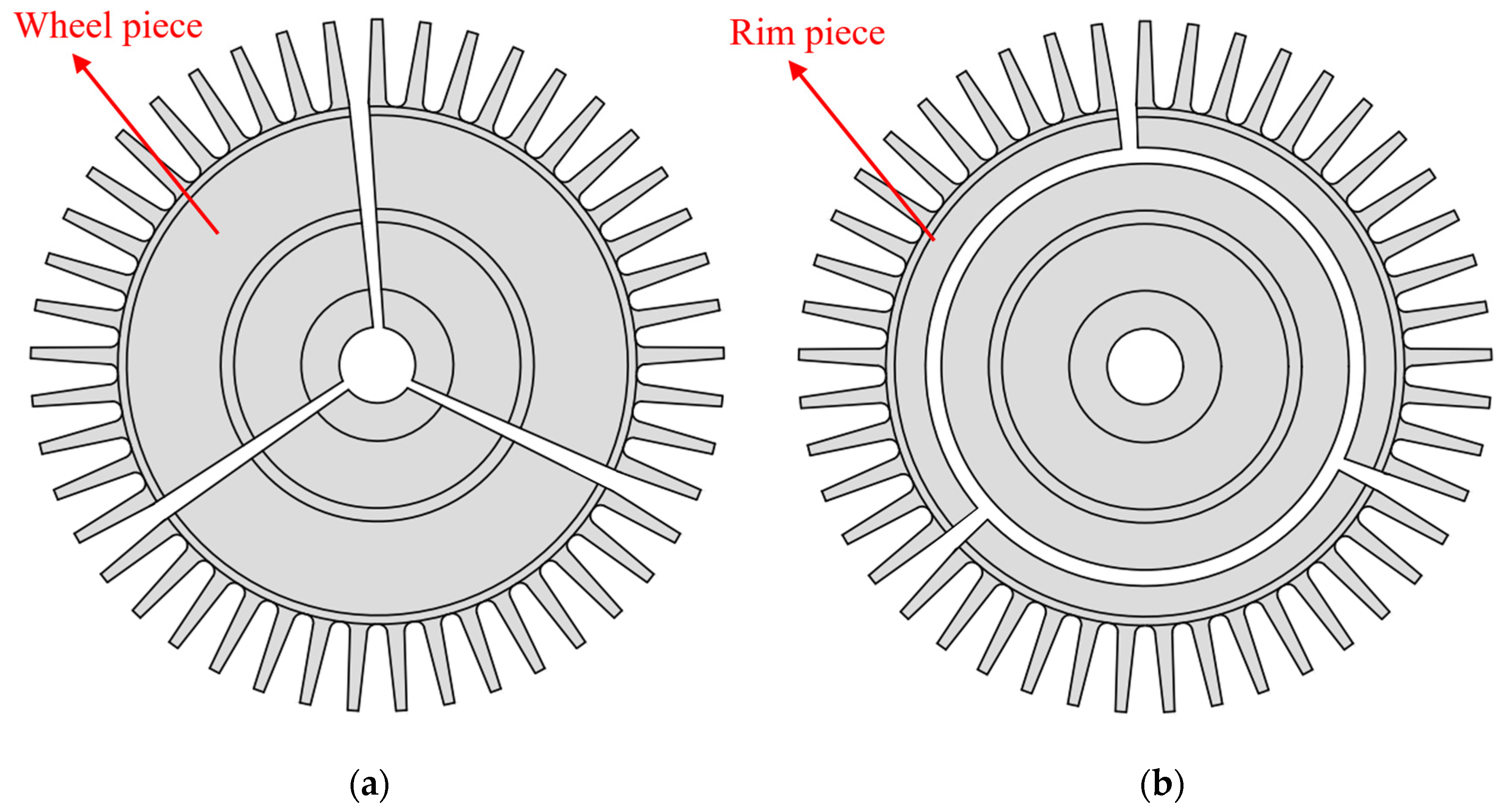
Section 3.3, the rim burst of the turbine wheel can greatly reduce the requirement for the thickness of the containment ring. To quantitatively investigate the effect of turbine wheel burst modes on the containment, the containment tests for different turbine wheel burst modes (the wheel burst and the rim burst) are simulated. The turbine wheel burst modes are shown in
Figure 14.
Focusing on the wheel burst, the containment simulation for the trisection wheel burst is conducted, because the impact energy is at a maximum when the wheel is broken in three equal pieces [
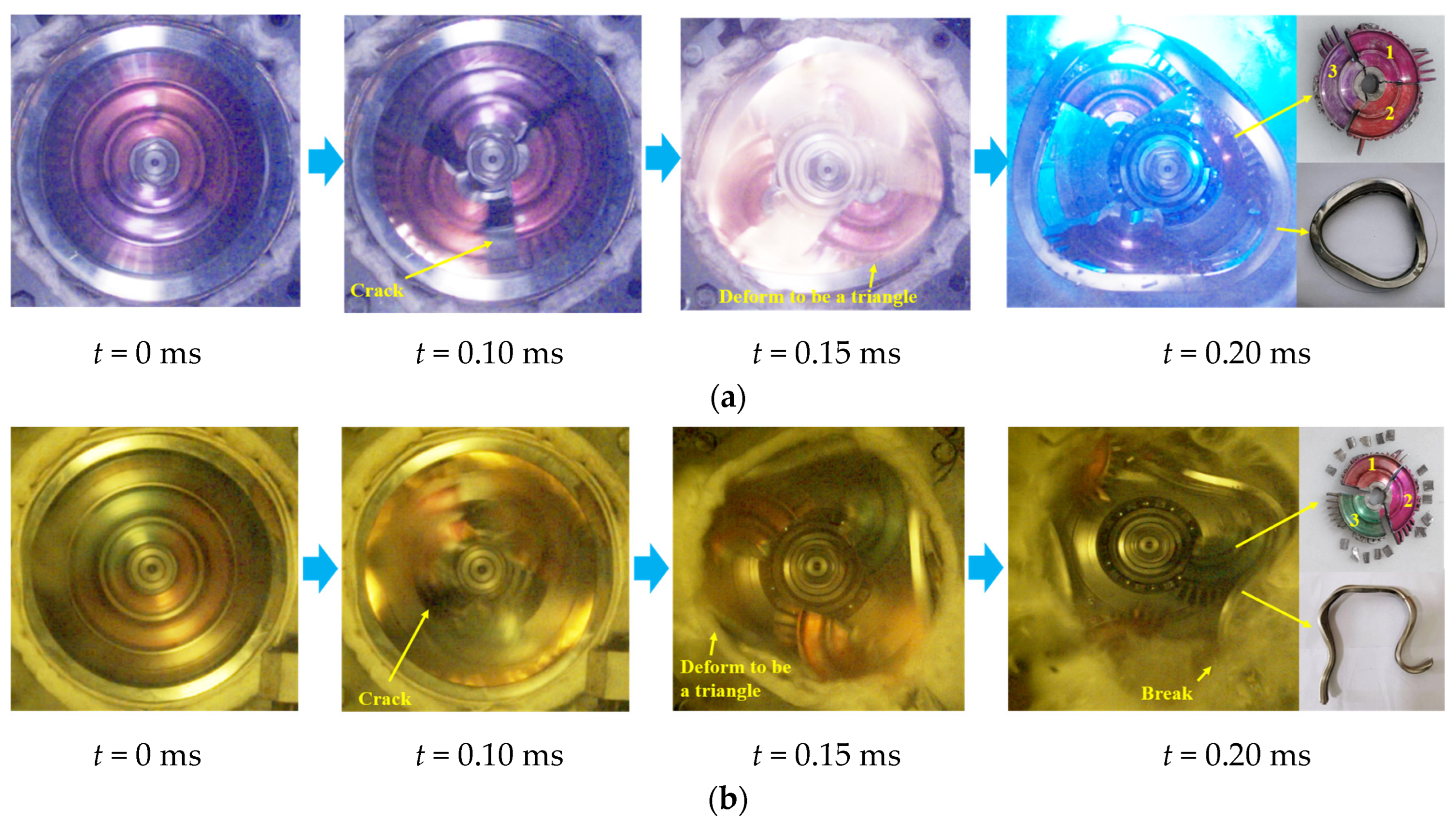
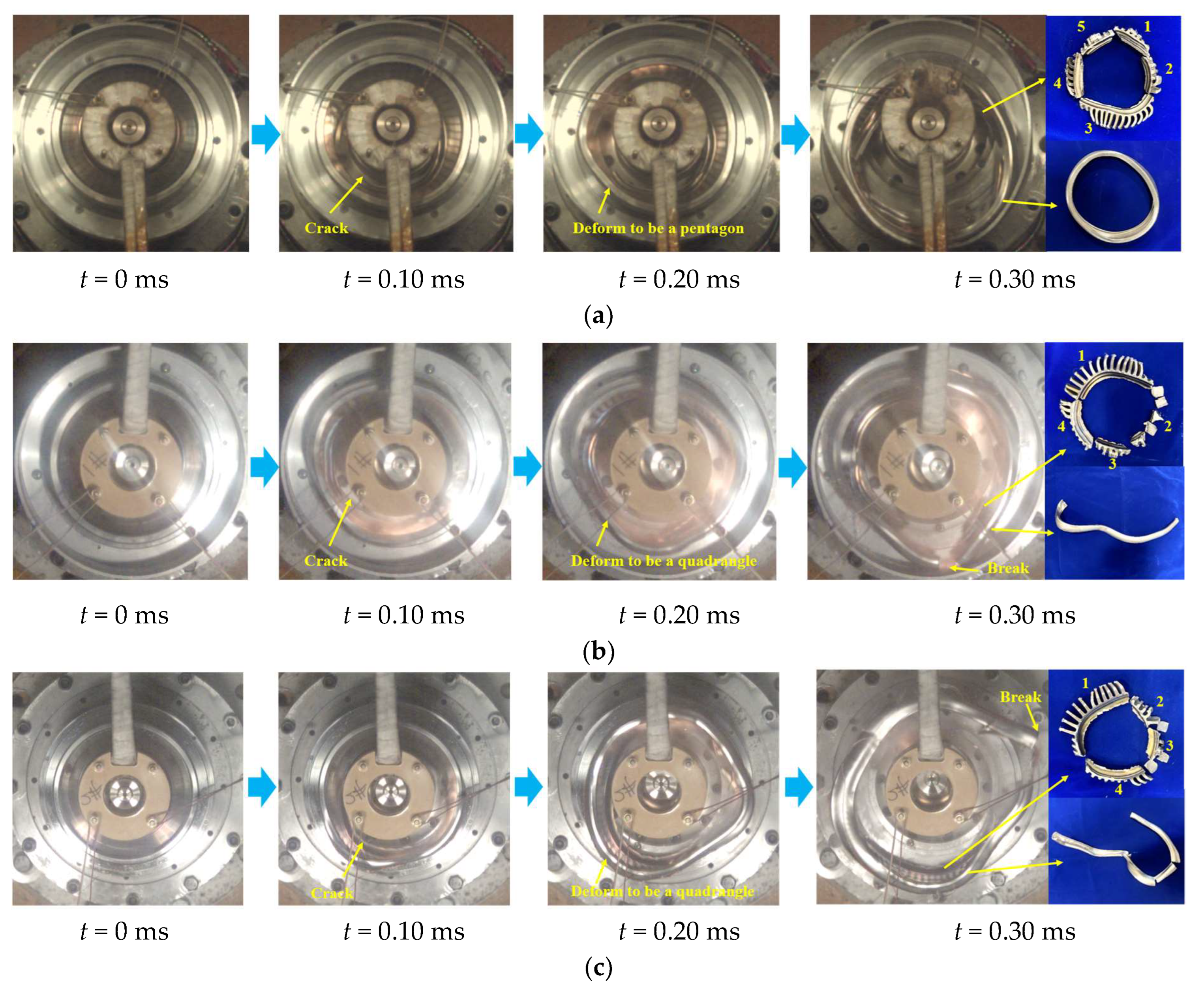
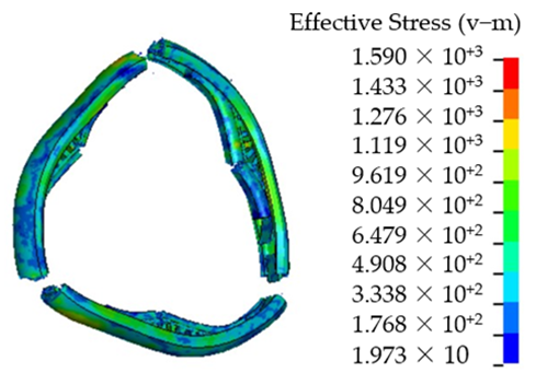
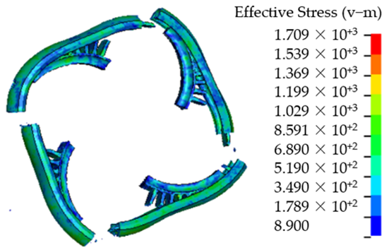
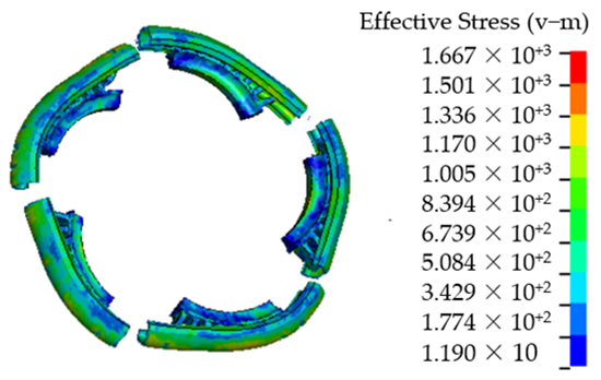
8]. Focusing on the rim burst, the containment simulations for the trisection, quarter and quintile rim burst are conducted. A trisection rim burst is investigated because the impact energy is at a maximum when the rim is broken in three equal pieces in the case of the rim burst. The quintile rim burst is investigated because the experimental results of the burst mode (as shown in
Figure 9d,
Figure 10d and
Figure 11d) are a five piece burst of wheel rim. A quarter rim burst is studied for comparison.
4.1. Material Model
The containment ring and turbine wheel adopted the nickel-based alloy GH4169 and titanium alloy TC4, respectively. The Johnson–Cook (J-C) model [
27,
28] considers the effect of the strain rate on the material, and is therefore adopted for the containment ring and turbine wheel. The J-C model parameters of the two components are listed in
Table 7. The detail information for the values of J-C model parameters can be found in our previous work [
29].
4.2. Finite Element Model and Boundry Conditions
The finite element models of the turbine wheel, wheel rim and containment ring are shown in
Figure 15. The geometric sizes of the neck structure for the turbine wheel and wheel rim are shown in
Figure 3. The critical thicknesses of the containment ring for different turbine wheel burst modes are listed in
Table 8.
T denotes the thickness of the containment ring. To obtain the critical thickness, T is first estimated by the potential energy method [
8] and then the containment simulation is conducted with the estimated thickness. If the containment ring breaks, the thickness is increased by 0.2 mm until the containment ring does not break; if the containment ring does not break, the thickness is decreased by 0.2 mm until the containment ring breaks. To verify the critical thickness of the containment ring, four thicknesses (0.2 mm less than the critical thickness) of the containment ring are taken for comparison, as listed in
Table 8.
The turbine wheel and wheel rim are meshed by the tetrahedral solid element and the mesh size is 1 mm. The containment ring is meshed by the hexahedral solid element and the mesh size is 1 mm. The free boundary is adopted for the containment ring, which is consistent with the actual situation.
In the condition of the clutch disconnect failure, the air turbine starter is driven in reverse by the aeroengine and the experience operation at a higher speed (larger than the turbine free run speed). It leads to the failure of the support bearings, thus allowing axial travel of the turbine wheel. The turbine rim cutter is located in the air turbine starter, and the axial travel of the turbine wheel results in contact between the turbine wheel and the turbine rim cutter. For the contact position of the turbine wheel, the temperature sharply rises. It leads to the rapid reduction of the material property, thereby realizing the rim burst. The burst speed is designed as 1.05 times the turbine free run speed by considering the turbine bearing strength. For a certain type of the air turbine starter, the turbine free run speed is 78,000 r/min, so the burst speed is designed as 81,900 r/min (1.05 times the turbine free run speed).
4.3. Containment Simulation for the Wheel Burst
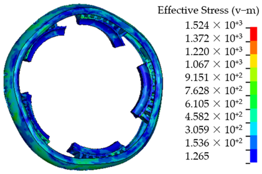
Figs. 16 and 17 are the process of the turbine wheel pieces impacting the containment ring with T = 7.8 mm and T = 7.6 mm, respectively.
Figure 16 shows that when
t = 0.09 ms, the turbine wheel pieces first contact the containment ring, and the containment ring starts to deform. When
t = 0.30 ms, the containment ring deforms plastically to absorb the impact energy, and its shape tends to be the triangular. When
t = 0.50 ms, the turbine wheel pieces stop impacting the containment ring, and the containment ring fully deforms to be the triangle.
Figure 17 shows that when
t = 0.09 ms, the turbine wheel pieces first contact the containment ring, and the containment ring starts to deform. When
t = 0.15 ms, the containment ring fully deforms plastically to be the triangle, but its absorbed energy is less than the impact energy of the turbine wheel pieces, and thereby the containment ring starts to break. When
t = 0.50 ms, the containment ring breaks into three pieces. The simulation results illustrate that T = 7.8 mm is the critical thickness of the containment ring for the trisection wheel burst.
4.4. Containment Similation for the Rim Burst
The impact processes of the trisection, quarter and quintile rim burst are similar with that of the trisection wheel burst.
Table 9 is the containment simulation for the three rim burst modes.
Table 9 shows that the containment rings fully deform plastically to be the triangle, quadrangle and pentagon for the trisection, quarter and quintile rim burst, respectively. The containment rings with comparative thicknesses break, because their absorbed energy is less than the impact energy of the wheel rim pieces. The simulation results illustrate that T = 5.5, 5 and 4 mm are the critical thicknesses of the containment rings for the trisection, quarter and quintile rim burst.
4.5. Comparison between Different Burst Modes
The simulation results for different burst modes with the critical thicknesses are compared.
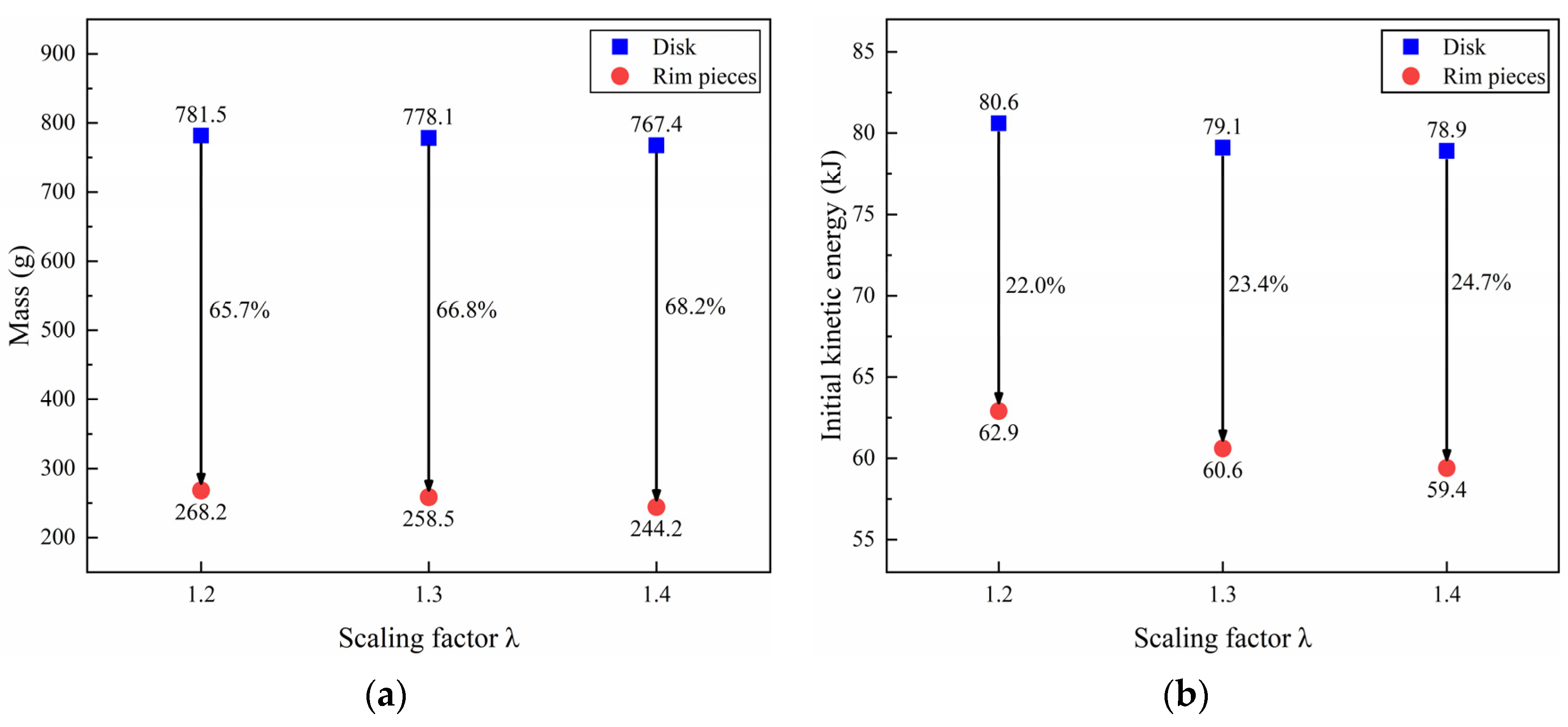
Figure 18 is the comparison of the initial kinetic energy of pieces for different burst modes.
Figure 18 shows that compared with the trisection wheel burst (60.2 kJ), the initial kinetic energy of pieces for rim burst (45.3 kJ) decreases dramatically by 24.8%.
Figure 19 is the comparison of the critical thickness of the containment ring for different burst modes.
Figure 19 shows that compared with the trisection wheel burst (7.8 mm), the critical thicknesses of the containment ring for the trisection, quarter and quintile rim burst (5.5, 4.5 and 4.0 mm) decrease dramatically by 29.5%, 42.3% and 48.7%, respectively.
Figure 19 also shows that for the rim burst modes, the more pieces the wheel rim breaks, the smaller the critical thickness of the containment ring is. The simulation results from Figs. 18 and 19 mean that compared with the wheel burst, the rim burst can dramatically decrease the initial kinetic energy of pieces and the critical thickness of the containment ring, and thereby reduce the mass of the containment ring.
Figure 20 is the comparison of the change rate of the containment ring diameter for different burst modes.
Figure 20 shows that the change rates of the containment ring diameter for all burst modes are larger than 13.0%, which means that the containment rings are fully deformed.
Figure 20 also shows that the change rates of the containment ring diameter for the trisection, quarter and quintile rim burst are 13.1%, 14.0% and 14.9%, respectively. It means that the change rate of the containment ring diameter increases with the increase of the number of the wheel rim pieces.
6. Conclusions
Based on an OSF design, Kriging response surface model and MOGA algorithm, a neck structure optimal design method was proposed for the turbine wheel, and verified by the rotor over-speed burst test. Then, the effect of turbine wheel burst modes on the containment was investigated quantitatively and verified by the containment tests of different burst modes. Based on the experimental and simulation results, the containment design method was proposed for the neck structure turbine wheel. Some key conclusions of this work can be summarized as follows:
- (1)
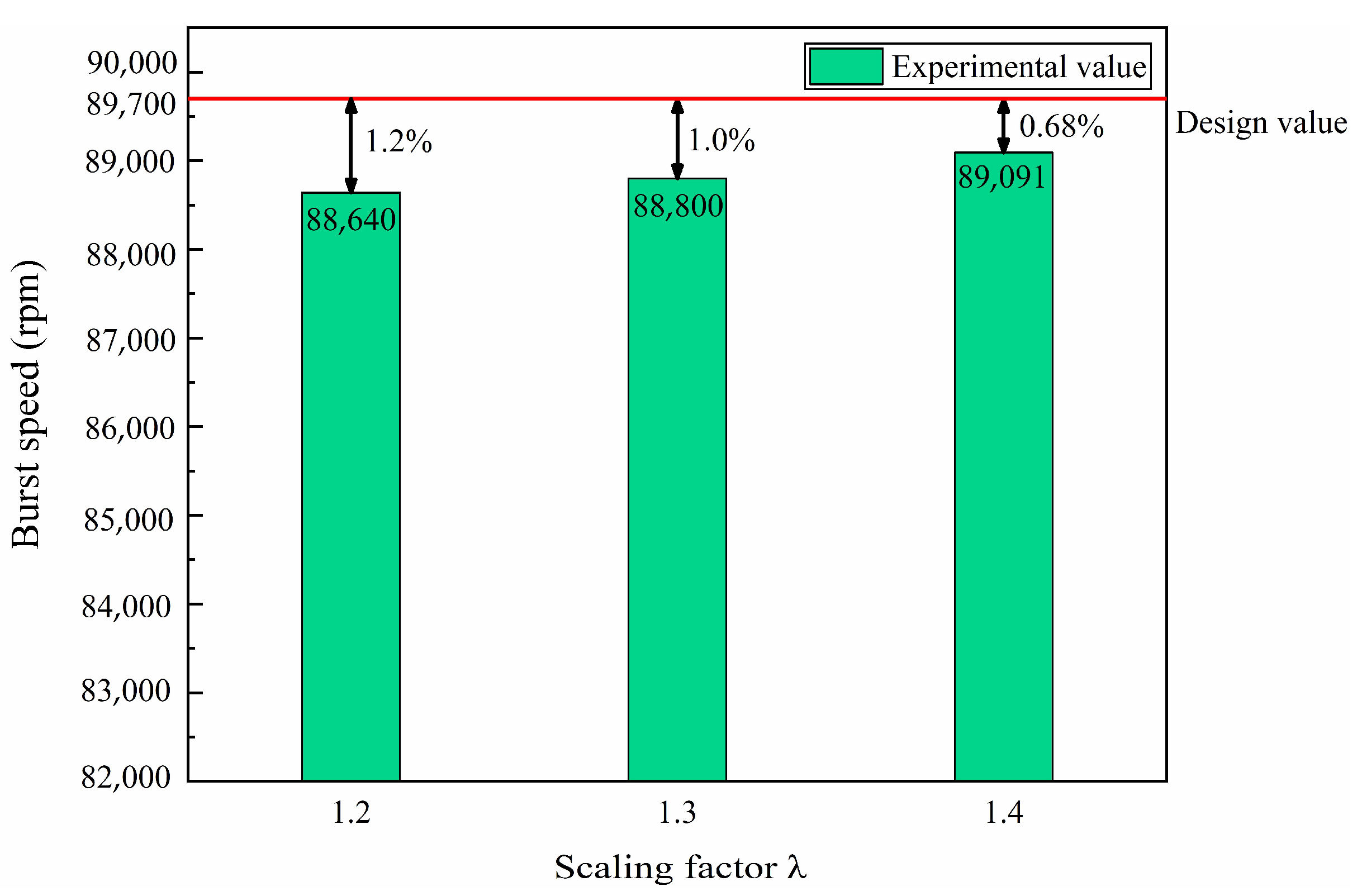
Six structure parameters of the neck structure turbine wheel are optimized by the optimal design method, and the optimal structural parameters with the scaling factor λ = 1.2, 1.3 and 1.4 are obtained. The maximum errors of the burst speeds between the over-speed burst experimental and design values are less than 2%, and the neck structure turbine wheel breaks in the neck, validating the accuracy of the optimal design method proposed in this paper.
- (2)
Compared with the trisection wheel burst (60.2 kJ), initial kinetic energy of pieces for rim burst (45.3 kJ) decreases dramatically by 24.8%. Compared with the trisection wheel burst (7.8 mm), the critical thicknesses of the containment ring for the trisection, quarter and quintile rim burst (5.5, 4.5 and 4.0 mm) decrease dramatically by 29.5%, 42.3% and 48.7%, respectively.
- (3)
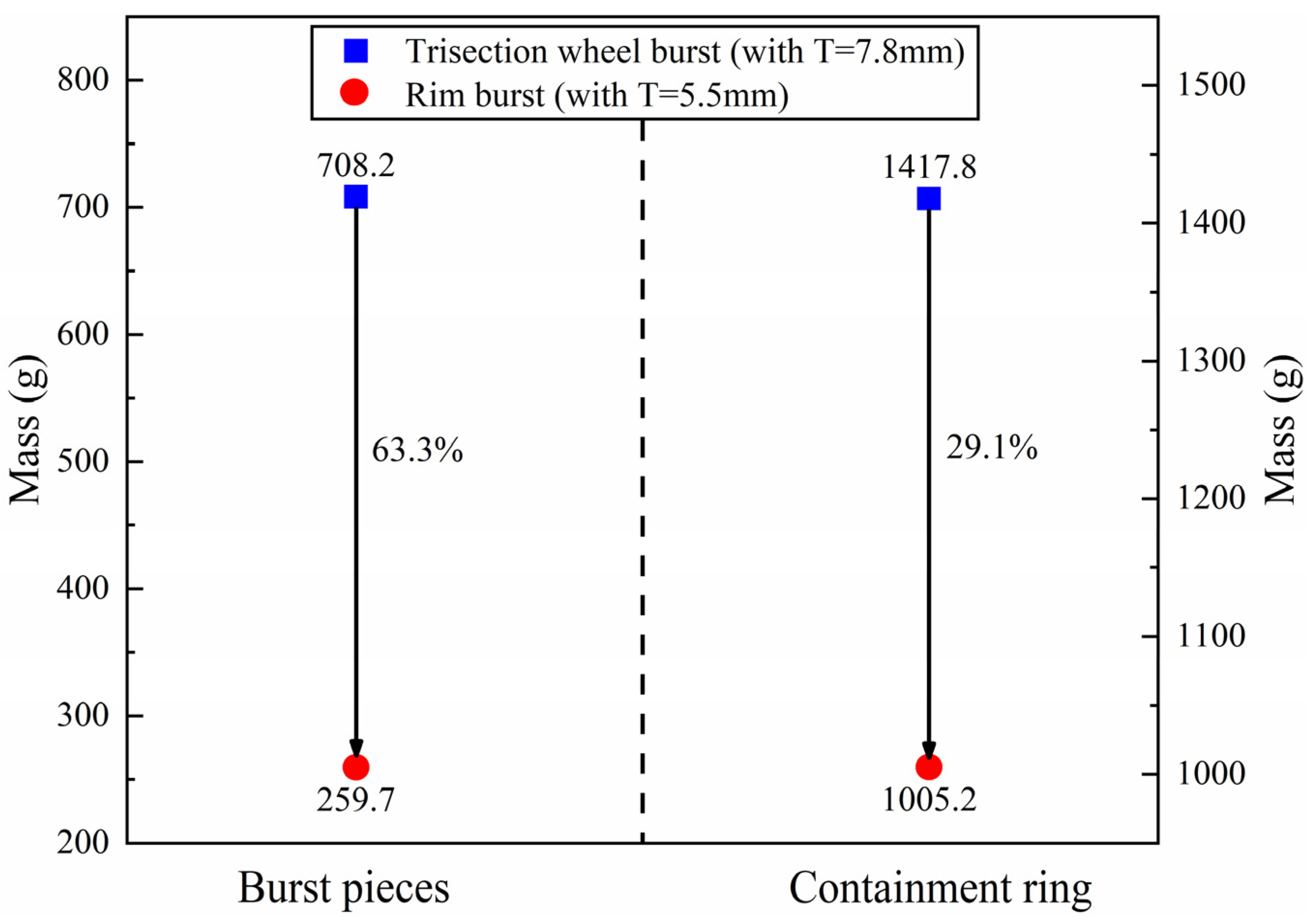
For the neck structure turbine wheel, the mass and initial kinetic energy of the rim pieces are 257.9 g and 45.3 kJ, respectively. Compared with the trisection wheel pieces, the mass and initial kinetic energy of the rim pieces decrease dramatically by 63.3% and 24.8%, respectively. As a result, the thickness and mass of the containment ring decrease greatly by 29.5% and 29.1%, respectively. Therefore, the neck structure turbine wheel can dramatically decrease the mass and initial kinetic energy of the burst pieces from the wheel, thereby reducing the thickness and mass of the containment ring.
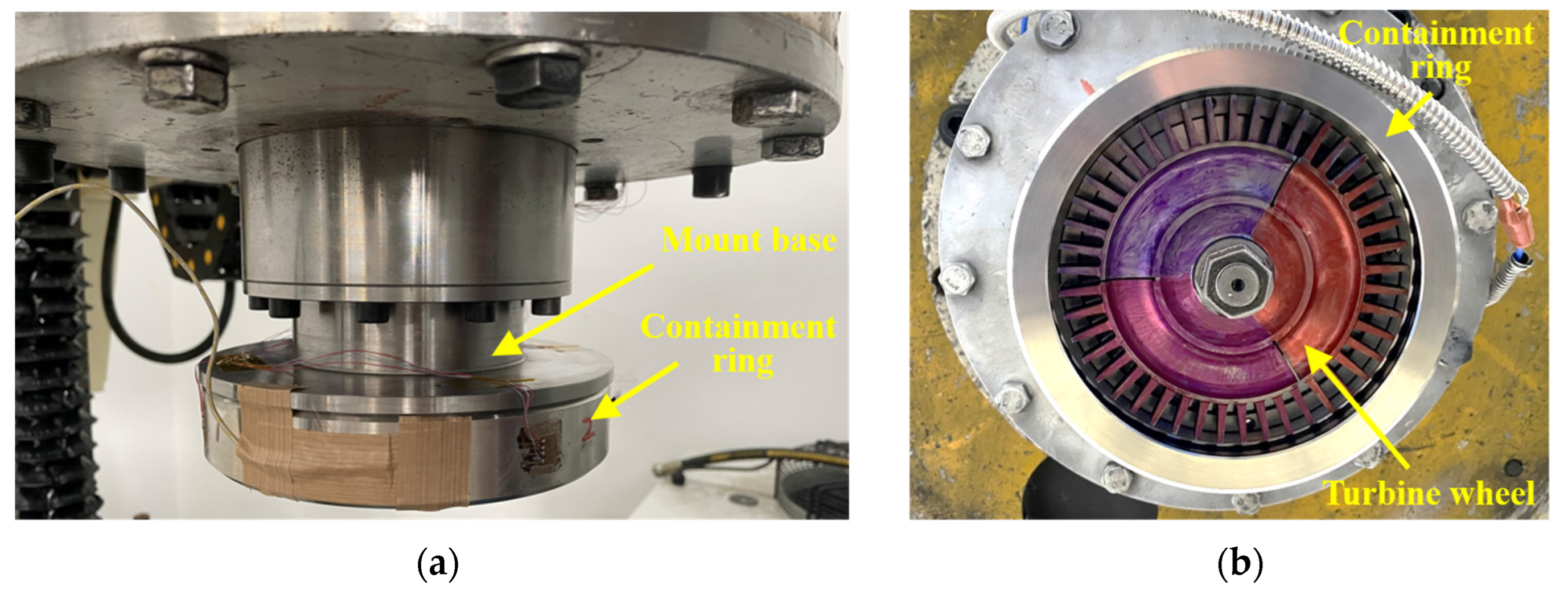
It is worth noting that the neck structure optimal design of the turbine wheel was verified by the component containment test. The component containment test is only composed of the turbine wheel and containment ring. However, the working condition of the whole air turbine starter is more complicated than that of the component containment test. In future research, the containment test of the whole air turbine starter will be conducted to verify the optimal neck structure turbine wheel, and the experimental results can guide the containment design of the in-service air turbine starter.
To ensure the computational precision and efficiency, the neck structure optimal design method employed the OSF design, Kriging response surface model and MOGA algorithm. However, the YUKI algorithm [
30] and Proper orthogonal Decomposition endorsed with Radial Basic Function (POD-RBF) [
31] were also proven to be effective computational-wise and used in dynamic analysis. In the future research, the YUKI algorithm and POD-RBF will be employed to optimize the neck structure turbine wheel, and the computational precision and efficiency between different optimization methods will be compared.

