Article

Experimental Investigation of Helicopter Noise While Approaching an Elevated Helipad

Dipartimento di Scienze e Tecnologie Aerospaziali, Politecnico di Milano, Via La Masa 34, 20156 Milan, Italy
*
Author to whom correspondence should be addressed.
Aerospace 2023, 10(8), 701; https://doi.org/10.3390/aerospace10080701
Submission received: 9 June 2023 / Revised: 3 August 2023 / Accepted: 8 August 2023 / Published: 9 August 2023
(This article belongs to the Special Issue Propeller Noise)

Abstract

:
The present paper describes a test campaign performed to investigate the noise footprint emitted by a helicopter in an idealised urban context, reproducing the approach to an elevated helipad. The test campaign was performed in Politecnico di Milano’s anechoic chamber and was finalised to investigate the effects produced only by helicopter noise. The set up consisted of a two-blade main rotor helicopter model and an aluminium rectangular prism model reproducing the landing building. Ground observer perceptions were recorded by means of a surface microphone and a realistic landing trajectory was approximated as a succession of fixed point measurements. Collected data were analysed through acoustic spectra and sound maps. Spectra were used to comprehend physical phenomena, such as reflection, diffraction and shielding, and to analyse the different contributions of helicopter noise. A sound map analysis enabled us to obtain a global perspective of the involved phenomena and to understand th extent to which people close to a building are stressed by a helicopter approaching an elevated urban helipad. Moreover, the experimental database, obtained over a free geometry, can be considered a useful tool for the validation of aeroacoustic solvers with different levels of fidelity.

1. Introduction

Uncomfortable noise related to helicopter traffic over metropolitan areas is particularly critical in the phase of approaching and landing on helipads on building roofs. A good knowledge of the physics involved in related phenomena could lead to defining better flight procedures and also to improving building design from this point of view. Furthermore, a deeper comprehension of interaction phenomena would help in improving existing computational codes for aeroacoustic simulations [1,2]. Indeed, urban traffic of VTOL aircraft is expected to grow rapidly in the future due to the increased interest in the design of novel electric Vertical Take-Off and Landing (eVTOL) aircraft for Advanced Air Mobility (AAM); this will also impact city planning criteria. Investigations into understanding noise pollution produced by rotary wing aircraft in the urban context have used various different methods of testing, both experimental and analytical. Rules on maximum exposition levels permitted in urban areas are also based on these studies, with some differences related to their classes, e.g., residential, industrial, or commercial.
Considering full size experimental campaigns, a series of tests held in the United States in the late 1990s tried to understand how much landing a helicopter can be considered a disturbance depending on the perception of each person. A technical report by Schomen, Hoover and Wagner [3] had the objective of evaluating A-Weighted systems. This weighting function tries to simulate the behaviour of the human ear, and to show how sensitive it is to various frequencies. A further similar test campaign was conducted by Ahuja et al. [4] for an S-76 landing on the rooftop of a building. Microphones were positioned in one hundred locations near buildings, where the SPL (Sound Pressure Level) was measured during the helicopter’s approach. Measurements results showed that the effects of shielding and reflection of sound waves by nearby buildings are clearly visible depending on the observer’s height. Several researchers focused their attention on noise in designated places such as schools, where noise should be lowered as much as possible. Hilton and Pegg [5], in a study performed for NASA, conducted tests on noise perceived by some classes in a school after a flight by a patrol helicopter used by the police department at an altitude of 150 m. Although the noise detected outside was beyond the tolerance level prescribed in law, the walls of the building had a sufficient shielding effect. Indeed, the noise was reduced by at least 20 dB, and at higher frequencies, filtering was even more effective. This action guaranteed a quite acceptable noise level during lessons, even if patrol activity went on for several minutes.
Full-size tests are not always possible and could require a very high effort. Thus, the use of scaled models in wind tunnels under monitored and controlled conditions can also be considered a valuable tool for validation of numerical simulation software. In particular, anechoic chambers, which completely isolate the test section from acoustic noise, are widely used for aeroacoustic measurements of rotorcraft configurations. Doolan and Leclercq [6] conducted tests in an anechoic wind tunnel to verify the effect of the aerodynamic interference phenomenon between the helicopter main rotor and the tail rotor, known as the Orthogonal Blade Vortex Interaction (OBVI), on the acoustic spectrum. This work showed the impact that this phenomenon has on pressure variations and on blade local airloads, considerably contributing to the noise spectrum. Feight et al. [7] used an anechoic chamber to study the noise emission of a four-rotor drone during hovering. A comparison between measurements performed with different operating rotors allowed them to identify critical components in noise emission for this configuration. A further example of the use of an anechoic chamber is the test reported by Zawodny and Douglas [8], aimed at describing the acoustic behaviour of a rotary wing Unmanned Aircraft System (UAS) fuselage compared to a rotor operating alone. Moreover, Yang et al. [9] described an experimental investigation of a wavy rotor modified from the baseline rotor by shifting every other cross-section toward the trailing edge in order to alleviate the rotor noise of multi-copters. A great step forward in the study of noise scattering of helicopter rotors in the presence of a fuselage was provided by the activities conducted by the GARTEUR Action Group HC/AG-24 [10]. In particular, the Action Group focused on the development and validation of numerical prediction methods and the establishment of an experimental database for numerical validations.
As previously said, the interest in noise emission of multi-rotor configurations has grown in recent years due to the new challenges proposed by AAM and eVTOL configurations. For instance, Thai et al. [11] investigated the interactions of small hovering rotors using both simulations and experimental analyses conducted in an anechoic chamber. In particular, a dual rotor interaction was analysed by reproducing a pair of co-rotating rotors and a pair of counter-rotating rotors positioned at different separation distances. Jia and Lee [12] investigated the acoustics of a quad-rotor eVTOL using a high-fidelity simulation tool, finding that no rotor-to-rotor interaction could be identified due to the vertical separation distance between the front and rear rotors and due to the fact that the eVTOL fuselage does not have a significant impact on acoustics. However, both the rotor aerodynamics and acoustics were greatly influenced as the rotor size increased. Poggi et al. [13] presented a numerical investigation of the noise produced by two side-by-side propellers, showing that the blade tip Mach number strongly affects the magnitude and directivity of the radiated noise, while increasing the tip clearance leads to an increase in the spatial frequency of the noise directivity for both co-rotating and counter-rotating configurations. Recently, a great effort in the study of noise footprints related to multi-rotor configurations has been provided by the activities conducted in the GARTEUR Action Group HC/AG-26 [14], aimed at providing a comprehensive experimental database focused on propeller–propeller interactions for the validation of numerical solvers with different levels of fidelity.
In this framework, the present article describes experiments performed at Politecnico di Milano to evaluate acoustic noise in a semi-anechoic chamber on a test case reproducing a helicopter approaching an elevated helipad. The main goal of this activity is to collect valuable experimental data to comprehend physical phenomena, such as reflection, diffraction and shielding, related to acoustic emission of a rotor on descent toward a reflective surface and to analyse the different contributions to helicopter noise. Moreover, the novelty of the present activity is the use of a true rotor with a free geometry as an acoustic source. The test campaign enabled us to collect a valuable experimental database that can be considered a quite novel contribution in the acoustic research panorama, suitable for the validation of aeroacoustic solvers. With these aims, tests were conducted by using a small rotor model and a simple geometry building model to provide a completely open experimental database for numerical solver validation. The experimental set up did not include a tail rotor so that a non-negligible noise contribution was missing. Nevertheless, the main rotor remains the main noise source in reality, so this simple rig allowed for a clear identification of the main effects occurring in the helicopter test case. The use of such a test rig with respect, for instance, to tests using a small-size electroacoustic device as an acoustic source [10], makes it possible to obtain data regarding real physical phenomena related to this rotorcraft manoeuvre. Moreover, the use of simple scaled models for both the rotor and the building enabled us to collect experimental data which are usually collectable only by means of full-scale experiments, which are far more demanding in terms of cost and test facilities [5].
The paper is organised as follows. Section 2 provides a description of the experimental set up, including the rotor and building models, measurements techniques and test configurations. Section 3 presents the discussion of the main results obtained in the experiments. Conclusions are drawn in Section 4.

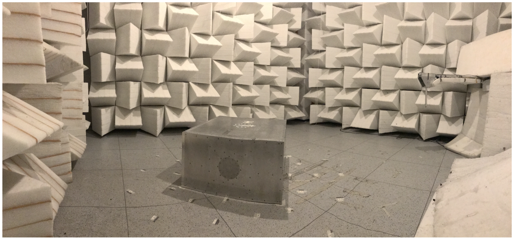
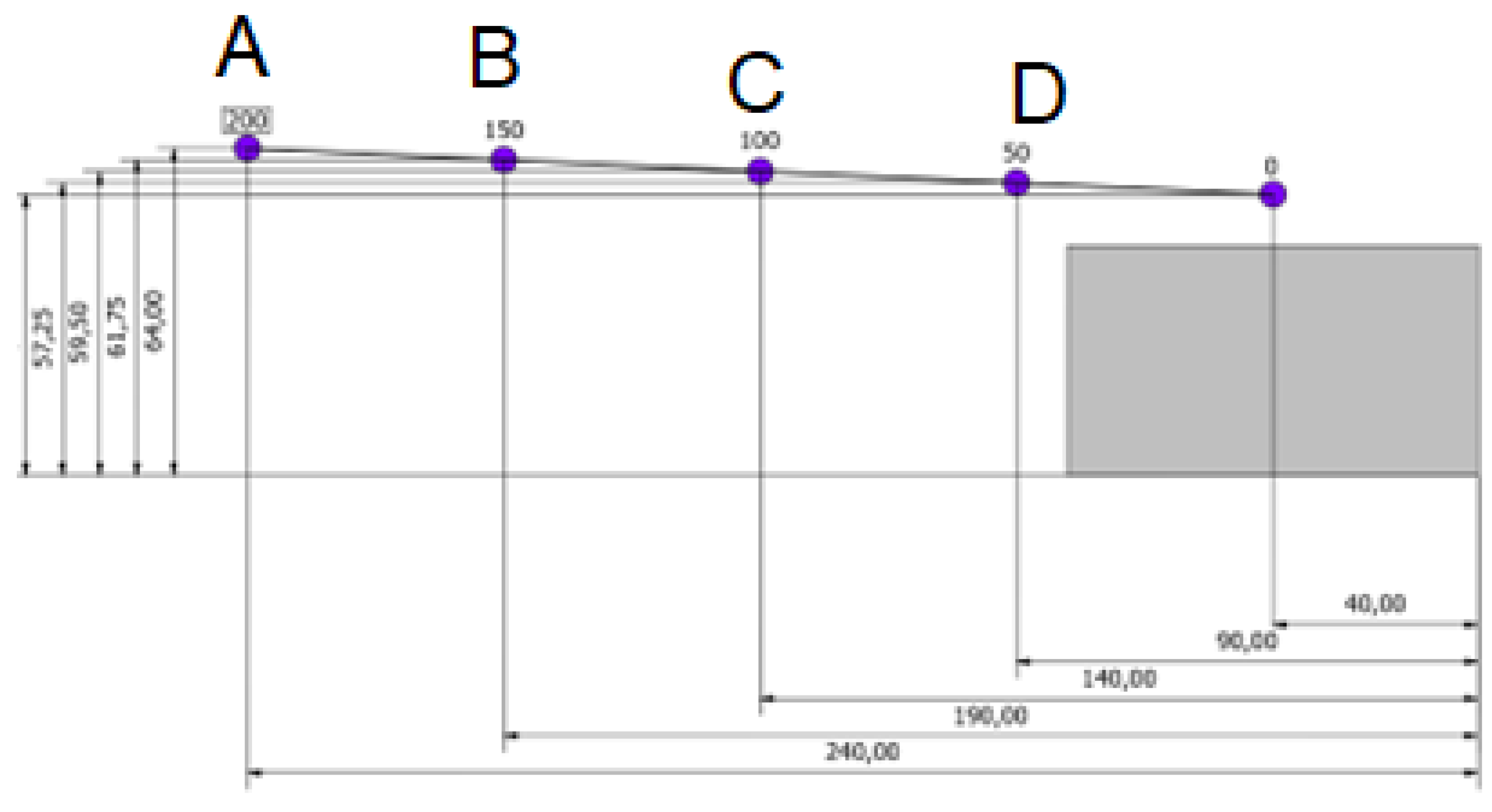
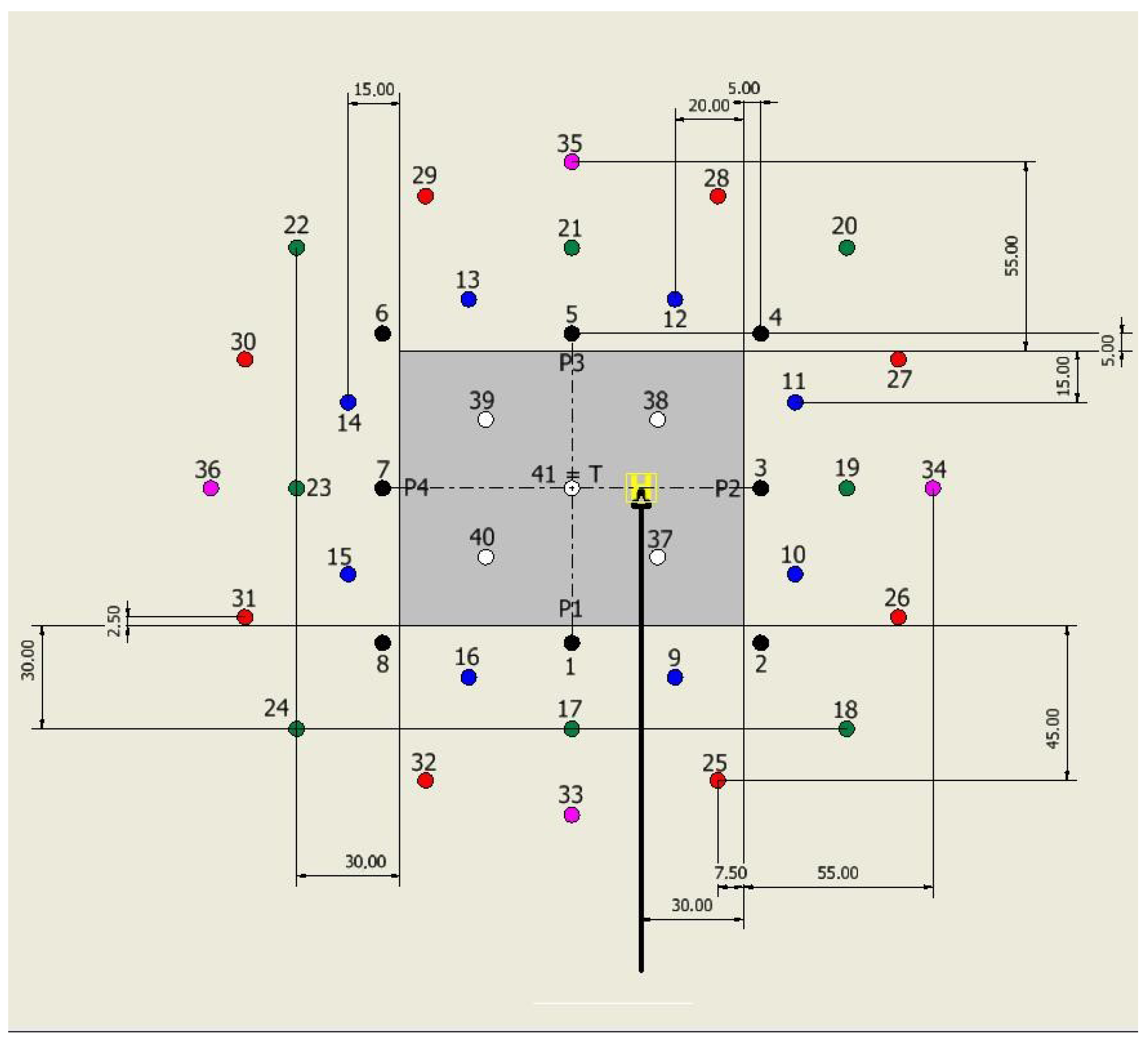
2. Experimental Set Up

Test Rig and Measurements Set Up

The experimental activity was performed at Politecnico di Milano in the 4 m × 4 m × 4 m anechoic chamber of PoliMi Sound and Vibration Laboratory (PSVL) in semi-anechoic configuration, i.e., with a reflecting floor. The goal of the test campaign was to measure the acoustic footprint on the semi-anechoic chamber floor due to the waves emitted by a rotor approaching the reflective roof of a building model. This experiment would enable us to evaluate the noise perception of observers around the building. The layout of the test set up is shown in Figure 1.
The small rotor model used for the experimental activity with diameter D = 0.15 m, see Figure 2, was the same developed for GARTEUR Action Group HC/AG-24 (Helicopter Fuselage Scattering Effects for Exterior/Interior Noise Reduction) [15]. The rotor was driven by an electric DC motor Scorpion HKII-2221-6 (Kv 4400 RPM/V, continuous current 52 A, continuous power 525 W), which through a direct transmission joint rotates the rotor shaft. The rotor is made of blades with a chord of 7 mm. The blades are basically two laminar unfoiled sheets of 1 mm-thick aluminium. The rotor hub has a diameter of 3 cm. Blades do not have a flapping hinge, they are not twisted or bent and they have a fixed incidence of 10 . The rotational speed during the tests was equal to 23,400 rpm, equivalent to a tip Mach number of the blade equal to 0.54 . This value quite resembles the Mach number of full-scale helicopter main rotors. Angular speed regulation and control were managed through Labview software, which operates an acquisition system from National Instruments. Namely, an NI9234 Compact DAQ module (ADC resolution 24 bits, simultaneous sampling mode, accuracy ±50 ppm maximum, data rate range (fs) 1.652 kS/s to 51.2 kS/s) was used, characterised by an integrated anti-aliasing system of filters. The angular speed can be adjusted by means of an electrical throttle, which allows us to change the power delivered to the rotor, while the voltage supply was guaranteed by a 24 V generator. Management and control of the motor operating regime were realised by a Multiplex ROXXY BL-Control 9120-12 Opto control unit, commonly used in hobby-grade model aircraft. The rotor rpm was measured using a Hall effect sensor equipped with a magnet.
The building model (courtesy of DLR) was the same used for GARTEUR Action Group HC/AG-22 (Forces on Obstacles in Rotor Wake) [16] and consists of a 0.45 m high parallelepiped aluminium alloy box with a 1 m × 0.8 m base, see Figure 1. The use of an aluminium box, totally acoustic reflective, was dictated by the fact that this choice allows us to observe wave reflections with nearly no absorption, making it simpler to analyse the ideal interaction effects on the acoustic emission of the rotor. Indeed, the selected box could not simulate the real façade of a building, which could be made from different materials, some of them even porous, but the main goal of the activity is to reproduce a simple but realistic scenario that could provide robust experimental data for numerical solver validation. With this aim, the reproduced scenario only had a single source, i.e., reproducing a main helicopter rotor and a single building model, representative of a reflective surface. Considering both the rotor and building dimensions, a scale factor of λ = 1 / 100 was assumed for the test case with respect to a real urban environment, where a medium-weight full scale helicopter, such as the Airbus H175, equipped with a rotor diameter of almost 15 m is approaching the 80 m × 100 m roof of a 45 m high building. In particular, the full-scale dimensions of the selected building model resemble the real dimensions considered for the construction of an elevated helipad in urban areas. The definition of the scale factor was carefully considered in order to scale the measured frequency for the A-Weighting of noise [17]. Indeed, considering that the maximum frequency correctly detected by the microphone used in these experiments was 20 kHz, if the 1 / 100 scale factor is applied, the maximum frequency appreciable corresponds to 200 Hz in a real urban scenario. Thus, considering that the upper limit of human hearing is about 20 kHz (typically around 17 kHz in adults), there was in principle a large part of noise not reproduced in the experiment. Nevertheless, it must be considered that in the final phase of the approach to the deck, most of the noise produced by the main rotor of the helicopter can be reasonably expected to be in the band reproduced by the experiment. Moreover, the fact that a small-scale experiment corresponds to very low frequencies at full scale cannot be considered a serious drawback if considering that the main goal of this study is producing a database for the validation of prediction tools. Indeed, once validated on the database, numerical solvers could be extended to full-scale configurations. The tail rotor noise characterised by higher frequencies was clearly outside the purpose of this single rotor experiment.
During the tests, the rotor model was positioned at five different points along an approaching path by means of two orthogonal motorised sliding guides. The helicopter descent path reproduced during the tests is shown in Figure 3, where the furthest point of the rotor (A) was positioned at a distance of 2 m before the landing point on the building rooftop, corresponding to 200 m at full scale.
The noise transmitted at soil was measured by means of a flat microphone sequentially located at different positions on the floor for each rotor position. The selected instrument was a model 4949 surface microphone produced by Bruel & Kjaer (frequency = 5 Hz–20 kHz, dynamic range = 30–140 dB, uncertainty = 2 σ = 0.2 dB). Each measurement was performed with an observation time of T s = 10 s at an acquisition frequency of f s = 51.2 kHz. With this data rate, system filtering guaranteed that the band of interest was not affected by aliasing and with negligible attenuation. Due to the low speeds that characterise the helicopter approaching phase, noise analyses performed at fixed rotor positions can be considered sufficiently adequate to describe the phenomenon. Figure 4 shows the observer pattern chosen for microphone measurements around the building model. Their distribution was decided in order to guarantee enough resolution around the building and to analyse different effects caused by interactions between sound waves and building walls. The nearest observers were placed at a distance of 5 cm from the building model, while the furthest were positioned at a distance of 50 cm, i.e., 50 m at full scale.

3. Results and Discussion

The tests allowed us to design a map of the noise at ground level in terms of the Sound Pressure Level (SPL) and to provide a comparison between noise spectra obtained at different ground locations. Constant monitoring of environmental conditions and rotor use states was performed during the tests to ensure a high degree of homogeneity and provide an accurate comparison of the data collected during different trials. Table 1 reports the average and standard deviation values of absolute pressure, temperature and relative humidity recorded in the test chamber during the measurements. In particular, standard deviation values clearly show no remarkable variations in environmental conditions during the tests, as they remained almost constant throughout the campaign.
The repeatability of measurements was checked at a specific microphone location far away from building, the rotor and the semi-anechoic chamber walls. Figure 5 shows a comparison between two spectra collected at the same reference position. This observer, number 48, was placed 2 m away from the frontal wall and rotor sides and 2 m away from the rotor, such that neither interaction with the building nor direct exposure to the rotor wake could affect its recordings. No remarkable difference between the average broadband noise levels and the position of rotor harmonics is appreciable, thus showing a high level or the repeatability of the microphone measurements.
Spectra were obtained by post-processing using a moving mean process over smaller time intervals of T w = 1 s. This process enabled us to reduce random noise that could affect data. A typical spectrum of a signal recorded during the test campaign can be seen in Figure 6, where mainly three components of noise are present as described in the following.
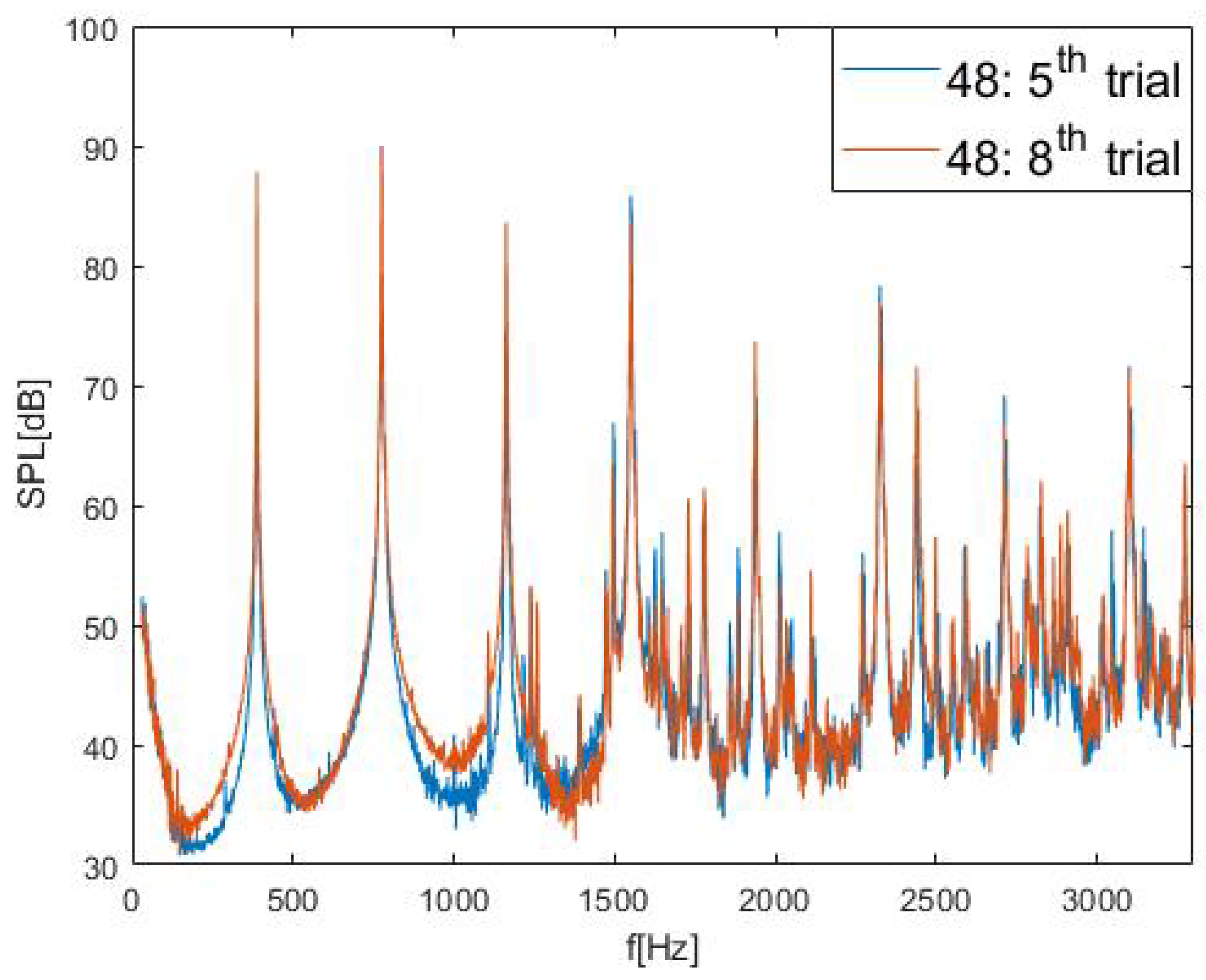
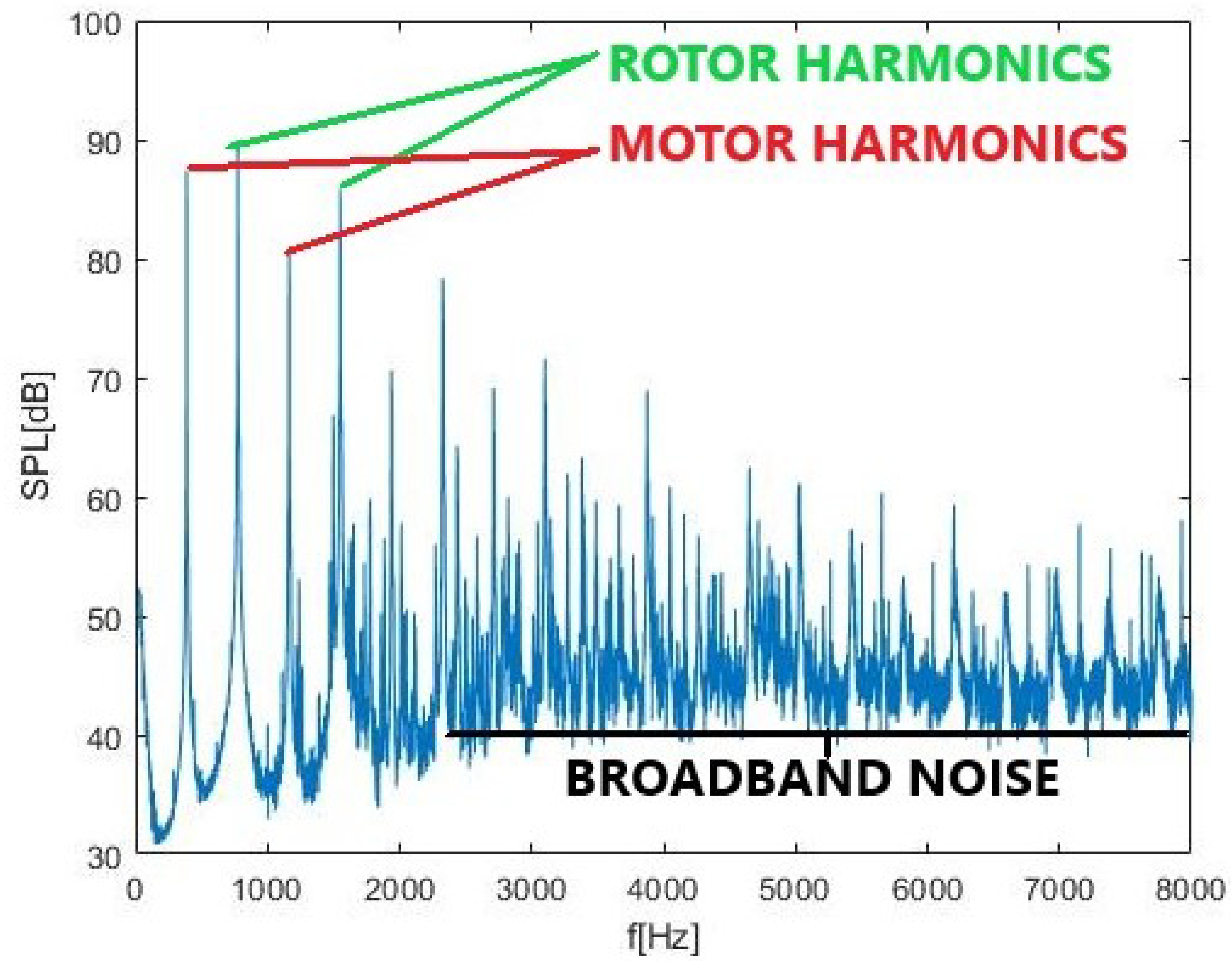
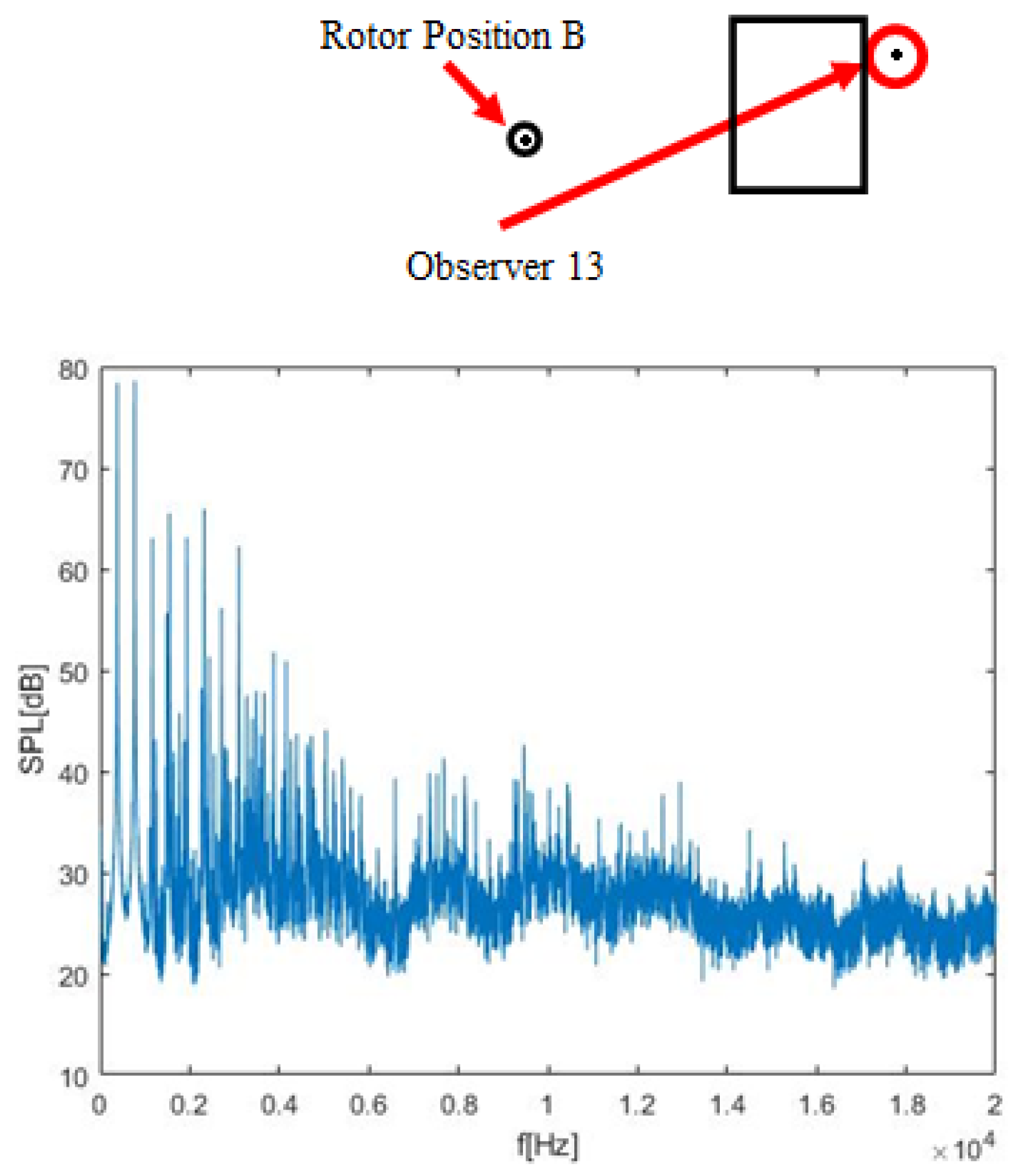
  • Loading Noise: Produced by the pressure variation caused by rotor blade motion and related to lift and drag forces, i.e., a tonal component that is represented by even rotor harmonics 2 n Ω (indicated as “rotor harmonics” in the figure). This noise component can be in a certain extent involved also in odd harmonics ( 2 n + 1 ) Ω , including the fundamental one-per-rev due to possible small asymmetries in rotor blade manufacturing. As can be seen in Figure 6, the first even harmonic 2 Ω presents the highest peak value;
  • Thickness Noise: Due to the air displacement produced by the blade motion. As for the loading noise, it is basically a tonal noise, mainly on the even harmonics;
  • Vibration noise: involved in both odd harmonics (indicated as “motor harmonics” in the figure) and even harmonics and related to the vibrations caused by aerodynamic load and motor operation;
  • Broadband Noise: mainly produced by the turbulence of the generated wake.
The use of a true rotor as source, instead of a small-size electroacoustic device, could introduce undesired tones at odd multiples of the rotational frequency, attributable to the electric motor or to possible asymmetries of the blade geometry that are not part of the aerodynamic rotor noise of interest. Nevertheless, as the main goal of the activity is to build a database suitable for numerical solver validation, the odd tones could be filtered out in post-processing to obtain reliable comparisons with simulations.

Result Analysis

This results discussion is aimed at the showing human-perceived sound as the helicopter is approaching. Thus, the measured SPL maps were drawn on the chamber floor by considering signal spectra scaled to real frequencies using a factor of λ = 1 / 100 . This procedure enabled us to show map results for real buildings and helicopter dimensions. Indeed, as the rotor model tip Mach number can be considered similar to the real helicopter one, the sound frequencies were reported at full scale by simply dividing the measured ones by 100. Then, spectra were A-Weighted at each real frequency in order to obtain sound levels according to the dynamic response of the human ear [17]. The total perceived sound was computed by summing the average amplitudes in each third octave. Since the human ear is much more sensitive to high frequencies with respect to lower ones, the rotor harmonic contribution is weak, since the loudest contributions are found at low frequencies. The sound maps measured with the rotor, respectively, at positions A, B, C and D are presented in Figure 7 and are rotated by 90 with respect to the sketch in Figure 4, so that the rotor model is approaching the building from the left side of the map. The sound map with the rotor positioned at D was not completed, as the last measurement points of the survey could not be performed due to fatigue damage to the system provided by the high rotation regime and the huge number of test runs included in the campaign. Nevertheless, the global behaviour of the noise at the floor is also appreciable for this test condition.
The measured maps clearly show the growth of noise in the front region of the building as the rotor approaches, reaching a perceived level of about 60 dBA when the rotor is at position D, i.e., 50 m at full scale before the landing point. At the same time, the shielding effect of the building is apparent. Indeed, considering again the condition with the rotor at position D, the noise perceived around most of the rear region of the building remains around 25 dBA. These sound maps allow us to obtain very clear and synthetic information about the noise level around the building. Nevertheless, in order to obtain better insights in the physics of the phenomena, pressure signal spectra have to be analysed.
The pressure signal spectra presented in the following were not A-weighted in order to retain all the possible physical information, and the frequencies reported on the abscissa axis are the measured frequencies, not reported to full scale, as was done to calculate sound maps. Figure 8 presents the spectra of the noise perceived by two different observers, Observer 1 (quite close the front face of the building) and Observer 33, with the rotor at 2 m, i.e., 200 m at full scale, away from the landing point. Looking first at the signal spectrum for Observer 1 positioned at 5 cm from the wall, high levels of broadband noise (around 40∼50 dB) and high SPL peak values, reaching almost 100 dB, can be observed. Spectral analysis shows that in this area, the main phenomenon caused by interaction of sound waves with the building is reflection.
This effect can be observed in the Observer 1 spectrum by the pattern created by the alternation of constructive and destructive interference, caused by phase displacement between direct and reflected sound waves. Indeed, constructive interference is found at multiples of the frequency related to the difference in covered distance by the direct and reflected waves δ . On the other hand, phase opposition interference occurs at odd multiples of the frequency related to half of δ . In this case, δ = 0.196 m, and considering the sound speed characterising this trial, i.e., c = 342.6 m/s, the frequency related to the first phase opposition is f 1.7 kHz, which matches that shown in the figure.
Looking then at the second spectrum for Observer 33, i.e., 60 m from the wall at full scale, the peaks and valleys due to interferences are still visible but they are much closer each to other. This is due to the larger difference in distance covered by direct and reflected waves. This fact causes a decrease in frequency related to the first interaction and an increase in the rate of wave frequency interference. Together with a change in the pattern rate, a decrease in the strength of this phenomenon is found as the observers become further away from the building’s front wall. It is possible to notice that the difference in amplitude between constructive and destructive interference changes from about 20 dB for Observer 1 to about 10 dB for Observer 33. Thus, the effect of reflection at the same distance of the height of the building model was close to negligible.
Another physical effect which characterises observers placed in the front area of the building is the exposure to the rotor wake. For example, by focusing on the frequency band at 3.5 kHz, an effect on broadband noise can be observed in the zoomed spectra presented in Figure 9 and measured for the same Observer 33 with the helicopter in two different positions (A and C). As expected, the SPL spectrum level is higher when the rotor is just over the observer, i.e., the rotor is in position C, with respect to when the rotor is further away, i.e., the rotor is in position A. The effect is particularly apparent in the region of the presented spectra below 1500 Hz, which, at full scale, corresponds to 15 Hz, and thus is below the audible range. Nevertheless, this low-frequency broadband part of the spectrum is contaminated by pseudo sound pressure fluctuations [18,19] related to the turbulent impinging rotor wake. On the other hand, for the frequency band over 1500 Hz, the broadband noise level is also considerably higher when the rotor is over the observer, i.e., around 55∼60 dB, while it is about 50 dB when the rotor is further away.
Measurements in the rear region of the building highlighted two other physical phenomena that influence observers in this area, i.e., shielding and diffraction. The former is provided by the presence of the building that causes a general decrease in broadband noise sound levels, as can be seen from the spectrum shown in Figure 10 measured for Observer 13 with the rotor in position B. This results in the average values reducing to about 20∼35 dB, which is far less than the ones found in observers analysis in front of the building. Rotor harmonics are also affected by shielding, and their peak values do not reach 90 dB. The effect of shielding is particularly intense at high frequencies, see Figure 10, where the broadband noise suffers from a constant decrease with increasing frequency. Indeed, while sound waves with greater wavelengths, i.e., two or three times the height of the building, can pass the obstacle and reach the observer, high frequency waves are more shielded by the building edge due to the presence of an obstacle.
The second phenomenon is diffraction, which exhibits typical behaviour caused by wave interference. This effect is caused by the interaction between the building edge and sound waves produced by the helicopter. When waves arrive at the building rear edge, each point of the edge turns into a new orthotropic sound source. Thus, an observer hears sound waves coming from different points, which have covered different distances and are then affected by phase displacement. This difference in phase causes different interferences, which are clearly visible in the figure. Similarly to what was observed due to reflection, a pattern of destructive and constructive interactions is present.
Generally, for the sake of consistency, results from the experimental database were selected to be presented in this paper with the aim of showing the main acoustic phenomena related to the investigated problem, i.e., reflection, diffraction and shielding. Nevertheless, the complete experimental database is completely public and available for further post-processing on request to the authors, in order to be valuable for a thorough validation of numerical solvers.

4. Conclusions

An experimental campaign was performed in the semi-anechoic test chamber of Politecnico di Milano to investigate the noise effects related to the acoustic emission of a rotor approaching a reflective helipad on the roof of a building. The adopted test rig was composed of a small two-blade rotor and a square building model, reproducing an urban scenario. The rotor model was positioned at different points along the descending path and, for each of them, the noise at several points on the floor around the building model was measured by means of a flat microphone.
Thanks to this relatively simple setup, the main phenomena related to the noise transmitted by the helicopter rotor to the soil during this approach manoeuvre have been highlighted, producing a general picture of the problem. Indeed, the obtained maps of sound pressure levels provide a synthetic description of the noise distribution for different phases of the approaching manoeuvre. Furthermore, an analysis of the sound pressure spectra at some specific points fundamentally contribute to a better physical insight into the involved phenomena. In particular, it was possible to identify the effects of reflection on the front facade of the building, as well as the effects of diffraction on the back edge that partially reduce the shielding effect.
In conclusion, the results presented in this study provide a global perspective of the involved phenomena and help in gaining a detailed understanding of people’s perception of noise close to a building when a helicopter is approaching an elevated urban helipad. Moreover, the experimental database, obtained over a free geometry, can be considered a useful tool for the validation of aeroacoustic solvers with different levels of fidelity. Indeed, the obtained database provides publicly available comprehensive quantitative information for acoustic code validation.
Concerning future developments of the present work, for helicopters operating in urban environments, the noise impact on facades is also important; thus, the present set up could be easily updated by also installing instruments in the building model walls. Moreover, a further development of this research activity could be a study of the noise footprint of the approach of a multi-rotor system in an urban scenario.

Author Contributions

Conceptualisation, G.G., S.R., M.R. and A.Z.; methodology, G.G., S.R., M.R. and A.Z.; investigation, G.G., S.R., M.R. and A.Z.; resources, G.G. and A.Z.; data curation, G.G., S.R., M.R. and A.Z.; writing—original draft preparation, G.G., S.R., M.R. and A.Z.; writing—review and editing, G.G., S.R., M.R. and A.Z.; visualisation, G.G., S.R., M.R. and A.Z.; supervision, G.G. and A.Z.; project administration, G.G. and A.Z.; funding acquisition, G.G. and A.Z. All authors have read and agreed to the published version of the manuscript.

Funding

This research received no external funding.

Conflicts of Interest

The authors declare no conflict of interest.

Abbreviations

The following abbreviations are used in this manuscript:
AAMAdvanced Air Mobility
csound speed
eVTOLelectrical Vertical Take-Off and Landing
ffrequency
f s acquisition frequency
nnumber of harmonics
rpmround per minute
SPLSound Pressure Level
T s observation time
T w time interval
δ covered distance by direct and reflected waves
λ scale factor
σ standard deviation
Ω angular speed

References

  1. Lusiak, T.; Ziubiński, A.; Szumanski, K. Interference between helicopter and its surroundings, experimental and numerical analysis. Task Q. 2009, 13, 379–392. [Google Scholar]
  2. Vouros, S.; Goulos, I.; Pachidis, V. Integrated methodology for the prediction of helicopter rotor noise at mission level. Aerosp. Sci. Technol. 2019, 89, 136–149. [Google Scholar] [CrossRef]
  3. Schomer, P.; Hoover, B.D.; Wagner, L.R. Human response to helicopter noise: A test of a-weighting. In DOD Noise Source Human Response Characterization; Technical Report, N91-13; US Army Corps of Engineers, Construction Engineering Research Laboratory: Champaign, IL, USA, 1991. [Google Scholar]
  4. Ahuja, K.; Funk, R.; Hsu, J.; Heighs, M.; Charles, S. Operation Helistar—Effects of Buildings on Helicopter Noise; DOT/FAA/ND 97-13 5, FAA; U.S. Department of Transportation: Washington, DC, USA, 1997. [Google Scholar]
  5. Hilton, D.A.; Pegg, R.J. The Noise Environment of a School Classroom Due to the Operation of Utility Helicopters; Nasa tm x-71957, NASA Technical Memorandum; NASA: Washington, DC, USA, 1974. [Google Scholar]
  6. Doolan, C.J.; Leclercq, D. An anechoic wind tunnel for the investigation of the main rotor/tail-rotor blade vortex interaction. In Proceedings of the 6th Australian Vertiflite Conference on Helicopter Technology, Melbourne, Australia, 20–22 March 2007. [Google Scholar]
  7. Feight, J.A.; Jacob, J.D.; Gaeta, R.J. Acoustic characterization of a multi-rotor uas as a first step towards noise reduction. In Proceedings of the AIAA SciTech Forum, 55th AIAA Aerospace Sciences Meeting, Grapevine, TX, USA, 9–13 January 2017. [Google Scholar]
  8. Zawodny, N.S.; Boyd, D.J. Investigation of rotorairframe interaction noise associated with small-scale rotary-wing unmanned aircraft systems. In Proceedings of the AHS 73rd Annual Forum, Fort Worth, TX, USA, 9–11 May 2017. [Google Scholar]
  9. Yang, Y.; Liu, Y.; Hu, H.; Liu, X.; Wang, Y.; Arcondoulis, E.J.; Li, Z. Experimental study on noise reduction of a wavy multi-copter rotor. Appl. Acoust. 2020, 165, 107311. [Google Scholar] [CrossRef]
  10. Yin, J.; Rossignol, K.S.; Barbarino, M.; Bianco, D.; Testa, C.; Brouwer, H.; Janssen, S.R.; Reboul, G.; Vigevano, L.; Bernardini, G.; et al. GARTEUR activities on acoustical methods and experiments for studying on acoustic scattering. CEAS Aeronaut. J. 2019, 10, 531–551. [Google Scholar] [CrossRef]
  11. Thai, A.D.; De Paola, E.; Di Marco, A.; Stoica, L.G.; Camussi, R.; Tron, R.; Grace, S.M. Experimental and Computational Aeroacoustic Investigation of Small Rotor Interactions in Hover. Appl. Sci. 2021, 11, 10016. [Google Scholar] [CrossRef]
  12. Jia, Z.; Lee, S. Acoustic Analysis of a Quadrotor eVTOL Design via High-Fidelity Simulations. In Proceedings of the 25th AIAA/CEAS Aeroacoustics Conference, Delft, The Netherlands, 20–23 May 2019. [Google Scholar]
  13. Poggi, C.; Bernardini, G.; Gennaretti, M.; Camussi, R. Scalability of Mach Number Effects on Noise Emitted by Side-by-Side Propellers. Appl. Sci. 2022, 12, 9507. [Google Scholar] [CrossRef]
  14. Yin, J.; Rossignol, K.S.; Rottmann, L.; Schwarz, T. Numerical investigations on small-scale rotor configurations with validation using acoustic wind tunnel data. In Proceedings of the 48th European Rotorcraft Forum, Winterthur, Switzerland, 6–8 September 2022. [Google Scholar]
  15. Yin, J.; Zanotti, A.; Gibertini, G.; Vigevano, L.; Rossignol, K. Design of a Generic Rotor Noise Source for Helicopter Fuselage Scattering Tests. In Proceedings of the 44th European Rotorcraft Forum (ERF 2018), Delft, The Netherlands, 18–21 September 2018; pp. 11–20. [Google Scholar]
  16. Gibertini, G.; Grassi, D.; Parolini, C.; Zagaglia, D.; Zanotti, A. Experimental Investigationon of the Aerodynamic Interaction Between a Helicopter and Ground Obstacles. Proc. Inst. Mech. Eng. Part G J. Aerosp. Eng. 2015, 229, 1395–1406. [Google Scholar] [CrossRef]
  17. Cowan, J. Handbook of Environmental Acoustics; John Wiley and Sons: Hoboken, NJ, USA, 1994. [Google Scholar]
  18. Ffowcs Williams, J.E. Noise source mechanisms. In Modern Methods in Analytical Acoustics, Lecture Notes; Springer: Berlin/Heidelberg, Germany, 1992. [Google Scholar]
  19. Grizzi, S.; Camussi, R. Experimental investigation of the Near-Field Noise generated by a Compressible Round Jet. J. Phys. Conf. Ser. 2011, 318, 092003. [Google Scholar] [CrossRef]
Figure 1. Experimental set up in the PoliMI Sound and Vibration Laboratory (PSVL) semi-anechoic chamber.
Aerospace 10 00701 g001
Figure 2. View of the rotor model used for the tests.
Aerospace 10 00701 g002
Figure 3. Rotor descent trajectory, dimensions in cm.
Aerospace 10 00701 g003
Figure 4. Measurement point distribution on the floor, dimensions in cm. The extra reference position 48 was located 2 m from the building and 2 m from the rotor in position A.
Aerospace 10 00701 g004
Figure 5. Repeatability check of microphone measurements: spectra comparison of signals acquired at the same reference point. Observer 48.
Aerospace 10 00701 g005
Figure 6. Typical spectrum recorded by reference observer 48.
Aerospace 10 00701 g006
Figure 7. Noise maps measured with approaching rotor.
Aerospace 10 00701 g007
Figure 8. Spectra comparison showing reflection phenomenon, with the rotor model at 2 m from landing point.
Aerospace 10 00701 g008
Figure 9. Broadband noise increase due to the contamination by the turbulent wake of the rotor.
Aerospace 10 00701 g009
Figure 10. Spectrum at the rear of the building subject to shielding. Observer 13.
Aerospace 10 00701 g010
Table 1. Environmental conditions measured during the tests.
Mean Value σ
Pressure ( 10 4 Pa)9.91380.0057
Temperature (K)291.930.31
Relative Humidity ( % R H )39.51.2
Disclaimer/Publisher’s Note: The statements, opinions and data contained in all publications are solely those of the individual author(s) and contributor(s) and not of MDPI and/or the editor(s). MDPI and/or the editor(s) disclaim responsibility for any injury to people or property resulting from any ideas, methods, instructions or products referred to in the content.

