1. Introduction
In the pursuit of a more sustainable future, the aviation industry is at the forefront of efforts to reduce its environmental impact and achieve the ambitious goal of zero emissions. Globally, numerous programs and initiatives are underway to address this challenge. In Europe, the seven-year Clean Sky 2 program will end in 2023 while the new Clean Aviation [
1] program started at the beginning of 2023, as a collaborative effort involving industry, research institutions, and government entities, which aims to develop and implement innovative technologies that significantly reduce emissions from aircraft [
2,
3]. Similarly, in the United States, organizations like NASA and the Federal Aviation Administration (FAA) are actively engaged in research and development initiatives to advance environmentally friendly aviation technologies [
4].
These international programs underscore the urgency and significance of reducing the environmental impact of aviation. Indeed, the continuous growth of the aircraft transport market further emphasizes the need for sustainable solutions. As air travel becomes more accessible and global connectivity increases, the demand for air transportation continues to rise [
5], so increasing the demand for air transport and the associated environmental challenges, reinforcing the need for emissions reduction efforts as reported in the Clean Aviation Strategic Research Agenda (SRIA) [
3] and in Flightpath 2050 [
6].
Aircraft are typically the result of a multidisciplinary design compromise involving different disciplines at the same time. Indeed, an improvement of a single discipline could automatically produce a decrease in performance of another one, so the most promising configuration of future aircraft must be obtained by exploiting this multidisciplinary approach from the first phases of the design loop. However, it is easy to identify some general trends in the identification of the most promising technologies. For example, one critical aspect of addressing the environmental impact of aircraft operations is the reduction of structural weight. This is in contrast with the solutions usually adopted for improved aerodynamics, typically based on slender wings with higher aspect ratio and thinner airfoils producing more flexible structures, which are prone to aeroelastic issues, demanding enhanced structural requirements to sustain the loads. By implementing active control systems for load alleviation, the aerospace industry aims to optimize aircraft structures, resulting in reduced weight while maintaining safety and structural integrity [
7,
8,
9]. This weight reduction has a direct correlation with fuel efficiency, as lighter aircraft require less energy to propel and sustain flight. Consequently, active controls play a pivotal role in achieving fuel savings and emissions reduction targets set forth by international programs.
In addition to gust load alleviation, maneuver load alleviation technologies also play a crucial role in reducing structural weight and improving aircraft performances. Maneuvers, such as high-speed turns and aggressive flight maneuvers, impose significant loads on the aircraft structure, which can lead to increased weight and reduced efficiency. Active control systems can actively counteract these maneuver-induced loads, mitigating their impact on the structure and allowing for lighter and more efficient designs [
10,
11]. The implementation of advanced control algorithms and actuators enables active control systems to dynamically adjust the aircraft’s control surfaces and redistribute loads during maneuvers, effectively reducing structural stresses and improving overall performance [
12,
13,
14,
15].
In light of the international programs dedicated to emissions reductions and the increasing demand for air transportation, the integration of active control systems for both gust and maneuver load alleviation becomes increasingly crucial. These systems not only contribute to the weight reduction of aircraft structures but also align with the industry’s sustainability objectives. By reducing structural weight and, consequently, fuel consumption and emissions, active controls play a vital role in achieving the environmental targets set by international programs while accommodating the growing demands of the global aviation market.
This paper aims to provide an overview of a part of the research activity carried out under the Clean Sky 2 AIRGREEN2 project to conceive, design, and test an innovative wingtip device specifically dedicated to gust and maneuver load alleviation technologies. It will explore the entire development roadmap, starting from initial conceptual design, evolving through a series of experimental campaign on scaled models, and finally analyzing the qualification full-scale static test, until the delivery of the item in view of future flight test campaigns.
2. The Clean Sky 2 AIRGREEN2 Project
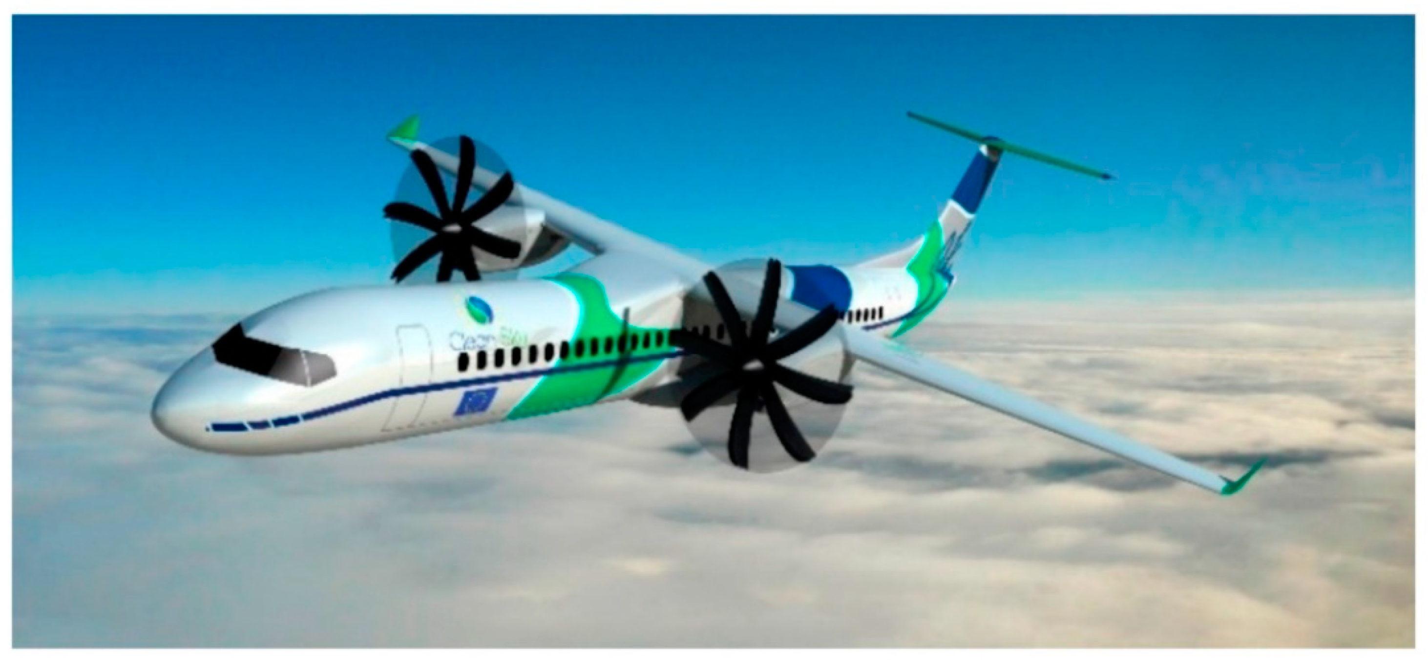
The Clean Sky 2 program’s (2015–2022) goal was to diminish the pollution footprint of the new generation regional aircraft, consolidating the developed technologies for short-term industrial application. The WP2.1 (Electric Adaptive Wing) of Clean Sky 2 Project Regional-IADP was co-led by Leonardo S.p.A and ADS Spain acting as topic managers. Under this umbrella, the AIRGREEN2 project, coordinated by the Italian Aerospace Research Centre (CIRA) and including universities, SMEs, and research centers, focused on the development of active and morphing technologies to be installed on a new regional aircraft that carries 90 passengers, equipped with two conventional wing-mounted turbo propellers and named Turbo-Prop 90 Passengers (TP90), as represented in
Figure 1. The reference aircraft is a concept developed by Leonardo S.p.A.
Among the large portfolio of investigated technologies, the most relevant concerning the wing are the following:
The implementation of a morphing mechanism on the main flap to improve the high-lift performances [
16].
The replacement of conventional leading edge high-lift devices with a morphing droop-nose that improves the aerodynamic performances during take-off, climb, and landing phases. It is used in combination with the morphing flap and, most importantly, since it is smooth and gapless it is able to facilitate the implementation of natural laminar flow [
17,
18,
19,
20,
21,
22].
A winglet with two finger-like control surfaces that is used in the climb phase and to control the lift distribution to alleviate the maneuver loads [
23].
Implementation of maneuver load alleviation (MLA) and gust load alleviation (GLA) technologies to reduce the structural weight using primary and newly developed control surfaces with a general target of reducing the wing root bending moment by at least 20%.
Development of a wingtip device, named Innovative WingTip (IWT), equipped with a conventional movable surface used to actively control the dynamic loads due to atmospheric turbulence and maneuvers.
For all the items, it was required to improve the technology readiness level (TRL) up to 6, which corresponds to the testing in a relevant environment. In particular, the wingtip and winglet devices are expected to be tested in flight by the end of the program, i.e., in December 2023, while the other morphing devices were already ground tested on large-scale demonstrators to assess their functionality.
The development of IWT is focused on the new generation regional aircraft TP90, used throughout AIRGREEN2 as a common benchmark. However, since this aircraft is still under design the flight test for the wingtip’s qualification will be performed on the C27J Spartan aircraft, which has a similar configuration (high wing and turbo propeller) to the TP90 and is made available by Leonardo S.p.A. For this reason, although the whole aero-servo-elastic development of the item is oriented to the TP90, the structural layout and ground demonstrator are steered towards the C27J. This does not undermine the validity of the approach followed during the development process, since the final aim of the project is to perform a qualification and validation assessment of the alleviation capability achievable with the IWT.
In this framework, this paper focuses on the development of the only wingtip, showing the multidisciplinarity of the design of this item. The following sections cover all the design disciplines during the development, from the conceptual design to the structural qualification test performed on the ground demonstrator, passing through the structural design and analysis, the active control law verification, the actuation system design, and the wind tunnel testing of scaled models.
3. The Active Wingtip Concept
Most of the applications of active controllers for gust and maneuver load alleviation are based on the use of the standard control surfaces of the aircraft, usually ailerons and elevators. However, there are some cases where the controllers have the possibility to use dedicated control surfaces. Historically, one particular situation where additional control surfaces were used occurred when fuselage modes needed to be controlled, as in the case of the LAMS system [
24] or the fuselage mode suppression system mounted on the B-1 Lancer aircraft [
25]. There are also examples of aircraft equipped with control surfaces dedicated to gust alleviation, like the GLAS surface mounted on the B-23 and the direct lift control (DLC) flaps mounted on the ATTAS aircraft [
26]. Dedicated control surfaces were also studied in wind tunnel models: in [
27], a trailing edge surface was used for load alleviation but was not very effective, different configurations of wingtip surfaces were applied to the EuRAM model [
28], and a series of numerical studies [
29,
30] provide an example of the good performances of the devices.
A particular configuration that can be used for providing an aircraft with additional control surfaces for load alleviation consists in designing a wingtip equipped with an actively controlled surface. Increasing the span of an aircraft has the advantage of improving its aerodynamic efficiency, but usually at the expense of an increase in loads. The increase in loads can be avoided by designing the chord and twist distribution of the wing in order to obtain a desired value of wing root bending moment [
31,
32] but in many applications the wingtip extension needs to be applied as a retrofit for an existing aircraft and, in that case, it is not possible to redesign the wing to limit the load increase. For this configuration, Withcomb showed that winglets are more suitable than wingtips for increasing the aerodynamic efficiency [
33]. An optimization study performed in [
34], however, further analyzed the differences between winglets and wingtips and showed how the optimal solution can depend on the maximum lift coefficient required, with the winglet performing better when maneuvering conditions with high lift coefficients are included in the analysis.
One way to overcome the limitations in the performances of the wing’s tip extensions is to provide some active or passive alleviation capability, for example, in [
35] a wingtip extension for an A300 aircraft was designed, using aeroelastic tailoring for passive maneuver load alleviation and coupling it with an active gust load alleviation system. Other examples of wingtips designed for passive load alleviation can be found in [
36] where two concepts of a rigid wingtip with elastic attachment and an optimized composite wingtip were analyzed.
In the framework of the AIRGREEN2 project, POLIMI developed an innovative wingtip concept based on the extension of the wing which is equipped with a movable control surface designed for the TP90 aircraft of
Figure 1. The selected configuration follows the same structure as the one presented in [
37] consisting in a wing’s tip extension equipped with a trailing edge control surface, as sketched in
Figure 2.
Placing a control surface at the wing’s tip has some disadvantages from the point of view of the load alleviation; one limitation is due to the small surface available, both due to the wing taper and to limitations in the increase in span. The chord and span of the wingtip need indeed to be limited, also taking into account limitations not directly related to the gust load alleviation problem, for example, the cost of airport gates that depends on the aircraft span.
A second limitation related to the wingtip configuration is the small distance from the added control surface to the elastic axis of the wing, while this distance could be exploited to increase the effectiveness of the controller. However, the reference aircraft considered here has a very high torsional stiffness of the wing, which can reduce the potential benefits coming from the use of an aerodynamic surface placed far from the elastic axis. A third limitation is related to the position of the control surface close to the wing’s tip, where there is a strong effect of the wingtip vortices, and the aerodynamic loads are the lowest in the wing. On the other hand, the hinge moments required for the actuation will also be lower, partially compensating for this disadvantage.
In addition to the above-mentioned limitations related to the use of an active wingtip for load alleviation, there are also advantages related to this configuration: the first one is the possibility to combine the load alleviation capability with an increase in aerodynamic efficiency coming from the span extension. From a different perspective, the increase in efficiency could be seen as the main goal of the wingtip design, with the gust load alleviation system used to compensate for the increase in wing loads coming from the extension, as actually carried out with the L-1011 aircraft [
38] and in the theoretical studies on the A300 aircraft.
The main purpose of the active IWT is to alleviate dynamic gust loads (GLA functionality); this is obtained through the implementation of a feedback control law based on the measurement of accelerations on several points on the aircraft structure.
The active wingtip can also be used for maneuver loads alleviation (MLA functionality), that is to modify the lift distribution on the aircraft during maneuvers in order to reduce structural loads [
39]. Maneuver load alleviation controllers can be designed when the number of available control surfaces is higher than the minimum required for the equilibrium of the aircraft, and two different approaches can be followed for its design. The first approach consists in the definition of a dynamic controller for maneuver load alleviation [
40,
41] while the second one is based on a static analysis of the maneuver conditions. In this way, an optimal distribution of surface deflections is defined for each condition, leading to the formulation of pre-selected gains relating the measurements of the aircraft rigid state with the control surface deflection command.
The IWT concept developed in the AIRGREEN2 project involves the development of a device that can be installed at the wing’s tip, either independently or in conjunction with conventional control surfaces, to perform gust load alleviation (GLA) and maneuver load alleviation (MLA). Placing this device at the wing’s tip is advantageous due to the increased leverage it provides, resulting in a greater impact on the wing root bending moment (WRBM), which is a critical factor influencing wing structural design. By incorporating a control surface specifically designed for load control, the overall load envelope can be reduced. This brings several benefits, such as the potential to enhance the fatigue life of the wing, improving the whole life cycle operability of the aircraft and reducing the load envelope.
The alleviation of the dynamic loads, achieved with active control technologies and devices, allows us to consider reduced load envelopes in the structural design, which directly translates to savings in structural mass. As can be seen by Breguet’s range equation, a lighter structure directly influences the aircraft’s range, enabling it to cover greater distances while consuming less fuel on a given route.
A secondary benefit of implementing a wingtip device for load alleviation is the extension of the wing’s aspect ratio, resulting in reduced induced drag and improved aerodynamic efficiency.
Numerous studies, such as [
34], have focused on the wing’s tip design and its influence on overall wing performance. However, these investigations primarily emphasized the aerodynamic advantages associated with tip devices. This work, on the other hand, is specifically oriented towards designing a wingtip device with the primary objective of active load reduction. Consequently, it is insufficient to solely consider the physical design of the device; equal attention must be given to the design of the active components in conjunction with the aerostructural aspects.
In this context, the term “active” refers to the design of the complete servo system utilized for load alleviation. This system comprises sensors, actuators, and control laws that work together to mitigate the loads experienced by the wing. From this brief introduction, the multidisciplinary nature of this project becomes evident, necessitating a holistic and concurrent approach that encompasses various disciplines such as aero-servo-elasticity, structures, aerodynamics, sensing and control, actuation, and more. Such an approach is essential to fully model and understand the interdisciplinary impact of the active wingtip design.
4. Innovative Wingtip Design
This section is divided into subsections, each one representing a single discipline, where the relevant aspects considered are described in detail.
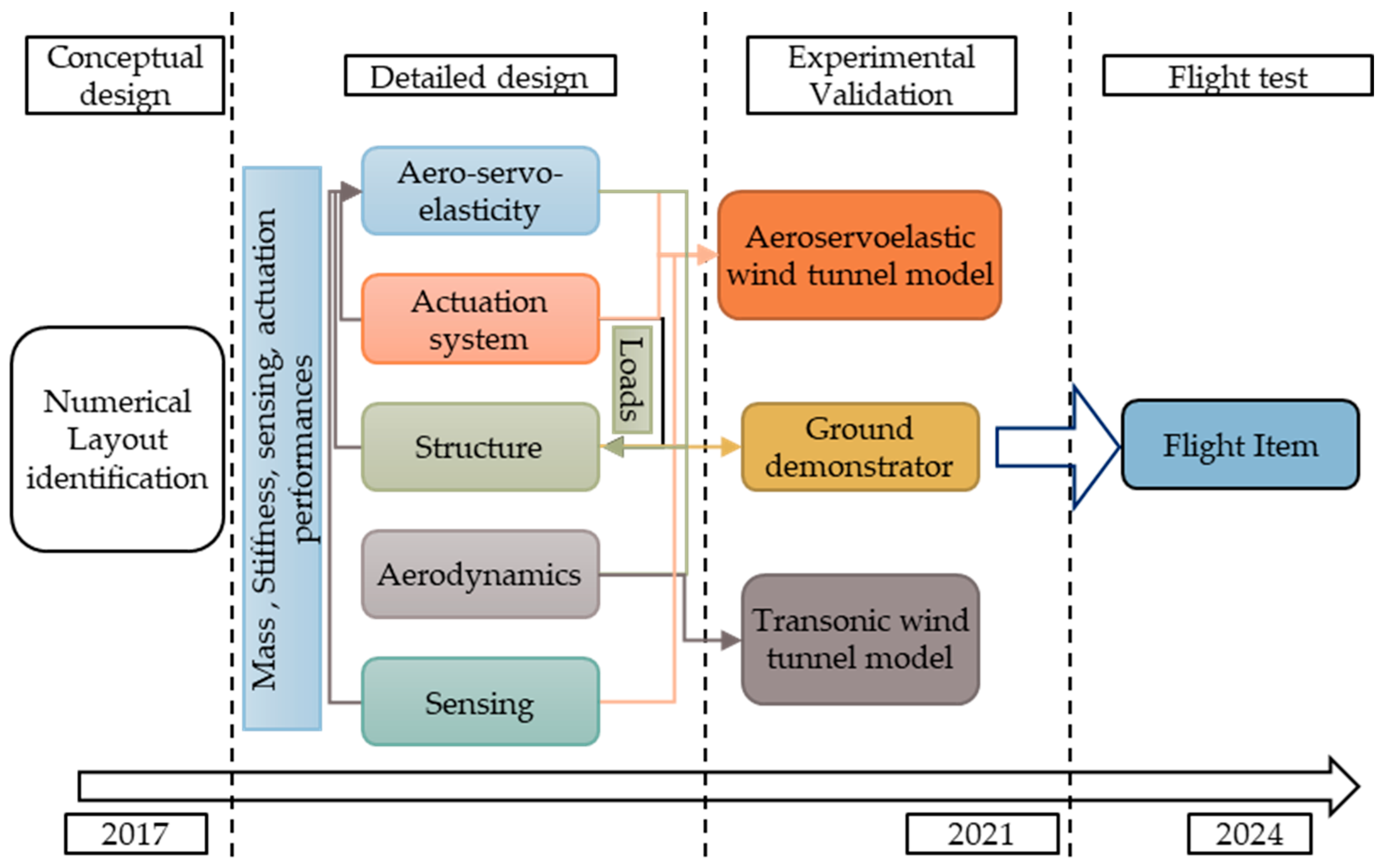
In general, the design development plan followed the roadmap reported in
Figure 3.
4.1. Conceptual Design
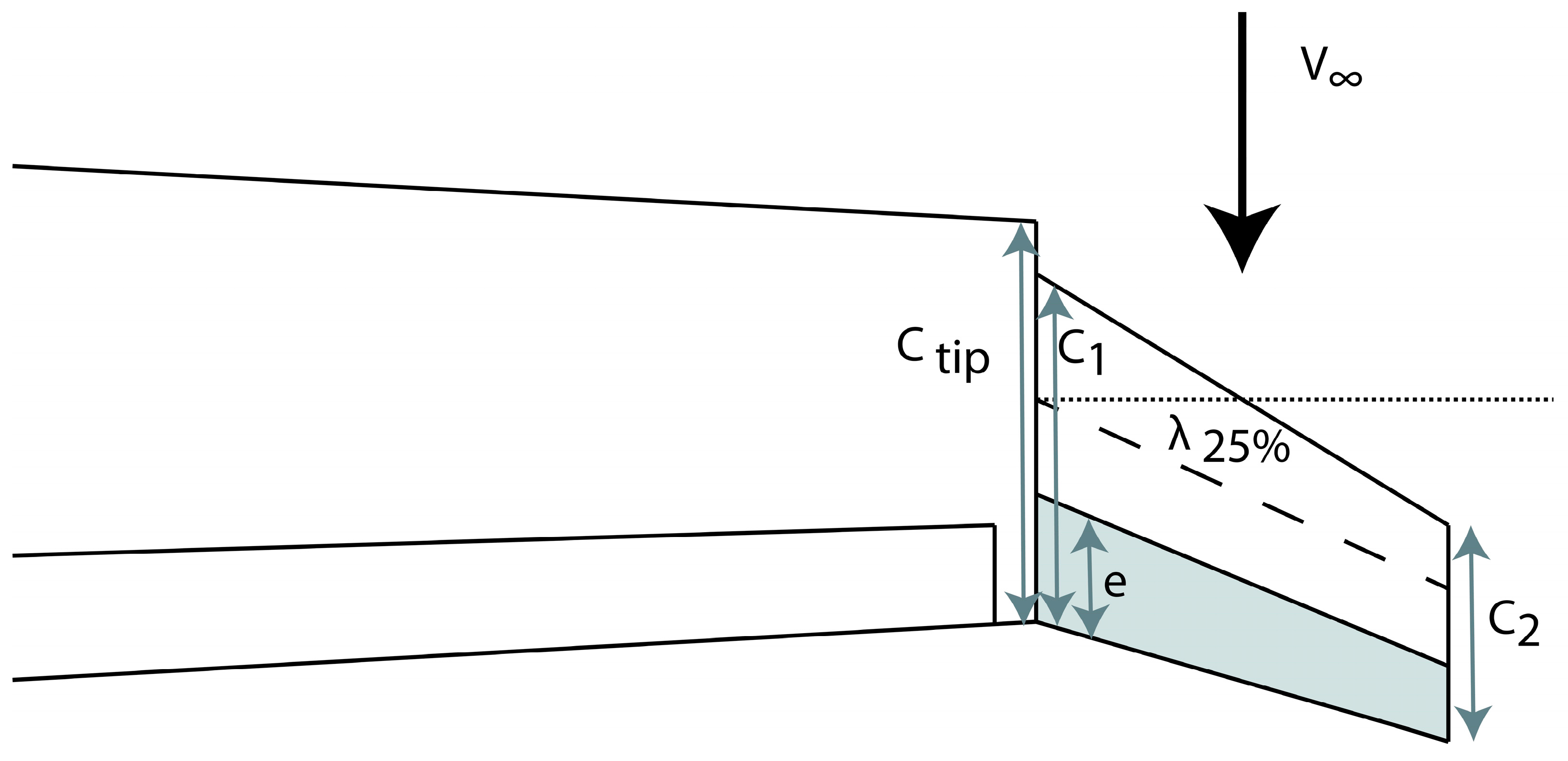
The conceptual design was carried out by POLIMI within the AIRGREEN2 consortium and consisted in the identification of the optimal layout of the wingtip device, the complete study is fully described in [
42]; it involved a parametric study of the main geometrical properties of the wingtip as illustrated in
Figure 4.
The wingtip was included as an extra aerodynamic surface in an existing aeroelastic stick model of the reference TP90 aircraft, where the structure is represented by a FEM stick model and the aerodynamics by a vortex and/or doublet lattice method (VLM/DLM) depending on the steady or unsteady analyses under investigation. The model is shown in
Figure 5. It was realized in a standard Nastran’s format and it was analyzed using NeoCASS [
43,
44,
45,
46], the general aeroelastic framework developed by POLIMI, which allows the performance of aeroelastic simulations (trim, flutter, dynamic response, state-space modeling) and thanks to its open-source nature allows the recovery of much information from the solution without using a dedicated procedure to extract non-standard outputs from the solution (e.g., ALTER in Nastran), such as the transfer function between an input and the corresponding output.
To evaluate the dynamic performance of a given wingtip layout, and to produce a suitable ranking to find the optimal configuration for the wingtip, the adopted metric was based on the frequency-limited (ω
1–ω
2) quadratic norm of the transfer function (H(jω)) between the control surface rotation and a quantity of interest, as in Equation (2), together with the hinge moment evaluation:
The frequency range considered was 0–10 Hz, compatible with the expected actuator bandwidth for future active control applications and already used in previous projects [
47]. The most important quantities of interest considered are the wing root bending moment (WRBM), representing the main driver for the structural design, and the hinge moment (HM) relevant for the design of the actuation system.
The wingtip geometry was parametrized, indeed the indicator of Equation (2) was evaluated by changing the shape of the IWT. The result of this process is a set of parametrized response surfaces, from which it was possible to study the performance of each configuration studied.
After a first down selection led to six candidates, three of them adopted an all-movable solution (e/C
1 = 1) that was discarded due to the complexity of the solution. One of the solutions was discarded because it had a negative swept angle that negatively influenced the aeroelastic stability. Finally, to choose the best solution a SOF controller, like the one described in
Section 4.2.1, was designed to compare the alleviation capabilities of the two remaining solutions, geometrically similar, with a span extension of about 1 m, but one with a cant angle of about 45 degs (ID01) while the second one was in the same plane of the wing (ID03). Since the alleviations achieved were similar, the layout producing a lower hinge moment was selected (ID03).
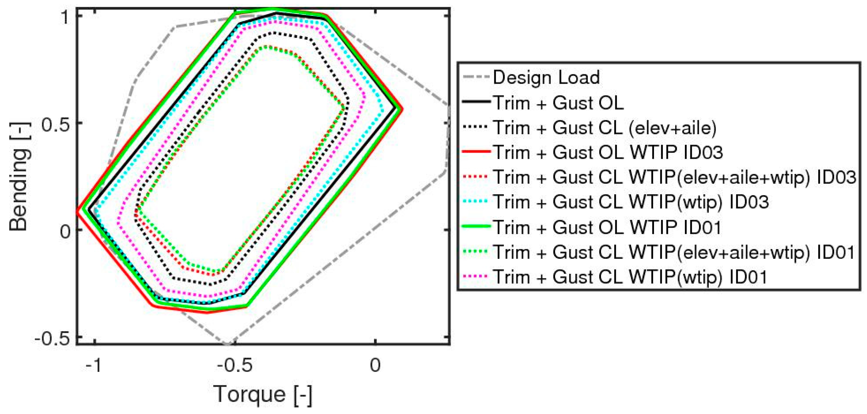
In this preliminary phase, a comparison between a controller using conventional primary control surfaces (ailerons and elevator) and one also using the wingtip was carried out. The controller using all the control surfaces alleviated around 14%, while the one using only conventional control surfaces reached only 7% of WRBM reduction. This proves the enhanced load alleviation capability of a wing equipped with an additional control surface with regard to a conventional wing.
Figure 6 reports a comparison of the load envelopes at the wing root among the different combinations of wingtip configuration and control architecture.
This parametric study allowed us to identify the most promising solutions making a trade-off between the capability of generating a load on the wing root and its cost in terms of actuation effort. The dimensions of the identified solution are reported in
Table 1 and their definition is represented in
Figure 4.
The output of these conceptual and preliminary design phases represents the selected geometry of the wingtip device, which was fed into the next design phase to finalize the design of each single discipline involved.
4.2. Detailed Design
As illustrated in
Figure 3, the detailed design involves five disciplines, which are deepened in the following subsections, except for the aerodynamics since a real optimization was not performed. CFD simulations were carried out for the computation of the aerodynamics loads. The design was carried out in a concurrent way, as the arrows in
Figure 3 highlight: the results obtained in one discipline are fed into the other disciplines to update the models and the results and, in this way, the design is kept up to date and the loop is iterated since a convergence in the models is achieved. In this industrial program, the design was frozen after the critical design review was successfully unmarked.
4.2.1. Aero-Servo-Elastic Design
Since the main goal of the wingtip is to mitigate the dynamic loads due to gusts, a suitable simulation environment is needed to tune the control laws used for both GLA and MLA applications. The available simulation model was the aforementioned stick model (FEM + DLM), but this formulation is not the most convenient for the design of the control laws. Thanks to the aerodynamic matrix identification tool within NeoCASS, based on the matrix fraction approximation described in [
48], it was possible to identify the aerodynamic forces obtained with the DLM as a state-space (SS) model, which was coupled with the structural SS model. In this way, it was possible to realize the SS aeroelastic model of the aircraft.
The design of the control laws was performed on this model, where the dynamic of the actuator is included as a low-pass filter with cutting frequency equivalent to the bandwidth of the real actuator. UMBRA was in charge of partner design and manufacturing of the actuator.
For more details on the design of control laws and the aero-servo-elastic modeling of the SS model, the reader is referred to [
49], and hereafter just a short description of the controller is reported.
The control laws designed for the TP90 aircraft are static output feedback (SOF) controllers, which means that the command to the control surfaces (
u) is a linear combination of the available measures (
y), obtained through a gain matrix (
G), whose elements must be optimized:
. This class of controller does not have any dynamic behavior, hence a time-dependent operation (integral, derivative, filtering, etc.) must be applied before feeding the measure into the
G matrix, noting the “static” nature of such a controller. POLIMI already used this approach for gust load alleviation applications, as well as for active flutter suppression. For the TP90, three different SOF controllers were developed, involving different control surface combinations and different aims. The first controller, named SOF400, was designed for the TP90 with the objective of minimizing the WRBM using the standalone wingtip device. With the same objective, the SOF401 controller was designed, but in this case all the control surfaces were used to improve the WRBM reduction. The SOF003 was designed based on the TP90 aircraft model, but it is oriented to the flight test which will be performed on the C27J, and for this reason a specific constraint of not exceeding the open loop load envelopes in the outer wing part was added. Since the C27J does not have a fly-by-wire system, the control acts only on the wingtip movable surface, without the use of aileron and elevator; moreover, this latest controller embeds both GLA and MLA capabilities. The measures used by the controller are: the pitch rate measured on the center of gravity through an IMU platform and the accelerations measured on the wing’s tips and on the center of gravity, measured with accelerometers. A summary of the developed controllers is reported in
Table 2.
With this simulator, it is possible to perform a gust response evaluating the behavior and the efficiency of different control laws in terms of load reduction. Moreover, from the simulation it is possible to extract the performance required of the actuation system in term of deflection, deflection rate, and torque. As shown in
Section 4.2.2, this information was crucial to size the kinematic and the performances of the actuation system.
Once designed, the controllers were validated on a high-fidelity Simulink model, where other blocks were added to represent the actuators, the sensors, and the control law itself. This Simulink model is the closest possible to the real aircraft, in fact the dynamics of the sensors and the sampling rates matched the ones present on the aircraft. The actuation block was provided by the project’s partner (UMBRA Group) in charge of the development of the dedicated electro-mechanical actuator (EMA), and includes its fully non-linear model, both from a kinematic and a performance (saturations, stall force, etc.) point of view. A simplified scheme of the Simulink model is presented in
Figure 7.
One of the limiting factors for the controller efficiency was the sampling rates of the feedback measures and of the flight control computer (FCC), in fact low sampling rates affect the stability of the controller, reducing the gain margin. For this reason, an investigation of the impact of such frequencies was conducted: the structure of the controller was kept constant, but the gain matrix was scaled by a scale factor. The nominal gains obtained for the reference hardware, namely a low-frequency (LF) controller, were multiplied by 3 when the frequencies were increased 10 times for the high-frequency (HF) controller. The full controller assessment can be found in [
49], while
Table 3 reports the WRBM envelope reductions achieved with low- and high-frequency hardware controllers.
The results obtained show that the usage of a combination of control surfaces is much more effective to control the loads for two reasons: the first one is the biggest surface used at the wing’s tip (aileron + IWT) and the second one is the increased effective arm between the wing’s root and the application point of the control force. Moreover, the FCC and acquisition system rates are key enablers for the development of effective GLA controllers because they directly impact the margin of stability of the closed loop system: higher sampling rates allow increases in the gains (three times in this case) and therefore in the controller performances.
A dedicated SOF controller using only conventional control surfaces was not investigated in detail since the preliminary results in
Figure 6 showed that this layout is not sufficient to target the project requirements (−20% WRBM). The design of a dedicated controller using the IWT only is carried out to assess its standalone alleviation performances (SOF400) and with a focus on the flying test (SOF003), where the conventional surfaces are mechanically commanded by the pilot and hence not exploitable for alleviation purposes.
4.2.2. Actuation and Sensing
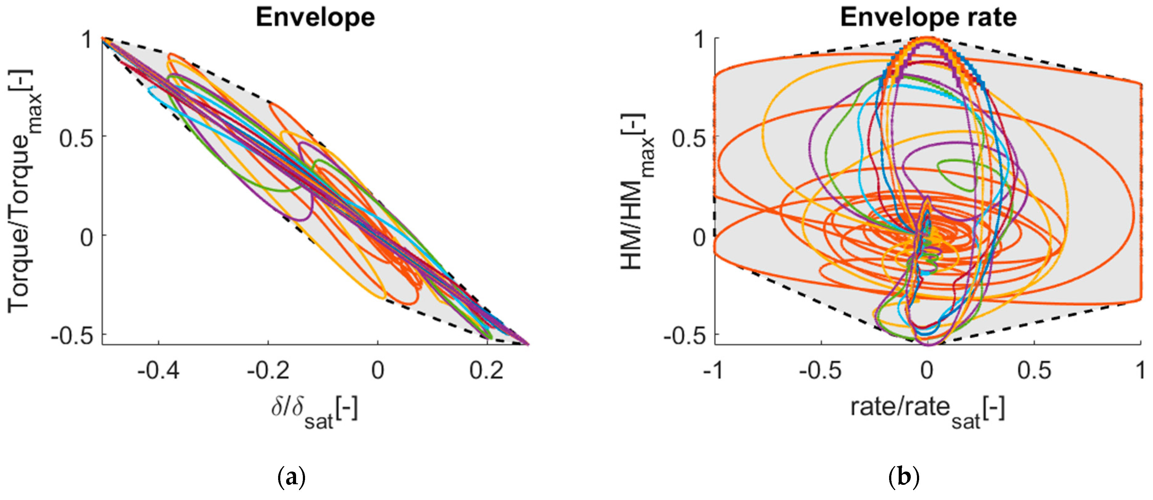
The actuation system plays a major role in the design of an actively controlled system, in fact its performances affect the overall capability of the system in terms of frequency response. A dedicated actuator and kinematic chain were designed in the AIRGREEN2 project, focusing on the maximization of the actuator bandwidth. The actuator is electro-mechanical (EMA), which simplifies the IWT design and installation, avoiding hydraulic piping and the related intricacy. The actuator must produce the motion necessary to achieve the GLA controller command required, under given load conditions (hinge moments). This was translated into designing an actuator that fits the deflection, deflection rate, and hinge moment envelopes obtained with the SS time simulation and is represented in
Figure 8. The results were obtained by testing 10 gusts with the SOF controllers activated and the results for the most demanding controller only are reported.
With such information, together with the internal structural layout, it was possible to optimize the sizing of the EMA and its kinematic. The design of the actuation system was carried out by UMBRA Group, which made a customized design of the EMA for the IWT and for the active winglet [
23] developed in parallel.
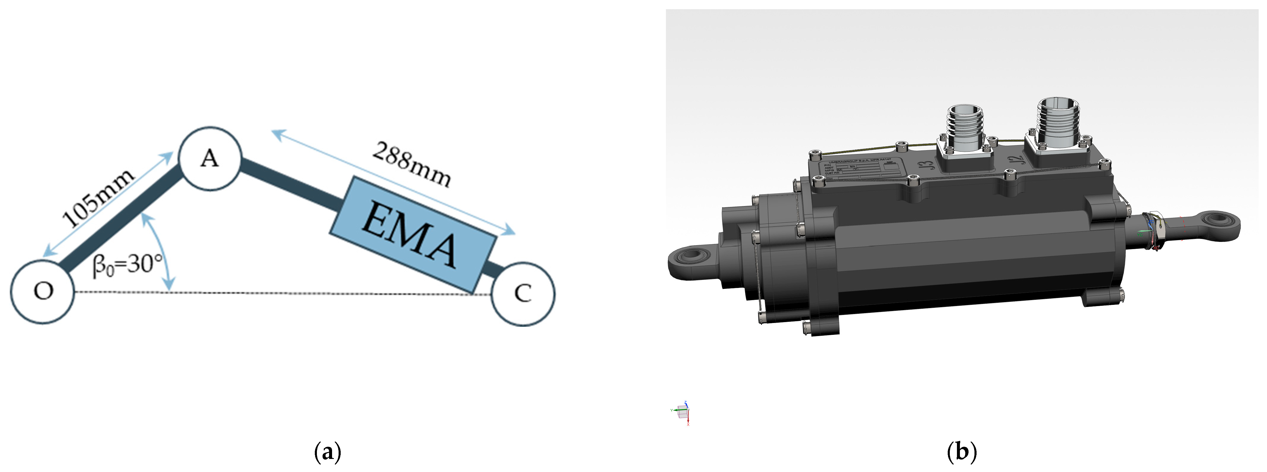
The final geometry is illustrated in
Figure 9a, where the O point is the movable part hinge axis, A is the connection between the actuator stem and the control surface, and C is the connection of the EMA to the fixed portion of the wingtip. This configuration allows a range of motion of ±15°, equivalent to an actuator stroke of 34.74 mm. The EMA’s CAD model is illustrated in
Figure 9b.
Together with the optimized kinematics, the high-fidelity Simulink model of the EMA was delivered and embedded into the Simulink model.
From the sensing point of view, it was necessary to define which were the measures used as feedback for the control laws and which were the associated sampling rates. In addition to the already available pitch rate and center of gravity vertical acceleration, two additional acceleration measures were required to control the flexible wing modes and associated loads. This additional accelerometer was placed corresponding to the elastic axis at the wing’s tip. Since the structure of the controller is a simple gain matrix, the integration of the accelerations to obtain the structural velocities is performed through a set of discrete integrators on the feedback line.
4.2.3. Structural Design
Since the TP90 is simply a numerical aircraft model that does not exist in reality, the structural design was oriented since the beginning to the flying item, the one which will be installed on the C27J. This introduces a retrofitting of the design carried out so far to adapt the wingtip root chord to the C27J wing’s tip chord, which is longer with regard to the TP90. To keep the aspect ratio of the IWT constant, its tip chord is increased as well. The area of the movable surface is kept constant so that the actuation system design is untouched. The result of this operation is an increase in the fixed part projected area.
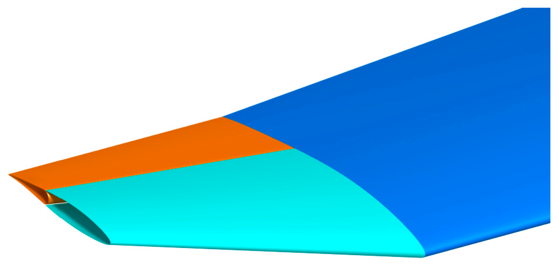
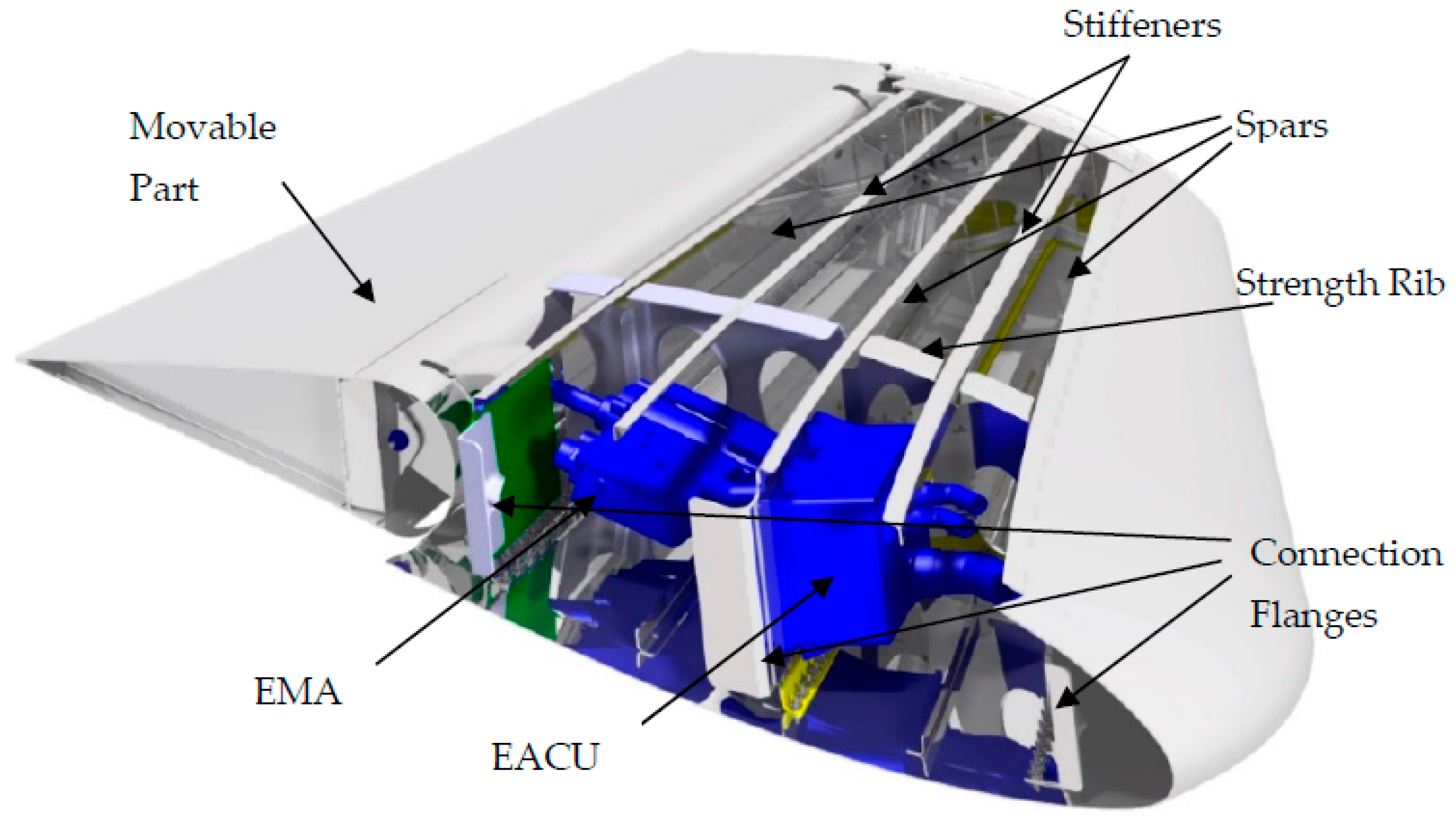
To maintain the continuity with the C27J structural solution, the three-spars concept is extended to the IWT; between the spars an L-shaped stiffener is added. The IWT is divided into two bays delimited by a strength rib that distributes the actuator load across the whole structure. The material used for the wingtip is an aluminum alloy. The detailed structural design, as well as the digital mock-up (DMU), of the IWT, shown in
Figure 10, has been finalized by TECNAM S.r.l., partner of the AIRGREEN2 consortium.
An equivalent global FEM (GFEM) of the DMU was realized in Nastran to perform stress analyses for the evaluation of the failure indexes and linear buckling indexes of the structure under a provided set of load conditions. As owner of the C27J, Leonardo Velivoli provided a set of spanwise distributed load conditions to be verified on the structure, leading to the load envelope represented in
Figure 11. Here are reported only the load cases used for the final stress analysis, but the sizing loads were updated during the project while some modifications were applied to the IWT structure, and the actuation system (as a concentrated mass) was defined. A couple of iterations were needed to reach the convergence of the design to the final layout. The load envelope is composed of 14 load cases that account for trim simulations and gust responses.
The provided internal force distribution is then translated into external load to be applied to the structure. Since in the structural tests (
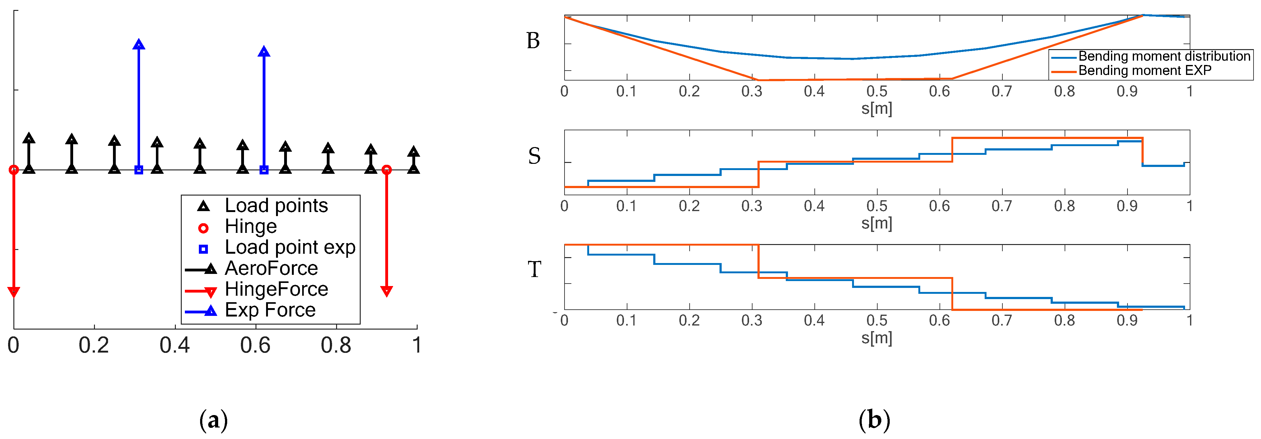
Section 5.3) the demonstrator was loaded at two loading points, i.e., the mid and the tip rib, the same loading station was adopted for the numerical simulations. The loading scheme is schematized in
Figure 12. FEM solvers allowed us to apply whichever load condition (force, moment, pressure, gravity, etc.), we preferred to simulate the same loading conditions that were reproduced in the structural proof tests.
This places the arm between the loading points, respectively at 0.372 m and 1 m, and the wingtip root. It is thereby possible to compute the forces F2 and F1 to be applied in the two loading stations to match the spanwise bending distribution. Once the load magnitude is obtained it is possible to compute the chordwise offsets d1 and d2 to match the torsional moment distribution spanwise. The forces are applied on nodes connected to the structure by means of a rigid element (RBE3)
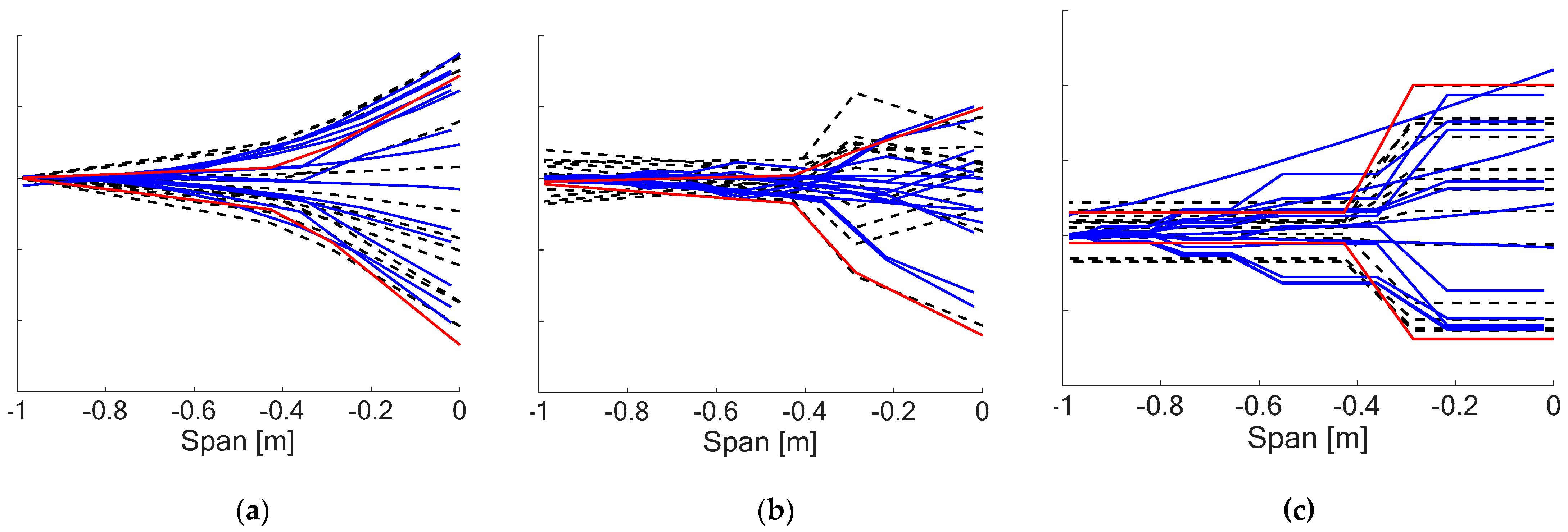
Figure 13 represents the internal forces’ spanwise distribution: the blue lines indicate the distribution provided by Leonardo, the black dashed lines represent the internal forces obtained by applying only two concentrated forces on the structure, while the two red lines are the two load cases chosen for the structural test of the ground demonstrator in
Section 5.3. The two-point loading strategy envelopes all the load conditions for the internal forces, considering that the stress analysis is performed with a linear static analysis and the quadratic failure criterion adopted (von Mises) provides the same results when changing the load sign.
So far, the load conditions refer to the fixed part and, in a similar way, the approach was extended to the movable control surface, where the worst-case load distribution was applied to the FEM of the movable part. This is reported in
Figure 14a where the distributed aerodynamic load on the movable surface is reported by the black arrows while the blue arrows represent the two-point loading strategy adopted for the structural testing of the flap in
Section 5.3.
Figure 14b compares the internal forces’ distribution obtained by applying the ten forces provided by Leonardo and the two forces used for the test. The two-point loading internal forces are higher with regard to the one obtained with the distributed aerodynamic forces; hence, they are conservative.
The 14 load conditions provided were applied to the structure to evaluate the margin of safety (MoS) of the metallic part, computed as
where the VM subscript indicate the von Mises stress. The analyses were performed with Nastran, solving a linear elastic static case (SOL101). Since the von Mises stress is the results of a non-linear combination of the stress state in the elements, the MoSs were computed both for the limit and ultimate loads, computed with a safety factor of 1.5. In the nominal condition, a MoS larger than 2 is obtained and in the ultimate case MoS is satisfied as well. The MoSs are plotted in
Figure 15a, while
Figure 15b represents the most critical condition envelope.
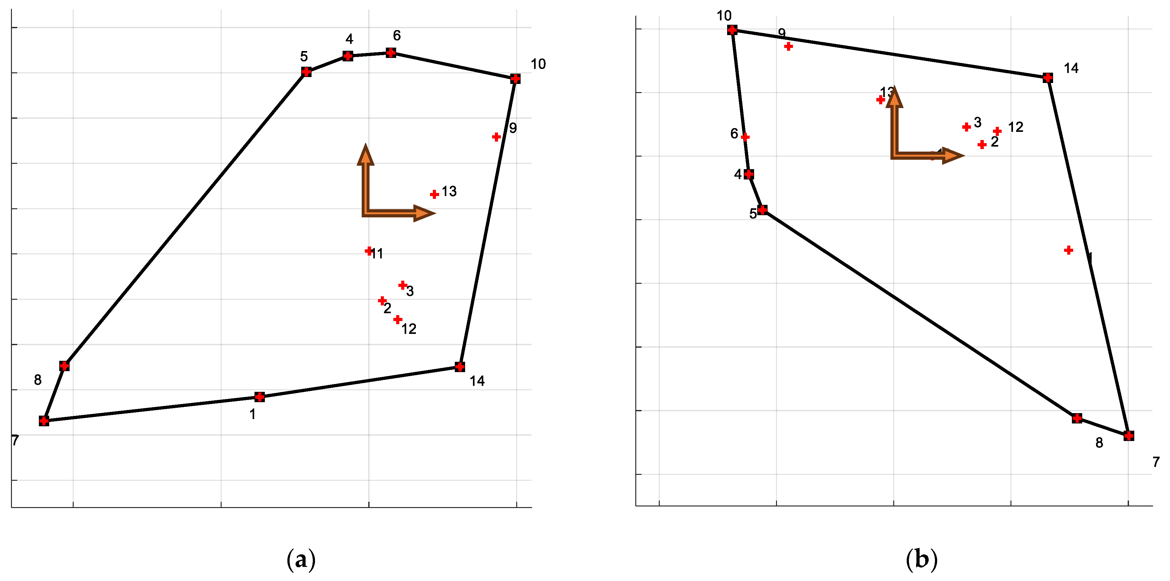
Besides the static solution, a linear buckling analysis was performed as well to assess the structural stability of the IWT under the prescribed load. In this case, Nastran’s linear buckling solution (SOL105) was used. In the nominal case, the minimum eigenvalue found for the whole load envelope is
, meaning that the structure is far from instability.
Figure 16a shows the von Mises’s stress envelope for the first buckling mode, while
Figure 16b shows the buckling mode.
In addition to these analyses, several others were performed with the FEM, like hinge stress distribution and lug verification, actuator runaway, and end stop sizing. The connections between the structural part (rivets and bolt) were verified as well using analytical methods; in this case, a safety factor of 1.5 and an additional fitting factor of 1.15 were used. No connection was critical in the analyses performed.
The numerical structural analyses showed that the item designed for the flight test is safe and neither failures nor buckling occurred, then the structural configuration was frozen and the obtained masses, opportunely scaled to the TP90 wingtip dimensions, were updated in the aero-servo-elastic model for a final verification loop.
5. Experimental Testing
The different technologies developed in the AIRGREEN2 project were tested at different levels and with different aims before the finalization of the flying item. Three main tests were conducted: the first one was an aero-servo-elastic wind tunnel test on a scaled model (1:6) to assess the effectiveness of the developed GLA controllers, the second one was a purely aerodynamic wind tunnel test of a scaled model (1:3) to verify the aerodynamic performances of the wing and its innovative devices, and the last one was a structural integrity test performed on a prototype of the flying IWT, named ground demonstrator (GD), that was necessary to achieve the permit to fly for flight tests. In the following, each of the tests is briefly described.
5.1. Aero-Servo-Elastic Wind Tunnel Test (WTT3)
For this test, an aero-servo-elastic 1:6 scaled wind tunnel half-model, representative of the TP90, was designed and built [
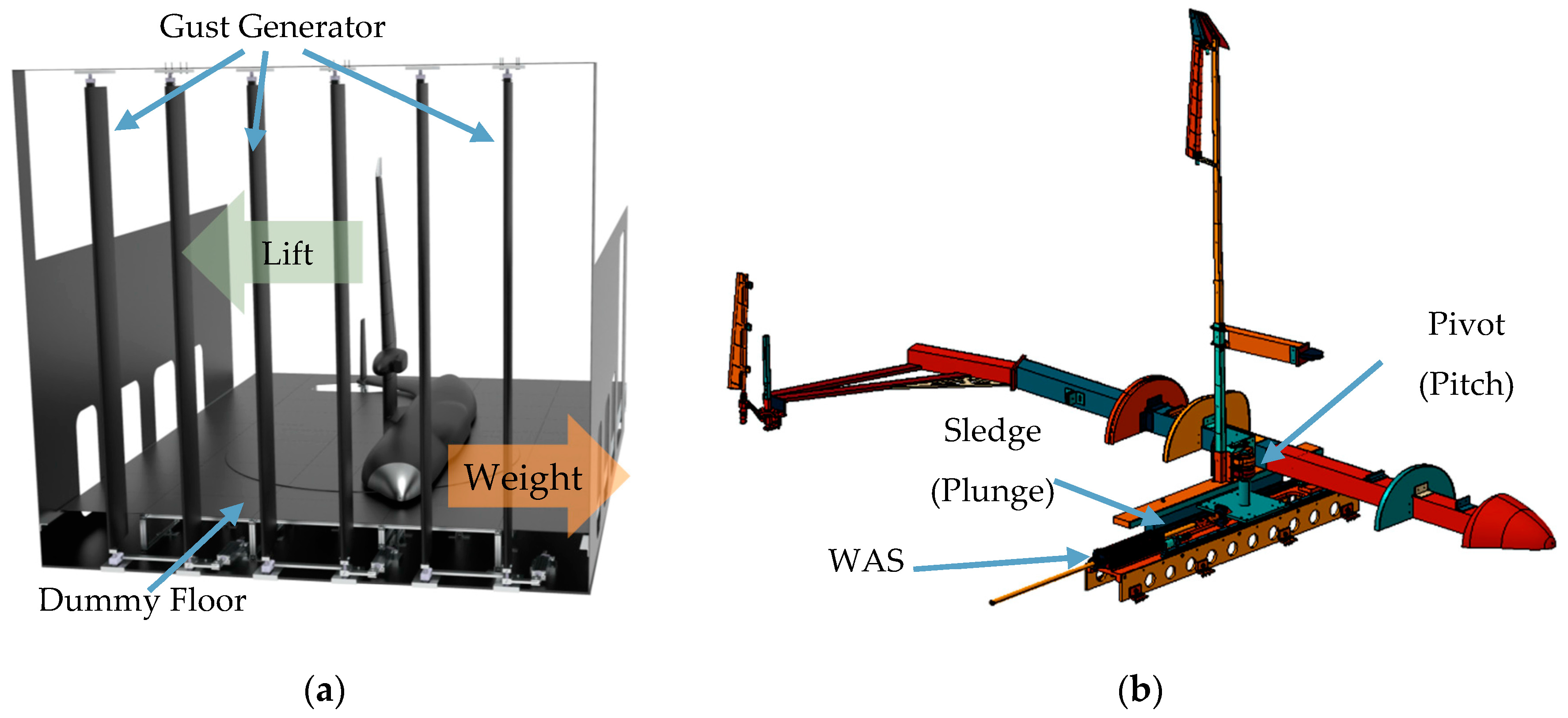
50] and called WTT3. The half-model is vertically mounted, and the free body motion (plunge and pitch) is preserved thanks to a pivot–sledge mechanism. The scaling law adopted, based on the iso-frequency approach with respect to the full-scale aircraft, allows the time scale to stay constant, since the velocity and length scaling factor are the same. This is a key feature of the model because it allows us to plug-and-play the control laws designed for the real aircraft on the wind tunnel model, only a scaling factor on the acceleration must be applied but the dynamic behavior is the same of the reference aircraft. In this way, the WTT3 became the test bench for the validation of the GLA control laws, where the gust can be reproduced by a gust generator [
51] in a controlled and repeatable manner. The model is equipped with accelerometers used both for measure and control purposes, strain gauges to measure the wing loads spanwise and a measure of the pitch rate. Since the model is vertically mounted, Froude’s scaled gravity force is introduced by a long-stroke electro-magnetic actuator placed below a dummy floor and acting on the model’s center of gravity; this system was named the Weight Augmentation System (WAS) and allows trimming of the aircraft for different load factors. The WTT3 test configuration allows performance of the aero-servo-elastic response of a free flying aircraft in cruise conditions, thereby producing the 1 g trim loads associated with the trim plus the dynamic loads due to the gust, exactly as in reality. The scheme of the WTT3 model is depicted in
Figure 17.
From the sensing point of view, the acquisition rates and flight control computer frequency are the same as for the real aircraft, but they can be modified to study the impact of these parameters on the controller effectiveness.
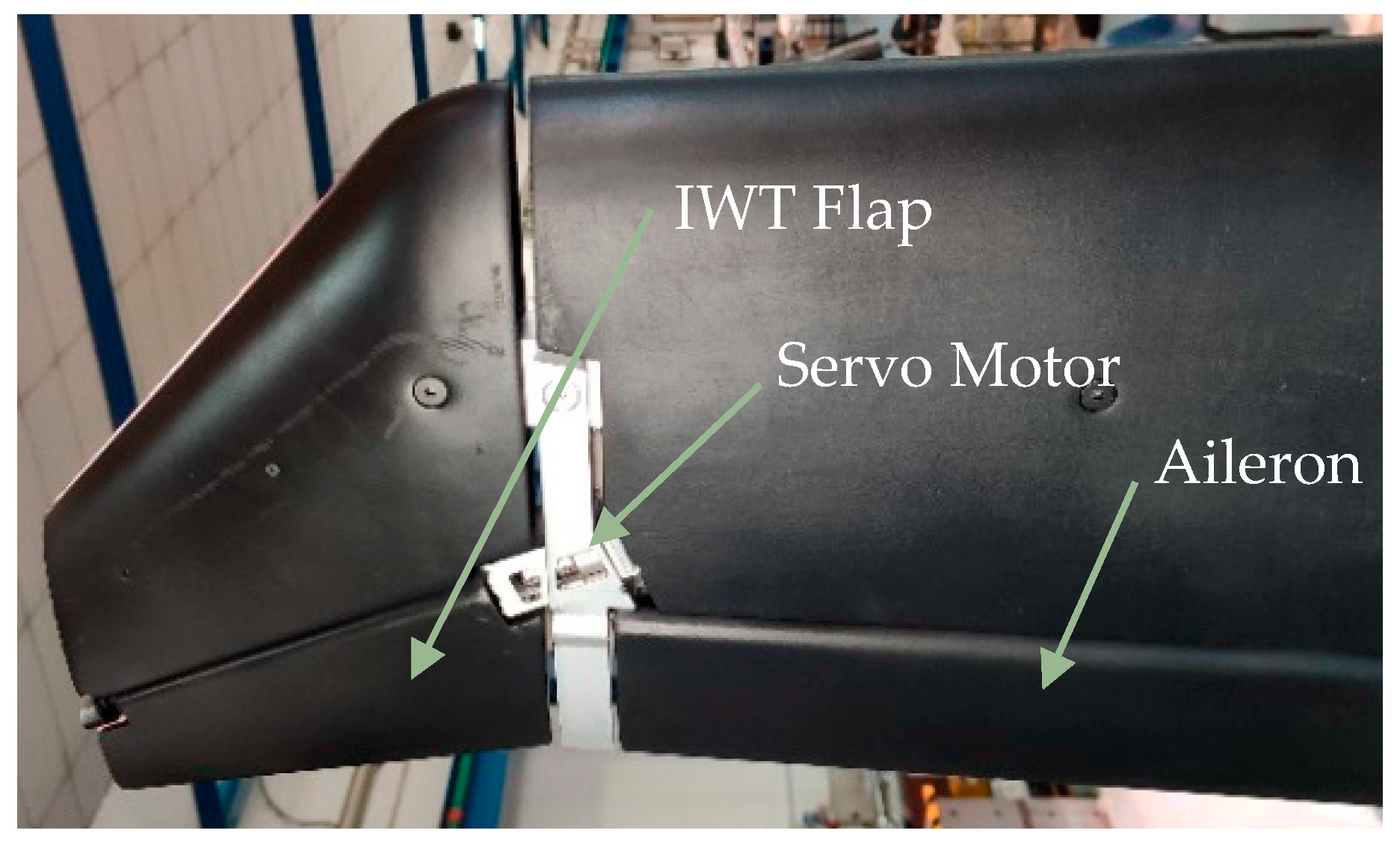
The control surfaces are servo actuated using harmonic drive electric motors [
52] and the bandwidth of the actuators is tuned to match the dynamic of the real actuators.
Figure 18 shows the detail of the WTT3 wingtip device and the servo motor.
During the test campaign, the three different controllers described in
Section 4.2.1 were tested, focusing on two gusts: one tuned with the first bending mode of the wing and the other one on the frequency that produces the highest WRBM, in fact the gust amplitude was scaled following EASA regulations [
53].
Since the flight point chosen is at the corner point for maximum operative speed (VMO) and dive speed VD), the gust amplitudes were corrected to have the same gust velocity in equivalent air speed (EAS).
In the following, the two gusts will be named tuned and max WRBM. The gusts were tested with both positive and negative amplitudes at two different flight speeds equivalent to maximum operative and dive conditions, for a total of eight gust conditions for each controller.
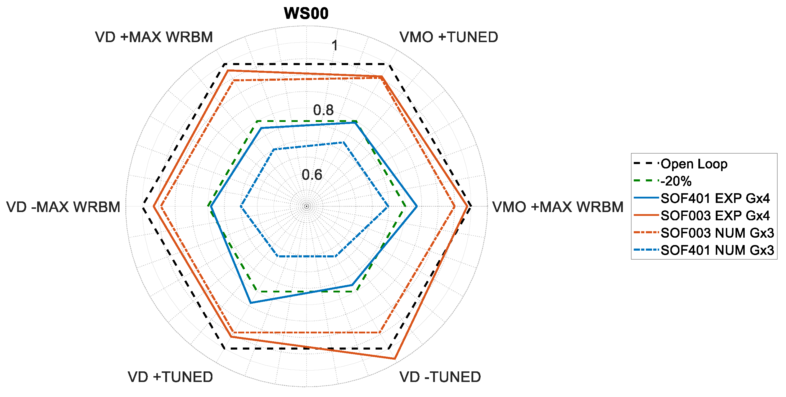
The results obtained in terms of alleviation were below the numerical values obtained in
Section 4.2.1, mainly due to a loss of control surface efficiency in the wind tunnel, as shown in [
49,
54], which was estimated as a 25% reduction of the transfer function between the IWT rotation and the wing’s tip acceleration. This was recovered by applying a scaling factor of 1/0.75 on the SOF gain matrix to compensate for the efficiency reduction. The comparison between the numerical and experimental results is reported in
Figure 19, for the high-frequency controller with increased gains; SOF003 HF (IWT only) reductions are similar for the two cases, while SOF401 HF (all surfaces) behaved worse than predicted, mainly due to a friction issue related to the pitch motion that strongly impacts on the elevator deflection for the pitch mode control. Anyway, the experiments showed that with adequate electronic hardware and when using a combination of all the control surfaces, a 20% WRBM reduction is achievable.
5.2. Aerodynamic Wind Tunnel Test (WTT2)
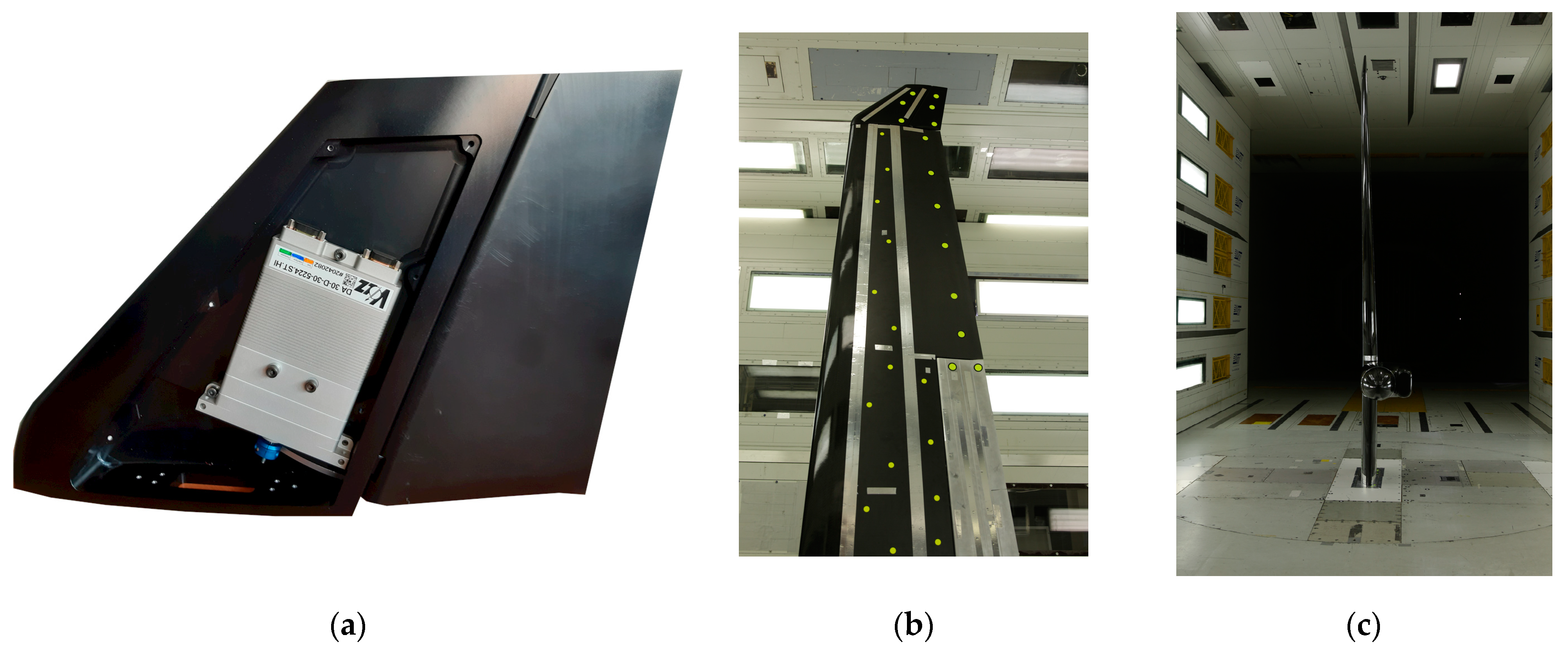
A 1:3 scaled wind tunnel model, named WTT2, was designed and tested in a transonic wind tunnel at DNW to assess the aerodynamic performances of the devices developed in the framework of the AIRGREEN2 project; among them there was the IWT as well. Since there were no particular requirements in terms of stiffness and mass, the IWT was milled from an aluminum block and its movable surface was commanded with a servo motor, as shown in
Figure 20a. The motion is transferred to the IWT flap through a crank–arm mechanism. The assembled model (>5 m) span is shown in
Figure 20b, where it is possible to notice the morphing flap as well (metallic part on the lower-right portion of the wing).
The results in terms of aerodynamic performances are confidential, hence no polar curve can be reproduced in this document. The aim of this section is to show that even the aerodynamic aspect of this device was assessed in the design, despite its primary function being devoted to the load alleviation and not to the improvement of the aerodynamic efficiency.
5.3. Ground Demonstrator (GD) Structural Integrity Test
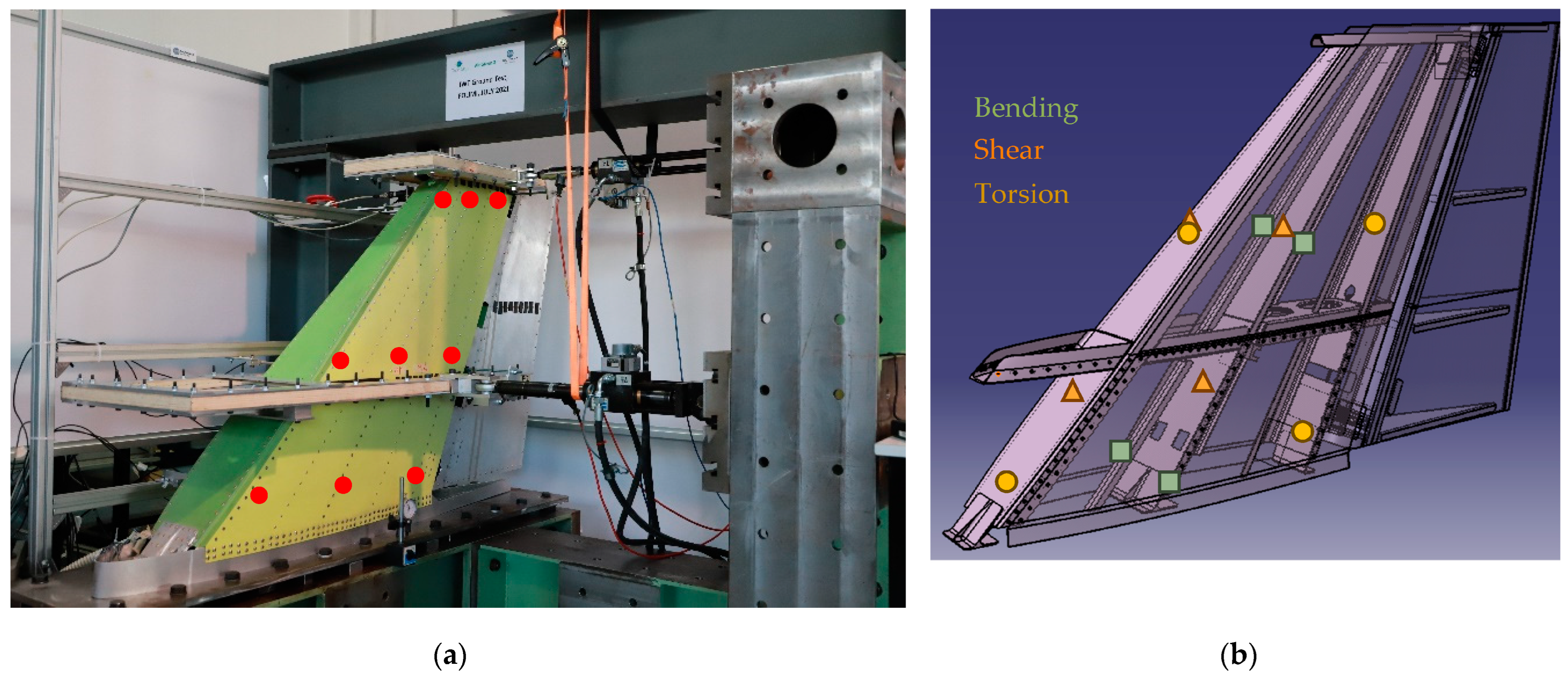
The final test before the flight was the static test of the IWT retrofitted for the C27J, that took place at POLIMI in August 2021. The left wingtip item was assembled with all its structural parts, except the leading edge and the tip cover with the position light. A dedicated self-sustained test rig was designed to clamp the wing with a dedicated interface plate and to fix the hydraulic actuators used to introduce the force. The loads were introduced into the structure at two points through wood load saddles, placed spanwise and corresponding to the mid and tip ribs. The displacements of nine points were measured with an array of linear potentiometers. Two spanwise monitoring stations were equipped with strain gauges, connected to create eight Wheatstone’s bridges to measure shear (four measures), bending (two measures), and torsional (two measures) strains. The bridges have been checked in terms of functionality by TECNAM S.r.l., who installed them inside the IWT before closing the upper and lower skin panels. Then, once the installation on the test rig was completed, it was calibrated by a series of unitary single loads (using only one actuator) generating known internal loads to obtain the load–strain relations.
Figure 21a shows the GD mounted on the test rig with the actuators connected and the points where the displacements were measured, while
Figure 21b shows the strain gauges’ layout.
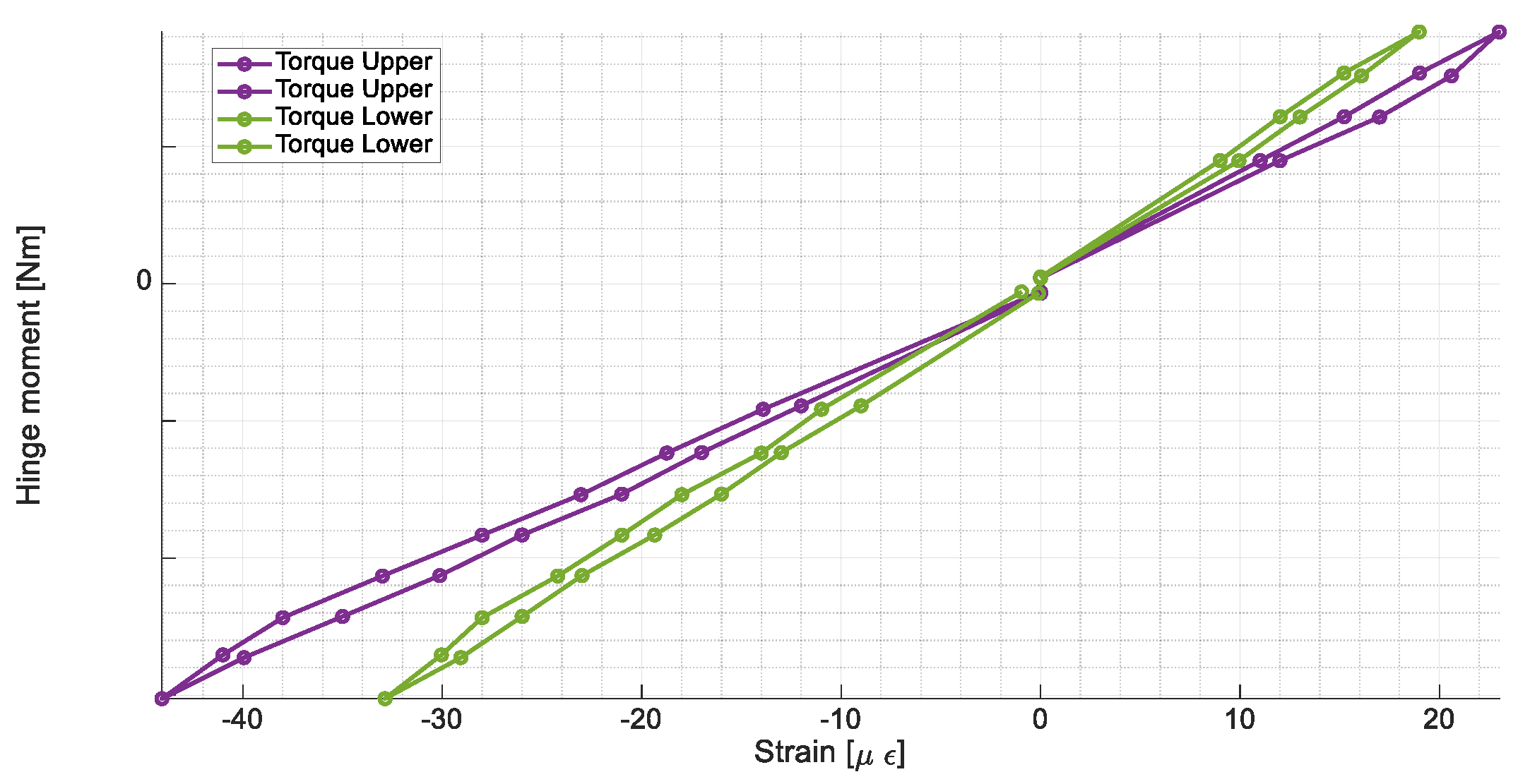
The measures acquired were needed to prove the linear behavior of the structure up to the limit loads and the functionality of the control surface and to validate the numerical predictions. The two worse load conditions, one for upward and one for downward load conditions, were considered. A preliminary load test with up to 70% of the maximum load was carried out to stabilize the structure in terms of residual backlash in the connections coming from the assembly process. After that, the real test was performed following a stepped pyramidal load profile, with a 10% load increment for each step that was held for two minutes, allowing the structure to settle in the new configuration. The same loading profile was maintained in the loading and unloading process to investigate if hysteresis was present (buckling) and, most importantly, that no permanent deformations were produced (no yielding). The same approach adopted for the fixed IWT structure was used to test the movable surface; in this case, the actuator was replaced by a rigid rod to hold the flap at 0°. Even in this case, neither permanent deformation nor buckling was detected for the structure. The measure of the hinge moment was derived by two different Wheatstone’s bridges applied on the upper and lower surfaces of the control surface, without the need for instrumenting the actuator. The results are presented
Figure 22, where the hinge moment can be estimated from the measured strain.
6. Conclusions and Future Works
This paper summarized the design activity performed in the framework of the Clean Sky 2 AIRGREEN2 project. The development of the active innovative wingtip device covered in a concurrent and interconnected way several technical disciplines, providing a TLR6 item ready for flight tests. The design of the item is more oriented to the GLA purpose; hence, the aerodynamic design is not heavily stressed. The project covered not only the design part of the IWT, but also the testing at several levels of both scaled models (WTT2 and WTT3) and a real prototype (GD) to fully characterize the aero-servo-elastic behavior, the aerodynamic performances, and the structural integrity in real conditions. The gust load alleviation capabilities of such a device can reach 4% to 10% WRBM reduction when used in a standalone configuration, reaching 17% reduction when used in combination with other control surfaces. Furthermore, the same device can be used for maneuver load alleviation, reducing the trim loads. The load envelope reduction has a direct impact on the wing sizing, and the results obtained show that dedicated control surfaces may help in achieving it for the dynamic loads. With a near future perspective, this technology together with a regulation revision for the load alleviation application may lead to the design of lighter structures and hence improve the fuel burn and related GHG emissions. With a shorter-term vision, the application of GLA reduces the wing loads, improving the fatigue behavior of the structures, increasing the time intervals between inspections, and extending the operative life of the aircraft.
Concerning the adopted concurrent approach, and the impact of variable requirements on the design of the device, surely the most challenging aspect was related to the need to design a control device originally conceived for an aircraft and making it compatible with another one, significantly different, to be used for flight testing. The result is that the final IWT cannot for certain be considered as optimal but maybe just suboptimal.
Finally, some remarks about the role of aeroelastic wind tunnel testing carried out for this project. Even in the case of a low-velocity test like the ones achievable in POLIMI’s wind tunnel, the aeroelastic wind tunnel tests represent an extremely important step in the development of active control solutions and can be used as a real design tool. Specifically, for the IWT development and related active control architectures, the advantages of using iso-frequency scaling allowed us to test exactly the same active control system, including the actuator non-linear model, developed for full-scale aircraft and finally implemented on the flying bed. A very important aspect was related to the evaluation of the hardware characteristics, such as data transmission rate, number of sensors and their bandwidth, and the control loop frequency. The final alleviation results supported LDO in the selection of the hardware to be used during the experimental validation on the flying testbed. The gain matrices identified during the wind tunnel test campaign have been transferred to LDO for the final testing on the iron bird before starting the flight test campaign.
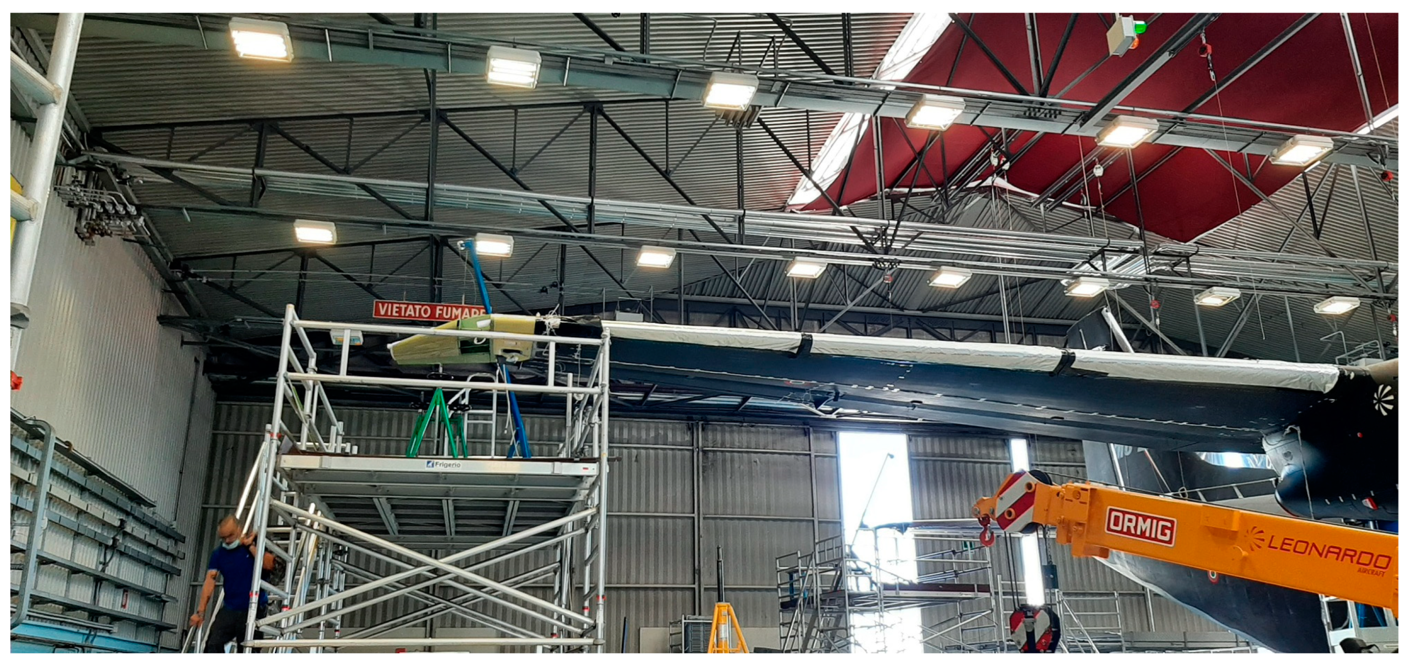
The flying IWTs were mounted on the C27J for their qualification and the GVT of the complete aircraft, as shown in
Figure 23.
The research program will end in 2023 with the flight test on a C27J aircraft, where the behavior of the active IWT will be assessed in a relevant operative environment, increasing its TRL.
In terms of future work, after the completion of the activities it will be possible to perform a final assessment and draw the final conclusions about the potentialities of the proposed device. It is well known that any active control system must be evaluated not only in terms of its performances but in comparison with the possible penalties such as weight penalty, complexity, and safety-related issues. The IWT was originally designed for the TP90 aircraft, that is just a numerical aircraft model originally designed with a conventional winglet. Most importantly, after the preliminary design review, the development of the IWT for TP90 was stopped and the activity shifted to the development of the version adapted for C27J in view of the flight test validation. No structural optimization has been applied, and the IWT device was designed to demonstrate its functionality in flight. Any realistic comparison between weight penalty and improved performances appears at this stage misleading. However, it is believed that the most relevant benefits of this kind of device can be obtained when it is designed together with the wing. The retrofit application could be an option but for certain not the most promising in terms of potential benefits.
Disclaimer: The present work reflects only the authors’ view and the European Commission and Clean Sky 2 JU are not responsible for any use that may be made of the information contained in this paper.
