Abstract
Ammonia dinitramide (ADN)-based liquid monopropellants are considered to be environmentally friendly alternatives to the toxic and carcinogenic hydrazine-based propellants. Hence, Space Solutions Co., Ltd. is developing a 1N ADN-based liquid monopropellant thruster by conducting a combustion performance in different types of reactors. Various parameters, such as preheating temperature and the size of thermal and catalyst beds, were examined. The results showed that the decomposition of the propellant in a Pt-LHA catalyst bed, which was used in the Type-1 reactor, resulted in insufficient combustion at low preheating temperatures. Furthermore, increasing the preheating temperature led to partial reaction of the propellant, but resulted in low combustion efficiency due to disintegration of the catalyst. However, when a thermal bed (STS ball) was used in addition to the catalyst bed (Pt-LHA) in the Type-2 and Type-3 reactors, the combustion efficiency was improved, with a minimal pressure drop of 0.2 bar. It was also confirmed that the catalyst was not damaged even after repeated operations. In conclusion, this study suggests that the propellant needs to vaporize before decomposing on the catalyst bed to achieve optimal combustion efficiency.
1. Introduction
Ammonium dinitramide (ADN)-based liquid propellants, such as LMP-103S and FLP 106, are being used as environmentally friendly monopropellants for satellites [1,2,3,4]. LMP-103S consists of 63% ADN, 14% water, 18.4% methanol, and 4.6% ammonia, while FLP-106 consists of 64.6% ADN, 23.9% water, and 11.5% mono-methylformamide (MMF) [5]. The main component of the propellant is ADN, which is an energetic ionic salt that generates non-toxic gaseous products upon combustion [6]. These green monopropellants serve as alternatives to the hydrazine-based fuels. Hydrazines are the commonly used propellants in space launch vehicles and satellite propulsion systems [7]. However, hydrazines are toxic and corrosive fuels that pose hazards during handling and storage [8]. A SCAPE suit is required for fueling with hydrazine and thus increases mission costs. The European Union classified hydrazine as a substance of very high concern (SVHC) under the REACH (Registration, Evaluation, Authorization, and Restriction of Chemicals) regulation in 2011 [9]. Therefore, the development of environmentally friendly monopropellants is a highly demanded research area in space science. LMP-103S and FLP106 have emerged as promising green monopropellants and alternatives to the hydrazine fuels in recent years. LMP-103S, manufactured by ECAPS, was first used in space in the mango-PRISMA satellite in 2010 [10,11]. Similarly, FLP-106, developed by the Swedish FOI (Swedish Defense Research Agency) in cooperation with SSC (Swedish Space Corporation), is a mature propellant blend [12]. Compared to hydrazine, LMP-103S offers improved performance, with a specific impulse of 6% or higher and a propellant density 24% higher [13]. Similarly, FLP-106 also provides a higher specific impulse [14]. Therefore, satellites can either have smaller tanks or extend mission durations while maintaining the same tank size. The fueling procedures for LMP-103S are much simpler, requiring only normal protective clothing for chemical handling. This makes pre-launch fueling faster and less expensive. Unlike hydrazine, LMP-103S is also insensitive to air and humidity, making it easier to handle and de-fuel, if necessary. Currently, Bradford ECAPS is providing green propulsion systems for earth observation satellites such as SkySats [2]. The Lithuanian company, Nano-Avionics, has developed an ADN-based Cubesat propulsion system [15]. Additionally, the Beijing Institute of Control Engineering (BICE) has developed green propellant thrusters with thrusts of 0.2 N, 1 N, 5 N, and 20 N [16]. Therefore, ADN-based propulsion systems have become widely interesting and reliable for the space community. However, new players in the space field who aim to become self-reliant are also showing interest in developing green propulsion systems for satellite applications.
One such example is Space Solutions Co., Ltd. Daejeon in South Korea, which is researching ADN-based monopropellant thrusters for satellite applications. We are considering a similar fuel composition to that of LMP-103S for the 1 N monopropellant thruster. Additionally, numerous studies on ADN-based monopropellants have been published by various research groups [12,13,17,18,19,20,21,22,23,24,25], which helps to set the parameters for thruster development. We can also gain valuable insights that can minimize the time required for development. However, the development of monopropellant thrusters is still a complex process and each and every test of the development process must be experienced. Therefore, in this paper, we focus on the development of a 1 N ADN-based green monopropellant thruster for satellite applications by considering the reactor structure and preheating temperature.
2. Materials and Methods
2.1. ADN-Based Monopropellant
A liquid monopropellant based on ADN was prepared using chemicals such as ammonium dinitramide (ADN, FOI), methanol (Sigma-Aldrich, Seoul, Republic of Korea, HPLC, ≤99.9%), 28–30 wt% ammonia solution (Samchun, Seoul, Republic of Korea), and deionized water. The composition of the liquid monopropellant was similar to that of LMP-103S liquid propellant (Table 1), and its density, as measured using gravimetric analysis, was almost identical to that of LMP-103S (1.24 kg/L).

Table 1.
Composition of ADN-based monopropellant.
2.2. Catalyst
The support material, lanthanum hexaaluminate (LHA), was prepared by impregnating lanthanum nitrate (Sigma, Seoul, Republic of Korea) on gamma alumina pallets (mesh 16–20, Merck, Seoul, Republic of Korea) using a wet chemical method. The impregnated material was calcinated at 900 °C with a heating rate of 2 °C/min and an isothermal temperature of 2 h. The catalyst was further sintered at 1400 °C with a heating rate of 5 °C/min and an isothermal temperature of 4 h. The active material, platinum (Source: Chloroplatinic acid, PGM Research 95%), was impregnated on LHA using a wet chemical method, and Pt-LHA was calcinated at 600 °C with a heating rate of 2 °C/min and an isothermal temperature of 4 h. Figure 1 and Figure 2 represent the surface images of the Pt-LHA catalyst. A white spots on the catalyst confirm the deposition of Pt on the LHA surface. Furthermore, the surface area measured using BET was 7.8 m2/g.
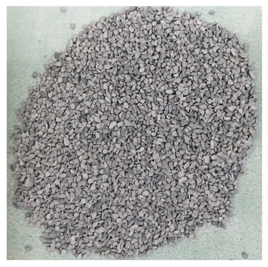
Figure 1.
Image of the Pt-LHA catalyst (10 wt% Pt).

Figure 2.
SEM images of the Pt-LHA catalyst (10 wt% Pt).
Figure 3 shows the DSC-TGA analysis results of the ADN-based monopropellant with the Pt-LHA catalyst. Rapid heat generation and weight reduction were observed at 150 °C, confirming the effectiveness of the Pt catalyst in decomposing the ADN-based monopropellant.

Figure 3.
DSC-TGA graph of ADN-based monopropellant with Pt-LHA catalyst.
2.3. Reactor Design
The reactor used in this study was designed to provide a thrust of 1 N and a combustion chamber pressure of 10 bar, as presented in Table 2. The theoretical specific impulse and characteristic velocity of the monopropellant were investigated, and assuming a nozzle expansion ratio of 100, the theoretical specific impulse was found to be 268.5 s, and the characteristic velocity was 1389.7 m/s. The diameter of the nozzle throat was calculated to be 0.82 mm using CEA calculation, and the heat of formation of ADN in liquid was −110.22 kJ/mol.
Table 2.
Design parameter of reactor.
The reactor was manufactured up to the nozzle throat without expansion of the nozzle because it was intended for basic research and not considered a vacuum environment. The injector orifice for propellant injection was designed with a diameter of 0.16 mm to ensure ease of manufacture. The reactor structure consisted of three main components, including an injector plate for propellant injection, a reactor for decomposing the monopropellant, and a combustion chamber that was connected to a nozzle. Each element was manufactured in a flange type to allow for easy separation and assembly, and a graphite seal was used due to its excellent chemical and thermal resistance, which maintained gas tightness considering the temperature and pressure conditions of the reactor. Sensor ports were fitted to the reactor and combustion chamber to allow for measurement of pressure and temperature (Figure 4).

Figure 4.
Representative 3D model of Type 1 reactor.
Three types of reactors were considered for experiments. For reactor Type-1 and Type-2, one reactor structure was used, but for Type-3, two reactor structures were serially connected. Therefore, the dimensions of reactor Type-1 and Type-2 were the same, but the length of reactor Type-3 was double that of Type-1 and Type-2 (Figure 5). In the Type-1 reactor, only a catalyst bed (LHA) was used to investigate the decomposition feasibility of the ADN-based monopropellant. In Type-2 and Type-3 reactors, both a thermal bed and a catalyst bed were employed. The total length of Type-1 and Type-2 reactors was 30 mm, and the Type-3 catalyst was 60 mm.
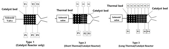
Figure 5.
Images of different types of reactors (P: pressure sensor, T: Temperature sensor).
2.4. Experimental Setup
The reactor test was configured as shown in Figure 6. The liquid propellant was pressurized using gaseous nitrogen, and the flow rate of the propellant was measured using an orifice mass flow meter. A propellant was supplied to the reactor using a solenoid valve, and pressure and temperature were measured through a sensor port installed to the reactor and combustion chamber. The pressure was measured using Kulite ETM-375 (1000 psia), and the temperature was measured using an R-type thermocouple.

Figure 6.
Schematic of ADN based propulsion system.
3. Results and Discussion
The decomposition of ADN-based monopropellant can be achieved through thermal and catalytic processes [26,27,28,29,30]. However, thermal decomposition without a catalyst yields low efficiency. On the other hand, propellant decomposition using a catalyst offers higher efficiency but requires a preheating temperature to activate the catalyst. In this paper, we studied three types of reactors (reactor Type-1, Type-2, and Type-3) to investigate the thermal and catalytic decomposition of the propellant.
3.1. Type-1 (Catalyst Reactor)
A 30 mm reactor length containing LHA catalyst bed was installed and used to study the decomposition behavior of ADN-based monopropellant. Several experiments were performed at different preheating temperatures (Table 3). The lowest preheating temperature of the reactor was 269 and fired for 0.3 s. It was found that the propellant could react with the catalyst at that temperature with some initial cooling of the catalyst. It exhibited a very low reactivity and a low chamber pressure of 1.58 bar. A representative example containing a low preheating temperature is presented in Figure 7. In that example, the catalyst bed was preheated to a temperature of 320 °C. Then, the propellant was injected for 5 s. It was observed that the decomposition of the propellant occurred, and the combustion chamber pressure initially rose to 3.5 bar and then decreased after the continuous propellant injection (Figure 8a). The upstream temperature (T1) of the reactor decreased to 60 °C from 320 °C, while the downstream temperature (T2) of the catalyst bed of the reactor increased to 500 °C and then decreased again. This indicates that the propellant absorbed heat when passing from T1 to T2, initiating decomposition, causing the temperature rise of T2 to around 500 °C (Figure 7b).
Table 3.
Conditions and performance results of Type-1 reactor test.

Figure 7.
Reactor test of Type-1, 7th pulse, heating temperature 320 °C, valve operation 5 s (107 s~112 s): (a) pressure result; (b) temperature result.

Figure 8.
Reactor test of Type-1, 12th pulse, heating temperature 500 °C, valve operation 3 s (180 s~183 s): (a) pressure result; (b) temperature result.
In addition, it can be interpreted since the propellant absorbed heat at the T1 catalyst bed and the temperature declined below 60 °C, even with the preheating temperature above 300 °C, which did not allow the propellant to react with the catalyst at T1. However, after absorbing heat at T1, the propellant passed to T2 and reacted with the catalyst; the temperature increased. This means that the decomposition reaction started at the midstream of the catalyst bed. However, the desired pressure and temperature of the catalyst reactor T2 were not achieved, and consequently, the chamber pressure was lowered. Furthermore, it was observed that the propellant slowly reacted in the catalyst bed even without propellant flow and suddenly, a pressure spike was observed at 116 s (Figure 7a). Hence, it can be confirmed that the preheating temperature of 320 °C was not sufficient for steady-state decomposition of the propellant using only the catalyst bed. Therefore, it was necessary to increase the preheating temperature of the catalyst.
In the next experiment (Figure 9), the catalyst bed was preheated to a temperature of 500 °C, and the propellant was injected for 3 s. After the propellant was injected, the combustion chamber pressure rose and maintained at 4 bar (Figure 9a). During this time, the temperature at T1 decreased from 500 °C to 170 °C, while the temperature at T2 increased from 430 °C to 1070 °C (Figure 9b). Since the minimum temperature of T1 was 150 °C or higher, the liquid propellant passing through the injector at T1 may have had a catalytic reaction. Therefore, it may be confirmed that the propellant started to decompose at T1 even with cooling. Further propellant decomposition was observed by confirming the highest temperature at T2.

Figure 9.
Reactor test of Type-1, 19th pulse, heating temperature 520 °C, valve operation 3 s (268 s~271 s): (a) pressure result; (b) temperature result.
Additionally, another pulse of 3 s revealed continuous steady-state firing (see Figure 9), similar to Figure 8. The chamber pressure was increased to 4 bar, and the temperature reached up to 1070 °C at T2. However, the target chamber pressure (P3) was 10 bar; the temperature was also significantly lower than the theoretical decomposition temperature. Therefore, it was necessary to improve the combustion of propellant by changing the reactor parameters.
The pressure drop is another significant factor to know about the combustion performance. The pressure drop between catalyst bed and chamber pressure was measured. Figure 10a shows the pressure drop between the downstream (P2) of the catalytic reactor and the combustion chamber (P3) according to number of pulses. In the first pulse, the pressure drop was 1.5 bar, but from the second pulse, the pressure drop rose sharply and reached up to 12 bar. The increase in pressure drop as the test progressed can be explained by the catalyst being broken or sintered, so the cross area of the flow path for the propellant was decreased.

Figure 10.
Summary of test result of Type-1 reactor: (a) pressure drop between catalytic reactor (P2) and combustion chamber (P3) by number of operations; (b) rise time of T2 temperature according to T1 preheating temperature.
Figure 10b summarizes the rising time with respect to the preheating temperature of the Type-1 reactor. Rising time is the time required to increase to the highest temperature at T2. It may determine the effect of preheating temperature on decomposition of propellant. The faster the reaction rate means the shorter the response time. It was observed that the rising time decreased when the preheating temperature was above 400 °C. Conversely, a slow reaction rate was observed below a preheating temperature of 400 °C and vice versa.
In addition, in order to compare the reaction rate according to the preheating temperature of T1, Figure 10b shows how fast the temperature of T2 rises for each case. In the case where the temperature of T2 rose within 1s, a large amount of heat was released due to the decomposition of the propellant, and if the increase time of the temperature was 1s or more, it indicate that the decomposition of the propellant was not smooth. Except for cases that have failed in some reactions, it can be confirmed that decomposition of the propellant is possible downstream of the catalyst reactor (P2) if it is preheated to about 400 °C. In the case of experiments two and nine, there is no significant difference in preheating temperature, but it can be seen that reactivity is quietly different (Table 1). As the pulse continues, the sintering of the catalyst may be accelerated, and the pressure drop in the reactor is increased. Similarly, Kjell et al. [31], mentions that direct liquid propellant contact with catalyst bed disintegrates the porous material, thereby increasing the pressure. Mass flow rate at experiment nine was decreased more than experiment two, so propellant was easily heated to reactive temperature with catalyst and it decomposed quickly.
Therefore, in order to prevent the catalyst from breaking and sintering, a thermal reactor was applied upstream of the catalyst reactor in Type-2, so that ADN-based propellant may decompose or vaporize thermally first, and then react with the catalyst, so it may not receive the pressure generated by the decomposition of ADN directly.
3.2. Type-2 (Thermal/Catalyst Reactor)
A thermal bed was installed before the catalyst bed. The purpose of the thermal bed is to vaporize the propellant before it enters the catalyst bed, which prevents the disintegration of the porous catalyst [32]. ADN-based propellant contains methanol, water, and ammonia that can be vaporized when the thermal bed is heated above their boiling temperatures. Interestingly, ADN also vaporizes thermally in the temperature range between 80 and 140 °C and the effective vapor dissociation is above 160 °C [28]. Vyazovkin et al. [26] studied the thermal decomposition of ADN using DSC-TGA coupled with a mass spectrometer in the temperature range of 25 to 250 °C and identified the evolved gases such as NH3, H2O, NO, N2O, NO2, and HNO3. These kinetics may help us understand the decomposition of propellant in the thermal bed. For the thermal bed, we used an STS ball (3 mm) because it provides sufficient heat to vaporize the propellant, has high strength to withstand the high pressure during propellant decomposition, and has good resistance to oxidation. A 15 mm length of thermal bed followed by a 15 mm length of catalyst bed were employed in our Type-2 reactor. Table 4 mentions the conditions and total experiments carried out with the Type-2 reactor.
Table 4.
Experimental parameters and results of Type-2 reactor.
Figure 11 illustrates the results of first pulse operating for 5 s at a preheating temperature of 400 °C. The pressure drop between the thermal reactor (P1) and the catalyst reactor (P2) was 0.2 bar, and the pressure drop between the catalyst reactor and the combustion chamber (P3) was 0.1 bar (Figure 11a). This confirms that the pressure drop decreased significantly compared to the Type-1 reactor. In terms of temperature, we observed that the liquid propellant cooled the thermal reactor (T1) from 400 °C to around 200 °C, but the temperature did not decrease further (Figure 12a), indicating that it was sufficient heat to vaporize propellant. Furthermore, the temperature of the catalyst bed reached up to 1100 °C. This confirmed that the thermal reactor using the STS balls effectively vaporized or thermally decomposed the propellant containing ammonia, methanol, and ADN before reaching the catalyst bed.

Figure 11.
Reactor test of Type-2, 1st pulse, heating temperature 400 °C, valve operation 5 s (77 s~82 s): (a) pressure result; (b) temperature result.

Figure 12.
Reactor test of Type-2, 3th~7th pulse, heating temperature 350 °C~450 °C: (a) pressure result; (b) temperature result.
A pulse sequence mode experiment was conducted to observe the combustion behavior in five pulses, each five-seconds long. Figure 12a shows the pressure curve of the thermal bed, catalyst bed, and chamber. In all cases, the pressure in the combustion chamber increased to about 10 bar, and there was no increase in pressure drop in the reactor. The temperature remained stable under the preheating condition of 350 °C, and the maximum temperature at T2 of each pulse was similar even though the thermal reactor temperature was increased further.
In conclusion, we found that the STS ball protected the catalyst from breaking and ensured stable decomposition and combustion reactions, even when the propellant was repeatedly injected. However, the combustion efficiency was 50%, at a flow rate of 0.75 g/s, so we conducted further experiments to consider the reactor length in order to improve the combustion efficiency.
3.3. Type-3 (Long Thermal/Catalyst Reactor)
The configuration of the Type-3 reactor was similar to the Type-2 reactor, however the reactor length was changed to 60 mm. Specifically, 30 mm was allocated for the thermal bed and 30 mm for the catalyst bed, as depicted in Figure 5. The doubling of the length of each bed in the Type-3 reactor compared to the Type-2 reactor is because sufficient heat should be exchanged in the thermal bed to vaporize the propellant and complete the decomposition in the catalyst bed. Moreover, additional pressure and temperature sensors were installed in the thermal and catalyst beds to reveal detailed combustion phenomenon.
Figure 13a,b illustrates the pressure and temperature curves, respectively, obtained from monopropellant combustion over a duration of 5 s with preheating temperature of 280 °C. The average chamber pressure during reactor operation was 9.2 bar, similar to the results obtained with the Type-2 reactor. However, the mass flow rate was 0.63 g/s, which was lower than that of the Type-2 reactor, resulting in a slightly improved combustion efficiency of 55%.

Figure 13.
Reactor test of Type-3, 2nd pulse, heating temperature 310, valve operation 5 s (32 s~37 s): (a) pressure result; (b) temperature result.
Upon propellant injection, the temperature upstream of the thermal reactor (T1) decreased from 280 °C to 130 °C and remained constant over the pulse, while the temperature at the mid-stream of the thermal reactor (T2) increased to 529 °C (Figure 13b). This indicates that the propellant was sufficiently vaporized at T1 and initiated thermal decomposition, by confirming the exothermic reaction, at T2. Consequently, it can be inferred that the propellant transitioned into the gas phase at this point [33]. Downstream of the thermal reactor (T3), the gas phase propellant experienced further decomposition, and the intermediate products continued to flow towards the catalyst. When the gas phase propellant reached the upstream of the catalyst reactor (T4), partially decomposed propellant reacted with the catalyst, resulting in further decomposition by delivering the maximum temperature of 1100 °C.
The pressure drop between the upstream of the thermal reactor (P1) and the combustion chamber (P4) was 0.4 bar, representing an increase of 0.2 bar compared to the Type-2 reactor. It can be determined that this pressure drop, which may double due to the doubled reactor length, was not significant compared to the pressure in the combustion chamber.
Additionally, Figure 14 presents experimental data from two consecutive pulses, each lasting 5 s, which exhibited similar pressure and temperature patterns to those of Figure 13. As propellant injection occurred, the temperature upstream of the thermal reactor (T1) decreased to around 140 °C but did not decrease further, indicating that the propellant passing through this section was converted to the vapor phase. The increasing temperatures at the midstream (T2) and downstream (T3) of the thermal reactor suggest heat release during ADN decomposition. Unlike the previous pulse, the temperatures at the midstream (T2) and downstream (T3) of the thermal reactor were nearly identical, indicating that thermal decomposition initiated at the mid-stream (T2) of the thermal reactor, and at the downstream (T3) of the thermal reactor, the gaseous propellant that passed through the thermal reactor and contacted the upstream (T4) of the catalytic reactor experienced catalytic reaction, reaching temperatures of 1100 °C or higher. These observations provide insights into the decomposition characteristics of the ADN-based monopropellant.

Figure 14.
Reactor test of Type-3, 4th~5th pulse, heating temperature 290, valve operation 10 s: (a) pressure result; (b) temperature result.
Overall, it can be concluded that the thermal decomposition of the propellant occurred at mid-stream of the thermal bed and the heat released at the downstream of reactor (catalyst bed) was higher because the partially decomposed propellant contacted with the catalyst and released high energy. Furthermore, the temperature of the thermal bed increased from upstream to downstream and the temperature of the catalyst bed decreased from upstream to downstream. This indicates that the propellant began to decompose in the midstream of the thermal bed and may have been fully decomposed at the initial stage of the catalyst bed. This suggests that the thermal or catalyst bed does not need to be lengthy. Only the vaporized propellant, rather than the thermally decomposed propellant, should enter the catalyst bed to achieve the desired combustion performance. In addition to the thermal bed, the catalyst bed may be durable. However, the catalyst may experience decreased activity if it is poisoned. Therefore, the appropriate length of the catalyst bed should be determined based on the intended long-term operation time or total propellant consumption.
3.4. Catalyst Analysis
The combustion of the propellant in the catalyst bed generates a hot stream of gases at high pressure [21]. This can cause active material loss or catalyst sintering, so it was important to determine the physical and chemical condition of the catalyst after the hot fire test. Figure 15 shows slight differences in the physical condition of the catalyst before and after the Type-3 reactor test. It was found that the surface area of the catalyst decreased to 5.5 m2/g. Furthermore, a high-resolution scanning image of Pt-LHA was recorded using SEM (Figure 16). Dark dots were spotted on the surface of the catalyst, which may indicate catalyst sintering. Additionally, mapping images were recorded to determine the material composition present on the catalyst’s surface. The distribution of elements such as Al, O, La, and Pt was revealed by the mapping images (Figure 17). The dark spots confirm the presence of elements viz., aluminum and oxygen; hence, the dark spots may be attributed to the Al2O3 phase.

Figure 15.
Physical condition of catalyst (a) before and (b) after the Type-3 reactor test.

Figure 16.
SEM image of the Pt-LHA catalyst after the Type-3 reactor test.

Figure 17.
Mapping images of the Pt-LHA catalyst after Type-3 reactor test.
Overall, the combustion efficiency of the reactor also depends on the catalyst activity. In this study, the catalyst was sintered, and the surface area was also reduced. The overall performance of the catalyst may be compromised by repeated combustion tests, so further research into catalyst development is necessary.
4. Conclusions
This study aimed to test the three types of reactors for decomposing ADN-based monopropellant. The initial Type-1 reactor test revealed that direct injection of the monopropellant into the porous catalyst without vaporization may not be suitable. The local pressure generated during the phase change from liquid to gas proved to be structurally intolerable, causing the ceramic catalysts to break. Consequently, the reactor experienced a gradual increase in pressure drop, which could eventually lead to blockage of the flow path. Thus, it is important to avoid direct contact between the liquid propellant and the catalyst at low temperatures to maintain the catalyst’s activity and lifetime.
To prevent catalyst damage caused by propellant phase change, a metal ball was used as a thermal bed between the injector and catalyst for Type-2 and Type-3 reactors. This arrangement allowed for vaporization or thermal decomposition of the propellant. The liquid propellant encountered the metal ball, resulting in heat exchange, vaporization of the propellant occurred and was confirmed by steady temperature at T1 during combustion. The vaporized propellant mixture then passed through the thermal reactor section and entered the catalytic reactor, where further decomposition occurred. Notably, the Pt-LAH porous catalyst support remained intact even after multiple operations, and the reactor experienced minimal pressure drop.
In order to gain a detailed understanding of the decomposition characteristics of the thermal reactor and catalyst reactor, the reactor length in Type-3 was significantly increased, and temperature sensors were installed at various points to monitor temperature changes during the reaction. It was found that propellant vaporization was observed at T1 and thermal decomposition at T2. However, thermal decomposition of propellant before the catalyst bed may not be suitable to achieve good performance, and chamber temperature was lower than desired. Interestingly, combustion efficiency of Type-3 reactor (55%) was improved compared to the Type-2 reactor (50%), but it was still quite lower than the desired value. Therefore, the appropriate length of thermal and catalyst bed should be determined for reactor performance. Further, catalyst Pt-LHA modification is also required to achieve good propellant combustion.
Overall, it was revealed that the thermal bed was required to vaporize the propellant. It helps to avoid disintegration of the catalyst and blockage of the propellant, ensuring long-term endurance during combustion. However, further study is required to find the appropriate length of the thermal and catalyst bed, along with catalyst development. Further study has been initiated to find appropriate dimensions of 1N ADN-based mono propellant thruster.
Author Contributions
W.Y.: Conceptualization, Methodology, Investigation, Writing—Original Draft, Visualization. V.K.B.: Validation, Formal Analysis, Writing—Review & Editing, Visualization. H.Y.: Resources, Supervision, Project Administration, Funding Acquisition. All authors have read and agreed to the published version of the manuscript.
Funding
This research was financially supported by the Institute of Civil Military Technology Cooperation funded by the Defense Acquisition Program Administration and Ministry of Trade, Industry and Energy of Korean government under grant No. UM20203RD2.
Data Availability Statement
Not applicable.
Conflicts of Interest
The authors declare no conflict of interest.
References
- Anflo, K.; Möllerberg, R. Flight demonstration of new thruster and green propellant technology on the PRISMA satellite. Acta Astronaut. 2009, 65, 1238–1249. [Google Scholar] [CrossRef]
- Dinardi, A.; Anflo, K.; Friedhoff, P. On-Orbit Commissioning of High Performance Green Propulsion (HPGP) in the SkySat Constellation. In Proceedings of the 31st Annual AIAA/USU Conference on Small Satellites, Logan, UT, USA, 5 August–10 August 2017. [Google Scholar]
- Gohardani, A.S.; Stanojev, J.; Demairé, A.; Anflo, K.; Persson, M.; Wingborg, N.; Nilsson, C. Green space propulsion: Opportunities and prospects. Prog. Aerosp. Sci. 2014, 71, 128–149. [Google Scholar] [CrossRef]
- Persson, M.; Anflo, K.; Friedhoff, P. Flight Heritage of Ammonium Dinitramide (ADN) Based High Performance Green Propulsion (HPGP) Systems. Propellants Explos. Pyrotech. 2019, 44, 1073–1079. [Google Scholar] [CrossRef]
- Freudenmann, D.; Ciezki, H.K. ADN and HAN-Based Monopropellants—A Minireview on Compatibility and Chemical Stability in Aqueous Media. Propellants Explos. Pyrotech. 2019, 44, 1084–1089. [Google Scholar] [CrossRef]
- Rahm, M. Green Propellants. Doctoral Thesis, Physical Chemistry, KTH Chemical Science and Engineering, Royal Institute of Technology, Stockholm, Sweden, 2010. ISBN 9789174157581. [Google Scholar]
- ArianeGroup. Chemical Monopropellant Thruster Family; Arianegroup: Rue Camille Desmoulins, France, 2020; Available online: https://www.space-propulsion.com/brochures/hydrazine-thrusters/hydrazine-thrusters.pdf (accessed on 1 July 2023).
- Negri, M. Replacement of Hydrazine: Overview and First Results of the H2020 Project Rheform. In Proceedings of the 6th European Conference for Aeronautics and Space Sciences, Krakow, Poland, 29 June–3 July 2015; pp. 1–12. [Google Scholar]
- European Chemical Agency (ECHA). Agreement of the Member State Committee on the Identification of Hydrazine as a Substance of Very High Concern; European Chemical Agency (ECHA): 26 May 2011. Available online: https://echa.europa.eu/documents/10162/b3561467-aa0f-4551-9dff-dcdc5ba60eec (accessed on 1 July 2023).
- Anflo, K.; Persson, S.; Thormählen, P.; Bergman, G.; Hasanof, T.; Grönland, T.A.; Möllerberg, R. Flight demonstration of an ADN-based propulsion system. In Proceedings of the AIAA 57th International Astronautical Congress (IAC 2006), Valencia, Spain, 2–6 October 2006; pp. 6018–6027. [Google Scholar]
- Anflo, K.; Crowe, B. In-space demonstration of an ADN-based propulsion system. In Proceedings of the 47th AIAA/ASME/SAE/ASEE Joint Propulsion Conference & Exhibit, San Diego, CA, USA, 31 July–3 August 2011; pp. 1–14. [Google Scholar] [CrossRef]
- Wingborg, N.; Johansson, M.; Bodin, L. Initial Development of a Laboratory Rocket Thruster for ADN-Based Liquid Monopropellants; FOI Technology Report; Swedish Defence Research Agency: Kista, Sweden, 2006. [Google Scholar]
- Persson, M.; Anflo, K.; Dinardi, A.; Bahu, J.M. A family of thrusters for ADN-Based monopropellant LMP-103S. In Proceedings of the 48th AIAA/ASME/SAE/ASEE Joint Propulsion Conference & Exhibit, Atlanta, GA, USA, 30 July–1 August 2012; pp. 1–15. [Google Scholar] [CrossRef]
- Wingborg, N.; Eldsäter, C.; Skifs, H. Formulations and Characterisation of ADN-Based Liquid Monopropellants. In Proceedings of the 2nd International Conference on Green Propellants for Space Propulsion (ESA SP-557), Cagliari, Sardinia, Italy, 7–8 June 2004. [Google Scholar]
- Karaliunaite, V. A Successful In-Orbit Test of the First Ever Chemical Propulsion System Running on-Board a CubeSat Was Performed. Available online: https://nanoavionics.com/news/successful-orbit-test-first-ever-chemical-propulsion-system-running-board-cubesat-performed/ (accessed on 1 July 2023).
- Zhaopu, Y.A.O.; Wei, Z.; Meng, W.; Jun, C.; Yan, S. Experimental investigation and on-orbit flying validation of an ADN-based liquid space engine. J. Rocket Propuls. 2018, 44, 8–14. [Google Scholar]
- Li, L.; Li, G.X.; Li, H.M.; Yao, Z.P. Experimental Study on Electrical Ignition Characteristics of Ammonium Dinitramide Based Propellant under Different Environmental Pressures. Propellants Explos. Pyrotech. 2020, 45, 1056–1065. [Google Scholar] [CrossRef]
- Hou, Y.; Yu, Y.; Liu, X.; Cao, J. Effect of Combustion Chamber Geometrical Parameters on the Decomposition and Combustion Characteristics of an ADN-Based Thruster. Micromachines 2022, 13, 605. [Google Scholar] [CrossRef] [PubMed]
- Zhang, T.; Li, G.; Yu, Y.; Chen, J.; Wang, M. Effects of Catalytic Bed Thermal Characteristics on Liquid Monopropellant Decomposition and Combustion Characteristics within an Eco-Friendly Thruster Based on Ammonium Dinitramide. Combust. Sci. Technol. 2016, 188, 910–923. [Google Scholar] [CrossRef]
- Grönland, T.-A.; Anflo, K.; Bergman, G.; Nedar, R. ADN-Based Propulsion for Spacecraft, -Key Requirements and Experimental Verification. In Proceedings of the 40th Joint Propulsion Conference and Exhibit, Fort Lauderdale, FL, USA, 11–14 July 2004. [Google Scholar]
- Anflo, K.; Grönland, T.A.; Wingborg, N. Development and Testing of ADN-Based Monopropellants in Small Rocket Engines. In Proceedings of the 36th AIAA/ASME/SAE/ASEE Joint Propulsion Conference and Exhibit, Las Vegas, NV, USA, 24–28 July 2000. [Google Scholar] [CrossRef]
- Anflo, K.; Grönland, T.A.; Bergman, G.; Johansson, M.; Nedar, R. Towards Green Propulsion for Spacecraft with ADN-Based Monopropellants. In Proceedings of the 38th AIAA/ASME/SAE/ASEE Joint Propulsion Conference & Exhibit, Indianapolis, IN, USA, 7–10 July 2002; pp. 1–9. [Google Scholar] [CrossRef]
- Kim, J.W.; Baek, S.; Jung, Y.S.; Yoon, W.; Ban, H.S.; Kwon, S. An Alternative ADN Based Monopropellant Mixed with Tetraglyme. Acta Astronaut. 2021, 178, 241–249. [Google Scholar] [CrossRef]
- Anflo, K.; Crowe, B. In-Space Demonstration of High Performance Propulsion and Its Impact on Small Satellites. In Proceedings of the 25th Annual AIAA/USU Conference on Small Satellites, Logan, UT, USA; 2011; pp. 1–7. [Google Scholar]
- Zhang, T.; Li, G.; Yu, Y.; Sun, Z.; Wang, M.; Chen, J. Numerical Simulation of Ammonium Dinitramide (ADN)-Based Non-Toxic Aerospace Propellant Decomposition and Combustion in a Monopropellant Thruster. Energy Convers. Manag. 2014, 87, 965–974. [Google Scholar] [CrossRef]
- Vyazovkin, S.; Wight, C.A. Ammonium Dinitramide: Kinetics and Mechanism of Thermal Decomposition. J. Phys. Chem. A 1997, 101, 5653–5658. [Google Scholar] [CrossRef]
- Amrousse, R.; Hori, K.; Fetimi, W.; Farhat, K. HAN and ADN as Liquid Ionic Monopropellants: Thermal and Catalytic Decomposition Processes. Appl. Catal. B Environ. 2012, 127, 121–128. [Google Scholar] [CrossRef]
- Shmakov, A.G.; Korobeinichev, O.P.; Bol’shova, T.A. Thermal Decomposition of Ammonium Dinitramide Vapor in a Two-Temperature Flow Reactor. Combust. Explos. Shock Waves 2002, 38, 284–294. [Google Scholar] [CrossRef]
- Wilhelm, M.; Negri, M.; Ciezki, H.; Schlechtriem, S. Preliminary Tests on Thermal Ignition of ADN-Based Liquid Monopropellants. Acta Astronaut. 2019, 158, 388–396. [Google Scholar] [CrossRef]
- Chen, J.; Li, G.; Zhang, T.; Wang, M.; Yu, Y. Experimental Investigation of the Catalytic Decomposition and Combustion Characteristics of a Non-Toxic Ammonium Dinitramide (ADN)-Based Monopropellant Thruster. Acta Astronaut. 2016, 129, 367–373. [Google Scholar] [CrossRef]
- Anflo, K.; Thormahlen, P. Improved Reactor for Ammonium Dinitramide-Based Liquid Monopropellants, and Thruster Including the Reactor. EP2847452B1, 30 September 2016. [Google Scholar]
- Grönlandb, T.-A.; Westerberg, B.; BergmanKjell, G.; Anflo, K.; Brandt, J.; Ola, L.; Agrell, J.; Ersson, A.; Järås, S.; Buotonnet, M.; et al. Reactor for Decomposition of Ammonium Dinitramide-Based Liquid Monopropellants and Process for the Decomposition. WO2002095207A1, 28 November 2002. [Google Scholar]
- Kumar, P. An Overview on Properties, Thermal Decomposition, and Combustion Behavior of ADN and ADN Based Solid Propellants. Def. Technol. 2018, 14, 661–673. [Google Scholar] [CrossRef]
Disclaimer/Publisher’s Note: The statements, opinions and data contained in all publications are solely those of the individual author(s) and contributor(s) and not of MDPI and/or the editor(s). MDPI and/or the editor(s) disclaim responsibility for any injury to people or property resulting from any ideas, methods, instructions or products referred to in the content. |
© 2023 by the authors. Licensee MDPI, Basel, Switzerland. This article is an open access article distributed under the terms and conditions of the Creative Commons Attribution (CC BY) license (https://creativecommons.org/licenses/by/4.0/).