1. Introduction
Small-satellite projects face challenges due to the growing complexity of embedded hardware required to perform demanding tasks in the space environment. The increased complexity amplifies the already high failure rate, which can reach levels approaching 25% [
1,
2]. In recent decades, the adoption of the CubeSat standard has captured the interest of universities and small businesses due to its potential for developing satellites and space missions on a constrained budget. The Attitude Determination and Control System (ADCS), implemented under budget constraints, is typically based on low-cost components off the shelf (COTS) and thus entails sensors and devices that are not tailored for space applications and novel system architecture. For this reason, experimental testing should represent an essential part of the development process [
3]; this ensures that the ADCS functions reliably and effectively within the challenging space environment.
Additionally, the growing interest in small-satellite development for scientific missions necessitates improving the low success rate of these projects, which were initially conceived for educational purposes or to test new technologies [
4].
The primary reason for the low success rate of small-satellite projects is the inadequate ground testing of their various subsystems, often due to the lack of suitable tools to conduct these tests. This limitation frequently leads to time and budget constraints [
4]. Undoubtedly, conducting comprehensive, rigorous, and dependable verification tests in laboratories will enable the prediction of small-satellite behavior after launch, thereby increasing the probability of success [
4].
Attitude Determination and Control (ADC) is considered one of the most challenging subsystems to test effectively due to the need for accurately recreating the orbital magnetic environment without perturbations [
4].
The active magnetic control systems are extremely valuable as a technology demonstration and for educational missions, delivering new technologies and ideas into space as fast as possible [
5]. This can be attributed to their low cost, efficiency, and reliability in LEO orbits when compared to more robust attitude control systems like reaction wheels. These systems utilize magnetorquers as actuators, harnessing the torque generated by interacting with Earth’s natural magnetic field (EMF) to orient the satellite in the desired direction [
6,
7,
8].
Beihang University has undertaken the development of the Asia-Pacific Space Cooperation Organization (APSCO) Student Small Satellite (SSS), an educational satellite project [
9] aimed at training master’s and doctoral students in the field of space technology development and application. The SSS comprises a microsatellite and two 3U CubeSats, with the latter incorporating magnetic attitude control systems.
When employing magnetic actuators for satellite attitude control, it is crucial to conduct rigorous magnetic control tests prior to launch. The reliability and effectiveness of the controller depend heavily on the outcomes of these tests. Hence, having the required equipment, facilities, and tools to carry out these magnetic tests is of utmost importance and critical significance.
As a result, the University of Beihang conducted an extensive investigation for the design and construction of a new magnetic testbed (IS501NMTB). The primary objective of this testbed was to accurately reproduce Earth’s magnetic field along the satellites’ orbits, ensuring thorough and rigorous magnetic testing for the developed small satellites. The design process took into account various factors, including the orbital parameters of the Lilacsat-1 satellite, developed by the Harbin Institute of Technology as part of the QB50 mission. These orbital parameters were utilized in the tests conducted for this research; however, they can easily be updated to accommodate the orbital parameters of any other satellite. Lilacsat-1 was deployed from the International Space Station at 08:35 GMT on Thursday, May 25, 2017, as indicated in
Table 1. Additionally, the prediction of Earth’s magnetic field throughout the orbit and the reproduction of the EMF were achieved by IS501NMTB [
10,
11]. The main function of IS501NMTB was to establish a stable magnetic field, accomplished through the utilization of Helmholtz coils [
12,
13,
14].
For this research, mathematical models for orbital propagation [
15] and Earth’s magnetic field [
16] were thoroughly studied. Additionally, a detailed analysis of the Biot–Savart law [
13] was conducted. Furthermore, an in-depth investigation was carried out to understand the interactions between multiple magnetic fields and the resulting effects.
Matlab/Simulink software Version 2021a was utilized to generate orbit propagation and predict Earth’s magnetic field using the Standard World Magnetic Model (WMM2020) provided by the National Oceanic and Atmospheric Administration (NOAA) [
17]. Additionally, these software tools facilitated real-time control of IS501NMTB. Furthermore, Ansys Maxwell Software Version 16.0 was employed to simulate the magnetic testbed across its three axes (
X,
Y, and
Z), providing valuable insights into the technical parameters necessary for IS501NMTB to accomplish its objective.
In the final stage, the physical assembly of IS501NMTB was conducted, with its geographical location specified in
Table 1. Subsequently, comprehensive tests were carried out on each of the axes (
X,
Y, and
Z) to validate the precision, stability, and reliability of the reproduced magnetic fields. The results demonstrated an accuracy of at least 99.89% in relation to the desired magnetic field throughout the satellite’s orbit. This level of accuracy corresponds to the stable magnetic fields achievable at the center of the Helmholtz coil pairs [
18,
19], thus ensuring the robustness of IS501NMTB.
2. Main Mathematical Models Analyzed
2.1. Orbit Propagation of Small Satellites
The trajectory of a satellite in space can be determined using specific orbital elements [
14]. These elements include the semi-major axis (
a), eccentricity (
e), inclination (
i), right ascension of the ascending node (RAAN) (Ω), and the argument of perigee (
ω). The parameter
ω defines the orientation of the satellite’s orbit within its plane, while the other parameters describe the shape of the orbit and its orientation with respect to Earth, specifically a geocentric orbit. Furthermore, the eccentric anomaly (
) and true anomaly
are geometric parameters related to the position of the satellite along its orbit at a given instant, and, thus,
is also associated with
. By utilizing these orbital elements, it becomes possible to estimate the satellite’s orbit with a high level of precision, employing the principles of orbital mechanics [
20,
21]. In this particular case, Matlab/Simulink was employed to estimate the propagation of the satellite’s orbit.
The relationship between
and
is provided by equation:
where
M is the mean anomaly,
is the initial mean anomaly,
is the initial argument of perigee,
is the initial RAAN,
is the satellite’s distance from Earth’s center,
is the mean radius of Earth,
is the orbit semilatus rectum,
is the second zonal harmonic coefficient, and
is the mean orbital velocity of the satellite. The
harmonic is exclusively associated with perturbations in the gravitational field due to the non-sphericity of Earth. For further information regarding the development of the above equations, refer to [
20,
21].
2.2. Earth’s Magnetic Field
Earth’s magnetic field (EMF) resembles the magnetic field that would be produced by a magnetic dipole situated at Earth’s center [
6]. As a magnetic vector, it possesses magnitude, direction, and polarity. Earth’s magnetic field extends from sea level to 5 times the radius of Earth (5 × R), with R representing Earth’s radius [
7]. Spacecraft attitude and control subsystems make use of this terrestrial magnetic field to align themselves in the desired orientation [
22].
Regarding the model WMM2020, the main magnetic field
is a potential field and therefore can be written in geocentric spherical coordinates (longitude
λ, latitude
φ′, radius
r) as the negative spatial gradient of a scalar potential [
17].
where
t is the time. This potential can be expanded in terms of spherical harmonics:
where
N = 12 is the degree of the expansion of the WMM,
a (6,371,200 m) is the geomagnetic reference radius (which is close to the mean Earth radius), (
λ,
φ′,
r) are the longitude, latitude, and radius in a spherical geocentric reference frame.
On the other hand, the magnetic field can be calculated taking into account the partial derivatives of the scalar potential for each of the components; it is necessary to obtain
,
,
, which represent the field intensity as a function of tangential coordinates [
7,
23]:
where
, are geocentric coordinates,
is the distance from the center of Earth,
is the colatitude (90 − φ), and
is the longitude. These are the Gaussian coefficients associated with a time
for this geomagnetic analysis technique, defined by the International Association of Geomagnetism and Aeronomy (IAGA) for the International Geomagnetic Reference Field (IGRF). At time
, they are the Schmidt semi-normalized associated Legendre functions of degree
and order
, which are functions of colatitude
only [
7].
The latitude, longitude, and radius are computed from the satellite orbital position propagated using Equations (1)–(6) through the orbital frame to Earth-centered inertial frame transformation (3-1-3 rotation in RAAN, inclination, and argument of latitude).
In this study, the Matlab/Simulink World Magnetic Model (WMM2020) tool was employed. The WMM2020 serves as the standard magnetic model utilized by the US Department of Defense and various international organizations for reference, attitude, and navigation systems that rely on Earth’s magnetic field as a navigational aid [
17]. It is a mathematical model that describes Earth’s magnetic field and its variations worldwide based on measurements and observations of Earth’s magnetic field taken at different locations and times. It uses data collected from satellites, magnetic observatories, and other resources to generate a model that represents the intensity, direction, and variation in the magnetic field at any location on the planet. This model is particularly important for navigation systems that rely on Earth’s magnetic field, such as compasses and inertial guidance systems.
2.3. Helmholtz Coils (HC)
Helmholtz coils are used to generate uniform magnetic fields, as mentioned before. These designs are constructed based on the principles of the Biot–Savart law [
12,
13,
14,
18], which can be described as follows:
where
is the magnetic flux density (Tesla),
is differential of length (meter) in the direction of I, r is the distance (meter) from the differential element to the point to be studied,
is vector unit in vector direction
,
is constant of magnetic permeability in vacuum with
, and I (Ampere) is intensity of the electric current in the conductor.
Therefore, a magnetic testbed can be designed using two Helmholtz coils, allowing for the precise and stable reproduction of Earth’s magnetic field [
24]. This testbed consists of two rings wound with a conductive material, through which a specific current I (Amperes) is circulated in the same direction to generate the desired uniform magnetic field [
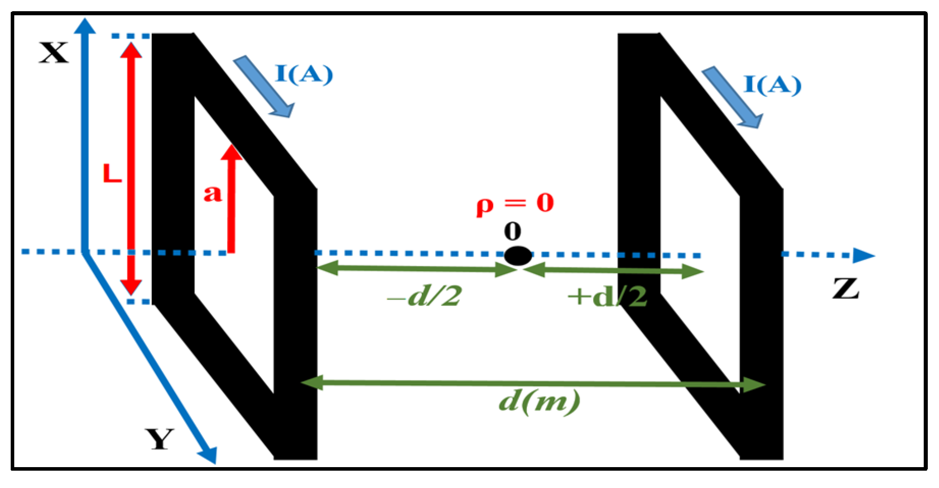
24]. Here, L (in meters) represents the side length of the coil, a (in meters) represents half of L, and
d (in meters) is the distance between the two coils. To generate homogeneous magnetic fields, it is essential to set
d = L. In these scenarios, the magnetic field vector
is described as a function of cylindrical coordinates ρ, φ, and z, where
=
(ρ, φ, z).
According to
Figure 1, for a couple of coils isolated from one another by a separation (d), the law of Biot–Savart is described as [
18,
24,
25].
where
a is coil’s radio (in meters),
μ0 = 4π × 10
−7 is magnetic permeability in vacuum (N
A−2),
I is current (Ampere),
d is the distance between coils (in meters),
N is turns number, and
Bz is magnetic field (Tesla) on
Z axis [
24,
25].
To study the magnetic field in the axis of revolution (Z), Equation (14) was used, according to [
18,
24].
Finally, to study the magnetic field in any radial coordinate (
ρ), Equation (14) is used in proportion to [
18], assuming that
N = 1 in (14) and (15).
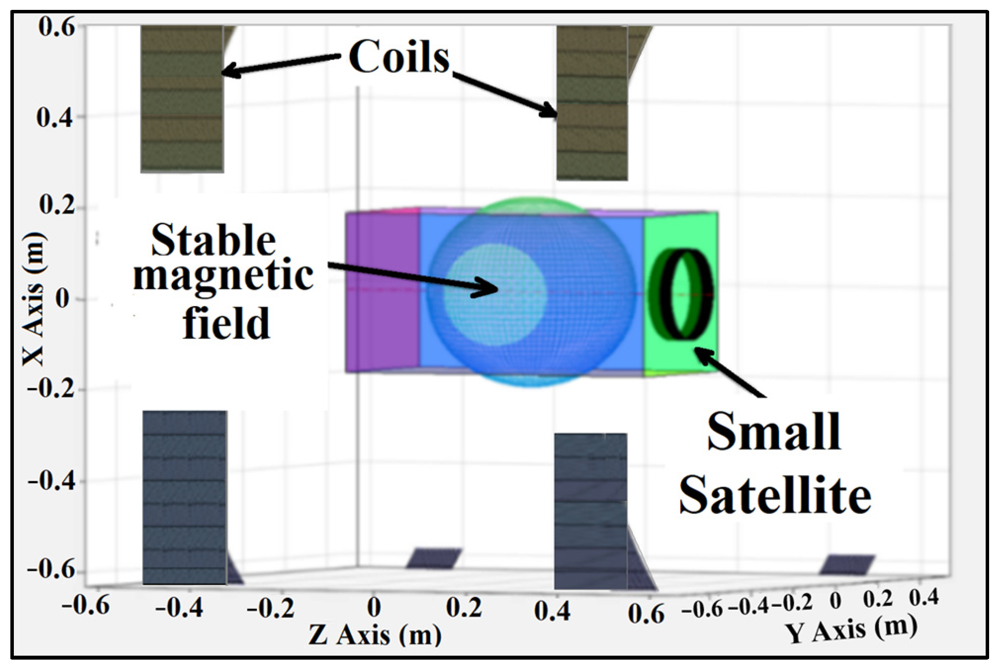
The center of a pair of Helmholtz coils is considered stable within a circumference whose diameter is equal to ½ × distance (d) that separates the two coils [
18,
19], like in
Figure 2; that is, theoretically, at any point within this sphere, the intensity of the magnetic field is considered the same.
On the other hand, in order to evaluate the relative positioning error, the following is known as
where ΔR is the error between the two measurements, R* is the measured value, R is the reference value,
represents the percentage of error obtained in the measurement of each axis of rotation of a body. ΔR is generally known as absolute error and
as permeability [
25,
26,
27].
2.4. IS501NMTB Magnetic Sensor Calibration
When utilizing coils to generate uniform magnetic fields, it becomes essential to calibrate the scale factor error [
28]. The accuracy of the magnetic sensor’s results can be influenced by various factors, necessitating proper calibration of the magnetometers to attain precise measurements [
29]. Generally, there are two primary categories of sources for measurement distortion: magnetic interferences and instrumentation errors [
29]. In this study, the calibration of the magnetic sensor considered both the soft iron error and hard iron error as part of the first category while addressing the non-orthogonal error, scale factor, and bias of sensor offset as elements of the second category.
The soft iron error is produced by ferromagnetic materials within an external magnetic field, such as Earth’s magnetic field [
30]. This error induces variations in the direction and magnitude of the detected magnetic field and can be represented by a mathematical model, such as
where
are the soft iron error that affects each axis.
On the other hand, the hard iron error is induced by a nearby magnetic source with a permanent magnetic field in close proximity to the sensor. This leads to an additional magnetic field that combines with Earth’s magnetic field. As a result, a bias
is introduced in the measured magnetic field [
30]. The representation of this bias can be expressed as
The scale factor
refers to constants of proportionality relating the input to the output [
28] and can be modeled as
Non-orthogonality
, represents the non-alignment of the sensor axes with respect to a main reference system; in this case, the main reference will be determined by the axes that form the coils and can be represented as follows [
29]:
where
represent the directions of the
x,
y,
z axis of sensory in the sensor frame.
The matrix is utilized to correct sensor measurements and account for any misalignment between the sensor axes and the reference axes. By computing the inverse of matrix , the necessary correction factors are obtained to adjust sensor readings and obtain more precise and reliable measurements with respect to the main reference system. This is particularly crucial in applications where precise alignment between the sensors and coils is essential for achieving accurate measurements of the magnetic field.
The sensor offset
, introduces a bias in the output and can be modeled as [
29]:
Finally:
where
represent the calibrated magnetic field and magnetic field measured by the sensor, respectively, as [
29].
3. Main Results
3.1. Orbit Propagation of Satellite and EMF Prediction
To propagate the orbit of a small satellite, a simulation was conducted using the Matlab/Simulink software. The simulation utilized Two-Line Element (TLE) data, as specified in
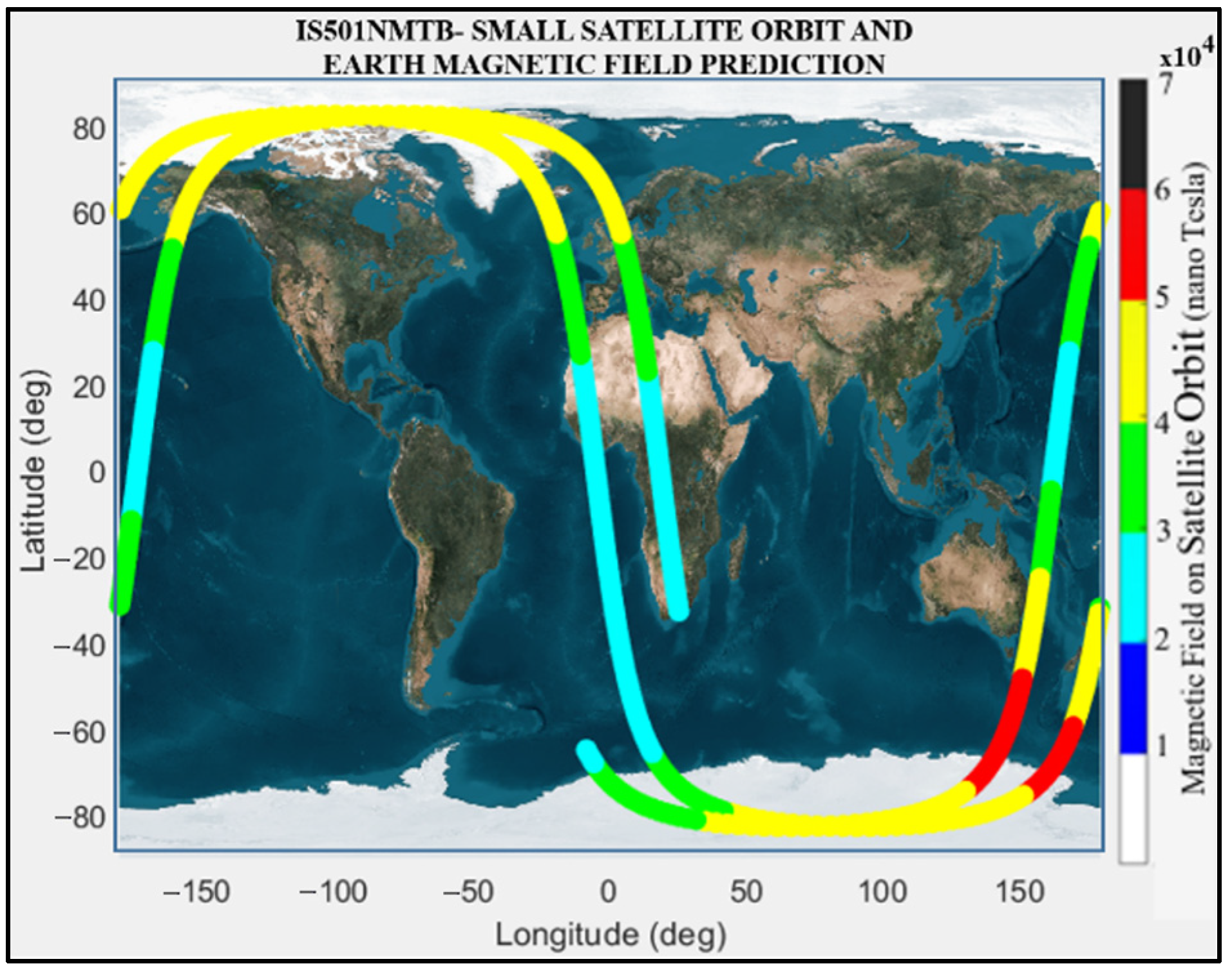
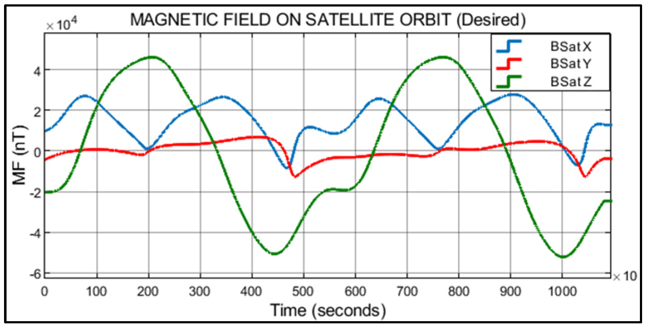
Table 1, and employed the Simplified General Perturbations 4 (SGP4) model as the propagator. Subsequently, by employing the WMM2020 model, the satellite’s magnetic field along its orbit was determined. The orbit propagation of the satellite was simulated for the time interval from 2021 May 17 04:00:00 UTC to 2021 May 17 07:00:00 UTC. The obtained results are presented in
Figure 3 and
Figure 4.
Figure 3 illustrates the outcome of the satellite’s orbit propagation, along with the corresponding measurement of Earth’s magnetic field intensity at each point along the orbit. During a 3 h period, a simulation was conducted in which data were collected for analysis at 10 s intervals. This resulted in a total of 1080 data points obtained from 10,800 samples on each axis. This analysis was conducted to study and validate the results produced by IS501NMTB. In
Figure 4, the temporal evolution of Earth’s magnetic field in the orbit of the small satellite during the studied time period is depicted. The magnetic field values calculated for the
X,
Y, and
Z axes are represented as BSatX, BsatY, and BSatZ, respectively. The graph provides insights into the variations and behavior of Earth’s magnetic field, allowing for an estimation of the specific requirements that the testbed should meet during simulation and assembly.
3.2. IS501NMTB System Architecture Design and Simulation
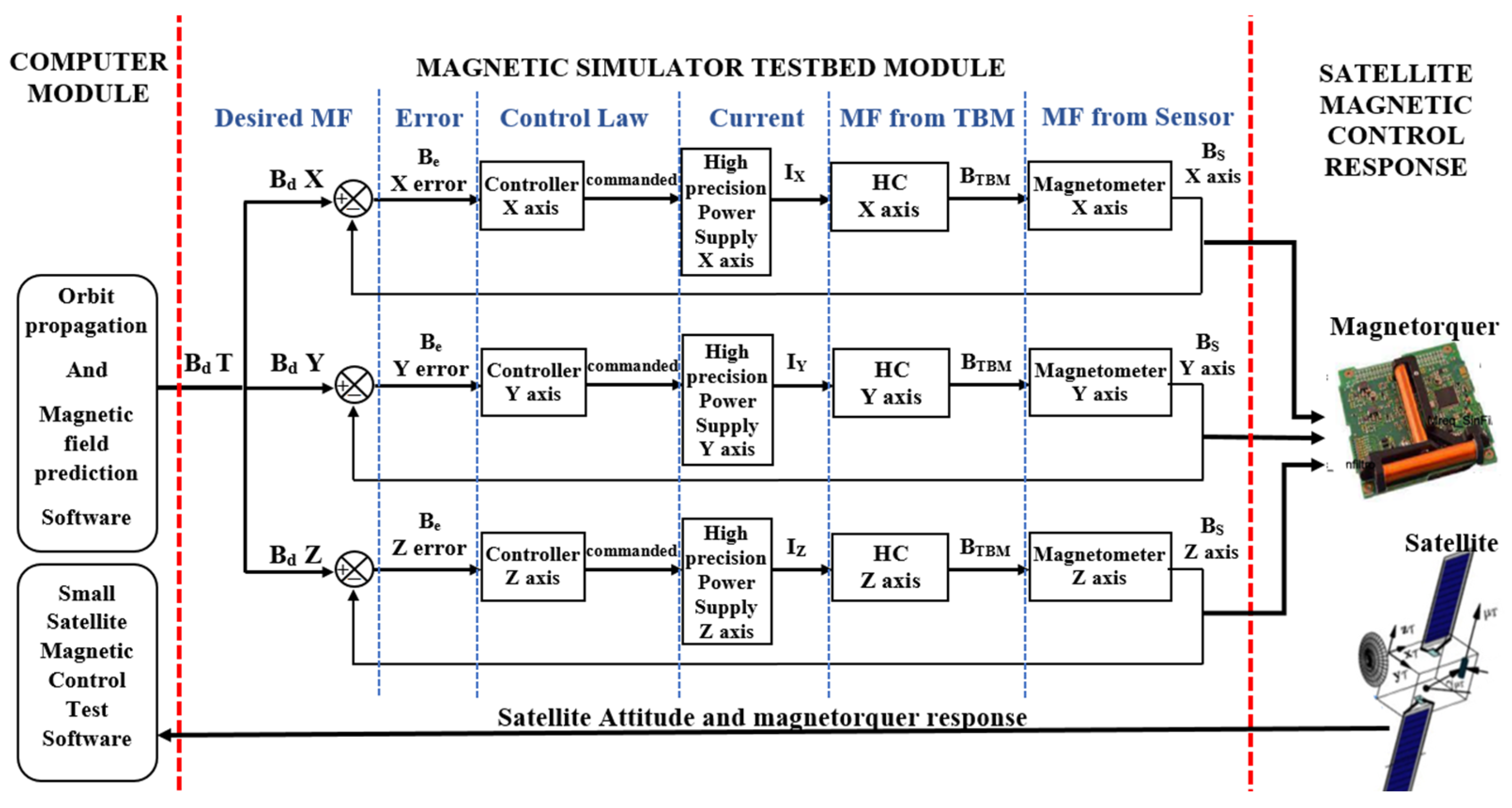
The architectural design of IS501NMTB consists of several key components. These include control module, high-precision DC sources, testbed module (TBM), and software for calibration and manipulation of magnetic fields (MF).
The first component of IS501NMTB architecture is the control computer or module. Its primary function is to facilitate the exchange of information among different components of the testbed. It performs calculations for various purposes, including orbit determination of the small satellite and prediction of Earth’s magnetic fields. The second component comprises devices responsible for injecting variable currents into the coils. These devices allow for the manipulation of magnetic field intensity in each axis. In
Section 3.3 will be illustrated the maximum and minimum voltage and current limits that these devices can generate. These limits are directly related to the resulting magnetic field. The third component consists of coils with specific characteristics outlined in
Table 2. These coils are designed to reproduce the magnetic field to which the satellite will be exposed while in orbit. They play a crucial role in generating the desired magnetic fields for testing purposes. Finally, the architecture includes the main and secondary software components. Their primary function is to calibrate and control the high-precision DC sources. The calibration process aims to neutralize Earth’s natural magnetic field, allowing the coils to accurately reproduce the magnetic fields that will affect the satellite during its orbit.
Figure 5 provides an overview of this process. Overall, the architectural design of IS501NMTB encompasses these components to achieve precise control and reproduction of magnetic fields for testing purposes.
In
Figure 5, B
dT represents the desired magnetic field along the orbit of the satellite; B
dX, B
dY, and B
dZ represent the components of the desired magnetic field in each axis; B
e represents the error between the desired magnetic field and the reproduced magnetic field that can be seen in each axis (
X,
Y,
Z); I
x, I
y, and I
z represent the necessary current that should be generated by the high-precision power supply so that the testbed reproduces the desired magnetic field; HC represents the Helmholtz coils in each axis; B
TBM represents the generated magnetic field by the TBM in each axis; B
S represents the sensed magnetic field by the magnetometer in each axis (
X,
Y,
Z).
Before the construction and assembly of IS501NMTB, extensive simulations were conducted using Ansys Maxwell Software. These simulations aimed to validate the structural design and various configurations of the testbed. The simulations also served to verify the reliability of the parameters specified in
Table 2 and
Table 3, which include the characteristics of the coils and the high-precision power supply required to generate the desired magnetic fields. The results obtained from these simulations helped guide the construction and assembly of IS501NMTB, ensuring its effectiveness in reproducing magnetic fields for testing purposes.
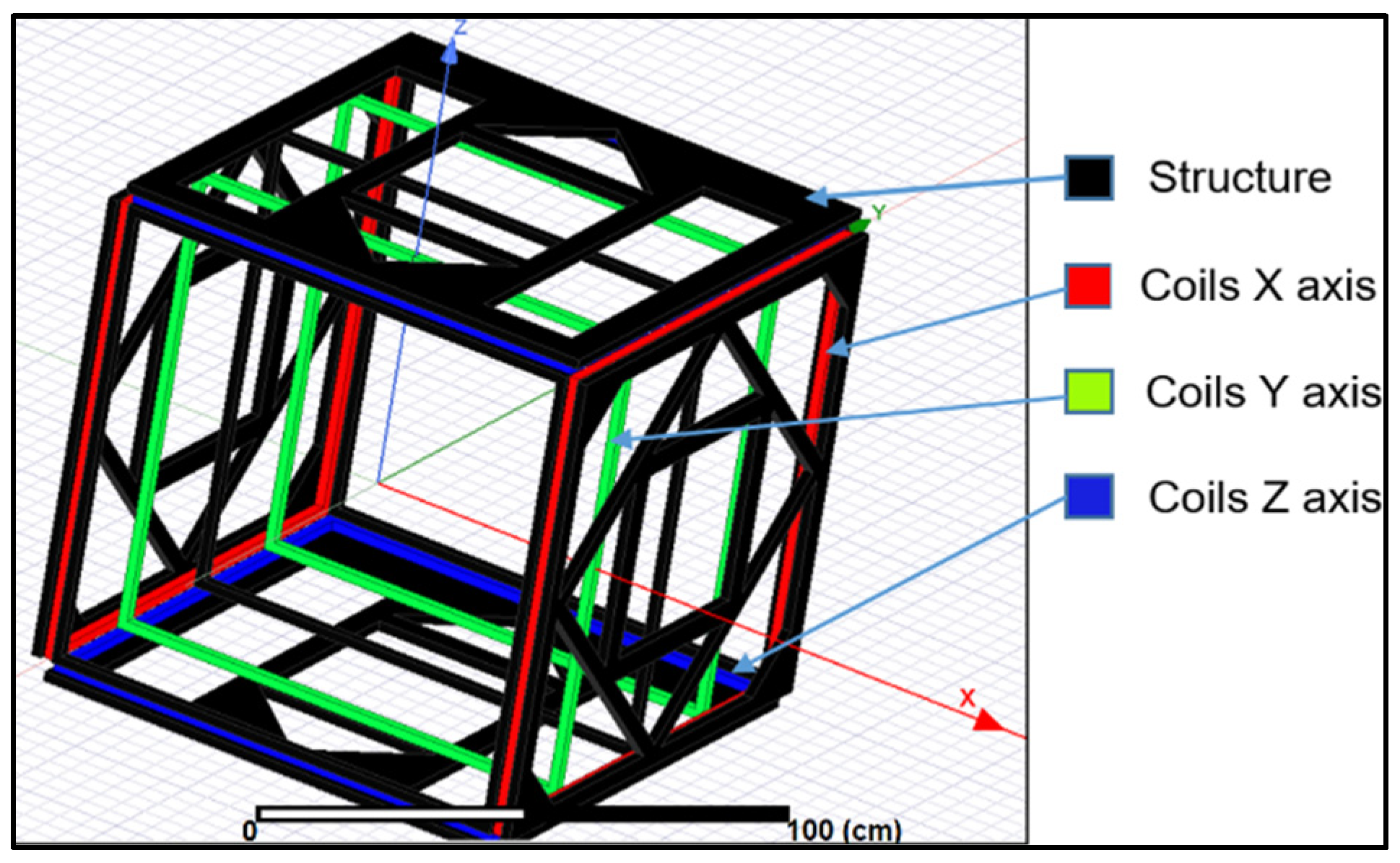
Figure 6 illustrates the final design of the testbed structure, showcasing the arrangement of each coil in their respective axes. The coils responsible for generating the magnetic field along the
X axis are depicted in red, those along the
Y axis in green, and those along the
Z axis in blue. The separation between the axes is adjustable, as specified in
Table 2 and
Table 3, ensuring flexibility in the configuration. In
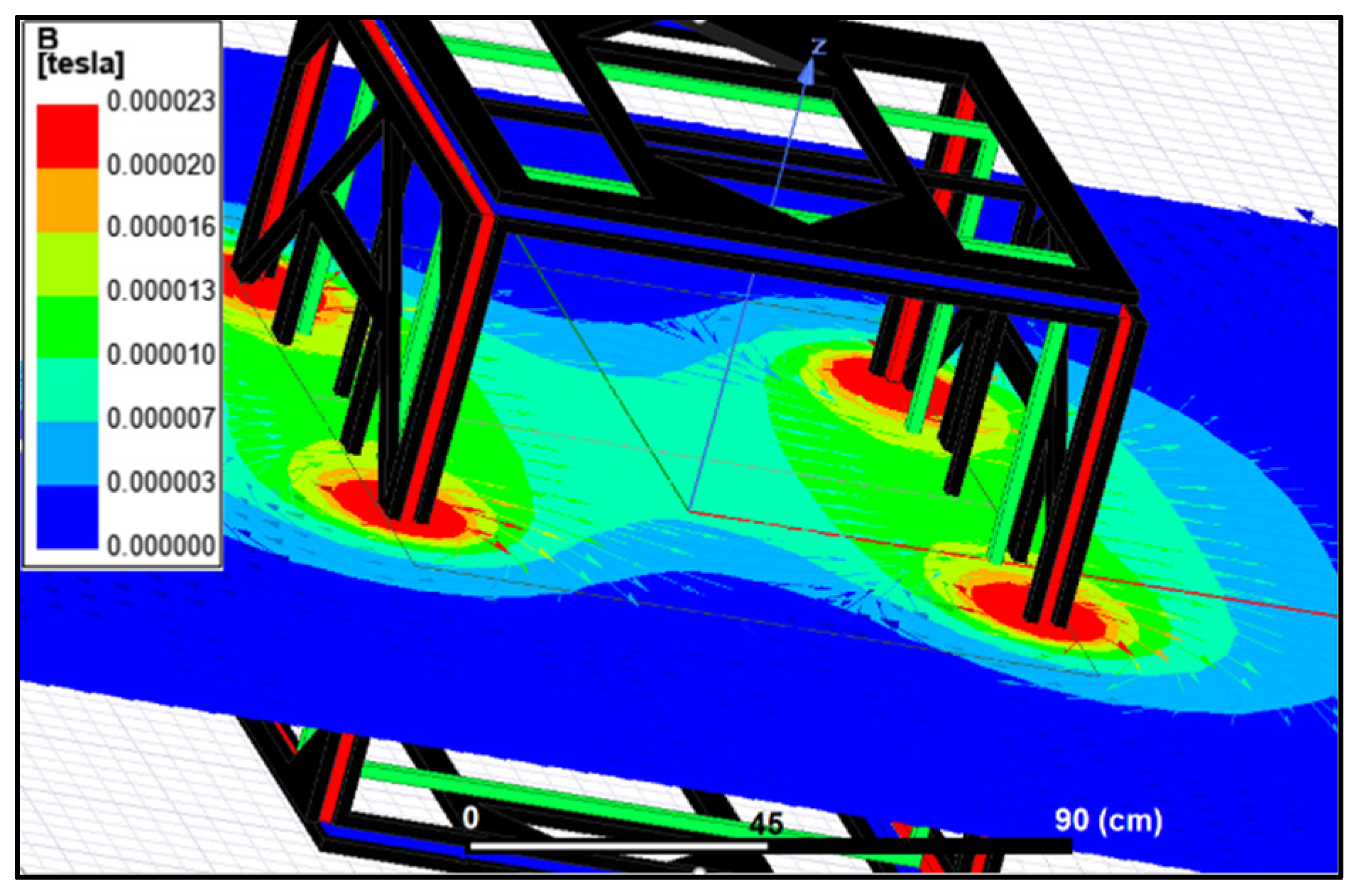
Figure 7, the simulation results along the
Y axis are presented. The magnetic field lines generated in the entire XY plane are visualized, confirming the stability of the magnetic field at the center of the testbed structure. This stability is crucial for accurate and reliable magnetic field reproduction. The specific values of the magnetic field can be further examined in the subsequent figures. These figures provide a comprehensive understanding of the magnetic field distribution and stability within the testbed structure. They validate the effectiveness of the design and the precise control of the magnetic fields generated along different axes, ensuring the testbed’s capability to reproduce the desired magnetic field for the accurate testing of small satellites.
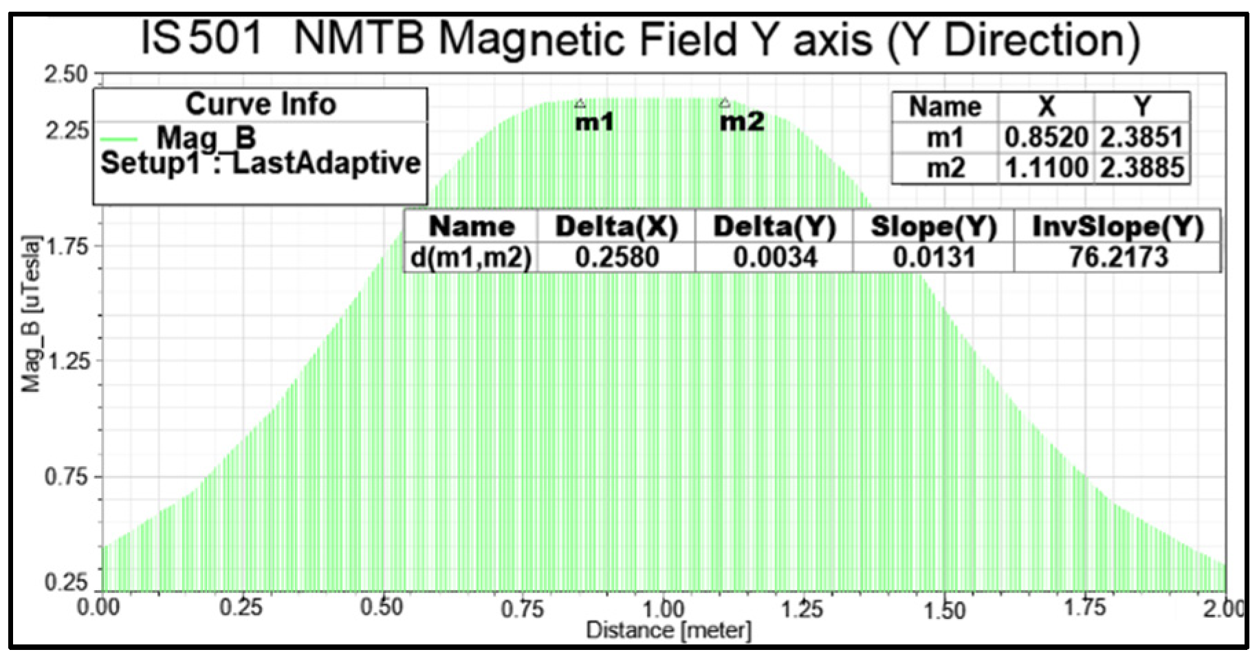
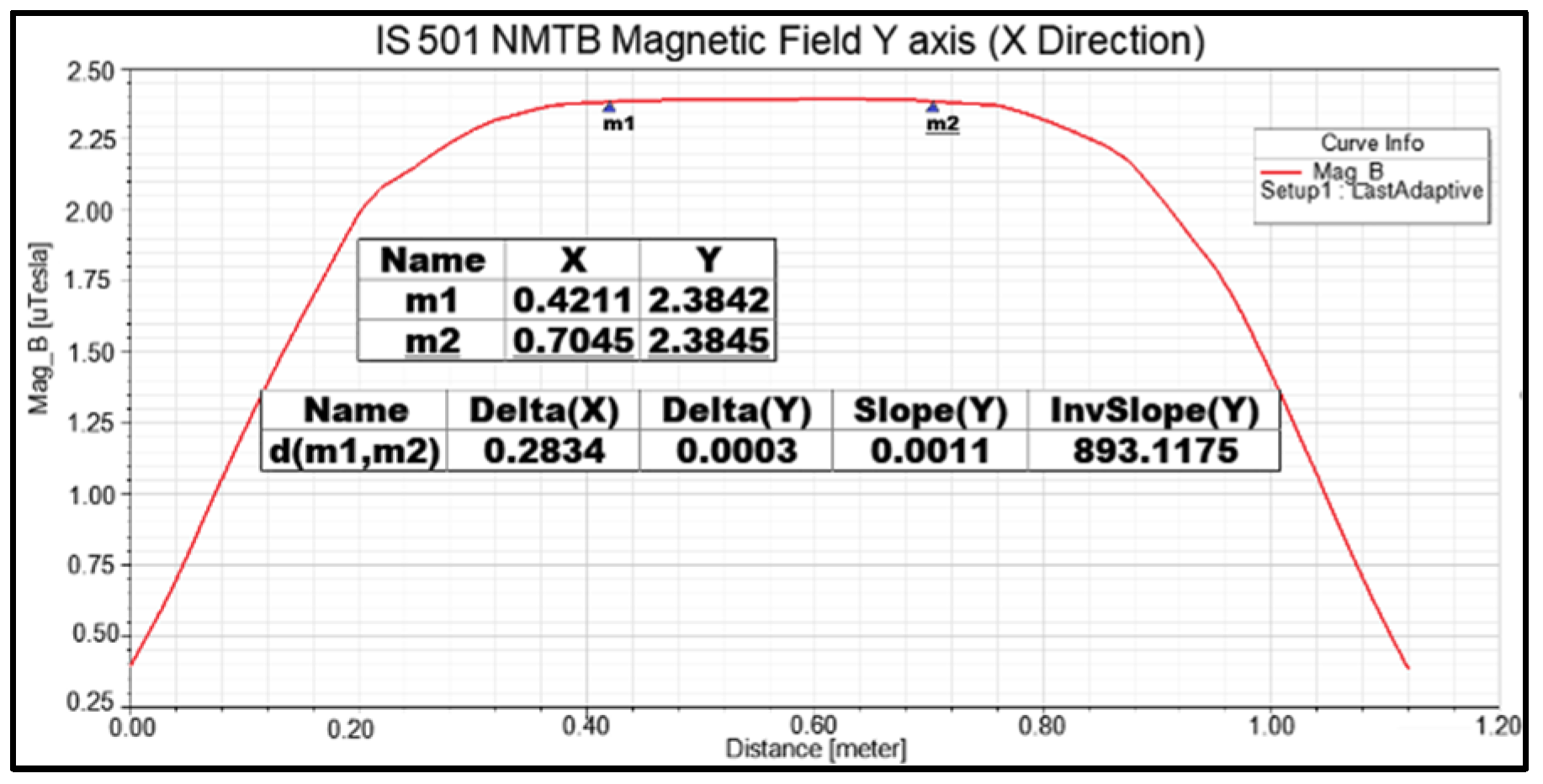
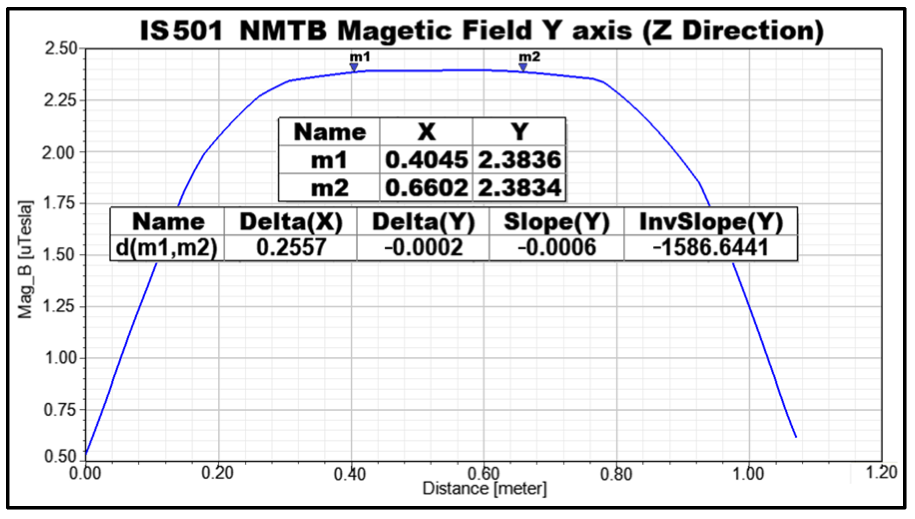
Figure 8,
Figure 9 and
Figure 10 present the precise numerical values obtained from the simulation conducted using the coils of the
Y axis, measured along the
X,
Y, and
Z axes, respectively. These numerical results provide crucial information regarding the magnetic field characteristics. The obtained values demonstrate the following:
Along the X axis, it generated a magnetic field of 2.38 µT, with a length of 28.3 cm.
Along the Y axis, it generated a magnetic field of 2.38 µT, with a length of 25.8 cm.
Along the Z axis, it generated a magnetic field of 2.38 µT, with a length of 25.5 cm.
Based on the simulations and results obtained, it can be concluded that IS501NMTB possesses the capability to generate a stable cubic magnetic field with approximate dimensions of 28 cm × 25 cm × 25 cm. This magnetic field volume is sufficiently large to accommodate satellite testing, specifically for satellites whose magnets have lengths less than or equal to 25 cm. These findings align with the assertions made in [
25,
27], further reinforcing the suitability of IS501NMTB for its intended purpose of conducting magnetic tests on small satellites.
3.3. Assembly and Initial Calibration of IS501NMTB
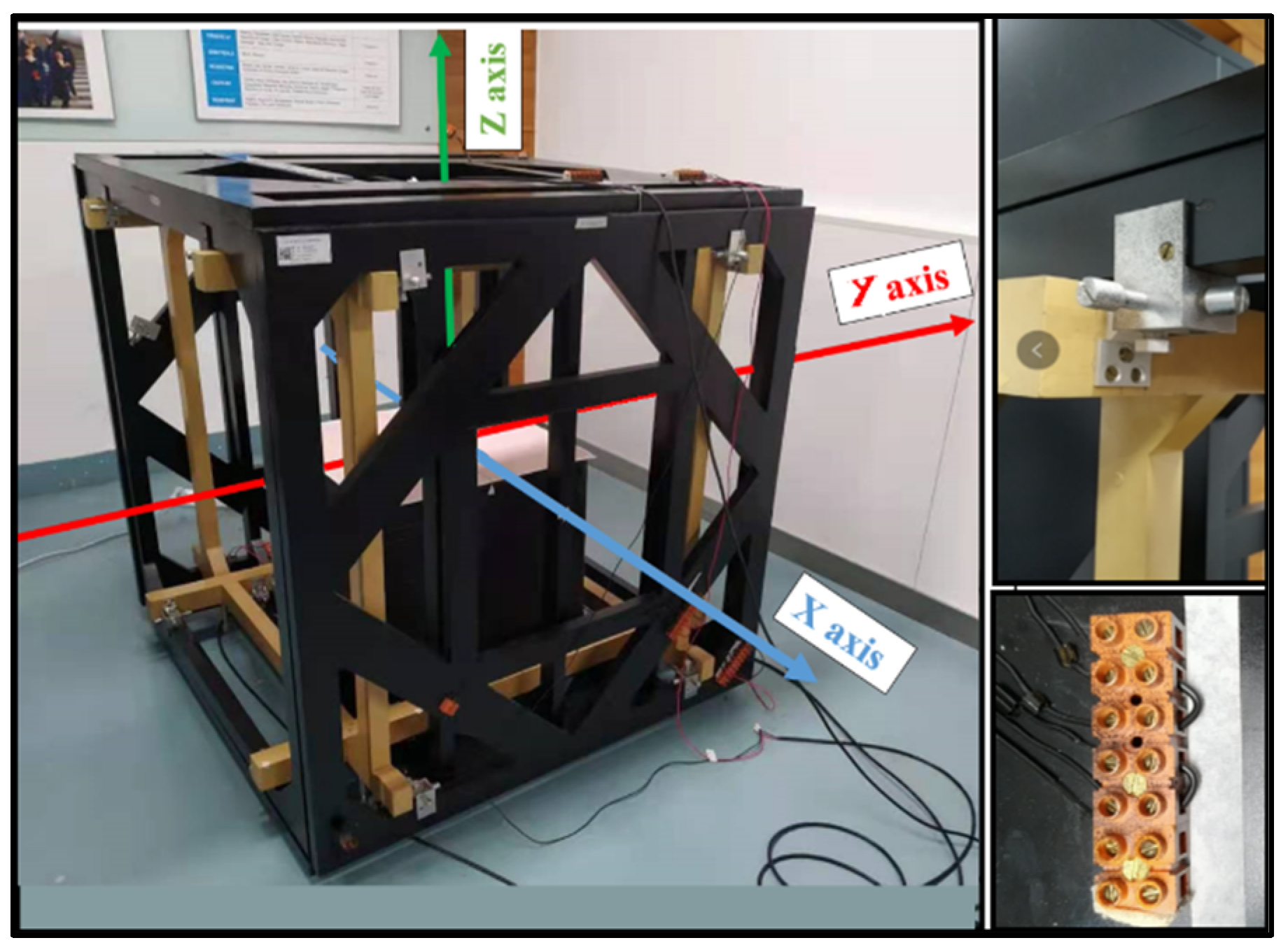
The structure of IS501NMTB, as depicted in
Figure 6, consists of square Helmholtz coils arranged in pairs along each axis of rotation of a small satellite. Its primary purpose is to replicate one of the three components of Earth’s magnetic field. The structure itself is constructed using wood, complemented by small aluminum supports and plastic connectors, as illustrated in
Figure 11. This design ensures a sturdy and reliable framework for the testbed while maintaining the necessary electrical insulation and mechanical stability.
The characteristics of IS501NMTB can be observed in the following
Table 2.
Here in
Table 2, L (in meters) represents the side length of the coil, a (in meters) represents half of L, h (in meters) is the distance between the two coils, and N is the number of turns of the coils.
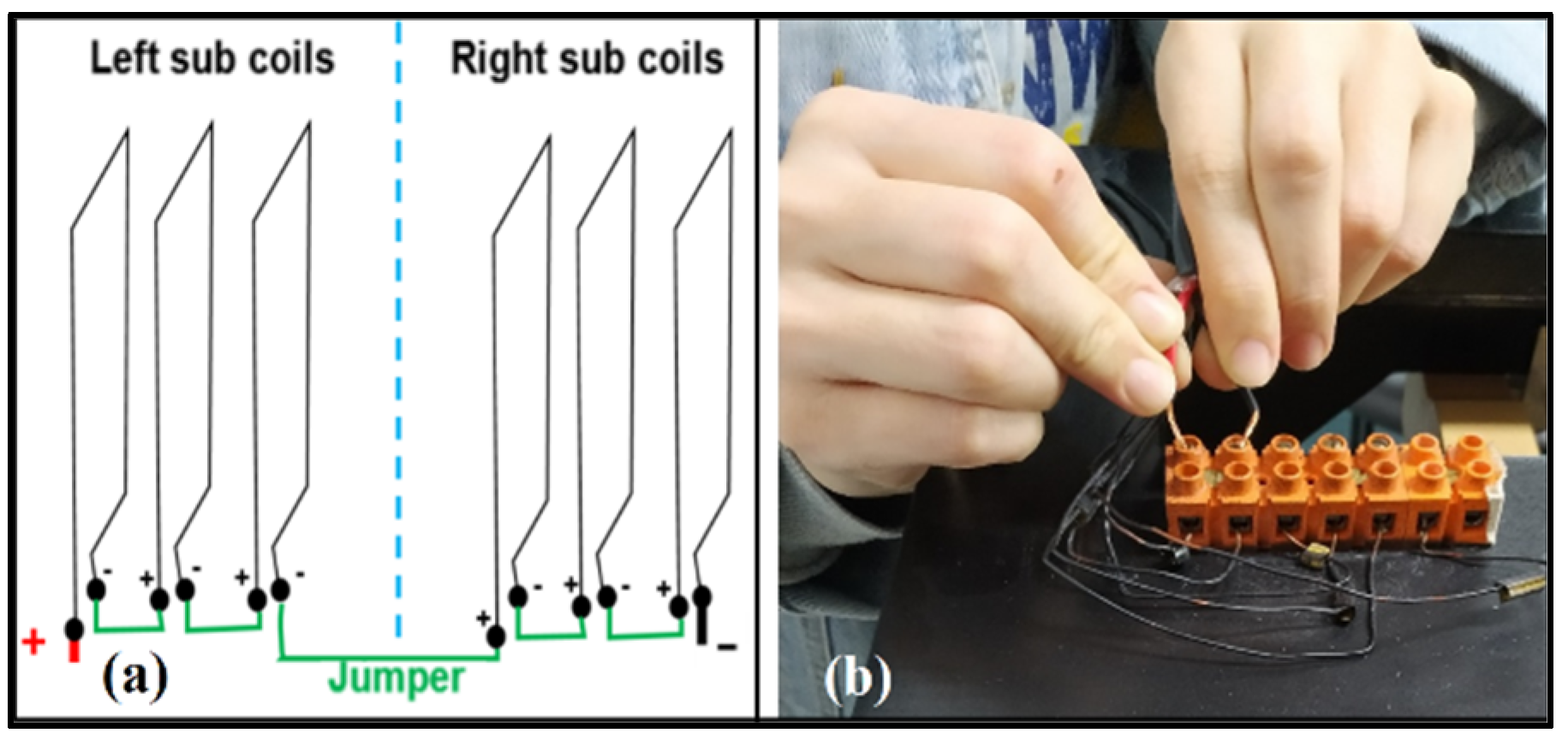
Figure 12 highlights an important aspect of the designed and validated testbed, which is its flexibility. The testbed features an innovative and low-cost jumper port, which enables the adjustment of the number of coils on each axis through connection bridges. This eliminates the need for disassembly of the testbed to add coil turns, thereby increasing the magnetic field while keeping the current unchanged. Furthermore, the lightweight and easily maneuverable structure of the testbed allows for effortless handling, adjustment, and alignment with Earth’s natural magnetic field. The control software facilitates the modification of orbital parameters for simulating Earth’s magnetic field during various satellite orbits. The magnetic model of Earth can be easily updated, and ADC tests can be conducted without time limitations, solely depending on the desired propagated orbit.
Figure 13 provides information regarding the selected high-precision DC sources based on the simulation data. The figure presents details such as voltage and current limits that these sources can generate, which are directly related to the resulting magnetic field.
Additionally, an HSF-100 High-precision Orthogonal Standard Series 3-axis Fluxgate Magnetometer was chosen for the measurement of Earth’s magnetic field components in real time. This magnetometer is capable of accurately sensing and providing data on the magnetic field strength along the three axes.
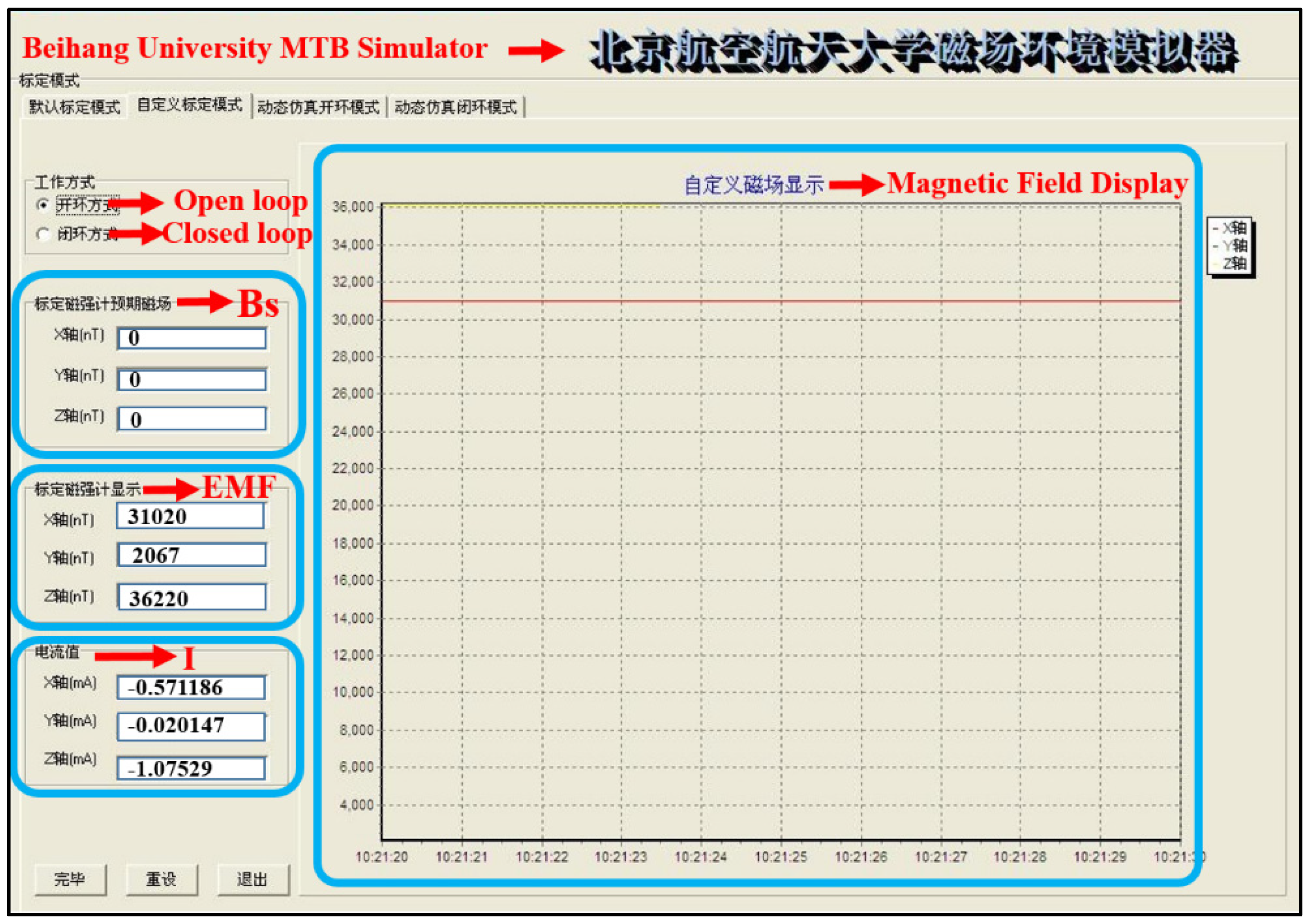
The communication between the “High Precision DC Sources” and the computer controller is established through TCP/IP protocols, enabling data exchange and control commands. Similarly, the computer controller communicates with the three-axis magnetometer using serial communications (COM) ports. Based on this communication setup, the computer controller analyzes the received data and generates appropriate commands to be sent to the “High Precision DC Sources”. To facilitate this control process, a robust Chinese language control software was developed using Delphi 7 software, as depicted in
Figure 14, where B
S, EMF, and I, are variables that were described in
Figure 5 of
Section 3.2. This software provides comprehensive control and calibration functionalities for each component of Earth’s magnetic field. The primary objective of calibration is to nullify the influence of Earth’s magnetic field on measurements, effectively setting it to zero. This process, known as zero calibration, involves calculating the required current (I) and voltage (V) to counteract the sensed magnetic field within IS501NMTB, where V = I × R holds true. As we can see:
where R is the resistance of coils (ohm),
Bd is the desired magnetic field,
Bs is the natural magnetic field measured within the IS50NMTB, and
Bz is the magnetic field generated according to (13). In addition, from (13), the following can be observed:
where
The zero calibration data obtained after the real-time tests can be seen in
Table 3.
The values presented in
Table 3 correspond to the specific current values required by IS501NMTB to effectively nullify Earth’s natural magnetic field. It was observed that, for the
Z axis, a current of −1.082 A was necessary for neutralization. However, during the actual ADC tests, this current is not constant but rather dynamic, varying over time according to the satellite’s orbit. This dynamic behavior prevents overheating of the electrical lines. It is worth noting that the design of the testbed ensures its capability to withstand higher current intensities without issues. Similar observations were conducted for the
X and
Y axes, with required current values of −0.571 A and −0.041 A, respectively.
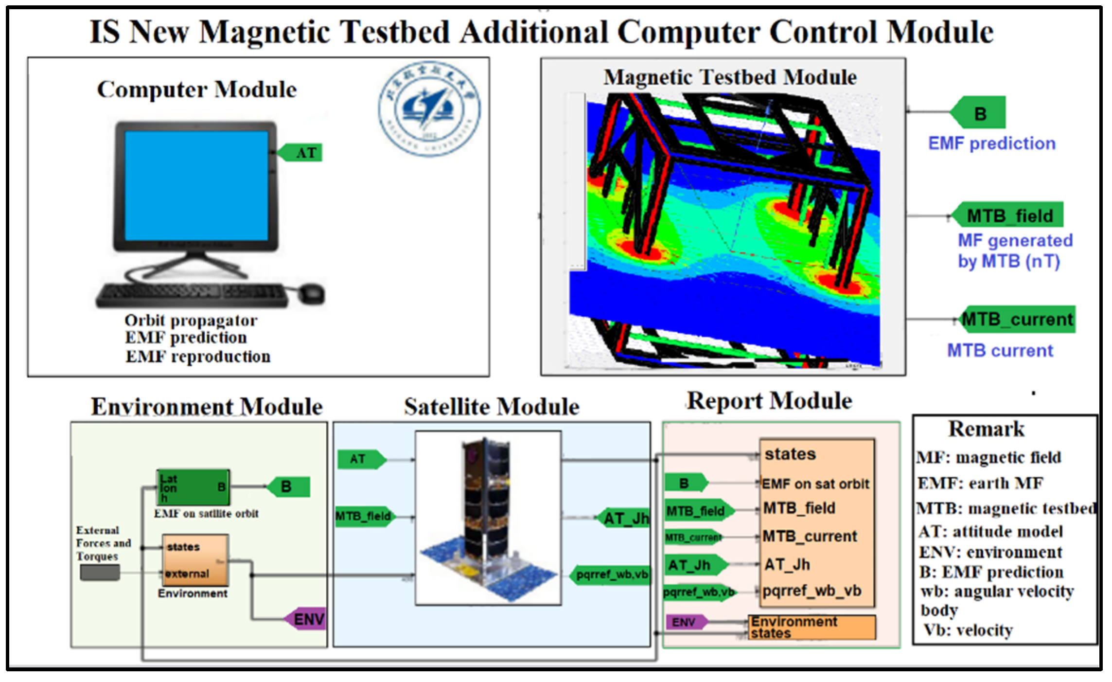
In addition to the main control software, developed in Delphi 7 software, additional software was developed as a complement, utilizing Matlab/Simulink, as depicted in
Figure 15. This complementary software serves several purposes. Firstly, it facilitates the calculation of the orbit for any small satellite, enabling the prediction of Earth’s magnetic field influence on the satellite along its orbit. Furthermore, it allows the software to send commands to IS501NMTB in order to reproduce the calculated EMF. By utilizing the results generated by this complementary software, a comprehensive study on small-satellite magnetic control can be conducted.
3.4. Calibration of IS501NMTB
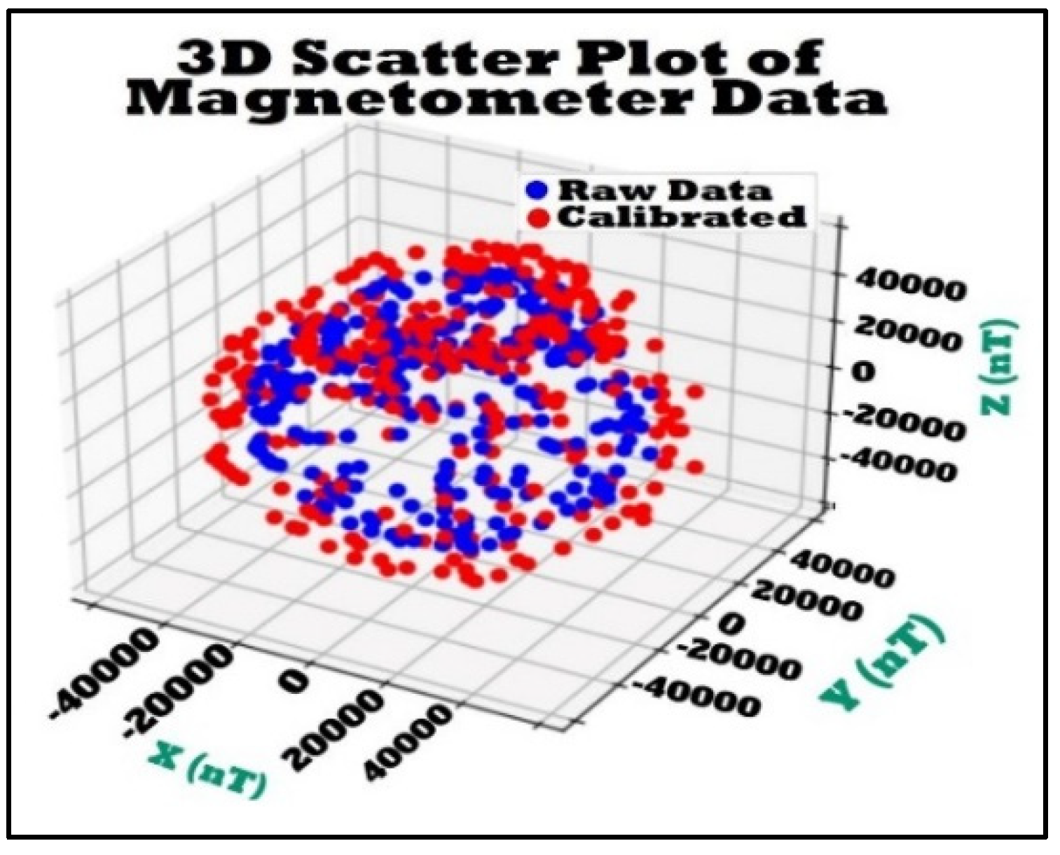
In order to enhance the precision of the magnetic field measurements generated by IS501NMTB, the magnetometer underwent calibration. This involved collecting data from Earth’s magnetic field at the center coordinates of IS501NMTB, as depicted in
Figure 11. The sensor was positioned at the center and rotated randomly around the origin of the three axes. Simultaneously, a program developed in Matlab recorded the measured data, resulting in a collection of magnetic information points surrounding the sensor, forming a “cloud” of data. A total of 500 data points were stored during this calibration process.
Using the collected “Data not calibrated” cloud and the magnetic field measurement of 54,813.1 nT obtained from [
17] at the location where IS501NMTB was assembled (as specified in
Table 1), it was possible to generate the
matrix, from
A matrix, and
vector, after the calibration process, following Equations (25) and (26), respectively. The resulting values are as follows:
Using Equation (24), it was possible to obtain the calibrated data for each axis from the “Non-calibrated data,” as shown in
Figure 16. The parameters
and
were utilized within the “Complementary Control Software” (
Figure 15) to perform real-time calibration for all the magnetic field measurements reproduced by IS501NMTB. These measurements represent magnetic fields that are identical to those recorded in the orbit of the small satellite, as specified in
Table 1.
In
Figure 16, the results obtained during the calibration of the IS501NMTB magnetic sensor are displayed. The blue color represents the cloud of non-calibrated data, while the red color represents the data transferred to the center of the coordinate axis, indicating the calibrated data.
3.5. Results Verification
For data collection and processing, the information presented in
Table 1 was utilized as the input data. These data were inputted into both the “Principal Control Software” of IS501NMTB (refer to
Figure 14) and the “Additional Control Software” (refer to
Figure 15). This integration enabled the real-time physical control of IS501NMTB, allowing for the accurate reproduction of Earth’s magnetic field throughout the satellite’s orbit (refer to
Figure 3), precisely at the center of its structure. In order to validate these results, a comprehensive analysis was conducted on a total of 1080 magnetic field samples acquired from the satellite’s orbit. From this dataset, seven (07) samples were meticulously selected and presented in this publication, showcasing their complete consistency with the overall set of analyzed magnetic fields. The real-time data obtained can be observed in
Table 4.
Table 4 displays the obtained results for the specific latitude, longitude, height coordinates, as well as the predicted Earth’s magnetic field values for the small satellite. Additionally, it showcases the reproduced Earth’s magnetic field values by IS501NMTB.
Information from
Table 4 was utilized to generate
Table 5, which provides insights into the accuracy and reliability of the obtained data.
Table 5 presents a subset of the results obtained during the real tests conducted along the orbit of the small satellite. The table includes the desired EMF, the magnetic field reproduced by the testbed, and the corresponding percentage of accuracy of the reproduced magnetic field.
Table 6 provides the overall average accuracy and error generated by the testbed during the real tests. It demonstrates that, after the calibration process, the magnetic fields reproduced by IS501NMTB exhibit an accuracy greater than 99.893%, 99.895%, and 99.889% on the
X,
Y, and
Z axes, respectively. The corresponding errors are 0.107%, 0.105%, and 0.111% for the respective axes. These calculations were based on the analysis of 1080 verified magnetic field samples obtained along the orbit of the small satellite.
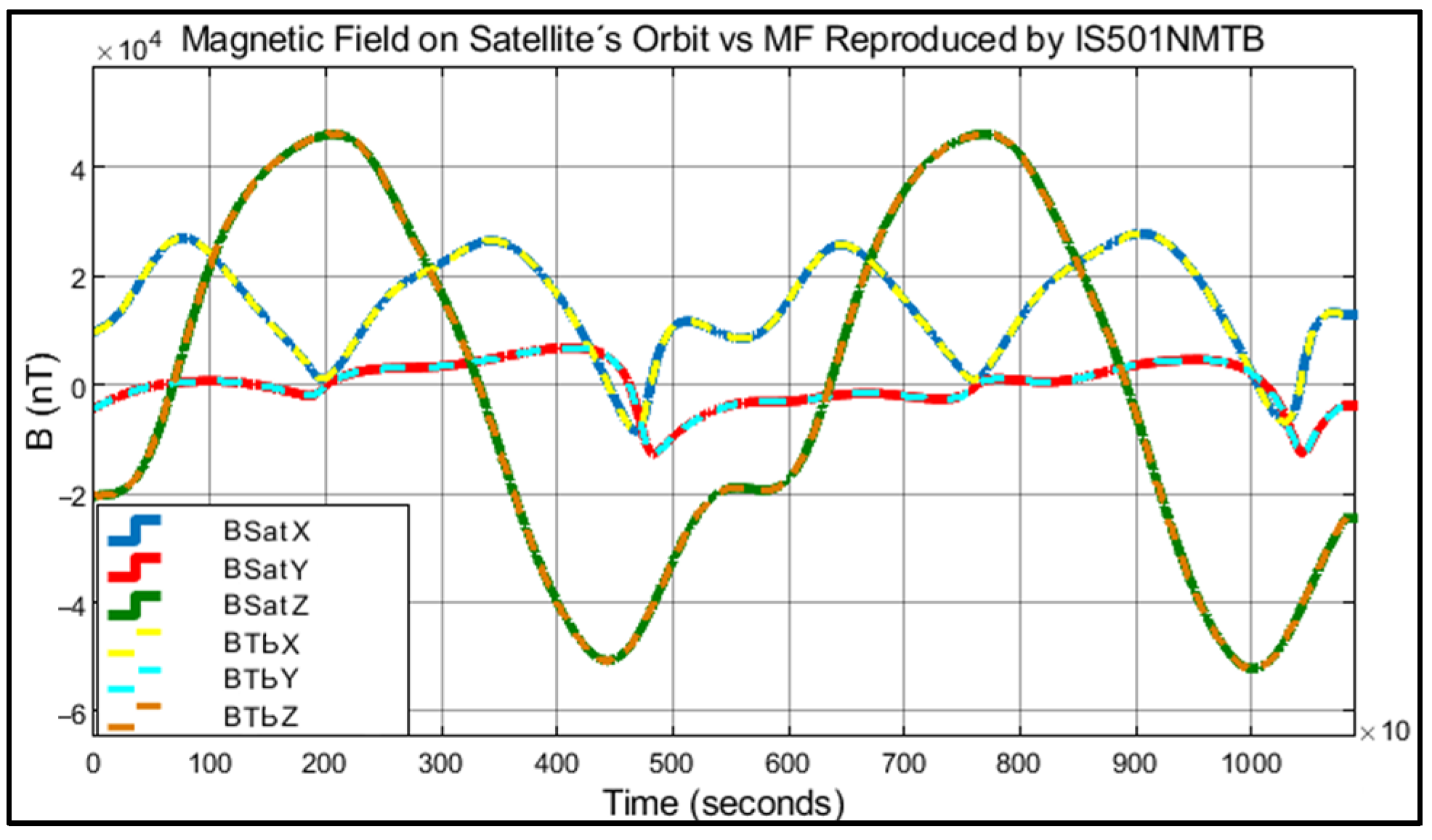
The total of the verified results can be seen graphically in the following figures:
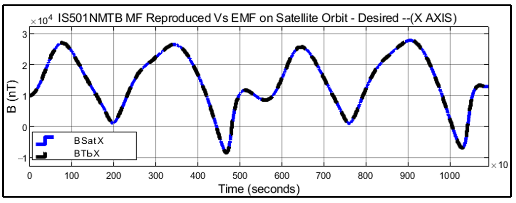
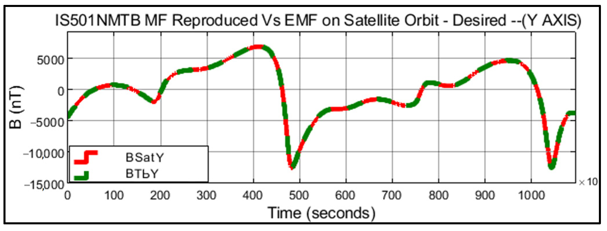
Figure 17 displays the graphical representation of all the results obtained during the data generation and verification process. The magnetic fields BSatX, BSatY, and BSatZ represent the components of Earth’s magnetic field in the orbit of the small satellite. On the other hand, BTbX, BTbY, and BTbZ correspond to the magnetic fields generated by IS501NMTB in each of its respective axes in the laboratory.
Figure 18 shows in black color the X component of the magnetic field generated in real time by IS501NMTB and the magnetic field in the orbit of the small satellite in blue color.
Figure 19 shows in black color the Y component of the magnetic field generated in real time by IS501NMTB and the magnetic field in the orbit of the small satellite in red color.
Figure 20 shows in black color the Z component of the magnetic field generated in real time by IS501NMTB and the magnetic field in the orbit of the small satellite in red color.
Figure 18,
Figure 19 and
Figure 20 present the graphical representation of the data from
Table 4 throughout the entire evaluated period, as specified in
Table 1. These figures illustrate the reliability and capability of IS501NMTB to accurately reproduce magnetic fields along the orbit of small satellites.
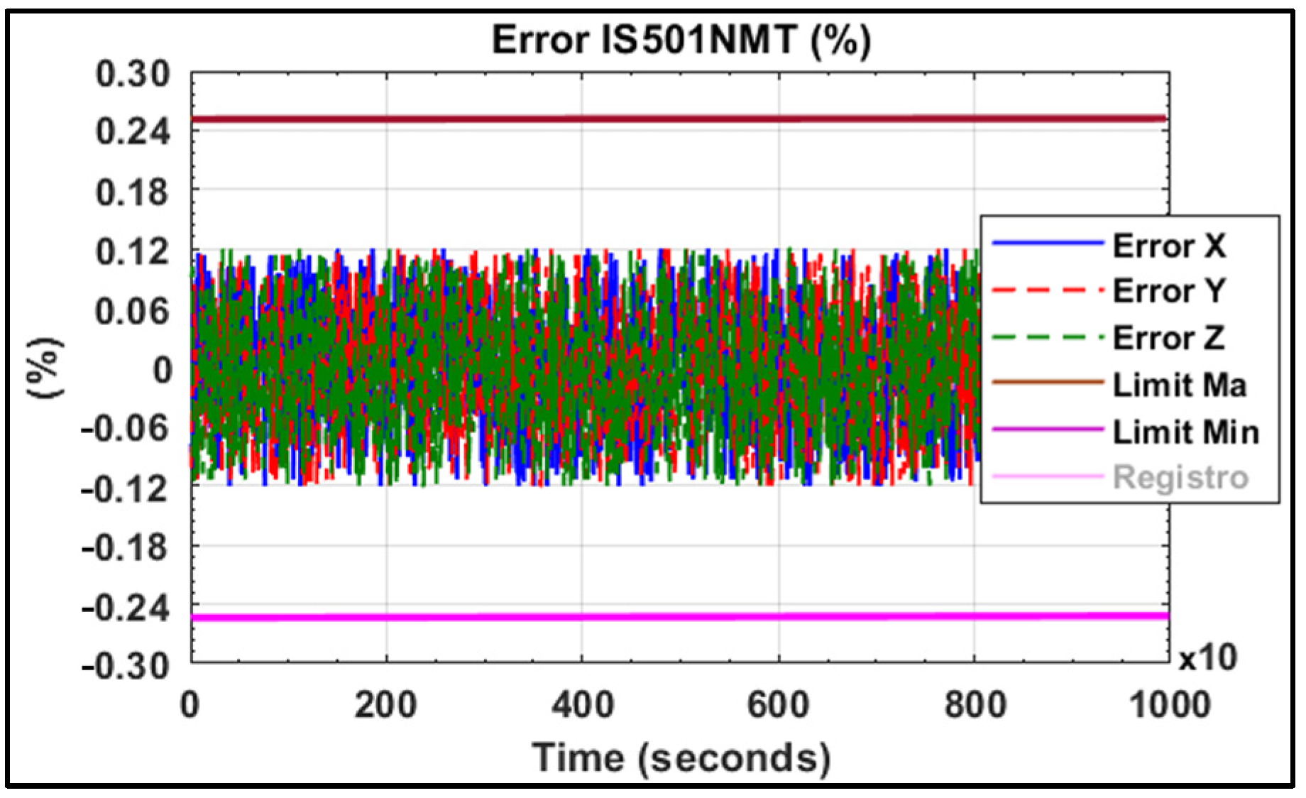
In
Figure 21, the errors obtained by IS501NMTB during the reproduction of the magnetic fields affecting the small satellite throughout its orbit are depicted. It can be observed that the error remained consistently below 0.111% for each axis, relative to each component of Earth’s magnetic field, throughout the entire orbital period studied.
Table 7 presents the results obtained during the verification of the magnetic field deviation generated by the testbed along the
X and
Y axes, as expressed in Equation (18). The values are provided in terms of the measured value along the axis (
r*) and the reference value measured at the center of the axis (
r). The deviation percentage (e*) can range from 0% to 100%, where 0% indicates no deviation and 100% indicates maximum deviation. According to these results, the testbed demonstrates the ability to generate a stable and homogeneous magnetic field with a deviation of approximately 0.10% along the axis, within a diameter of approximately 25 cm. This finding aligns with the findings expressed in [
18,
19] regarding the size of the homogeneous magnetic area achievable with Helmholtz coils. The currents injected in the
X and
Y axes to obtain the results in
Table 6 were −0.08 A and −0.0573 A, respectively.
These results were obtained before the calibration of the system, as described in
Section 2.4. The calibration process involved the elimination of both internal and external magnetic interferences from the system. It also involved adjusting the current values through feedback PID controls on each axis, as depicted in
Figure 5. This allowed for constant monitoring of the magnetic field generated at the center of IS501NMTB. Furthermore, proper physical alignment perpendicular to the three axes was necessary to ensure that the magnetic field generated by one axis did not affect the other axes. In other words, the magnetic component of one axis on the other axes was maintained at zero.
3.6. Comparison with Other Research Work
The following
Table 8 provides a comprehensive comparison of results obtained from various research studies related to the generation of stable magnetic fields capable of reproducing Earth’s magnetic field using Helmholtz coils. Several key aspects relevant to small-satellite control testing are evaluated, including the adequacy of the testbed size, presence of dynamic orbital propagation software, magnetic field generation error, ease of coil turns variation, proper calibration, maximum generated currents, ease of updating Earth’s magnetic model, and the small satellite’s orbital parameter updates. Each research work is referenced accordingly. These comparative data allow for the evaluation and selection of the most suitable approach for magnetic field generation in the context of small-satellite magnetic control testing. The sixth entry in
Table 8 corresponds to the results obtained in this research.
The results of various investigations on small-satellite magnetic control testing, including the ongoing research, are summarized in
Table 8. The present study has demonstrated significant improvements compared to previous works, establishing the proposed design as superior in generating reliable and precise magnetic fields. These advancements enable more rigorous testing protocols and precise measurements in small-satellite magnetic control. The outcomes of this study validate the efficacy and exceptional quality of the proposed design, setting it apart from previous methodologies.
In the context of vector algebra, the dot product of two vectors, A and B, is expressed as A · B = ∣A∣ ∣B∣ cos(θ), where ∣A∣ and ∣B∣ represent the magnitudes of vectors A and B, and θ is the angle between them. This equation underscores the importance of the angle between vectors in determining the magnitude of their dot product. When considering the alignment of orthogonal axes in a magnetic testbed, minimizing the angle between the axes becomes crucial to reduce the influence of one magnetic field on another. By aligning the axes orthogonally, angle θ approaches 90 degrees, resulting in cos(θ) = 0 and effectively eliminating cross-axis interference. Therefore, careful attention to achieving proper alignment ensures accurate measurement and control of magnetic fields along each orthogonal axis, enhancing the reliability and precision of magnetic testbed experiments and subsequent data analysis.
The alignment of orthogonal axes (X, Y, and Z) in a magnetic testbed is crucial to prevent interference between magnetic fields generated along different axes. Proper alignment minimizes cross-axis contamination and ensures the independence of each magnetic field component. This alignment is particularly important in applications requiring accurate magnetic field measurements, such as small-satellite magnetic control testing. Deviations from orthogonal alignment can lead to inaccurate readings and compromised results as one axis’s magnetic field may inadvertently affect measurements along other axes. Therefore, meticulous attention should be afforded to aligning the testbed’s axes accurately, utilizing established techniques and advanced calibration methods to mitigate crosstalk and interference. Proper alignment guarantees the reliability, accuracy, and validity of magnetic field measurements, facilitating robust analysis in various scientific and engineering disciplines.
4. Discussion
The high failure rate of approximately 25% among small satellites placed in orbit can be attributed to the lack of comprehensive laboratory testing prior to launch, often due to the use of magnetic testbeds that do not guarantee the desired levels of accuracy and reliability. However, this research has successfully addressed this issue by designing, assembling, testing, and verifying a flexible and reliable magnetic testbed capable of achieving accuracy levels of at least 99.89%. This testbed enables thorough testing of the attitude and control subsystems of small satellites, ultimately reducing the failure rate of such satellites. Additionally, it allows for the qualification that the magnetorquers, already integrated into the satellite, have the capability to ensure accurate orientation of the satellite throughout its entire orbit. The simulations and experimental tests conducted in this research have highlighted the importance of a rigorous and meticulous process for assembling, adjusting, and calibrating the testbed in order to achieve the desired levels of accuracy and reliability. The testbed’s flexible design and the control software have facilitated easy updates of Earth’s magnetic model and adjustments in satellite parameters and orbital characteristics.
As a result, the testbed can accurately replicate Earth’s magnetic fields in real time, ensuring precise orbital propagation of satellites in low Earth orbit within the desired time interval. As a method to measure the behavior of the satellite’s attitude system, with its integrated magnetorquers, when exposed to the magnetic field within the testbed, data reading is performed. These data include the current injected into the magnetorquers on each axis and the satellite’s orientation values on each axis, obtained from the received telemetry of the satellite. The objective of this reading is to certify the proper functioning of the attitude system.
In summary, this research presents a flexible and highly accurate testbed model that significantly improves the reliability and performance of small satellites. It emphasizes the crucial role of proper assembly, adjustment, and calibration processes in achieving the desired levels of accuracy and reliability. With its real-time replication of Earth’s magnetic fields and its high degree of flexibility, the testbed serves as a valuable tool for the development and testing of small-satellite systems.
The research findings highlight several important aspects regarding the configuration and calibration of the testbed for improved accuracy and reliability. It was observed that the initial technical configuration parameters of the testbed should be adjusted based on values obtained from experimental tests rather than relying solely on theoretical values. This is due to variations in resistance within each coil caused by factors such as impurities and manufacturing defects in the conductive material. By conducting experimental tests, the actual resistance values of the entire conductor line in each axis, including the power sources, can be determined. Furthermore, it was crucial to carefully install each axis of the testbed in an orthogonal manner to prevent the magnetic field generated in one axis from affecting the other two axes. This ensured that the magnetic components of one axis had no impact on the measurements of the other axes, maintaining their independence and accuracy. To enhance the accuracy and reliability of the testbed’s results, a meticulous “magnetic calibration” process was conducted. This involved taking into account various external factors, such as the natural magnetic field of Earth at the installation location, which was automatically sensed and updated before each test.
Additionally, the calibration of the magnetic sensor considered factors like soft iron error, hard iron error, bias, and non-orthogonality. Even in the case of high-precision sensors that are pre-calibrated by the factory, external factors close to the testbed, including electromagnetic sources and magnetic or magnetizable structures, can still impact sensor measurements. Therefore, a recalibration of the magnetic sensor was necessary to account for these factors and improve the accuracy of the results. By addressing these aspects, including adjusting technical parameters based on experimental tests, ensuring orthogonal installation, and conducting thorough magnetic calibration, the research has significantly improved the accuracy and reliability of the testbed’s measurements and results.
5. Conclusions
In this research work, we focused on the design, simulation, and verification of a magnetic testbed specifically tailored for conducting tests on the Attitude Determination and Control (ADC) systems of small satellites equipped with magnetic actuators. Throughout the entire process, meticulous attention was afforded to the data collection and calibration procedures to ensure the obtained results closely aligned with the simulated outcomes. Furthermore, to guarantee the desired levels of accuracy, stability, and reliability in the magnetic fields generated by IS501NMTB, various external factors were taken into consideration, including Earth’s magnetic field at the installation site. This comprehensive calibration process also accounted for potential sources of error, such as soft iron error, hard iron error, bias, and non-orthogonality.
Upon completing the comprehensive process encompassing analysis, design, simulation, assembly, and verification of IS501NMTB, it has been established that the chosen design possesses the necessary technical characteristics to accurately reproduce the magnetic fields encountered within the satellite’s orbit. The achieved accuracy surpasses 99.889%, ensuring an error margin below 0.111% for all three axes (X, Y, and Z) throughout the studied 3 h satellite orbit. With a sampling interval of 10 s and a total of 1080 data points obtained from a universe of 10,800 samples simulated on each axis, a grand total of 3240 magnetic data points were meticulously analyzed for all three axes (X, Y, and Z). The remarkable outcome derived from this extensive analysis showcases that the errors consistently remained below the 0.111% threshold throughout the entire study period.
Furthermore, a notable accomplishment was the attainment of a mere 0.10% deviation within a magnetic field spanning approximately 25 cm in diameter. This level of precision suffices for testing satellites ranging from 1 unit CubeSat to compact microsatellites equipped with magnetorquers not exceeding 20 cm in length. It is crucial to emphasize that it is not imperative for the entire satellite structure to reside entirely within the homogeneous magnetic field. Rather, the pivotal concern lies in ensuring that the magnetorquer itself operates within the confines of this homogeneous field.
The comprehensive design of the testbed developed in this research not only exhibits flexibility but also guarantees the generation of magnetic fields that are both reliable and precise. With the aid of this tool and based on the attained results, it becomes feasible to conduct more accurate and reliable ADC tests. Consequently, this enhanced testing capability will contribute to elevating the success rate of small satellites upon their deployment into orbit.
Author Contributions
Conceptualization, X.W. and J.U.; methodology, J.U. and M.G.; software, J.U. and G.C.; validation, J.U.; formal analysis, G.C.; investigation, M.G.; resources, X.W.; writing—original draft, J.U., G.C. and M.G.; writing—review and editing, X.W., J.U. and M.G.; visualization, J.U., G.C. and M.G.; supervision, X.W.; project administration, J.U. and X.W.; funding acquisition, X.W. All authors have read and agreed to the published version of the manuscript.
Funding
This research was funded by China Association for Science and Technology (CAST) Program of International Collaboration Platform for Science and Technology Organizations in Belt and Road Countries, grant number 2021ZZGJB071531.
Institutional Review Board Statement
Not applicable.
Informed Consent Statement
Not applicable.
Data Availability Statement
Not applicable.
Acknowledgments
The authors would like to thank the UN Regional Centre for Space Science and Technology Education in Asia and the Pacific (UN RCSSTEAP), National Space Science Center (NSSC)-China Association for Science and Technology (CAST), and Asia-Pacific Space Cooperation Organization (APSCO) for all the technical, academic, and scientific support during the development and consolidation of this research.
Conflicts of Interest
The authors declare no conflict of interest.
References
- Bahu, A.; Modenini, D. On-ground experimental verification of magnetic attitude control for nanosatellites. In Proceedings of the IEEE 8th International Workshop on Metrology for AeroSpace (MetroAeroSpace), Naples, Italy, 23–25 June 2021; pp. 568–573. [Google Scholar] [CrossRef]
- Villela, T.; Costa, C.A.; Brandão, A.M.; Bueno, F.T.; Leonardi, R. Towards the Thousandth CubeSat: A Statistical Overview. Int. J. Aerosp. Eng. 2019, 2019, 5063145. [Google Scholar] [CrossRef]
- Farissi, M.S.; Carletta, S.; Nascetti, A.; Teofilatto, P. Implementation and Hardware-In-The-Loop Simulation of a Magnetic Detumbling and Pointing Control Based on Three-Axis Magnetometer Data. Aerospace 2019, 6, 133. [Google Scholar] [CrossRef]
- Modenini, D.; Bahu, A.; Curzi, G.; Togni, A. A Dynamic Testbed for Nanosatellites Attitude Verification. Aerospace 2020, 7, 31. [Google Scholar] [CrossRef]
- Ovchinnikov, M.Y.; Roldugin, D. A survey on active magnetic attitude control algorithms for small satellites. Prog. Aerosp. Sci. 2019, 109, 100546. [Google Scholar] [CrossRef]
- Lu, W.-C.; Duan, L.; Cai, Y.-X. De-Tumbling Control of a CubeSat. In Proceedings of the 2018 IEEE International Conference on Advanced Manufacturing (ICAM), Yunlin, Taiwan, 16–18 November 2018; pp. 298–301. [Google Scholar] [CrossRef]
- Andrés Cárdenas Contreras. Fundamentos Teóricos y Su Aplicación En Los Métodos de Potencial Geomagnético y Gravimétrico (Theoretical Foundations and Their Application in the Methods of Geomagnetic and Gravimetric Potential), 1st ed.; Universidad Distrital Francisco José de Caldas: Bogotá, Colombia, 2014. [Google Scholar]
- Kimura, K.; Shoji, Y.; Satoh, S.; Yamada, K. Attitude control experiment of a spinning spacecraft using only magnetic torquers. Adv. Space Res. 2023, 71, 5386–5399. [Google Scholar] [CrossRef]
- Yaglioglu, B.; Köse, S.; Ataş, Ö.; Tekinalp, O.; Kahraman, D.; Süer, M. A Multi-National Multi-Institutional Educaiton Framework: APSCO SSS-2B CubeSat Project. In Proceedings of the 2019 9th International Conference on Recent Advances in Space Technologies (RAST), Istanbul, Turkey, 11–14 June 2019; pp. 553–557. [Google Scholar] [CrossRef]
- Cao, Q.; Han, X.; Zhang, B.; Li, L. Analysis and Optimal Design of Magnetic Navigation System Using Helmholtz and Maxwell Coils. IEEE Trans. Appl. Supercond. 2012, 22, 4401504. [Google Scholar] [CrossRef]
- Saqib, M.; Francis, S.N.; Francis, J.N. Design and Development of Helmholtz Coils for Magnetic Field. In Proceedings of the 2020 International Youth Conference on Radio Electronics, Electrical and Power Engineering (REEPE), Moscow, Russia, 12–14 March 2020; pp. 1–5. [Google Scholar] [CrossRef]
- Bohlouri, V.; Hosseini-Onari, H.; Meibody, M.N.P.; Seyedzamani, S. An Online Hardware-in-the-Loop Testbed for Spacecraft Attitude Control. In Proceedings of the 2019 27th Iranian Conference on Electrical Engineering (ICEE), Yazd, Iran, 30 April–2 May 2019; pp. 1002–1006. [Google Scholar] [CrossRef]
- Jiang, J.; Yang, L.; Zhang, L. Closed-Loop Control of a Helmholtz Coils System for 3-Axis Magnetic Field Generation with High Precision. In Proceedings of the 2020 5th International Conference on Advanced Robotics and Mechatronics (ICARM), Shenzhen, China, 18–21 December 2020; pp. 495–500. [Google Scholar] [CrossRef]
- Tushar, G.; Karabee, B.; Prerna, B.; Awais, A.; Niharika, M.; Rudrakh, P.; Tushar, K. Design and Development of a Three-Axis Controlled Helmholtz Cage as an In-House Magnetic Field Simulator for Cubesats. In Proceedings of the 68th International Astronautical Congress (IAC) IAC-17-B4.9.GTS.5., Adelaide, Australia, 25–29 September 2017. [Google Scholar]
- De Sanctis, M.; Ruggieri, M.; Salvini, P. Low Cost Orbital Positioning for Small Satellites. In Proceedings of the 2004 IEEE Aerospace Conference Proceedings (IEEE Cat. No.04TH8720), Big Sky, MT, USA, 6–13 March 2004; Volume 5, pp. 2859–2865. [Google Scholar] [CrossRef]
- Kianfar, K.; Darabi, E.; Moridi, A.; Amiri, R. Determining the Geographical Attitude in Iran Using Global Model of Earth’s Magnetic Field. In Proceedings of the 2011 UKSim 5th European Symposium on Computer Modeling and Simulation, Madrid, Spain, 16–18 November 2011; pp. 174–178. [Google Scholar] [CrossRef]
- NOAA. Compute Earth’s Magnetic Field Values. Available online: https://www.ngdc.noaa.gov/geomag/magfield.shtml (accessed on 10 November 2021).
- Martínez, E.C. Bobinas de Helmholtz (Helmholtz Coils); Instituto Politecnico Mexicano, Departamento de Física: Mexico, Mexico, 2015; p. 22. [Google Scholar]
- Batista, D.S.; Granziera, F.; Tosin, M.C.; de Melo, L.F. Three-Axial Helmholtz Coil Design and Validation for Aerospace Applications. IEEE Trans. Aerosp. Electron. Syst. 2018, 54, 392–403. [Google Scholar] [CrossRef]
- Fernando Soler Lanagrán. Herramienta Para El Cálculo de Precisión y Coberturas de Un Sistema de Navegación Por Satélite (Tool for Calculating the Precision and Coverage of a Satellite Navigation System); Universidad de Sevilla (Sevilla University): Sevilla, España, 2015. [Google Scholar]
- Nicolai, V.; Lucente, M.; Piantieri, G.; Rossi, T.; De Sanctis, M.; Ruggieri, M.; Salvini, P. Multi-Purpose Satellites Constellations Propagator Toolkit. In Proceedings of the 2007 IEEE Aerospace Conference, Big Sky, MT, USA, 3–10 March 2007; pp. 1–9. [Google Scholar] [CrossRef]
- Oluwatosin, A.M.; Hamam, Y.; Djouani, K. Attitude Control of a CubeSat in a Circular Orbit Using Magnetic Actuators. In Proceedings of the 2013 Africon, Pointe aux Piments, Mauritius, 9–12 September 2013; pp. 1–9. [Google Scholar] [CrossRef]
- Wertz, J.R. Spacecraft Attitude Determination and Control, 1st ed.; Springer: Boston, MA, USA, 1978. [Google Scholar]
- Fano, W.G.; Alonso, R.; Quintana, G. El Campo Magnético Generado Por Las Bobinas de Helmholtz y Sus Aplicaciones a Calibración de Sondas. Elektron 2017, 1, 91–96. [Google Scholar] [CrossRef]
- Wang, K.; Fan, Q.; Pei, H.; Jiang, W.; Xiong, L.; Zhou , M.; Dong, X.; Sun, F. Research on Magnetic Field Uniformity of Compensated Helmholtz Coil. In Proceedings of the 2020 5th International Conference on Mechanical, Control and Computer Engineering (ICMCCE), Harbin, China, 25–27 December 2020; pp. 175–179. [Google Scholar] [CrossRef]
- Wang, S.; Shi, G.; Zhang, M. Localization Error of Magnetic Dipole by Measuring Remote Magnetic Field and Field-Gradient Tensor. In Proceedings of the 2019 14th IEEE International Conference on Electronic Measurement Instruments (ICEMI), Changsha, China, 1–3 November 2019; pp. 779–786. [Google Scholar] [CrossRef]
- Wang, S.; Zhang, M.; Zhang, N.; Guo, Q. Calculation and Correction of Magnetic Object Positioning Error Caused by Magnetic Field Gradient Tensor Measurement. J. Syst. Eng. Electron. 2018, 29, 456–461. [Google Scholar] [CrossRef]
- Yue, L.; Cheng, D.; Wang, Y.; Wang, M.; Zhao, J. A Comprehensive Calibration Method for Non-Orthogonal Error and Scale Factor Error of Triaxial Helmholtz Coil. Rev. Sci. Instrum. 2021, 92, 085105. [Google Scholar] [CrossRef] [PubMed]
- Renaudin, V.; Afzal, M.H.; Lachapelle, G. Complete Triaxis Magnetometer Calibration in the Magnetic Domain. J. Sens. 2010, 2010, 967245. [Google Scholar] [CrossRef]
- Ammann, N.; Derksen, A.; Heck, C. A Novel Magnetometer-Accelerometer Calibration Based on a Least Squares Approach. In Proceedings of the 2015 International Conference on Unmanned Aircraft Systems (ICUAS), Denver, CO, USA, 9–12 June 2015; pp. 577–585. [Google Scholar] [CrossRef]
- De Loiola JV, L.; van der Ploeg, L.C.; da Silva, R.C.; Guimarães, F.C.; Borges, R.A.; Borges, G.A. 3 Axis simulator of the Earth magnetic field. In Proceedings of the 2018 IEEE Aerospace Conference, Big Sky, MT, USA, 3–10 March 2018; pp. 1–8. [Google Scholar]
- Da Silva, R.C.; Ishioka, I.S.K.; Cappelletti, C.; Battistini, S.; Borges, R.A. Helmholtz Cage Design and Validation for Nanosatellites HWIL Testing. IEEE Trans. Aerosp. Electron. Syst. 2019, 55, 3050–3061. [Google Scholar] [CrossRef]
- Piergentili, F.; Candini, G.P.; Zannon, M. Design, Manufacturing, and Test of a Real-Time, Three-Axis Magnetic Field Simulator. IEEE Trans. Aerosp. Electron. Syst. 2011, 47, 1369–1379. [Google Scholar] [CrossRef]
- Takahiro, K.; Heidecker, A.; Dumke, M.; Thei, S. Three-Axis Disturbance-Free Attitude Control Experiment Platform. In Transactions of the Japan Society for Aeronautical and Space Sciences; Aerospace Technology: Tokyo, Japan, 2014. [Google Scholar]
Figure 1.
Helmholtz coil design configuration.
Figure 1.
Helmholtz coil design configuration.
Figure 2.
Stable magnetic field of testbed.
Figure 2.
Stable magnetic field of testbed.
Figure 3.
Results of magnetic field and satellite orbit propagation; each point colored indicates different magnetic field intensities.
Figure 3.
Results of magnetic field and satellite orbit propagation; each point colored indicates different magnetic field intensities.
Figure 4.
Magnetic field components on satellite axis (X, Y, Z).
Figure 4.
Magnetic field components on satellite axis (X, Y, Z).
Figure 5.
IS501NMTB system architecture design.
Figure 5.
IS501NMTB system architecture design.
Figure 6.
IS501NMTB 3-axis coil design and configuration.
Figure 6.
IS501NMTB 3-axis coil design and configuration.
Figure 7.
Magnetic field generated by IS501NMTB (Y axis).
Figure 7.
Magnetic field generated by IS501NMTB (Y axis).
Figure 8.
IS501NMTB magnetic field Y axis (Y direction).
Figure 8.
IS501NMTB magnetic field Y axis (Y direction).
Figure 9.
IS501NMTB magnetic field Y axis (X direction).
Figure 9.
IS501NMTB magnetic field Y axis (X direction).
Figure 10.
IS501NMTB magnetic field Y axis (Z direction).
Figure 10.
IS501NMTB magnetic field Y axis (Z direction).
Figure 11.
IS501NMTB attitude testbed module.
Figure 11.
IS501NMTB attitude testbed module.
Figure 12.
(a) IS501NMTB sub-coils, Z axis, and (b) IS501NMTB jumper ports.
Figure 12.
(a) IS501NMTB sub-coils, Z axis, and (b) IS501NMTB jumper ports.
Figure 13.
High-precision DC sources specification.
Figure 13.
High-precision DC sources specification.
Figure 14.
Main powerful control software.
Figure 14.
Main powerful control software.
Figure 15.
Complementary control software.
Figure 15.
Complementary control software.
Figure 16.
Non-calibrated and calibrated data.
Figure 16.
Non-calibrated and calibrated data.
Figure 17.
Magnetic field on satellite orbit vs. MF reproduced by IS501NMTB.
Figure 17.
Magnetic field on satellite orbit vs. MF reproduced by IS501NMTB.
Figure 18.
X axis magnetic field generated by IS501NMTB vs. magnetic field on small satellite orbit.
Figure 18.
X axis magnetic field generated by IS501NMTB vs. magnetic field on small satellite orbit.
Figure 19.
Y axis magnetic field generated by IS501NMTB vs. magnetic field on small satellite orbit.
Figure 19.
Y axis magnetic field generated by IS501NMTB vs. magnetic field on small satellite orbit.
Figure 20.
Z axis magnetic field generated by IS501NMTB vs. magnetic field on small satellite orbit.
Figure 20.
Z axis magnetic field generated by IS501NMTB vs. magnetic field on small satellite orbit.
Figure 21.
Error generated by IS501NMTB.
Figure 21.
Error generated by IS501NMTB.
Table 1.
Lilacsat-1 satellite orbital parameters.
Table 1.
Lilacsat-1 satellite orbital parameters.
- ▪
Altitude
| 500 km |
- ▪
Semi-major axis
| 6863.7 km |
- ▪
Mean Anomaly
| 113.8259° |
- ▪
RAAN
| 0.2637° |
- ▪
Inclination
| 97.4059° |
- ▪
Eccentricity
| 0.0012 |
- ▪
Argument of Perigee
| 246.2788 |
- ▪
IS501NMTB location
| Latitude: 39.9839°
Longitude: 116.349° |
Table 2.
Characteristics of the pairs of coils IS501 attitude testbed module.
Table 2.
Characteristics of the pairs of coils IS501 attitude testbed module.
| | X Axis | Y Axis | Z Axis |
|---|
| Side (L) (Meter) | 1.03 | 1.02 | 1.03 |
| Middle Side (a) (Meter) | 0.515 | 0.51 | 0.515 |
| Separation between coil (h) (Meter) | 0.5 | 0.5 | 0.5 |
| Number of Turns (N) (Including Connection lines) | 97.18 | 111.2 | 59.12 |
Table 3.
Information for zero calibration of the IS501 magnetic testbed.
Table 3.
Information for zero calibration of the IS501 magnetic testbed.
| | X Axis | Y Axis | Z Axis |
|---|
| Vol (V) | −8.115 | −0.278 | −9.98 |
| I (A) | −0.571527 | −0.041 | −1.08218 |
| R (Ohm) | 14.2 | 6.87 | 9.23 |
| Turns | 97.18 | 111.2 | 59.12 |
Table 4.
Satellite Earth magnetic field prediction vs. IS501NMTB magnetic field reproduction.
Table 4.
Satellite Earth magnetic field prediction vs. IS501NMTB magnetic field reproduction.
| Lat | Lon | Height
(KM) | Earth Magnetic
Field Prediction on
Satellite Orbit (nT) | Magnetic Field
Reproduction
by Testbed (nT) |
|---|
| X | Y | Z | X | Y | Z |
|---|
| −16.14 | 21.62 | 488.19 | 14,653.58 | −1679.87 | −19,153.62 | 14,660.90 | −1679.70 | −19,142.13 |
| −15.50 | 21.49 | 488.16 | 14,957.06 | −1601.06 | −19,005.07 | 14,978.00 | −1601.54 | −19,008.87 |
| −14.87 | 21.36 | 488.13 | 15,267.15 | −1524.04 | −18,843.13 | 15,293.10 | −1522.67 | −18,863.86 |
| −14.23 | 21.23 | 488.10 | 15,583.38 | −1448.82 | −18,667.29 | 15,598.96 | −1448.10 | −18,672.89 |
| −13.60 | 21.10 | 488.08 | 15,905.26 | −1375.39 | −18,477.06 | 15,878.22 | −1372.92 | −18,478.91 |
| −12.97 | 20.98 | 488.06 | 16,232.28 | −1303.74 | −18,272.00 | 16,250.14 | −1306.08 | −18,244.59 |
| −12.33 | 20.85 | 488.04 | 16,563.91 | −1233.85 | −18,051.67 | 16,568.88 | −1233.73 | −18,015.57 |
Table 5.
Accuracy between satellite Earth magnetic field prediction and testbed magnetic field reproduction.
Table 5.
Accuracy between satellite Earth magnetic field prediction and testbed magnetic field reproduction.
Earth Magnetic
Field Prediction on Satellite Orbit
(nT) | Magnetic Field
Reproduction by Testbed
(nT) | Testbed
Precision
Accuracy
Results
(%) | Testbed
Error
(%) |
|---|
| X | Y | Z | X | Y | Z | X | Y | Z | X | Y | Z |
| 14,653.58 | −1679.87 | −19,153.62 | 14,660.90 | −1679.70 | −19,142.13 | 99.95 | 99.99 | 99.94 | −0.05 | 0.01 | 0.06 |
| 14,957.06 | −1601.06 | −19,005.07 | 14,978 | −1601.54 | −19,008.87 | 99.86 | 99.97 | 99.98 | −0.14 | −0.03 | −0.02 |
| 15,267.15 | −1524.04 | −18,843.13 | 1,5293.10 | −1522.67 | −18,863.86 | 99.83 | 99.91 | 99.89 | −0.17 | 0.09 | −0.11 |
| 15,583.38 | −1448.82 | −18,667.29 | 15,598.96 | −1448.10 | −18,672.89 | 99.90 | 99.95 | 99.97 | −0.10 | 0.05 | −0.03 |
| 15,905.26 | −1375.39 | −18,477.06 | 15,878.22 | −1372.92 | −18,478.91 | 99.83 | 99.82 | 99.99 | 0.17 | 0.18 | −0.01 |
| 16,232.28 | −1303.74 | −18,272 | 16,250.14 | −1306.08 | −18,244.59 | 99.89 | 99.82 | 99.85 | −0.11 | −0.18 | 0.15 |
| 16,563.91 | −1233.85 | −18,051.67 | 16,568.88 | −1233.73 | −18,015.57 | 99.97 | 99.99 | 99.80 | −0.03 | 0.01 | 0.20 |
Table 6.
Accuracy and error percentages generated by the testbed.
Table 6.
Accuracy and error percentages generated by the testbed.
| | Magnetic Testbed
Accuracy (%) | Magnetic Testbed
Error (%) | Standard
Deviation of
Magnetic Testbed
Error (%) |
|---|
| Averages | Χ | Y | Z | Χ | Y | Ζ | Χ | Y | Ζ |
| 99.893 | 99.895 | 99.889 | 0.107 | 0.105 | 0.111 | 0.0846 | 0.0799 | 0.0903 |
Table 7.
Deviation of the magnetic field.
Table 7.
Deviation of the magnetic field.
| The Distance along the Axis from the Center (cm) | −13 | −12.5 | −8 | −4 | 0 | 4 | 8 | 12.5 | 13 |
|---|
X−axis
−0.080(A)* | MF* (nT) | 9863 | 9864 | 9870 | 9874 | 9875 | 9872 | 9871 | 9865 | 9863 |
e*
(%) | −0.12 | −0.11 | −0.05 | −0.01 | 0 | −0.03 | −0.04 | −0.10 | −0.12 |
Y−axis
−0.0573(A)* | MF*
(nT) | −4307 | −4307 | −4313 | −4311 | −4311.5 | −4310 | −4314 | −4316 | −4316 |
e*
(%) | −0.10 | −0.10 | 0.03 | −0.01 | 0 | −0.03 | 0.05 | 0.10 | 0.10 |
Table 8.
Comparison of results.
Table 8.
Comparison of results.
| | Testbed Size Sufficient for Small-Satellite Test | It has Dynamic Orbital Propagation Software | Magnetic Field Generation Error | Easy Variation in the Number of Turns of the Coils | Proper Calibration | Maximum Currents Generated | Easy Updating of Earth’s Magnetic Model | Easy Updating of the Small Satellite’s Orbital Parameters | Ref. |
|---|
| 1 | Yes
L = 2 m | Yes | 1.30%
2.59%
1.68% | No | No | 5.98
5.76
5.76 | Yes | Yes | [31] |
| 2 | Si
L = 2 m | Yes | ≤4% | No | No | It is not clear | Yes | Yes | [32] |
| 3 | Yes
L = 1.3 m | does not specify | 0.2% | No | It is not clear | 50.5 µT/A | does not specify | does not specify | [4] |
| 4 | Insufficient
L = 50 cm | Yes | <+1%
(−0.12%) | No | No | 0.47 A | does not specify | does not specify | [33] |
| 5 | Yes R = 2.4 m | Yes | 1% | No | No | does not specify | Yes | Yes | [34] |
| 6 | Yes
L = 1 m | Yes | 0.11% | Yes | Yes | 1.7 A | Yes | Yes | This work |
| Disclaimer/Publisher’s Note: The statements, opinions and data contained in all publications are solely those of the individual author(s) and contributor(s) and not of MDPI and/or the editor(s). MDPI and/or the editor(s) disclaim responsibility for any injury to people or property resulting from any ideas, methods, instructions or products referred to in the content. |
© 2023 by the authors. Licensee MDPI, Basel, Switzerland. This article is an open access article distributed under the terms and conditions of the Creative Commons Attribution (CC BY) license (https://creativecommons.org/licenses/by/4.0/).
