Abstract
The current rapid technological change identifies the evolution of people’s transportation as one of the primary effects. Hybrid-electric propulsion reveals potential advantages, including fuel savings, lower pollution, and reduced noise emissions. It is becoming a viable alternative propulsion technology for ground and marine applications and the aviation sector. Hybrid-electric propulsion systems can meet the high demands of next-generation aircraft in terms of lower operating costs, economy, and fuel efficiency while maintaining high flight performance. Introducing similar disruptive technologies requires an evolution of the traditional certification approach and associated means of compliance. Even if it starts with evaluating a hybrid propulsion system, the proposed process can also be adopted in other areas where disruptive technologies need to be adopted, such as H2 fuel systems and active wings, to summarize some potential applications. The Certification Approach for Disruptive Technologies adopts a top–down process, reversing and mixing the usual certification approach currently used for aircraft. It is based on a safety assessment fully integrated into the system’s development. The result of this process will consist of a list of gaps in certification requirements, their classification based on gap solution impact, and proposals to close those gaps.
1. Introduction
In recent years, we have witnessed rapid technological change in various aspects of daily life, with particular reference to people’s transportation. In fact, in parallel with the automotive industry, hybrid-electric propulsion is becoming a viable alternative propulsion technology for the aviation sector. It reveals potential advantages, including fuel savings, lower pollution, and reduced noise emissions. Hybrid-electric propulsion systems (HEPS) can take advantage of the synergy between two technologies by utilizing both Internal Combustion Engines (ICEs) and Electric Motors (EMs) together, each operating at their respective optimum conditions. However, the imposition of high demands on next-generation aircraft in terms of lower operating costs, economy, and fuel efficiency while maintaining high flight performance usually requires introducing disruptive technologies. As a consequence, an evaluation of the applicability of the traditional certification requirements and associated means of compliance shall be conducted when certifying these innovative products [1,2,3].
The aim of identifying a possible approach to the certification of disruptive technologies started with evaluating a hybrid propulsion system. The proposed approach can also be adopted in other areas where disruptive technologies are adopted, such as H2 fuel systems and active wings, to summarize some of the potential applications.
This work is mainly turned to the stakeholders and industry in order to propose a methodology to the authorities of certification to certify disruptive technologies and give evidence of compliance with safety requirements. Since these are innovative technologies, the current regulations and related MoC do not always allow a classic safety assessment. Therefore, the proposed approach wants to fill this gap by asking the authorities whether this methodology is usable, particularly whether it will be accepted.
This article describes the process proposed for a standardized Certification Approach for Disruptive Technologies. The method adopts a top–down process, reversing and mixing the certification approach currently used for aircraft [4]. The usual starting point to analyze the available certification requirements to identify the gap with respect to disruptive technologies may lead to not assessing some characteristics of the disruptive system/components that are not covered by the certification requirements already available. Nevertheless, the safety assessment requested as a certification deliverable [5] is maintained. The first phase is based on the safety assessment of functional items fully integrated into the aircraft and relevant sub-system development activities. This initial assessment represents a significant change compared to the traditional certification approach. This process points out the aircraft functions and relevant systems, evaluating the associated risk level. Subsequently, the gaps are identified by comparison with the requirements necessary to accept the risk (maximum failure rate allowed) that can be included in the already available certification requirements or during the introduction of new requirements. New regulations or possible modifications of existing regulations for disruptive technologies are discussed and arranged in parallel with the definition of the design. Therefore, the final result of this process will consist of a list of gaps in certification requirements, their classification based on gap solution impact, and proposals to close those gaps.
The process can be summarized into the following main streams as shown in Figure 1:
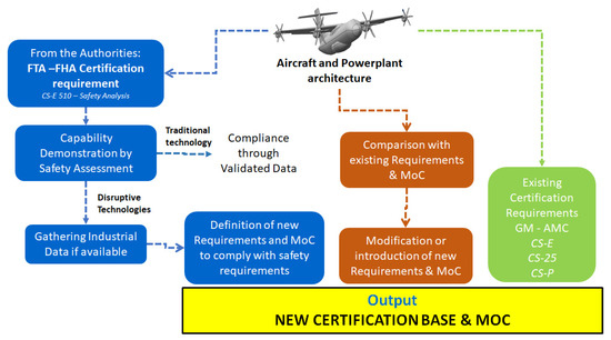
Figure 1.
Certification of disruptive technologies—schematic.
- Identification of the architecture under evaluation;
- Safety assessment for the architecture under evaluation;
- Identification of gaps and relevant means of compliance derived from the safety assessment;
- Identification of gaps and relevant means of compliance derived from comparison assessment with existing certification requirements (this step can be performed independently from the safety assessment);
- Collection of gaps identified from safety and comparison assessment and gap classification
- Gap closure:
- ○
- Collection of available standards (requirements and means of compliance);
- ○
- Correlation between gaps, available standards, and relevant system/component;
- ○
- Certification proposal.
This approach is fully integrated into the new product introduction (NPI) process, thereby minimizing future rework due to the early identification of certification issues.
2. Proposed Approach
It is necessary to further detail some of the main streams to better focus the proposed process.
2.1. Identification of the Architecture under Evaluation
The first step of the process consists of identifying the architecture under evaluation.
The architecture under test is referred to as a Regional Hybrid Platform related to an aircraft with a propulsive system with two main propellers and wing-tip propellers based on a Series–Parallel Partial Hybrid architecture (SPPH). In this configuration, a gas turbine provides thermal power to the combining gearbox, which can either combine power coming from the e-motor/e-generator (acting as a motor) to move the inboard propeller or split power between the inboard propeller and the e-generator/e-motor (acting as a generator). A Power Management and Distributor Unit (PMAD) provides the requested power to the electric motor that drives the wing-tip propeller. In addition to the thermal power provided by the gas turbine, electrical energy is provided by a battery pack (E-storage in Figure 2) and managed by the PMAD.
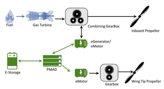
Figure 2.
General powertrain architecture for one wing.
The whole aircraft propulsive system is composed of two SPPH systems applied to both wings in combination with a unique PMAD shared by both sides linked to the four electrical motors (two for each wing) and associated with a common battery pack [6].
2.2. Safety Assessment for the Architecture under Evaluation
The safety assessment process includes requirement generation and verification, which supports aircraft development activities [7]. This process provides a methodology to evaluate aircraft functions and the design of systems performing these functions to determine if the associated hazards have been properly addressed. The system development process is iterative in nature. The safety assessment is an inherent part of this process; it begins with the concept design and derives its safety requirements. As the design evolves, changes are made, and the modified design must be reassessed. This reassessment may create new design requirements. These new requirements may necessitate further design changes. Finally, the safety assessment process ends with verifying that the design meets the level of safety required by the certification.
Based on the system architecture shown in Figure 3, a preliminary safety assessment of the aircraft under test has been evaluated, taking the standard SAE ARP 4761 as a reference [7]. The figure below reports the flow chart of the proposed approach.
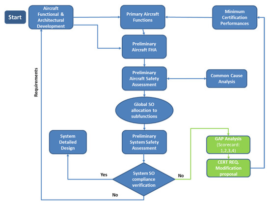
Figure 3.
Safety assessment approach proposed.
2.2.1. Functional Analysis
A primary functional analysis has been carried out starting from the aircraft design and general system architecture, in which the primary functions at the aircraft level have been identified. The following Table 1 reports an extract of the functional analysis performed, in which the traditional function of interest, “To Guarantee Thrust,”. Its safety evaluation is described in the following:

Table 1.
Preliminary aircraft functional analysis.
2.2.2. Functional Hazard Assessment of Identified Function of Interest
After identifying the traditional main functions, a Preliminary Aircraft Functional Hazard Assessment is completed. It allows for identifying and classifying the failure condition(s) associated with the aircraft functions and combinations of aircraft functions. These failure condition classifications establish the safety objectives. For the purpose of validating the certification process, it was deemed appropriate to report the same failure effects for the three main phases. The detailed evaluation of the failure effects on each individual flight phase is beyond the scope of this work.
The Table 2 reports the Functional Hazard Assessment (FHA) for the sub-function (Level 2) 2.1 “To guarantee forward thrust”.
Table 2.
Aircraft Functional Hazard Assessment.
The output of the aircraft FHA is used as the starting point for conducting the Preliminary Aircraft Safety Assessment (PASA), which consists of a systematic examination of the proposed system architecture(s) to determine how failures can cause the functional hazards identified by the FHA. The objective of the PASA is to establish the safety requirements of the system and to determine that the proposed architecture can reasonably be expected to meet the safety objectives identified by the FHA.
2.2.3. Fault Tree Analysis of Functions of Interest
Several techniques can be applied as part of the PASA to determine what single failures or combinations of failures can occur (if any) at the lower levels that might cause each failure condition, such as Fault Tree Analysis, Dependence Diagram, or Markov Analysis.
In this work, the PASA has been performed by means of Fault Tree Analysis (FTA), in which the failure conditions identified in the FHA correspond to the top events in the Fault Tree Analysis.
The analysis begins with an undesirable top-level hazard event. It systematically determines all credible single faults and failure combinations of the system functional blocks at the next lower level that could cause this event.
The Figure 4 reports the Fault Tree developed for the top event: “Total loss of thrust on both sides”, as identified in the Aircraft Functional Hazard Assessment (Table 2).
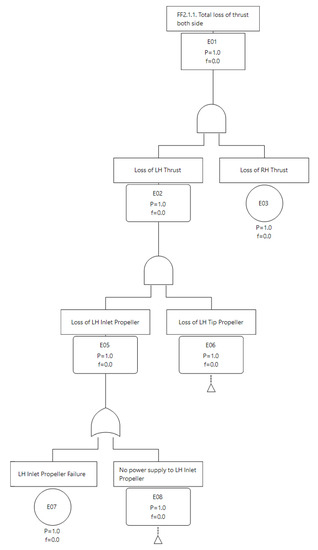
Figure 4.
Fault Tree related to the failure condition “Total Loss of thrust—both sides.”
2.2.4. FHA and FTA at System Level
After performing the FHA and PASA at the aircraft level, the safety requirements/objectives are allocated to all functions of interest. Subsequently, based on the evaluation of the critical systems, the next step consists of performing the functional analysis first. The FHA and PASA use the same techniques described above but are applied at the system level [7]. Based on the hybrid propulsion system architecture under test in Figure 1, the functional analysis at the system level is reported in Table 3. Considering that the configuration proposed in Figure 1 is the same for both left- and right-side wings, the analysis has been implemented only on the left side.
Table 3.
Preliminary System Functional Analysis.
Based on the identified functions, the Preliminary System Functional Hazard Assessment of the main functions of the hybrid propulsion system has been implemented and reported in the Table 4.
Table 4.
Preliminary System Functional Hazard Assessment.
The Figure 5 reports the Fault Tree related to the System Failure Condition: “No power was supplied to the LH INLET” propeller as identified in the System Functional Hazard Assessment.
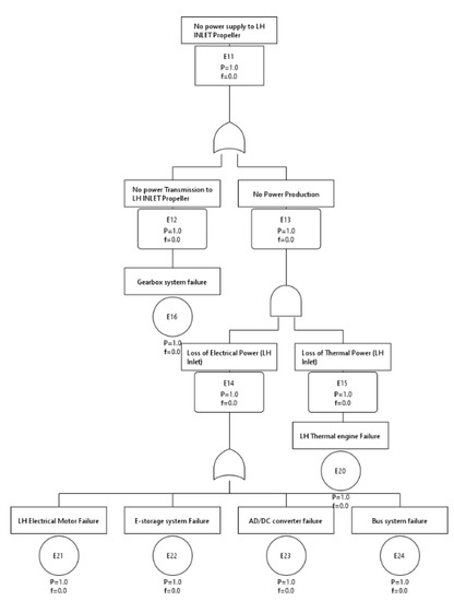
Figure 5.
Fault Tree related to the System Failure Condition “No power was supplied to the LH INLET propeller”.
After completion of the System FHA and SSA processes, the following checks can be conducted:
- Verify that the propulsive system is able to guarantee compliance with respect to the levels of severity identified in the System Hazard Analysis (Section 2.3.1);
- Preliminary verification that the propulsive system is able to guarantee compliance with respect to the levels of severity identified in the Aircraft Hazard Analysis:
If yes—the system design can move on to the next detailed design phase;
If not—at first, a new refinement of the system requirements, also verifying modifications to the architecture, is needed to try to accomplish the safety objective; subsequently, a comparison between existing requirements and MoC, based on current regulations, and the new ones identified for the system under evaluation can be made to identify gaps in requirements and means of compliance.
2.2.5. Preliminary Safety Assessment Results
In this section, a preliminary quantitative safety analysis is reported for the powertrain architecture shown in Figure 1. The analysis evaluated both sides of the aircraft, considering the failure rates of the components. However, it should be noted that the failure rates are not always provided by the suppliers or are not available at all. Thus, research on applicable standards NPRD 2016 [8] has been conducted. For each component, the failure rate of the most similar equipment has been chosen as a reference, except for the battery pack, for which the failure rate has been derived based on engineering judgment. The tool Ansys Medini has been adopted to quantitatively evaluate the FTA. A decreasing exponential reliability with a constant failure rate λ has been assumed for all components. This typical rule of reliability is reported in Equation (1):
where
λi is the failure rate of the ith component, and Ri(t) is its correspondent reliability.
Based on this assumption, a first evaluation of the probability of occurrence of the most critical failure condition at the aircraft level, characterized by the catastrophic top event “Total loss of thrust on both sides” has been executed using the Fault Tree Analysis, considering an average mission time T = 2 h.
The following figure reports an extract of the fault tree developed for the above-mentioned top event, in which two figures have been indicated:
- Top Event Probability: This option computes a point estimate of the probability at mission time T. This means that all basic events are evaluated at T, and top and intermediate events are computed for the same. The probability label shows up as P.
- Unreliability: Probability of the top event occurring in the interval [0…T]. The probability label thus shows up as f.
The figures of unreliability and probability of occurrence for the catastrophic top event analyzed are shown in Figure 6. These figures were determined using reliability data obtained from the database [8]. In cases where reliability databases are unavailable, the figures were estimated based on engineering judgment. The assessment results do not allow full compliance with the Catastrophic Safety Objective required in the System Hazard Analysis (10−9). Consequently, the analyses will be reviewed in future developments of the project in order to ensure compliance with the safety requirements. A further assessment result pointed out that the target value of the failure rate identified for the battery pack is some orders of magnitude greater than the failure rate of the other components. For this reason, the battery pack can be considered the priority equipment of the architecture under evaluation according to the certification requirements. Therefore, it will be used as an example of the new certification approach proposed.
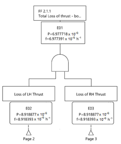
Figure 6.
Fault Tress of the top event total loss of thrust on both sides.
2.3. Identification of Gaps and Relevant Means of Compliance Derived from the Safety Assessment
The input obtained from previous steps is the severity level related to each sub-system identified through the FHA and FTA at the system level. The severity level can be classified as minor, major, hazardous, or catastrophic, depending on the effect that the failure could cause. A logical inverse relationship must exist between the severity of the failure and the average probability per flight hour to ensure an acceptable safety level (i.e., Risk Assessment), as shown in the following Figure 7, [5]:
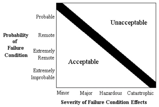
Figure 7.
Relationship between probability and severity of failure condition effects.
2.3.1. Failure Condition Requirement
This level of severity is thus associated with a minimum required criticality [9,10,11,12] (ref. CS-E 510 for engines; CS-25 for airplanes; CS-29, CS-27 for rotorcrafts), and to demonstrate this capability, a detailed FMECA needs to be performed.
- Failure modes that could cause a catastrophic failure should be shown to be extremely improbable, i.e., less than 10−9 per flight hour.
- A hazardous engine effect arising from an individual failure must be predicted to be not greater than 10−7 per engine flight hour to be acceptable.
- For major engine effects, the probability must be less than 10−5 per engine flight hour.
- A minor engine effect should be reasonably probable, meaning the failure probability should be less than 10−3 per engine flight hour.
The different maximum failure rates are addressed in different specifications. The definition of catastrophic failure and the associated probability requirement can be found in [10,11,12] but not in [9]. That is because the failure of an engine is unlikely to result in a catastrophic effect. The aircraft level specifications [10,11,12] and the engine level specification [9] define a hazardous, major, and minor effect.
2.3.2. Failure Rate Assessment—Certification Evidence and GAP
For traditional technologies, compliance with the required failure rate is obtained through validated data. However, for disruptive technologies, it is primarily necessary to demonstrate data validation [13]. This can be obtained following three steps, graphically shown in Figure 8:
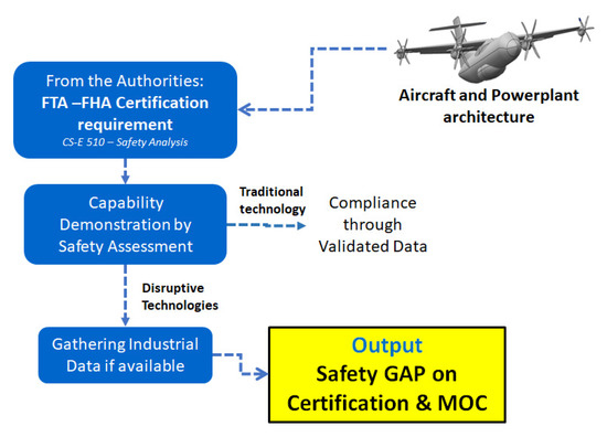
Figure 8.
Safety gap identification logical map.
- Gathering industrial data on similar applications if available;
- Definition of suitable requirements and means of compliance for the specific application;
- Comparison of these requirements and means of compliance with those that already exist.
Thus, if there is no matching between steps 2 and 3, safety gaps in requirements and means of compliance are identified.
An example of gap identification is reported in Table 5.
Table 5.
Example of the gap identified.
2.4. Identification of Gaps and Relevant Means of Compliance Derived from Comparison Assessment with Existing Certification Requirements
It is to be noted that this certification comparison will be provided considering that the current certification process divides the requirements into dedicated sections for engines, propellers, aircraft, and helicopters. This division hardly matches the evaluation of an innovative architecture, where, for example, the evaluation of a propulsion system needs to include the analysis of requirements from different sections. It is important to carefully evaluate the complete panorama of the certification requirements; the logical map of what has just been described is shown in Figure 9. Further details can be found in [14].
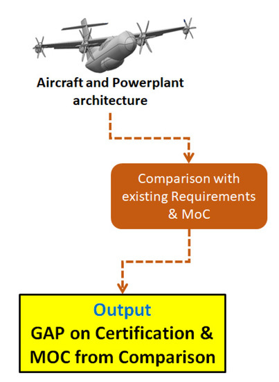
Figure 9.
Comparison gap identification logical map.
An example of the different requirements provided by the authority: EASA CS-E for engine, CS-P for propeller, and CS-23 for normal, utility, aerobatic, and commuter aeroplanes [9,15,16], can be summarized in the following Table 6 for hybrid-electric propulsion systems—HEPS gap analysis.
Table 6.
Gap analysis on current certification requirements.
2.5. Collection of Gaps Identified from Safety and Comparison Assessment and Gap Classification
The classification of the analyzed requirements is necessary to clearly picture their status as requirements and means of compliance.
The classification, reported in Table 7, is based on the evaluation of gap extension.
Table 7.
GAP classification matrix.
- Level 1: No change is required. Regulation and relevant means of compliance are already in line with the new technology;
- Level 2: The requirement is suitable for the new technology. The means of compliance need to be updated to address the new technology;
- Level 3: The requirement and relevant means of compliance need to be modified to include the new technology;
- Level 4: Both requirements and means of compliance do not exist. New ones need to be introduced.
This classification allows us to properly address the activities dedicated to filling up these gaps, providing a clear understanding of the effort needed to close them.
The higher classification rating means a gap where new regulations and means of compliance are needed. In such cases, the certification demonstration is expected to be very complex and require integrated system testing. Additionally, the technical risk associated with certification may impact the general feasibility of the system.
The collection of the identified gaps and relevant means of compliance derived from the safety and comparison assessment is consequently classified according to the above-mentioned criteria.
2.6. Gap Closure-Menù
A potential gap closure approach is represented by the concept of ‘certification à la carte’ [17]. This is based on the assumption that the new disruptive technologies differ considerably. Therefore, the certification process should not be universally standardized but tailored to the specific project.
To apply this approach, we first need to create the ‘Menù,’ namely, the collection of available standards (requirements and means of compliance) to comply with functionality and safety requirements. To accomplish that, we shall gather the currently available certification requirements (already assessed special conditions, industrial standards, and experimental data) and identify the main areas where such certification is lacking.
Once we have a complete selection, we can build a tailored specification and relevant means of compliance for our project, selecting the relevant specifications from the list of standards we created previously.
Organizing the requirement and means of compliance collection is useful for adopting the already available taxonomy and system architecture defined in the GAP process identification.
We can analyze this concept more thoroughly by organizing it in the following steps:
- Collection of available requirements—Search for the available standards and their records according to the taxonomy correlation;
- Collection of available means of compliance—Search for the available means of compliance and their records according to the taxonomy correlation.
To simplify the collection, it is also desirable to identify the certification requirements and MOC pool by type of technology (hybrid-electric, fuel cells, H2 direct burn, etc.).
3. Case Study
An Example of collection for available requirements is provided in the Figure 10 (pool requirements—system matrix):
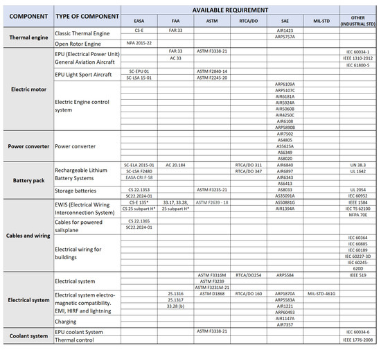
Figure 10.
Example of collection of available requirements for the propulsion system.
Pool—electric/hybrid electric propulsion
System—propulsion system.
3.1. Correlation between Gaps and Relevant System/Components
Based on the architecture under evaluation, a multilevel matrix is arranged.
- Divide the specification requirements at the system and sub-system level (lubrication, cooling, propulsion system, etc.);
- Divide the specification requirements by component type (electric motor, cables, batteries, etc.). It should be noted that the same component can be found in several systems.
The Figure 11 shows a schematic organization of the multilevel matrix.
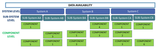
Figure 11.
Correlation between gaps and relevant system/components.
This multilevel matrix comes out particularly handy, considering that it is based on the initial taxonomy used in all steps of this process. This underlines the organic nature of the process.
Furthermore, the level of detail (i.e., the number of considered systems and sub-systems) adopted for the matrix organization is aligned with the whole process phase.
An example can make things clearer. Let us suppose that we have already created and properly organized the requirements pool. We are designing a generic aircraft with a hybrid-electric propulsion system, and we are interested in the certification of the battery pack, which is composed of lithium batteries.
The multilevel matrix can be summarized as reported in the following Figure 12:
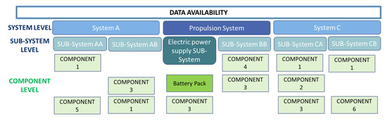
Figure 12.
Multilevel matrix for propulsion system battery pack.
To properly identify the available requirements and means of compliance, we consequently choose on the matrix pool the area relevant to the hybrid propulsion, the system as propulsion, the sub-system as electric power supply, and the component as a lithium battery pack. The Table 8 reports the available requirement for battery pack.
Table 8.
Available requirements for a battery pack.
Pool—electric/hybrid electric propulsion
System—propulsion system.
Sub-system—electric power supply
3.2. Gap Closure—Certification Proposal
The identification of applicable requirements and relevant means of compliance for the architecture under evaluation is summarized in the proposal for the certification plan.
A similar approach can also be followed to demonstrate the flight clearance of a prototype that usually represents the first step to demonstrate the airworthiness of the architecture under evaluation.
It is important to provide the initial gap classification in the proposal of the certification plan to better address the discussion with authority, prioritizing the gaps with higher scores.
The following drivers can address the assessment with the authority:
Identification of one or more specification requirements that potentially cover, even if with some modification, the certification process for the component (gap classification = 1, 2, or 3). Consequently, with the agreement of the authority, we will proceed to perform the certification process described in the specification(s) to validate the component.
Suppose a suitable specification requirement is not identified (gap classification = 4). In that case, it is necessary to proceed with a deeper investigation by involving the authority to identify and agree on a specific validation process for the component. The pool matrix should be the starting point for this investigation.
An example of the proposed certification requirements applied to a HEPS is summarized in the Table 9.
Table 9.
Most relevant certification gaps.
A detailed example of innovative means of compliance for a HEPS (ground test) is provided in [18].
4. Discussion
The proposed methodology aims to handle two different methods in parallel, reversing and mixing the usual certification approach. At first, the system safety assessment is adopted to identify the “criticality” of the system components relative to the available requirements. Subsequently, a comparison is made between the identified criticality and the existing certification requirements. The results of these two flows are merged into a single list of gaps and classified. When this step is completed, a detailed list of requirements—new, to be modified, or existing—available to start the certification activity can be identified.
This approach for the certification of disruptive technologies would provide a structured process to better assess the incoming needs to support the industries proposing innovative solutions for air mobility.
The proposal originated from the concept of “certification a la Carte” provided by EASA [8] and developed this approach into a structured process available for applications.
Nevertheless, this process needs to be verified in a real application, and feedback to tune it should be collected.
In the future, this approach will be further refined to make it applicable to new configurations and disruptive technologies. These developments may arise in the framework of new research programs funded by the European Community. Moreover, the proposed methodology aims to support the competent authorities in defining new requirements and means of compliance for innovative/disruptive technologies that complement current regulations.
Author Contributions
Conceptualization, G.B., L.T., A.V., M.B., V.M., E.Q. and M.G.; methodology, G.B., L.T., A.V., M.B., E.Q., C.C., V.M. and M.G.; software, G.B. and L.T.; validation, G.B., L.T., M.B., E.Q., V.M. and M.G.; formal analysis, M.B., V.M. and E.Q.; investigation, M.B., E.Q., C.C., V.M. and M.G.; resources, L.T., M.B. and A.V.; data curation, G.B., V.M. and E.Q.; writing—original draft preparation, G.B., L.T., M.B., E.Q., V.M. and M.G.; writing—review and editing, G.B., L.T., A.V., M.B., E.Q., V.M., C.C. and M.G.; visualization, G.B., L.T. and M.B.; supervision, L.T., M.B., C.C. and A.V.; project administration, A.V. and M.B.; funding acquisition, A.V. and M.B. All authors have read and agreed to the published version of the manuscript.
Funding
This research was funded by the Clean Sky 2 Joint Undertaking, grant agreement No. 699715, the Regional Innovative Aircraft Demonstration Platform (REG IADP) project.
Data Availability Statement
The safety assessment was performed through input data partly derived from standards that are not sharable due to legal issues and partly from intellectual property rights issues. However, the databases used for gap analysis have been referenced within the paper.
Acknowledgments
Dedicated acknowledgment is provided to the GE Aerospace NTI team that provided inspiration and revised some of the contributions included in this paper.
Conflicts of Interest
The authors declare no conflict of interest. The funders had no role in the design of the study; in the collection, analyses, or interpretation of data; in the writing of the manuscript, or in the decision to publish the results.
References
- Diekmann, F.; Kortemeier, E. Certification Process for a Hybrid Electric Aircraft. February 2022. Available online: https://www.speedgoat.com/Portals/0/adam/Blog4/VrwADNqCvEKszSgbxBHyCw/Link/Whitepaper_Certification.pdf (accessed on 14 July 2023).
- Diaz-Guardamino, I.E.; Salas, M.S.; Nüsseler, M. Challenges Associated to High Power Hybrid Electric Propulsion in Aerospace; NATO: Brussels, Belgium, 2019. [Google Scholar]
- Bowman, C. Visions of the Future: Hybrid Electric Aircraft Propulsion. In Proceedings of the AIAA Aircraft Elec-tric/Hybrid-Electric Power & Propulsion Workshop, Salt Lake City, UT, USA, 28 July 2016. [Google Scholar]
- Denham, C.L.; Jansen, R. Initial Regulatory and Certification Approach for the SUSAN Electrofan Concept. In Proceedings of the AIAA SciTech Forum Conference, San Diego, CA, USA, 22 November 2021. [Google Scholar]
- FAA AC 25.1309-1A—System Design and Analysis. Available online: https://www.faa.gov/documentLibrary/media/Advisory_Circular/AC_25_1309-1A.pdf (accessed on 9 June 2023).
- Lents, C.E.; Hardin, L.W.; Rheaume, J.; Kohlman, L. Parallel Hybrid Gas-Electric Geared Turbofan Engine Conceptual Design and Benefits Analysis. In Proceedings of the AIAA/SAE/ASEE Joint Propulsion Conference, Salt Lake City, UT, USA, 25 July 2016. [Google Scholar]
- SAE International. Available online: https://www.sae.org/standards/content/arp4761/ (accessed on 7 March 2023).
- Nonelectronic Parts Reliability Data Publication (NPRD-2016). Available online: https://www.quanterion.com/product/publications/nonelectronic-parts-reliability-data-publication-nprd-2016/ (accessed on 14 July 2023).
- EASA CS-E Engines. Available online: https://www.easa.europa.eu/en/downloads/116287/en (accessed on 8 March 2023).
- EASA CS-25 Large Aeroplanes. Available online: https://www.easa.europa.eu/en/downloads/136622/en (accessed on 8 March 2023).
- EASA CS-27 Small Rotorcraft. Available online: https://www.easa.europa.eu/en/downloads/137584/en (accessed on 8 March 2023).
- EASA CS-29 Large Rotorcraft. Available online: https://www.easa.europa.eu/en/downloads/137588/en (accessed on 8 March 2023).
- NTRS—NASA Certification Rules and Standards Review. Available online: https://ntrs.nasa.gov/api/citations/20190033235/downloads/20190033235.pdf (accessed on 10 March 2023).
- Schlickenmaier, H.; Voss, M.G.; Wilkinson, R.E. Certification Gap Analysis; Nasa Technical Report Server—NTRS: Washington, DC, USA, 2019.
- EASA CS-P Propellers. Available online: https://www.easa.europa.eu/en/downloads/116291/en (accessed on 8 March 2023).
- EASA CS-23 Normal, Utility, Aerobatic and Commuter Aeroplanes. Available online: https://www.easa.europa.eu/en/downloads/116297/en (accessed on 8 March 2023).
- EASA Webinar. Available online: https://www.easa.europa.eu/en/downloads/128936/en (accessed on 9 March 2023).
- Dyson, R. Chapter 6 Hybrid Electric MC-12 Ground Testing Plan Chapter. In NATO Hybrid Electric MC-12 Development Plan; NASA: Washington, DC, USA, 2020. [Google Scholar]
Disclaimer/Publisher’s Note: The statements, opinions and data contained in all publications are solely those of the individual author(s) and contributor(s) and not of MDPI and/or the editor(s). MDPI and/or the editor(s) disclaim responsibility for any injury to people or property resulting from any ideas, methods, instructions or products referred to in the content. |
© 2023 by the authors. Licensee MDPI, Basel, Switzerland. This article is an open access article distributed under the terms and conditions of the Creative Commons Attribution (CC BY) license (https://creativecommons.org/licenses/by/4.0/).