Article

Improving the Aerodynamic Performance of WIG Aircraft with a Micro-Vortex Generator (MVG) in Low-Speed Condition

by
Zinnyrah Methal
1,
Ahmad Syahin Abu Talib
1,
Mohd Supian Abu Bakar
2,*,
Mohd Rosdzimin Abdul Rahman
1,2,
Mohamad Syafiq Sulaiman
1 and
Mohd Rashdan Saad
1,2,*
1
Department of Aeronautic Engineering and Aviation, Faculty of Engineering, National Defence University of Malaysia, Kem Perdana Sungai Besi, Kuala Lumpur 57000, Malaysia
2
Centre for Defence Research and Technology, CODRAT, National Defence University of Malaysia, Kem Perdana Sungai Besi, Kuala Lumpur 57000, Malaysia
*
Authors to whom correspondence should be addressed.
Aerospace 2023, 10(7), 617; https://doi.org/10.3390/aerospace10070617
Submission received: 10 March 2023 / Revised: 17 June 2023 / Accepted: 26 June 2023 / Published: 5 July 2023
(This article belongs to the Special Issue Flow Control and Drag Reduction)

Abstract

:
This present study investigated the potential of passive flow control to reduce induced drag by using a micro-vortex generator (MVG) at a backward-facing step (BFS) location. A wing-in-ground (WIG) craft is a fast watercraft that resembles a dynamically stabilised ship that can move or glide across the surface of water or land. Therefore, the wing of the WIG is designed to glide when in contact with water, which helps to decrease drag and enhance the lift of the overall vehicle. However, the existing design of the hull-fuselage of WIG tends to induce more drag during the flight, especially at a flow downstream of a BFS, which will cause inefficient fuel consumption over the distance travelled. MVG with the ramp type was chosen and tested at various angles (°) and heights (h). The angles (°) tested were 12°, 16°, and 24°, while the heights (h) tested were 0.4 δ, 0.6 δ, and 0.8 δ, where δ refers to the boundary layer height. The model was designed and fabricated using a 3D printer. The 3D model was tested in a subsonic wind tunnel at Re = 6.1 × 10 4 m−1 to 6.1 × 10 5 m−1 between 1 and 10 m/s. This study demonstrated that the most effective angle and height of MVG for reducing the drag coefficient were 16° and 0.6 δ, respectively. In comparison to an uncontrolled case, the drag coefficient decreased significantly by 38% compared to the baseline.

1. Introduction

A wing-in-ground (WIG) craft is one of the emerging aviation technologies that offers low fuel consumption, high cruising speeds, and safer flight operations [1,2,3]. It has been widely used in many application forms, such as military [4], cargo transportation [5], rescue operations, and tourism [6]. Unlike commercial aircrafts, WIG is uniquely designed to take advantage of the ground effect to fly. The key benefit of ground effect vehicles is that the wing experiences a reduction in induced drag and the presence of an effective air cushion, which leads to an increased lift-to-drag ratio when in close proximity to the ground.
Allegedly, WIG has a minimum amount of drag, as it flies close to the ground. However, the existing fuselage design has an element of discontinuity known as the stepped hull. The idea of WIG design originally came from the design of flying boats, which supposedly contributes to higher levels of lift. Nevertheless, due to the existence of stepped hulls, the flow experiences discontinuity and causes significant viscous drag because of the presence of flow separation. This condition, which is known as backward-facing step (BFS), affects the lifting condition of the craft separately to the wing itself. Many studies have been conducted to study the effects of the wing characteristics of WIG; however, very few studies have focused on the fuselage, which significantly contributes to an increase in aerodynamic drag during airborne operations due to the effect of a stepped hull.
Backward-facing steps, also known as “sudden expansion flows” or “backward flows”, have been continuously investigated for more than five decades [7]. BFS involves several fundamental aspects of general separated flow, such as free shear flow separation, vortex formation, the recirculation region, and reattachment. Such a flow may yield a dramatic loss in heat transfer, an increase in drag penalty, and a decrease in pressure growth [8].
Meanwhile, Chen et al. [7] reviewed details on the geometrics and flow physics of the backward-facing step. From the perspective of flow dynamics, BFS typically occurs when there is a sudden change in geometry that causes the flow to change direction, and, hence, separates the boundary layer at the step of the edge. Thus, a large separation vortex is formed, followed by a tiny vortex in the corner further downstream. In addition, complex vortex series can occur under various Reynolds numbers and geometric circumstances [9]. After the separation, the flow basically behaves as a free shear layer, with a high-speed fluid on one side and low-speed fluid on the other. The shear layer affects the surface for some distance downstream and creates a closed recirculation area with a turbulent, upstream-moving fluid. There may also be a minor “corner eddy” in this area, which rotates in the opposite direction from the main recirculating flow. Reattachment occurs at some point in the step region, and the flow is found to be unstable. As the flow moves downstream of the reattachment point, the boundary layer starts to redevelop. Figure 1 shows a typical visualization concept for the separation and reattachment processes in the flow field region of BFS.
The simplicity of the BFS shape makes it an excellent tool for studying the complexity of the flow phenomenon via experimental and numerical analyses. Pouryoussefi, Mirzaei, and Hajipour [11], and Huang and Yan [12] investigated the effects of pressure changes on the size of separation bubbles in low-speed and high-speed flows. In different studies, Grandemange et al. [13] and Li et al. [14] studied the effect of geometry, such as sideslip yaw angle, length, and height, on the pressure and drag force at the BFS location. Collectively, these studies contributed to understanding the flow around BFS, which can potentially harm a wide range of engineering applications, including thermal systems, chambers, etc. However, there is very limited study focusing on the effect of the lifting part of a WIG that has a stepped hull, which can cause a discontinuity in the flow. This discontinuity can increase the viscous drag because of the presence of flow separation. Eventually, the separated flow can affect the stability of the craft and cause a catastrophic accident if not properly controlled.
Moreover, the application of a flow control device at the BFS location can reduce the drag formation over the fuselage. There are two basic flow control devices: active flow control and passive flow control. Active flow control requires external devices to operate, whereas passive flow control acts independently throughout the whole system. Examples of active flow control are plasma actuators [15], suction and blowing [16,17], and synthetic jets [18,19]. According to Ruisi et al. [20], the plasma actuator is capable of reducing the separation length at the flow field with an accurate modulation frequency. In contrast, the study by Xu et al. [21] found that the structure of the shear layer is greatly affected by the jet slot angle and frequency. The best configuration is found to be 127.5° and with a vortex frequency of 35 Hz. The micro-vortex generator (MVG) (vane-type and ramp-type) [22], bump [23,24], slot [25], and oscillating cylinder [26] are common approaches that are introduced in the case of passive flow control. Meanwhile, Syahin et al. [5] investigated the communication of MVG, using a micro-ramp, with the drag coefficient on WIG. The result indicates a decrease in the drag coefficient of 21% compared to the baseline case. A similar study by Said et al. [6] demonstrated the effect of employing micro-vane as a flow control device on BFS over the hull fuselage of the WIG at various device heights (h = 0.4 δ, 0.6 δ, and 0.8 δ), angles (α = 10°, 16°, and 23°), and spacing (δ = 3.1 δ, 3.6 δ, and 4.1 δ). They found that the drag coefficient can be reduced by up to 25% with the installation of the micro-vane. Although the ground effect over the fuselage has already been covered, there has only been one study covering the effect of the micro-ramp towards the BFS location, which only involved a single configuration [5]. There is still an unclear explanation regarding how the micro-ramp affects the BFS location, and no detailed explanation of the effect of the micro-ramp towards the aerodynamic drag over the stepped hull has been provided yet.
More research on the aerodynamic properties of the fuselage is required to improve the efficiency of WIG operation. Therefore, this study aims to investigate the effect of a passive flow control device on the drag coefficient, specifically at the BFS location. The type of MVG studied is a micro-ramp at various angles (θ) and heights (h). The MVG will be tested at different velocities ranging from 1 to 10 m/s. The flow characteristics over the passive flow control device will be examined in this investigation, and the device is expected to reduce drag formation while also improving the aerodynamic performance of the WIG.

2. Methodology

2.1. Design and Fabrication Process of Fuselage

The model used for this investigation is the hull-fuselage part of WIG, which is tested in the presence of MVG as the flow control device, as indicated in Figure 2. The fuselage is designed using computer-aided design (CAD) software for better precision and modification. The fuselage model has dimensions of 0.33 m length, 0.07 m width, and 0.09 m height, which are similar to those used in a work by Said et al. [6]. Figure 3 shows the geometry of the step underneath the fuselage.
For the fabrication process, 3D printing was used to create three-dimensional (3D) objects through a layering technique. In this experimental work, the 3D printer models used were CR10-4S and CR10-5S. The glass bed top’s measurements for CR10-4S and CR10-5S were 400 mm (X, Y, Z) and 500 mm (X, Y, Z), respectively. The glass bed top has a removable glass sheet that can easily detach the printed model from the bed. The nozzle diameter is 0.4 mm, with a tolerance printing in between 0.3 mm and 0.4 mm. For better results, the printing speed was set to 50 mm/s to reduce the momentum effect that might disturb the printing process. The infill density was set to 30% for stiffer and sturdier models. The material used for printing was polylactic acid (PLA) with a diameter of 1.75 mm. PLA is practical for this research due to its low melting point, low energy requirements, non-toxic nature, and inexpensiveness compared to other materials.
During the printing process, support was included to ensure that the complex parts were not crooked or separated. When the printing is over, sanding is highly recommended to remove the layer lines, rafts, or support materials on the model surface. These defects can result in higher skin friction drag in addition to poor aerodynamic performance [27]. The proper way of sanding is to start with medium-grit sandpaper and slowly increase the grit until very fine to obtain a smooth surface. For a smoother surface, coating is suggested when the sanding process is over. The coating suggested is the putty primer. Figure 4 shows the fuselage model after conducting the post-processing steps.

2.2. Micro-Vortex Generator (MVG) Device

Micro-ramp is a subgroup of micro-vortex generators, with a wedge-shaped blade that can produce a counter-rotating vortex pair downstream of the MVG. A study proved that ramp-type MVG can reduce the flow separation induced by boundary layer interaction for both low-and high-speed flows by enhancing the vortex intensity in the flow field [28]. Due its effectiveness, the simple shape of the ramp-type device and its ease of installation make it the best option for a flow control device (see Figure 5). The ramp-type configuration consists of ramp width (d), ramp length (ℓ), ramp height (h), ramp angle (α), and apex angle (β), as shown in Figure 5.
MVG features commonly have a height smaller than the boundary layer thickness. Previous studies [5,6,29,30] have used a similar height as Ford and Babinsky [31] to test the configuration under subsonic flow. Therefore, due to similar intentions, this study used the same configuration as Ford and Babinsky [31] to observe the effect on flow separation via the aerodynamic drag reaction under low wind speed conditions. Table 1 shows the detailed geometries of the MVG. The boundary layer height obtained is 3 mm, which is comparable to the work of Said et al. [6].
For MVG, important parameters we considered were the angle and height of the vortex generator (VG). These were consistent with the findings of previous studies [32,33]. Concerning the effect of MVG on drag coefficient and on the fuselage of WIG, the effects of the angle and height of VGs were tested for different configurations. There were three different configurations of ramp-type vortex generators studied for both angle and height (see Table 2). It has been proven that the angle and height selected can improve the lift-to-drag ratio based on the previous work of Said et al. [34]. The VG’s devices are located spanwise along the fuselage and are situated close to the step foot. This position was chosen as a result of a prior study, which found that placing the flow control close to the step edge can maximise its effectiveness in reducing the drag induced by the step [35].

2.3. Experimental Set-Up

The experimental work in the wind tunnel was performed at extremely low speeds, between 1 and 10 m/s. To simulate the identical state of aerodynamic performance of the WIG aircraft, a ground plate made of polypropylene (PP) was mounted below the fuselage and secured in the test section. In this experiment, a stationary ground plate was installed inside the test section. Previous studies conducted by van Sluis et al. [36] and He et al. [37] have confirmed that the effect of using stationary and moving ground plates is similar in providing the ground effect towards the installed model inside the wind tunnel. The distance between the fuselage and the ground plate was 5 mm with an accuracy of ±1%. Figure 6 shows the arrangement of work of the fuselage for aerodynamic drag testing.
The wind tunnel was equipped with a three-component force balance that measured the axial, normal, and moment forces of the model to represent the condition of aerodynamic loads. The accuracy of the force balance is 1% of the full-scale range, which corresponds to ±0.3 N for lift force and ±0.2 N for drag force. The error propagation of the overall drag coefficient is ±1% of the full-scale range. Therefore, the magnitude of the measured drag force was found to be within the sensitivity limit of the force balance.
To test the model, a steel-connecting rod was inserted into the side of the fuselage where the centre of gravity is located. The upper part of the fuselage was facing the wall, while the bottom part was facing the ground plate. This arrangement was made to ensure that the force balance could generate the correct data, since the axial force of the force balance was applied towards the gravity direction.

2.4. Aerodynamic Performance

In aerodynamic research, a wind tunnel is a tool of measurement used to carefully examine the effects of airflow through solid objects. It is used to replicate the actual wind conditions to test the aerodynamic behaviour of the model. The data gathered from the wind tunnel include the lift, drag, and moment forces, as mentioned in the previous subsection. Since the drag force is the major concern regarding the fuselage, the drag coefficient ( C D ) is the primary result in this study. The calculations of C D values were determined using the following equation:
C D = 2 F D ρ V 2 A
where F D is drag force (N), ρ is the air density ( k g / m 3 ), V is the wind tunnel velocity (m/s), and A is the area of the fuselage facing the freestream flow ( m 2 ).

2.5. Subsonic Wind Tunnel Facility

The experiments were conducted in a subsonic wind tunnel at Universiti Pertahanan Nasional Malaysia (UPNM). It is an open circuit wind tunnel with a speed range of 0 to 105 m/s, which is equivalent to a Mach number of 0.3. The test section has dimensions of 0.3 m × 0.3 m × 1 m and a wall thickness of 10 mm. It has multiple fans that can be controlled by varying the frequency at the control system. Figure 7 below shows the view of the wind tunnel system utilised in this study.
The primary elements of the wind tunnel are the honeycomb, settling chamber, screens, contraction, test section, diffuser, and fan. For the uniformity of the flow in the tubular passage, all components are crucial to obtain the accurate data; Figure 8 shows the details of the open-circuit wind tunnel schematic design in UPNM.
From the measurement of turbulent intensity, the average value of turbulent intensity for three different locations in the test section is 1.4% for low speed (0.5 to 10 m/s) and 0.3% for high speed (5 to 100 m/s). It can be concluded that the wind tunnel has low velocity fluctuations and variations, and the effect of turbulent intensity due to the test section boundary layer wall can be negligible. Therefore, no correction is required for any experimental study, considering the value still lies within the acceptable range, which is less than 10% [38].

3. Results and Discussion

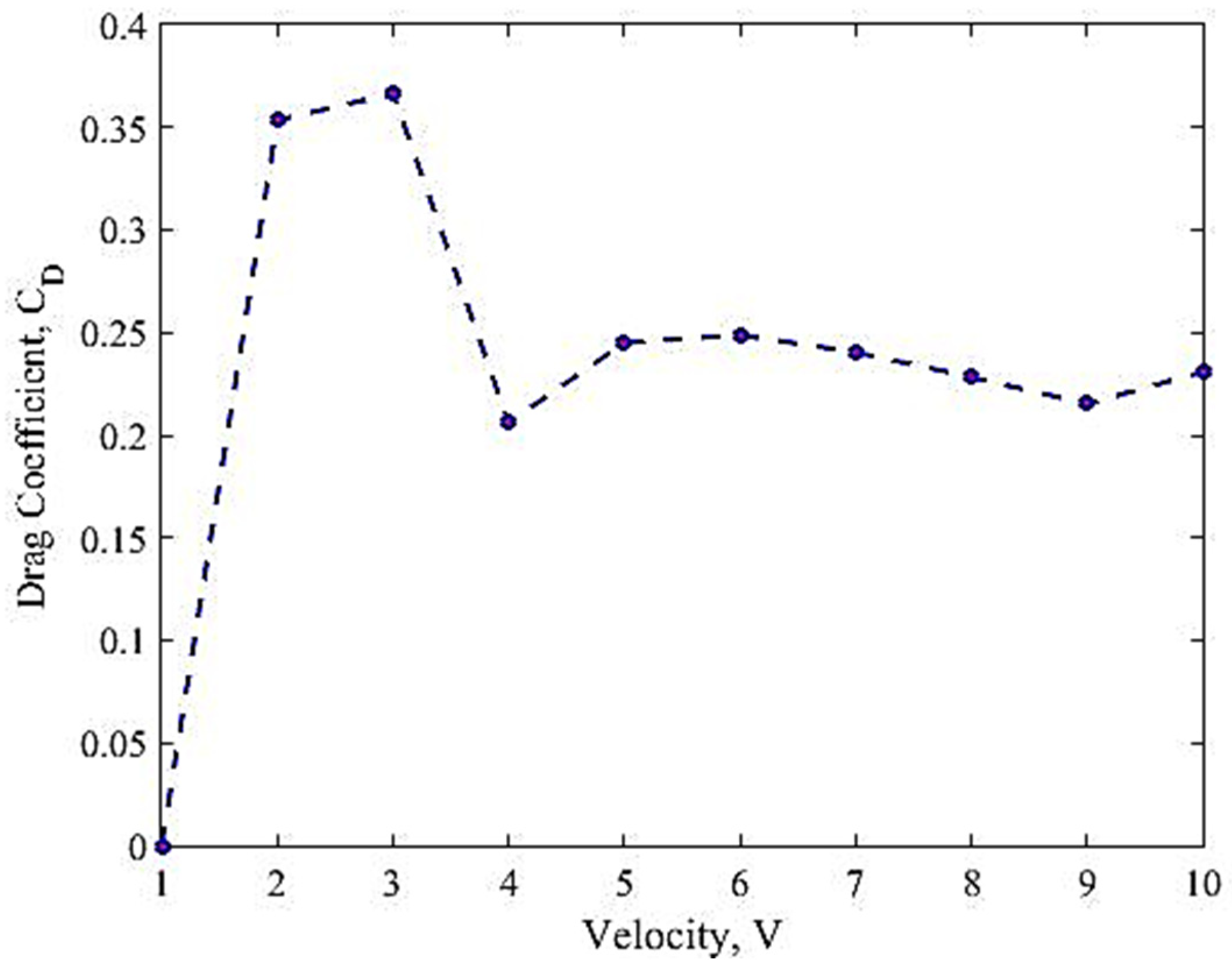
3.1. Uncontrolled Case of Aerodynamic Performance

To establish a baseline for comparison with the micro-ramp slot, the WIG fuselage was first evaluated with a baseline slot model slot, which is a slot without any flow control. Wind speeds ranging from 1 to 10 m/s were applied to the fuselage, which is between Re = 6.1 × 10 4 m−1 and 6.1 × 10 5 m−1. Figure 9 demonstrates the results of the drag coefficient ( C D ) with various velocities.
From Figure 9, it is apparent that C D is significantly higher at V = 3 m/s, where C D = 0.367. It continues to rise prior to the velocity until it reaches its maximum value. This can be explained by the effect of a large adverse gradient at a very low velocity. Based on the literature review, it can be noted that the behaviour of the laminar boundary layer at low Reynolds numbers significantly affects the aerodynamic performance of the flow field [39]. The laminar boundary layer over a BFS is more susceptible to an adverse pressure gradient, which is the primary cause of flow separation and the formation of a recirculation zone. When the momentum is insufficient, the flow downstream is unable to overcome a large adverse pressure gradient at the step due to flow separation and high turbulent movement [40]. When there is an increased shear stress between the fluid and the wall, it can result in higher drag formation. However, as the velocity increased further to above 4 m/s, the momentum transfer and the separation improved significantly. This explains the positive effect on C D as the velocity increases. Although the C D did not decrease significantly between 4 and 10 m/s, these findings demonstrated that increased velocity at the step’s edge can improve the formation of boundary layer separation.

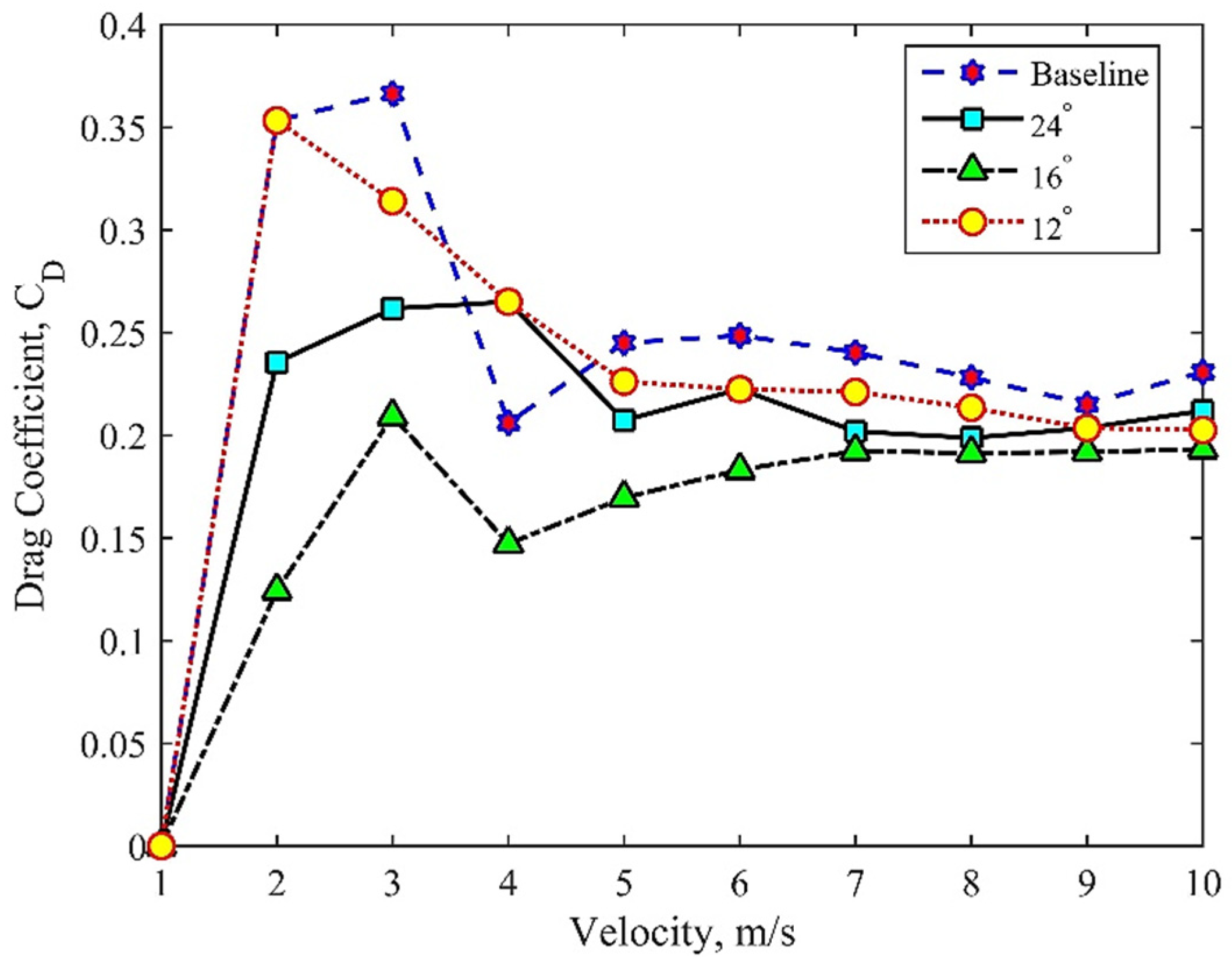
3.2. Effect of Micro-Ramp Angle towards Aerodynamic Performance

Figure 10 shows the results of the drag coefficient ( C D ) of the fuselage with a micro-ramp at different angles. The baseline case has been included to observe the change in C D , where the angles tested are 12°, 16°, and 24°. From the graph shown in Figure 10, there was a substantial difference between the baseline case and the case with MVG flow control.
For a micro-ramp with an angle of 12°, the micro-ramp has no effect on C D at V ≤ 2 m/s as it is similar to the baseline. However, as the velocity increases, a slight difference is observed for 3 ≤ V ≤ 10, where a 4.4% reduction in C D is seen compared to baseline. A significant improvement in MVG in the aerodynamic performance was observed at the angle of 16°, where it showed the lowest C D over the velocity. C D m a x and C D m i n for 16° were determined at 3 m/s and 2 m/s with values of 0.209 and 0.1245, respectively. In comparison to the baseline, the C D values were reduced up to 37% by setting up the angle to be 16°.
Interestingly, the data show that the orientation angle of 24° does not affect the drag coefficient as much as it does at 16°. The angle of 24° shows a positive decrease at the start of velocity, which is between 1 ≤ V ≤ 3. Nevertheless, C D becomes significant at 4 m/s and the behavior is nearly close to the angle of 12° at 5 m/s and beyond. In this part, it can be seen that the MVG has a little effect on C D as the angle keeps increasing. However, the percentage reduction is approximately 14%, which is greater than the orientation angle of 12° in comparison to the baseline case. This result is in agreement with Said et al.’s [6] findings, which showed that an angle of 16° was the best angle for MVG with a minimum drag coefficient. Hence, it is important to note that the MVG’s angle does indeed influence the drag coefficient around the fuselage.

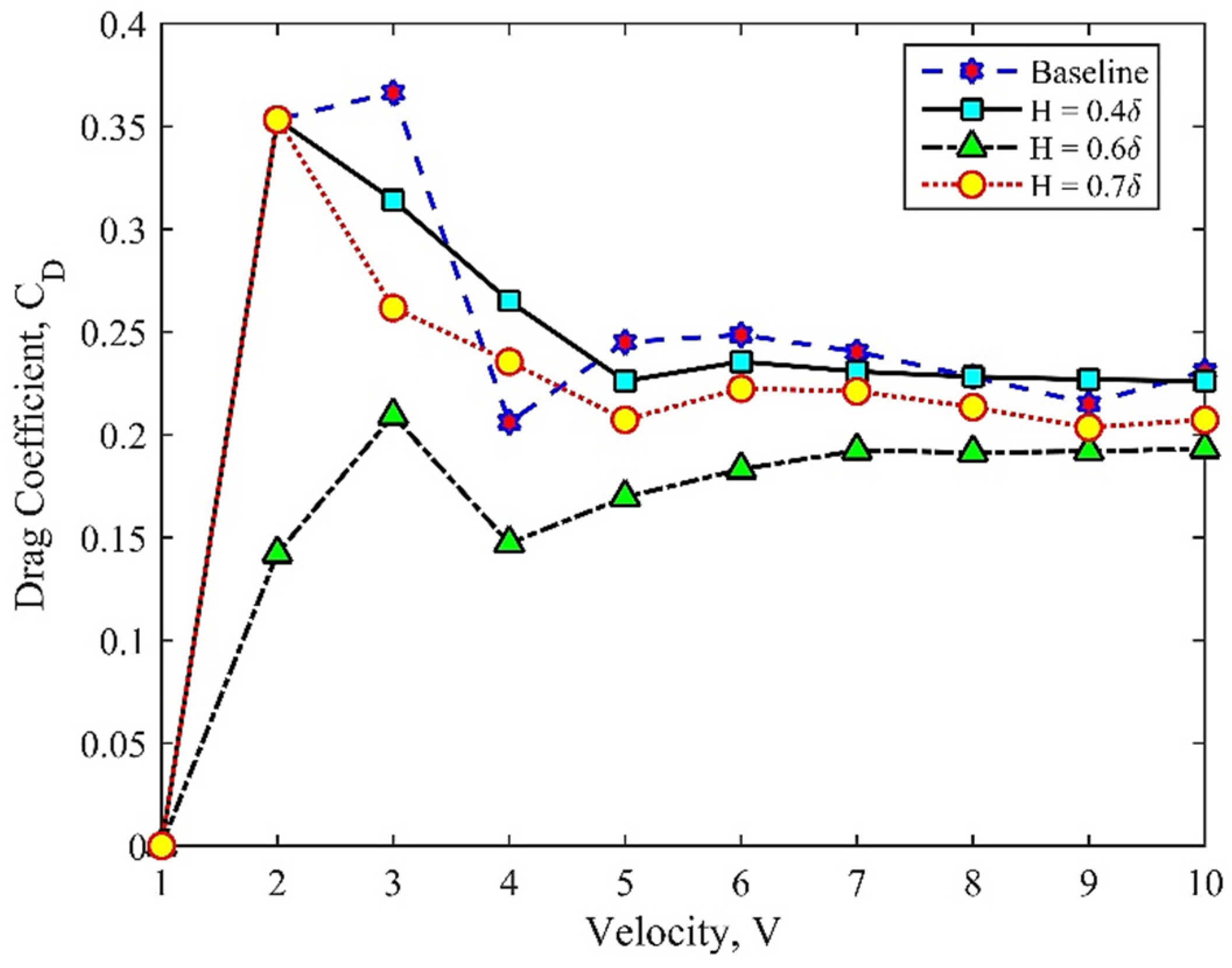
3.3. Effect of Micro-Ramp Height towards Aerodynamic Performance

In this section, the effect of MVG height on the fuselage was investigated. The 16° angle of the micro-ramp was used to determine the optimum height of the micro-ramp for reducing the drag coefficient. The heights tested were 0.4 δ, 0.6 δ, and 0.8 δ and the results are shown in Figure 11.
The graph in Figure 11 demonstrates that the height influences the drag coefficient for MVGs. Figure 11 shows that, overall, the presence of the MVG managed to reduce the drag coefficients compared to the baseline case. It was observed that a height of 0.4 δ did not reduce the drag coefficient significantly. This might be due to the small size of MVG, which is not capable of generating large vortices to assist in controlling the boundary layer. A comparable explanation is obtained in reference [33]. A similar reaction was observed for a thickness of h = 0.8 δ. In the range of 2 to 5 m/s (h = 0.4 δ), C D falls linearly below the baseline, and there is no significant decrease afterwards. The reduction recorded was about 1.2% from the baseline.
The enhancement of C D was found at an MVG thickness of h = 0.6 δ. Overall, the MVG had a significant impact on this measure. The highest C D was obtained at V = 3 m/s, where C D = 0.209, and the lowest C D = 0.1417 was at V = 2 m/s. The percentage decrease was 38% compared to the baseline. The presence of MVG creates vortices that travel downstream and enhance the mixing with the freestream flow. The vortices energise the flow and cause the freestream flow to be more robust and less susceptible to flow separation at the BFS; this finding corresponds with that of Hilo et al. [41]. The reduction in C D was observed after 3 m/s for MVG with h = 0.8 δ, but the aerodynamic performance was not significant when compared to 0.6 δ. The reduction rate was 9% from the baseline case.
In conclusion, the height difference has a substantial impact on the aerodynamic performance. With proper height selection, an increased velocity can decrease C D significantly. A study suggested that the height of the micro-ramp should be less than the boundary layer height to minimise the flow separation for better aerodynamic efficiency [42].

4. Conclusions

The purpose of this study was to determine the capability of the MVG’s passive flow control device in reducing the drag coefficient over the WIG fuselage, specifically in the BFS area. The velocity was set from 1 to 10 m/s, which is proportional to a range of Re = 6.1 × 10 4 m−1 and 6.1 × 10 5 m−1. The baseline case was crucial in order to observe the changes in aerodynamic performance when different angles and heights were involved during the investigation. The results showed that the aerodynamic performance was strongly dependent on the angle and height of the micro-ramp. The best configuration in this study was MVG at an angle of 16° and 0.6 δ, respectively, because it produced the least amount of drag coefficient over the WIG fuselage. This is due to the effectiveness of the flow control system in reducing the viscous drag due to the sudden expansion of the shape geometry that causes the boundary layer to separate at the step of the edge. The flow separation affects the momentum of the boundary layer and shear layer downstream significantly, which results in an increase in the viscous drag. The drag can be reduced with the micro-ramp on the fuselage, and the lift of the WIG craft can be significantly improved. Further investigation is strongly recommended to study the effect of the gap, length, and position of the micro-ramp at the fuselage location.

Author Contributions

Conceptualization, Z.M. and M.R.S.; methodology, Z.M., A.S.A.T. and M.R.S.; software, Z.M., M.S.S. and A.S.A.T.; validation, M.R.S. and M.R.A.R.; formal analysis, M.R.S. and Z.M.; investigation, Z.M. and A.S.A.T.; resources, M.R.S.; data curation, M.S.S.; writing—original draft preparation, Z.M.; writing—review and editing, Z.M., M.R.S. and M.S.A.B.; visualization, A.S.A.T.; supervision, M.R.S. and M.S.A.B.; project administration, M.R.S.; funding acquisition, M.R.S. All authors have read and agreed to the published version of the manuscript.

Funding

This research was supported by the Ministry of Higher Education (MoHE) through funding from UPNM/STFC-NEWTON/2018/TK/01. The authors also want to thank Universiti Pertahanan Nasional Malaysia (UPNM) for sponsoring this project through the Graduate Research Assistant Fellowship under the PPPI Trust Fund UPNM.

Data Availability Statement

Data available on request due to restrictions e.g. privacy or ethical. The data presented in this study are available on request from the corresponding author. The data are not publicly available due to containing information that could compromise the privacy of research participants.

Acknowledgments

The authors would like to express their gratitude to the Universiti Pertahanan Nasional Malaysia (UPNM) and Pusat Pengurusan Penyelidikan Inovasi (PPPI-UPNM) for providing the necessary facilities to this study. Additionally, the authors would like to extend their appreciation to all the co-authors who have contributed their expertise and involvement in the field.

Conflicts of Interest

The author(s) declare no conflict of interest with respect to the research, authorship, and/or publication of this article.

References

  1. Halloran, M.; O’Meara, S. Wing in Ground Effect Craft Review; DSTO-GD-02; Defence Science and Technology Organisation: Canberra, Australia, 1999; p. 87. [Google Scholar]
  2. Mohamed, M.; Amin, I. Effect of Wing Geometrical Parameters on the Aerodynamic Performance of Wing in Ground Marine Craft. In Proceedings of the 3rd International Conference on Maritime Technology and Engineering, MARTECH 2016, Lisbon, Portugal, 4–6 July 2016; Volume 1, pp. 347–352. [Google Scholar] [CrossRef]
  3. Rozhdestvensky, K.V. Wing-in-Ground Effect Vehicles. Prog. Aerosp. Sci. 2006, 42, 211–283. [Google Scholar] [CrossRef]
  4. Knyazhskiy, A.; Nebylov, A.; Nebylov, V. Metho Ds for Signal Processing and Motion Control of Ground Effect Vehicle. In Proceedings of the 2017 IEEE International Workshop on Metrology for AeroSpace (MetroAeroSpace), Padua, Italy, 21–23 June 2017; pp. 307–311. [Google Scholar] [CrossRef]
  5. Syahin, A.; Zinnyrah, M.; Azfar, N.; Said, I.; Che Idris, A.; Rahman, M.; Saad, M. Effect of Micro-Ramp Vortex Generator in Improving Aerodynamics Performance of Wing-in-Ground Craft Fuselage. PERINTIS eJournal 2021, 11, 61–69. [Google Scholar]
  6. Said, I.; Abdul Rahman, M.R.; Che Idris, A.; Mohd Sakri, F.; Saad, M.R. The Effect of Flow Control on Wing-in-Ground Craft Hull-Fuselage for Improved Aerodynamics Performance. In Proceedings of the International Conference of Aerospace and Mechanical Engineering 2019: AeroMech 2019, Gelugor, Malaysia, 20–21 November 2019; Lecture Notes in Mechanical Engineering. Springer: Singapore; pp. 501–510. [Google Scholar] [CrossRef]
  7. Chen, L.; Asai, K.; Nonomura, T.; Xi, G.; Liu, T. A Review of Backward-Facing Step (BFS) Flow Mechanisms, Heat Transfer and Control. Therm. Sci. Eng. Prog. 2018, 6, 194–216. [Google Scholar] [CrossRef]
  8. Pont-Vílchez, A.; Trias, F.X.; Gorobets, A.; Oliva, A. Direct numerical simulation of backward-facing step flow at Reτ = 395 and expansion ratio. J. Fluid Mech. 2018, 863, 341–363. [Google Scholar] [CrossRef] [Green Version]
  9. Wang, F.; Gao, A.; Wu, S.; Zhu, S.; Dai, J.; Liao, Q. Experimental Investigation of Coherent Vortex Structures in a Backward-Facing Step Flow. Water 2019, 11, 2629. [Google Scholar] [CrossRef] [Green Version]
  10. Guo, G.M.; Liu, H.; Zhang, B. Numerical Study of Active Flow Control over a Hypersonic Backward-Facing Step Using Supersonic Jet in near Space. Acta Astronaut. 2017, 132, 256–267. [Google Scholar] [CrossRef]
  11. Pouryoussefi, S.G.; Mirzaei, M.; Hajipour, M. Experimental Study of Separation Bubble Control behind a Backward-Facing Step Using Plasma Actuators. Acta Mech. 2015, 226, 1153–1165. [Google Scholar] [CrossRef]
  12. Huang, W.; Yan, L. Numerical Investigation on the Ram-Scram Transition Mechanism in a Strut-Based Dual-Mode Scramjet Combustor. Int. J. Hydrogen Energy 2016, 41, 4799–4807. [Google Scholar] [CrossRef] [Green Version]
  13. Grandemange, M.; Cadot, O.; Courbois, A.; Herbert, V.; Ricot, D.; Ruiz, T.; Vigneron, R. A Study of Wake Effects on the Drag of Ahmed’s Squareback Model at the Industrial Scale. J. Wind Eng. Ind. Aerodyn. 2015, 145, 282–291. [Google Scholar] [CrossRef] [Green Version]
  14. Li, C.; Chen, X.; Li, Y.; Musa, O.; Zhu, L.; Li, W. Role of the Backward-Facing Steps at Two Struts on Mixing and Combustion Characteristics in a Typical Strut-Based Scramjet with Hydrogen Fuel. Int. J. Hydrogen Energy 2019, 44, 28371–28387. [Google Scholar] [CrossRef]
  15. D’Adamo, J.; Sosa, R.; Artana, G. Active Control of a Backward Facing Step Flow with Plasma Actuators. J. Fluids Eng. Trans. ASME 2014, 136, 121105. [Google Scholar] [CrossRef]
  16. Fatahian, E.; Lohrasbi Nichkoohi, A.; Salarian, H.; Khaleghinia, J. Comparative Study of Flow Separation Control Using Suction and Blowing over an Airfoil with/without Flap. Sadhana Acad. Proc. Eng. Sci. 2019, 44, 220. [Google Scholar] [CrossRef] [Green Version]
  17. Abed, N.K. Flow Separation Control of Backward-Facing Step Airfoil NACA0015 by Blowing Technique. DJES 2019, 12, 99–119. [Google Scholar] [CrossRef]
  18. Zhang, Z.; Li, D.; Ming, X. Active Control of Flow over Backward Facing Step by Synthetic Jets. In Proceedings of the 32nd AIAA Applied Aerodynamics Conference, Atlanta, GA, USA, 16–20 June 2014; pp. 1–10. [Google Scholar] [CrossRef]
  19. Dandois, J.; Garnier, E.; Sagaut, P. Numerical Simulation of Active Separation Control by a Synthetic Jet. J. Fluid Mech. 2007, 574, 25–58. [Google Scholar] [CrossRef]
  20. Ruisi, R.; Zare-Behtash, H.; Kontis, K.; Erfani, R. Active Flow Control over a Backward-Facing Step Using Plasma Actuation. Acta Astronaut. 2016, 126, 354–363. [Google Scholar] [CrossRef]
  21. Xu, H.Y.; Xing, S.L.; Ye, Z.Y. Numerical Study of the S809 Airfoil Aerodynamic Performance Using a Co-Flow Jet Active Control Concept. J. Renew. Sustain. Energy 2015, 7, 023131. [Google Scholar] [CrossRef]
  22. Zhu, Y.; Yi, S.; Ding, H.; Nie, W.; Zhang, Z. Structures and Aero-Optical Effects of Supersonic Flow over a Backward Facing Step with Vortex Generators. Eur. J. Mech. B Fluids 2019, 74, 302–311. [Google Scholar] [CrossRef]
  23. Lo, K.H.; Zare-Behtash, H.; Kontis, K. Control of Flow Separation on a Contour Bump by Jets in a Mach 1.9 Free-Stream: An Experimental Study. Acta Astronaut. 2016, 126, 229–242. [Google Scholar] [CrossRef] [Green Version]
  24. Amit, A.; Saraf, K.; Mahendra, B.; Singh, P.; Tej, C.; Chouhanr, S. Study of Flow Separation on Airfoil with Bump. Int. J. Appl. Eng. Res. 2018, 13, 12868–12872. [Google Scholar]
  25. Ramzi, M. Numerical Study of Long Separation Bubble on Slotted Thick Airfoil. PAMM 2018, 18, 98–99. [Google Scholar] [CrossRef]
  26. Shi, X.; Xu, S.; Ding, L.; Huang, D. Passive Flow Control of a Stalled Airfoil Using an Oscillating Micro-Cylinder. Comput. Fluids 2019, 178, 152–165. [Google Scholar] [CrossRef]
  27. Udroiu, R. New Methodology for Evaluating Surface Quality of Experimental Aerodynamic Models Manufactured by Polymer Jetting Additive Manufacturing. Polymers 2022, 14, 371. [Google Scholar] [CrossRef]
  28. Dong, X.; Chen, Y.; Dong, G.; Liu, Y. Study on Wake Structure Characteristics of a Slotted Micro-Ramp with Large-Eddy Simulation. Fluid Dyn. Res. 2017, 49, 035507. [Google Scholar] [CrossRef]
  29. Sun, Z. Micro Vortex Generators for Boundary Layer Control: Principles and Applications. Int. J. Flow Control 2015, 7, 67–86. [Google Scholar] [CrossRef] [Green Version]
  30. Ye, Q.; Schrijer, F.F.J.; Scarano, F. Boundary Layer Transition Mechanisms behind a Micro-Ramp. J. Fluid Mech. 2016, 793, 132–161. [Google Scholar] [CrossRef]
  31. Ford, C.W.P.; Babinsky, H. Micro-Ramp Control for Oblique Shock Wave/Boundary Layer Interactions. In Proceedings of the 37th AIAA Fluid Dynamics Conference and Exhibit, Miami, FL, USA, 25–27 June 2007; Volume 2, pp. 972–985. [Google Scholar] [CrossRef]
  32. Li, X.K.; Liu, W.; Zhang, T.J.; Wang, P.M.; Wang, X.D. Experimental and Numerical Analysis of the Effect of Vortex Generator Installation Angle on Flow Separation Control. Energies 2019, 12, 4583. [Google Scholar] [CrossRef] [Green Version]
  33. Fouatih, O.M.; Medale, M.; Imine, O.; Imine, B. Design Optimization of the Aerodynamic Passive Flow Control on NACA 4415 Airfoil Using Vortex Generators. Eur. J. Mech. B Fluids 2016, 56, 82–96. [Google Scholar] [CrossRef]
  34. Said, I.; Poonaesparan, M.K.; Bohari, B.; Idris, A.C.; Rahman, M.R.A.; Saad, M.R. The Effect of Streamwise Location of Micro Vortex Generator on Airfoil Aerodynamic Performance in Subsonic Flow. J. Aeronaut. Astronaut. Aviat. 2021, 53, 173–178. [Google Scholar] [CrossRef]
  35. Mushyam, A.; Bergada, J.M. Active Flow Control on Laminar Flow over a Backward Facing Step. J. Phys. Conf. Ser. 2015, 633, 012110. [Google Scholar] [CrossRef]
  36. van Sluis, M.; Nasrollahi, S.; Rao, A.G.; Eitelberg, G. Experimental and Numerical Analyses of a Novel Wing-In-Ground Vehicle. Energies 2022, 15, 1497. [Google Scholar] [CrossRef]
  37. He, W.; Yu, P.; Li, L.K.B. Ground Effects on the Stability of Separated Flow around a NACA 4415 Airfoil at Low Reynolds Numbers. Aerosp. Sci. Technol. 2018, 72, 63–76. [Google Scholar] [CrossRef]
  38. Kosasih, B.; Saleh Hudin, H. Influence of Inflow Turbulence Intensity on the Performance of Bare and Diffuser-Augmented Micro Wind Turbine Model. Renew. Energy 2016, 87, 154–167. [Google Scholar] [CrossRef]
  39. Yang, Z.; Haan, F.L.; Hu, H.; Ma, H. An Experimental Investigation on the Flow Separation on a Low-Reynolds-Number Airfoil. In Proceedings of the 45th AIAA Aerospace Sciences Meeting and Exhibit, Reno, NV, USA, 8–11 January 2007; Volume 5, pp. 3421–3431. [Google Scholar] [CrossRef] [Green Version]
  40. Jehad, D.G.; Hashim, G.A.; Zarzoor, A.K.; Azwadi, C.S.N. Numerical Study of Turbulent Flow over Backward-Facing Step with Different Turbulence Models. Adv. Res. Des. 2015, 4, 20–27. [Google Scholar]
  41. Hilo, A.K.; Abu Talib, A.R.; Acosta Iborra, A.; Hameed Sultan, M.T.; Abdul Hamid, M.F. Effect of Corrugated Wall Combined with Backward-Facing Step Channel on Fluid Flow and Heat Transfer. Energy 2020, 190, 116294. [Google Scholar] [CrossRef]
  42. Giepman, R.H.M.; Schrijer, F.F.J.; Van Oudheusden, B.W. Flow Control of an Oblique Shock Wave Reflection with Micro-Ramp Vortex Generators: Effects of Location and Size. Phys. Fluids 2014, 26, 066101. [Google Scholar] [CrossRef] [Green Version]
Figure 1. BFS flow schematic redrawn from Guo et al. [10].
Aerospace 10 00617 g001
Figure 2. CAD drawing of (a) fuselage and (b) slot with micro-ramp.
Aerospace 10 00617 g002
Figure 3. The step geometry of fuselage.
Aerospace 10 00617 g003
Figure 4. WIG craft fuselage for (a) baseline model (left side) and (b) with micro-ramp (right side).
Aerospace 10 00617 g004
Figure 5. Definition of ramp-type passive VG device.
Aerospace 10 00617 g005
Figure 6. Top view (top) and side view (bottom) of fuselage mounted on a 3-component force balance connected by a steel rod for aerodynamic drag measurement.
Aerospace 10 00617 g006
Figure 7. UPNM subsonic wind tunnel.
Aerospace 10 00617 g007
Figure 8. Schematic diagram of UPNM open-circuit wind tunnel.
Aerospace 10 00617 g008
Figure 9. Drag coefficient, C D versus velocity for baseline case.
Aerospace 10 00617 g009
Figure 10. The comparison of drag coefficient of baseline case with different angle of micro ramp.
Aerospace 10 00617 g010
Figure 11. The comparison of drag coefficient of baseline case with different height of micro ramp.
Aerospace 10 00617 g011
Table 1. Geometrical parameters of ramp-type VG.
ParameterWidth,
d (mm)
Length,
ℓ (mm)
Height,
h (mm)
Spacing,
λ (mm)
Angle,
β (°)
Measurement3.6δ4.5δ0.8δ4.7δ48
Table 2. Configurations of ramp-type VG.
ParameterRamp Angle, α(°)h (mm)
Ramp-type VG1216240.4 δ0.6 δ0.8 δ
Disclaimer/Publisher’s Note: The statements, opinions and data contained in all publications are solely those of the individual author(s) and contributor(s) and not of MDPI and/or the editor(s). MDPI and/or the editor(s) disclaim responsibility for any injury to people or property resulting from any ideas, methods, instructions or products referred to in the content.

