Article

Thermal Behaviour of the Cooling Jacket Belonging to a Liquid Oxygen/Liquid Methane Rocket Engine Demonstrator in the Operation Box

by
Daniele Ricci
*,
Francesco Battista
,
Manrico Fragiacomo
and
Ainslie Duncan French
CIRA—Centro Italiano Ricerche Aerospaziali, Via Maiorise, 81043 Capua, Italy
*
Author to whom correspondence should be addressed.
Aerospace 2023, 10(7), 607; https://doi.org/10.3390/aerospace10070607
Submission received: 28 April 2023 / Revised: 26 June 2023 / Accepted: 28 June 2023 / Published: 30 June 2023
(This article belongs to the Special Issue Liquid Rocket Engines)

Abstract

:
The cooling jackets of liquid rocket engines are composed of narrow passages surrounding the thrust chambers and ensure the reliable operation of the engine. Critical conditions may also be encountered, since the cooling jackets of cryogenic engines, such as those using LOX/LCH4 propellants, are based on a regenerative strategy, where the fuel is used as a refrigerant. Consequently, deterioration modes near where pseudocritical conditions are reached or low heat transfer coefficients where the fuel becomes a vapour and must therefore be managed. The verification of the cooling jacket behaviour to consolidate the design solutions in all the extreme points of the operating box represents a very important phase. The present paper discusses the full characterization of the HYPROB (HYdrocarbon PROpulsion test Bench Program) first unit of the final demonstrator, (DEMO-0A), by considering the working points within the limits of the operating box and comparisons with the nominal conditions are given. In this way, a full understanding of the cooling system behaviour, affecting the working of the entire thrust chamber, is accomplished. Moreover, the design strategy and choices have been confirmed, since the verifications also include potentially even more extreme conditions with respect to the nominal ones. The investigation has been numerically performed and supported the thermo-structural analyses accomplished before the final firing campaign, completed in December 2022. Since little information is available in the literature on LOX/LCH4 engines, suggestions are given as to the organization of the numerical simulations, which support the design of such rocket engine cooling systems.

1. Introduction

Oxygen/methane space propulsion technology represents a valid alternative to oxygen/kerosene- and oxygen/hydrogen-based propulsion technology. However, the optimization of performance and robustness of such systems need to be achieved through the investigation of specific physical issues. CIRA, the Italian Aerospace Research Center, has already developed a significant know-how on OX/CH4 topics and intends to remain at state-of-the-art levels over the range of design and production stages (design, modeling, manufacturing processes) to support the national scientific community and industry. Moreover, the development of specific experimental competences represents a crucial point, since few data are available in the literature [1].
Today, a significant transformation in the sector of access to space is taking place, involving strong competition among international agencies and industrial players in the USA, Russia, China, Japan, and Europe. Today, the strategic plans, linked to the availability of space access systems (and to the preservation of manufacturing capabilities), must consider the requirements in terms of cost reduction to offer launch services in a global market competition both in Expendable Launch Vehicle (ELV) and Reusable Launch Vehicle (RLV) systems, the latter of which are experiencing substantial interest. A possible short-term scenario would include the improvement of present ELV systems in terms of performance and reliability and, consequently, launch cost reduction. In the mid- and long-term scenario, the challenge will move into developing more competitive systems, based on reusable launch systems and characterized by high thrust-to-weight ratio, reliability, long life cycle, and low maintenance costs. For example, one of the most recent and advanced engines, SpaceX’s Raptor, has improved the thrust up to about 269 t, and it is announced that they would achieve a thrust-to-weight ratio of 200 in the near future to allow the Starship vehicle to be capable of launching over 100 t of cargo and thereby significantly reducing their operating costs [2].
Huge efforts are being spent to apply LOX/LCH4 technology to primary propulsion systems (boosters and principal engines) and upper stage engines for the development of RLVs. Some examples are already available in the US, and development plans generally foresee the improvement of manufacturing technology and materials, as well as advanced modeling and an extensive test campaign to fill the gaps [3].
Particularly interesting applications are cited in [4]:
  • Primary and secondary propulsion for launchers and upper stage engines (e.g., VEGA-E family)
  • Primary stages for RLVs
  • Primary propulsion for re-entry vehicles (and auxiliary engines in landing phases) and ascent/descent systems
  • Service modules/orbital transfer vehicle
  • Exploration missions (for example, to Mars)
  • Pressure-fed RCS
It is worth noting the interest that has arisen in Mars exploration missions, considering the ISRU (In Situ Resource Utilization) approach by using methane, which may be extracted from the atmosphere or mined from the planet’s crust [5]. Moreover, also, the choice of propellants for launchers of small satellites is of importance. Several private companies are developing platforms, based on different propellant couples, including propane (Orbex—Prime, Isar Aerospace—Spectrum) and methane (RocketLab—Neutron), while Firefly Alpha’s engine has transferred from methane to RP1 as their choice of propellant 1.
Methane has a range of advantages: it is non-toxic, non-corrosive, self-venting, self-pressurizing, and simple to purge. Moreover, the high vapor pressure provides for excellent vacuum ignition characteristics for reaction control engines and the main engines. Methane has good cooling capabilities, but, being a cryogenic propellant, some issues should be addressed. For zero boil-off, passive techniques using shielding and orientations with regards to deep space, or refrigeration, may be required to maintain both oxygen and methane in liquid forms. However, there are fewer storage, handling, and insulation concerns with respect to hydrogen, since the critical temperature of methane is much higher (190.55 K vs. 33.20 K), and its density is, on average, six times higher. However, the specific impulse may be 20% less than LOx/LH2-based propulsive systems [6,7,8,9,10].
The investigation on LRE sub-components and sub-systems, such as injectors, injector heads, and cooling jackets, in particular, still represents a very important activity in the development of engines in the near future and is conducted by means of a strict link between experimental and numerical methods [11]. The detailed analyses of the physics involved are aimed at setting up more reliable design tools and numerical methods, as well as developing new approaches [12,13]. However, a significant volume of data on phenomena, e.g., combustion processes, heat transfer, heat release to the combustion walls, instability, etc., must be collected according to the desired injection conditions. The operation conditions, particularly in cryogenic engines, may include subcritical and/or supercritical phases, and thermo-physical properties, consequently, change. Below the critical pressure, the behaviour of the propellant separates from ideal gas or liquid and near the injector zone complex phenomena, such as turbulent mixing, and finite chemical and real gas effects must be considered. Above the critical pressure, the liquid and gaseous phases cannot be separated, and thermo-physical properties change very rapidly around the critical point without the abrupt variations of subcritical processes. This is a very important issue to be considered for the development of high-performance and reliable cooling jackets, especially in regenerative thrust chambers. The analyses require a huge amount of data, provided by a large envelope of relevant tests. A recent review about issues regarding LOX/LCH4 space propulsion systems has been published in [14]. The authors have discussed several technical points and given suggestions for designers; moreover, they underlined the need for experimental activities, representative of the cooling systems and additive manufacturing (AM) activities. The improvement of the understanding of the phenomena by means of dedicated sub-scale representative breadboards is recommended [15]. From the point of view of the numerical procedure, researchers still continue the work on behaviour characterization in near-critical conditions, deterioration mode conditions, and comparisons with engineering tools, as shown by [16,17,18,19,20]. The additive manufacturing process has become one of the technologies to be massively adopted in the near future. However, certain problems, which must addressed, are associated with the surface finishing of the cooling channels, since the cooling system walls can be affected by very high values of roughness and will require special treatments in the finishing of their surfaces [19]. The application of new methods, such as neural networks or machine learning approaches, to support design tools and the identification of the optimal configurations, are discussed in [21,22].
Given these motivations, agencies and private companies have concentrated on the development of LOx/LCH4 systems, and an overview of international programs is given in the following section. In Europe, LOx/methane propulsion has been considered for ESA launchers since the mid-2000s as a potential path to reducing the cost of access to space. Significant advances have been developed in LOx/CH4 propulsion through the support of national space agencies of several important Member States of ESA (DLR, CNES, ASI) and private companies (ArianeGroup, Avio, Turin, Italy, etc.), mainly from Germany, France, and Italy [23,24,25,26,27,28,29]. In the Russian Federation, several companies (KBKhM, KBKhA, Starsem-Soyuz, Moscow, Russia, etc.) are historically active in these areas where academic and research centers (Moscow Aviation Institute, Keldysh Research Center, etc.) [30] are involved in various studies. This is testified by the impressive list of methane and LNG engines, based on concepts developed in the former Soviet Union, which are available in the literature. The research and development of LNG engines is consolidated in Japan, and several engines have been designed, manufactured, and tested [31,32]. It is worth mentioning that the 100-kN class LNG rocket engine (LE-8), developed by the Japan Aerospace Exploration Agency (JAXA) and IHI Aerospace, is used for the second stage engine of the GX rocket. Recently, some private companies have emerged, such as Space Walker, a space development venture, cooperating with JAXA and IHI to pursue the commercialization of a winged reusable sub-orbital transportation system, and Interstellar Technologies, active in developing launch vehicles for small satellites [33,34]. The USA’s efforts towards the development of LOx/LCH4 engines are the most significant. NASA has conducted system-level propellant trade studies that identified Lox/Methane as a top in-space propellant for human spacecraft, as well as descent/ascent landers [4,35,36]. The new reference engine is currently SpaceX’s Raptor, since methane was indicated as the fuel of choice for SpaceX’s plans for Mars colonization. After several ground testing campaigns, the Raptor engines began flight testing on the Starship prototype rockets in July 2019, becoming the first full-flow staged combustion rocket engine ever flown. The Raptor will be adopted in Starship as the first stage and its vacuum-optimized version as the second stage [37]. Meanwhile, Blue Origin is developing the BE-4 engine, an oxygen-rich liquefied-natural-gas-fueled staged-combustion rocket engine, which will be adopted on the company’s vehicle New Glenn and by the United Launch Alliance’s Vulcan, in substitution of the Atlas V [38]. Other private companies are developing methane-based rocket engines, such as the Relativity Space and the Broadsword [39,40]. The key technologies of LOX/methane rocket engines have been investigated since 2005 in China [41], and some Chinese commercial space companies, e.g., Landspace, iSpace, and Linkspace, have focused on LOx/methane engines [42,43,44].
Besides the Italian initiatives promoted by ASI and Avio, CIRA is active in developing and consolidating chemical space propulsion systems. Particular attention is paid to methane-based systems, being funded by the Italian Ministry of University and Research (MUR) directly for HYPROB (Hydrocarbon PROpulsion test Bench) Program, and the brand-new TEME project (Methane Technologies for space propulsion). In fact, the HYPROB Program allowed one to enable and to improve the capabilities of national players in the field of liquid rocket engine (LRE) development, including all the main subsystems, with specific attention to the liquid oxygen/liquid methane propulsion system [45]. The line of development of the HYPROB Program involved the study of a series of “demonstrators”, leading to designing, manufacturing, and the final testing of a 30-kN-thrust LOX/LCH4 engine (DEMO). An incremental approach strategy was adopted using in-house designing and testing of specific breadboards, enabling the understanding of the basic physical phenomena, the critical aspects associated with methane/oxygen supercritical combustion, and the application of additive manufacturing techniques [46], as shown by Figure 1a. The first unit of DEMO, named DEMO-0A, successfully withstood a firing campaign in December 2022, allowing for the qualification of the thrust chamber, manufactured through electrodeposition (Figure 1b). Three firing tests were accomplished at PCC = 3.9 and 4.7 MPa for a total time of 35 s. Figure 2 shows the chamber pressure results obtained for each firing test (FT). Thus, CIRA qualified electrodeposition as a technological process to be applied to LRE thrust chamber manufacturing and provided the go-ahead for the manufacturing of the second unit (DEMO-1A). For this latter unit, optimization of the manifold–chamber interface and weight reduction were performed.

2. DEMO Description

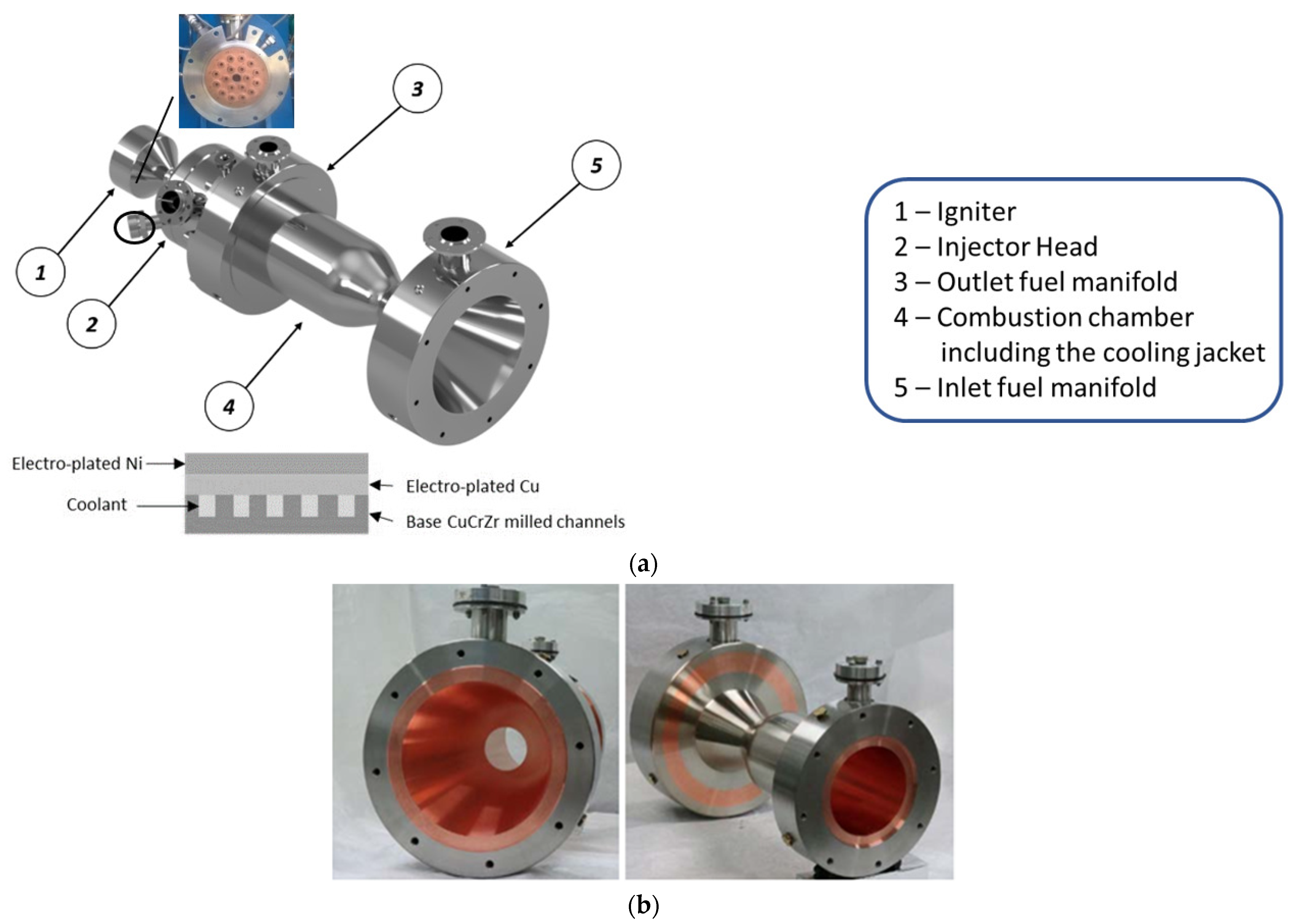
The final HYPROB demonstrator is a 30-kN LOx/LCH4 ground engine, consisting of an actively cooled injector head having 18 injectors, and integrated with a regeneratively-cooled thrust chamber. The thrust chamber includes a cooling jacket, mounted with 96 axial channels. A typical counter-flow architecture has been selected, where the fuel/coolant, liquid methane, enters the channels through the manifold, located in the nozzle region, and exits in the outlet manifold, located in the injector head. Figure 3a shows the model of the assembly, including the most important components, such as the igniter, the injector head, the manifolds, the cooling jacket, and the combustion chamber. The cooling jacket has been realized by means of electrodeposition technology, where the thin copper alloy (CuCrZr) liner of the thrust chamber has been joined to an electroplated layer of pure copper and to the pure nickel close-out. High conductive materials have been selected for the liner and the first deposited layer, while pure nickel provides improved mechanical resistance to the assembly. The general structure is shown in Figure 3a, whereas the combustion chamber of the DEMO first unit (DEMO-0A), the object of the present investigation, is shown in Figure 3b.
The main nominal engine performance, extracted from DEMO technical specifications, is summarized in Table 1.
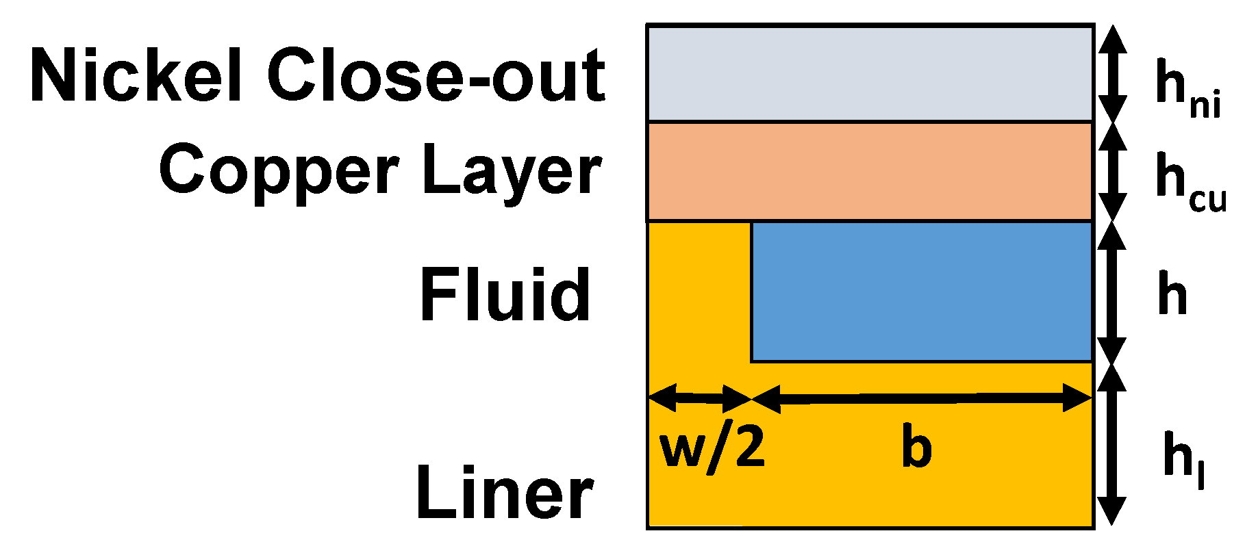
Apart from the igniter, all the components, including the manifolds, the injector head, and the combustion chamber with the cooling jacket, were designed by CIRA. In particular, the cooling jacket was developed using a one-dimensional in-house tool with two-dimensional corrections, which were adopted for the preliminary design activity [47]. Subsequently, the verification of the cooling system performance was accomplished via CFD simulations, using Ansys Fluent [48]. The design strategy involved fixing the number of channels and rib width (w) while changing the rib height (h) in order to obtain the optimized cooling performance at critical sections, where the input heat flux was representative of nominal conditions. Subsequently, three key sections were identified: the end of the nozzle, the convergent-throat, and the cylindrical region where the passage height (which changes linearly over them) was defined. Figure 4 and Figure 5 show the main geometrical parameters.
The non-dimensional geometric parameters considered, based on reference length, L (the overall thrust chamber length), are given below:
  • the height of channels (h/L), ranging from 0.0018 to 0.0061
  • the width of channels (b/L) ranging from 0.0019 to 0.0107
  • the width of ribs (w/L) equal to 0.0032
  • the thickness of the liner (h1/L) equal to 0.0020
  • the height of the copper layer (hcu/L) equal to 0.0023
  • the height of the nickel close-out layer (hni/L) equal to 0.0034
The results are determined via data reduction using typical non-dimensional parameters, such as the Reynolds, Nusselt, and Prandtl numbers together with non-dimensionless variables, including temperature, density, viscosity, thermal conductivity, and specific heat. The associated equations are given below:
R e = ρ u a v d h μ
N u = q ˙ d h ( T w T b , f ) λ f
P r = μ c p λ
T * = T T c r
P * = P P c r
where; uav is the average velocity, dh is the hydraulic diameter of the channel, and q ˙ is the heat flux evaluated on the channel surface. Moreover, Tw and Tb,f are the channel surface temperature and the fluid bulk temperature, respectively, ΔP is the pressure difference, while Tcr and ρcr are the temperature and density referred to the critical point of methane, respectively. In addition, cp, in, λin, and μin represent the fluid specific heat, thermal conductivity, and viscosity, evaluated at the inlet section.

3. Numerical Procedures

The numerical analyses supporting the verification of thermal and fluid-dynamic performances of the cooling jacket were performed by means of ANSYS Fluent v17 [48], considering a single cooling channel of the DEMO-0A configuration. The governing equations, including continuity, momentum, and energy in three-dimensional form were solved under the hypotheses of steady state, the NIST real gas model, and turbulent flow conditions, where the k-ω sst turbulence model was chosen [49]. The thermo-physical properties of methane were taken as a function of temperature and pressure and evaluated from the REFPROP v7.0 database [50]. A steady-state solution was considered, and a segregated pressure-based method was chosen to solve the governing equations. The coupling of the energy and momentum equations was accomplished through a second-order upwind scheme, while, for pressure and velocity, SIMPLEC coupling was chosen [48]. Conduction effects, as well as the roughness of the surfaces of the cooling channels, were also accounted for. All the solid parts associated with the cooling system were included in the numerical domain, whereas, for the modelling of the wall roughness, the set-up of the numerical procedure and mesh generation were accomplished following the procedure described in [48]. Simulations were considered converged if the residuals of the velocity components and energy resulted values dropped below 10−6 and 10−8, respectively, and the steady state regime was attained when the outlet pressure, the outlet fluid temperature, and the maximum wall temperature reached steady state values.
The methane fluid temperature, pressure, and single-channel mass flow rate at the inlet section were used for the initialization of simulations: their nominal values (point N), being set to 110 K, 16.0 MPa, and 0.02 kg/s (overall mass flow rate is equal to 1.92 kg/s), respectively. Additionally, certain off-nominal conditions, defining the DEMO operating box (the points are labelled A, B, C, and D, where N stands for “nominal”), were considered to describe the behaviour of the cooling jacket.
The simulations allowed the modelling of both the liquid and the vapour phase, since the NIST real gas model was activated. With these settings, the fluid undergoes a “pseudo-phase change” along the channel, passing from a compressed supercritical liquid to a supercritical vapour, where trans-critical operating conditions were observed.
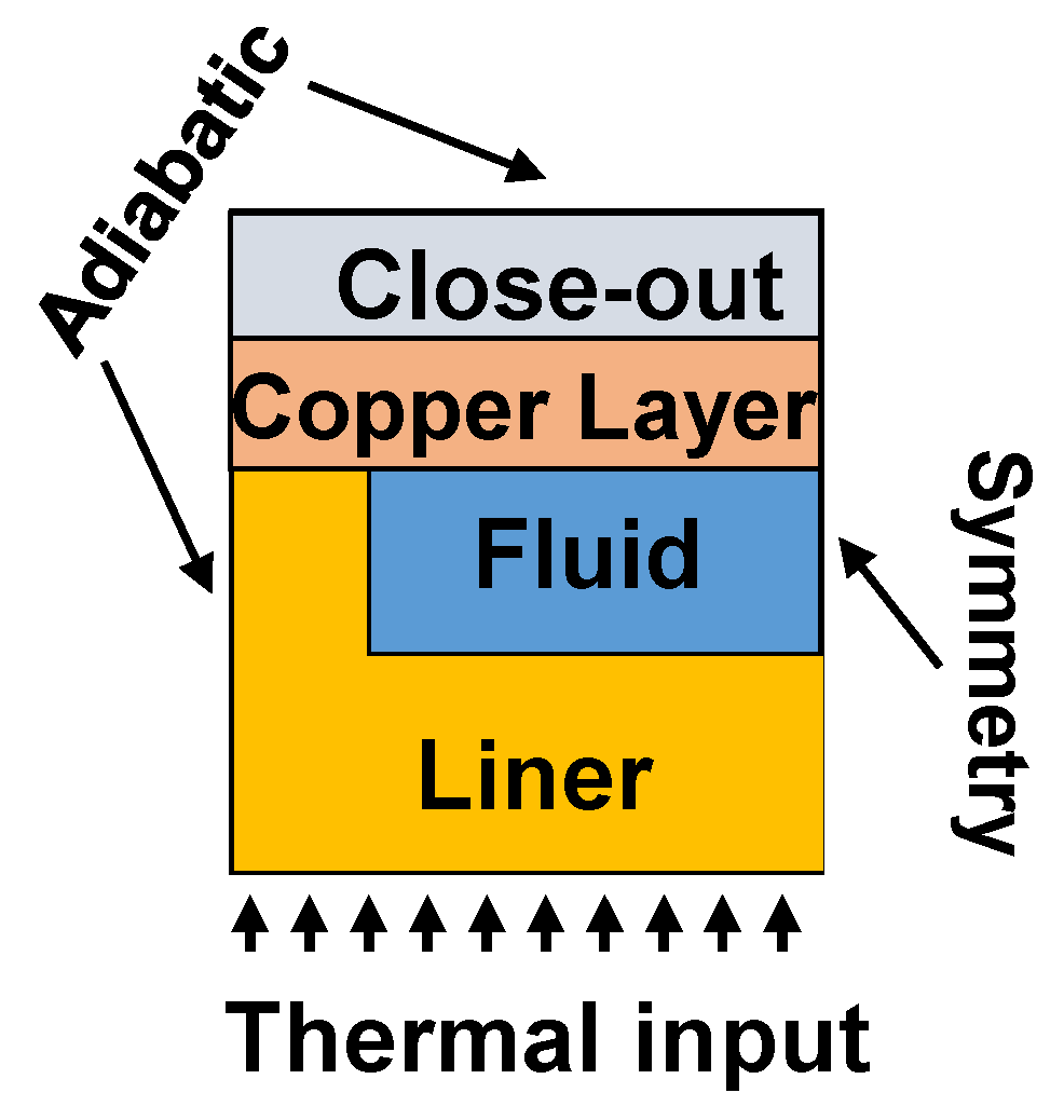
The computational domain also included both solid parts, which consisted of the thrust chamber liner, which was made of CuCrZr copper alloy, while the electrodeposited layer on the rib surface was made from pure copper and, for the close-out, pure nickel was used (see Figure 6). All the thermo-physical properties were considered as a function of temperature and evaluated by means of specific activities associated with material thermo-mechanical characterization via a dedicated characterization activity [51], in line with data cited in the literature [52]. Because a symmetrical model has been considered, only half the channel has been simulated in order to limit the computational effort. The following boundary conditions have been applied, see Figure 6 and Figure 7:
-
inlet section: uniform velocity (at a fixed mass flow) and temperature profiles
-
outlet section: static pressure outlet value
-
channel surfaces: velocity components equal to zero
-
liner surface: input heat flux profiles, as depicted by Figure 7;
-
top and side surfaces: adiabatic
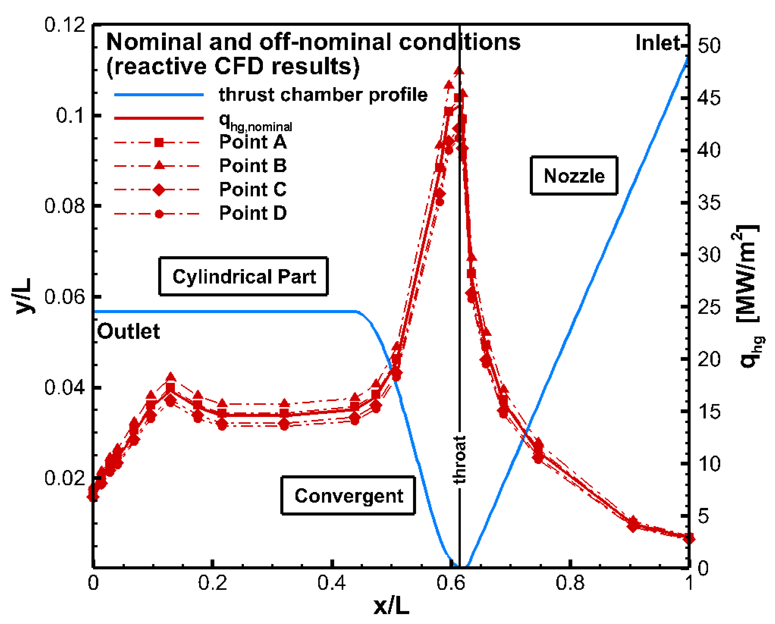
On the liner surface, a heat flux profile is applied in order to account for the heat load coming from the hot side of the combustion chamber. Figure 7 shows information associated with the input heat fluxes for all the working points indicated in Table 2. Apart from the nominal heat flux, adopted for design purposes, several other profiles (points A, B, C, and D) within the operating envelope of the engine were also considered to gain a fuller understanding of the complete cooling jacket behaviour. The heat flux data were obtained from reactive flow simulations of the DEMO combustion chamber, where the wall temperature was set to 300 K [53]. This choice is linked to the conservative approach taken in the design strategy to account for margins in the thermal and mechanical requirements.
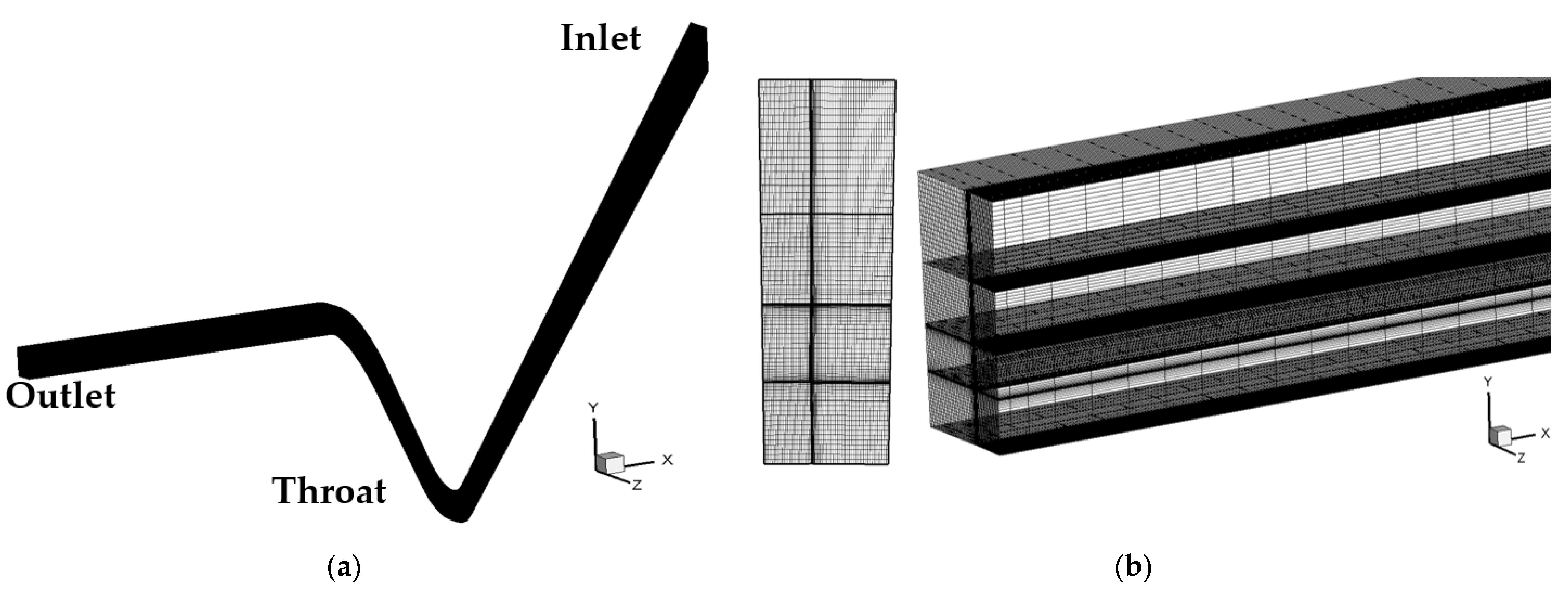
The nominal input heat flux profile, as well as the other nominal parameters, were considered in order to perform mesh sensitivity analysis using three structured meshes, coarse, medium, and fine, having 1.3, 2.7, and 5.6 million points, respectively. Since the channel walls were considered rough, the mesh suggestions reported in Ansys Fluent user’s guide were adopted [48]. The medium mesh was finally chosen because it offered the optimal compromise between computational time and accuracy requirements, as indicated in Table 3. Images showing the distribution of nodes in the axial and transverse directions, as well as the refinement near the channel walls associated with the expansion/contraction sections, are given in Figure 8.

4. Numerical Procedure Validation

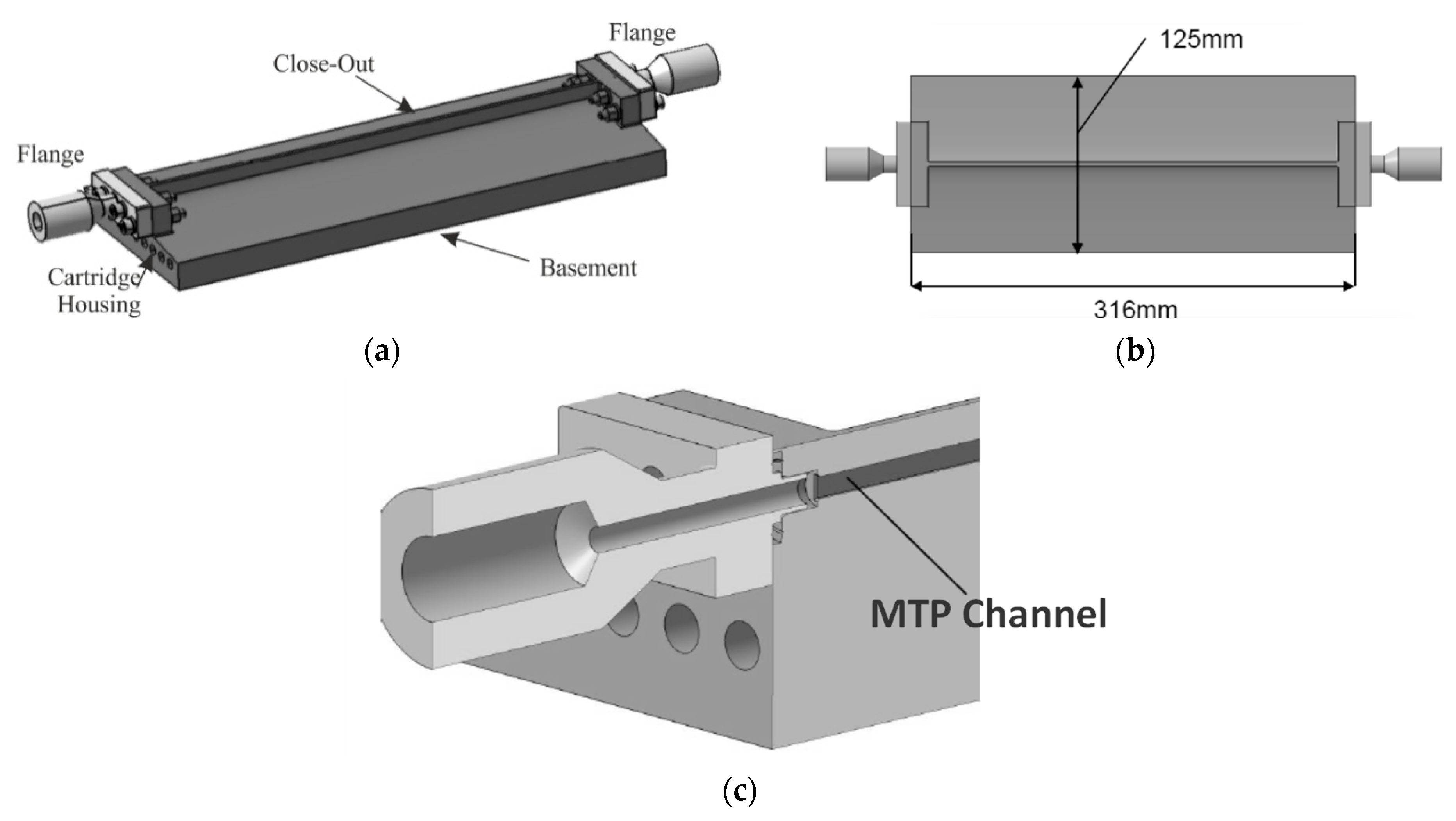
The methodology adopted to simulate the behaviour of the cooling jacket was accomplished through comparisons with the experimental results, obtained by means of an experimental breadboard (MTP-BB [54]), shown in Figure 9. This kind of breadboard was specifically conceived to collect experimental data on the transcritical behaviour inside a typical LRE-like channel configuration. In fact, a narrow axial rectangular channel on the top of the breadboard body was realized, having the dimensions which are comparable to those of the DEMO cooling channels, as shown by Figure 9c, which shows the inlet flange/channel interface. Further information is available in [54]. The copper alloy body accommodates ten electrical cartridges, having a maximum power of about 12 kW, located in specific slots, to ensure that the desired heat flux was representative of that typically experienced in LRE cooling systems for the chosen operating conditions. The test campaign was conducted using the following parameters:
  • inlet mass flow rate ranging from 0.015 to 0.025 kg/s
  • outlet pressure ranging from 8.0 to 15.0 MPa
  • inlet fluid temperature ranging from 120 to 140 K
  • electrical power = 0 (cold flow), 12 kW.
The subsequent numerical rebuilding activity, conducted to validate the numerical procedures and results in terms of fluid temperature, pressure drops, and channel wall temperature values, was in good agreement with the experimental data [54]. The maximum differences in fluid outlet temperature and overall pressure drops were equal to about 1.3% and 4.2% respectively, while the maximum discrepancy of the top or bottom channel wall temperatures was about 1.5%, as indicated in Table 4. Further comparisons between numerical and experimental results for pressure, fluid temperature, and solid wall temperature (at a distance of 4 mm from MTP-BB channel bottom surface) are given in Figure 10 for a range of hot tests. Further information on the activities, procedures, and results is reported in [54].

5. Results and Discussion

Table 5 includes results for numerical simulations, both for the nominal operating conditions of the DEMO-0A cooling jacket (Tin,f = 110 K, Pin = 16.0 MPa and overall m = 1.92 kg/s, corresponding to 0.02 kg/s for each cooling channel), indicated in Table 2, as well as additional working points defining the perimeters of the HYPROB DEMO operating box.
The results refer to the axial profiles given for the liner and channel bottom wall. The fluid variables presented are bulk temperature, static pressure, local and average convective heat transfer coefficient values, and local and average Nusselt number values. The most significant results for the thermo-physical properties are also reported. Finally, plots of the temperature fields, highlighting the transversal slices of significant interest, are also included in order to make comparisons between the various different DEMO working conditions.
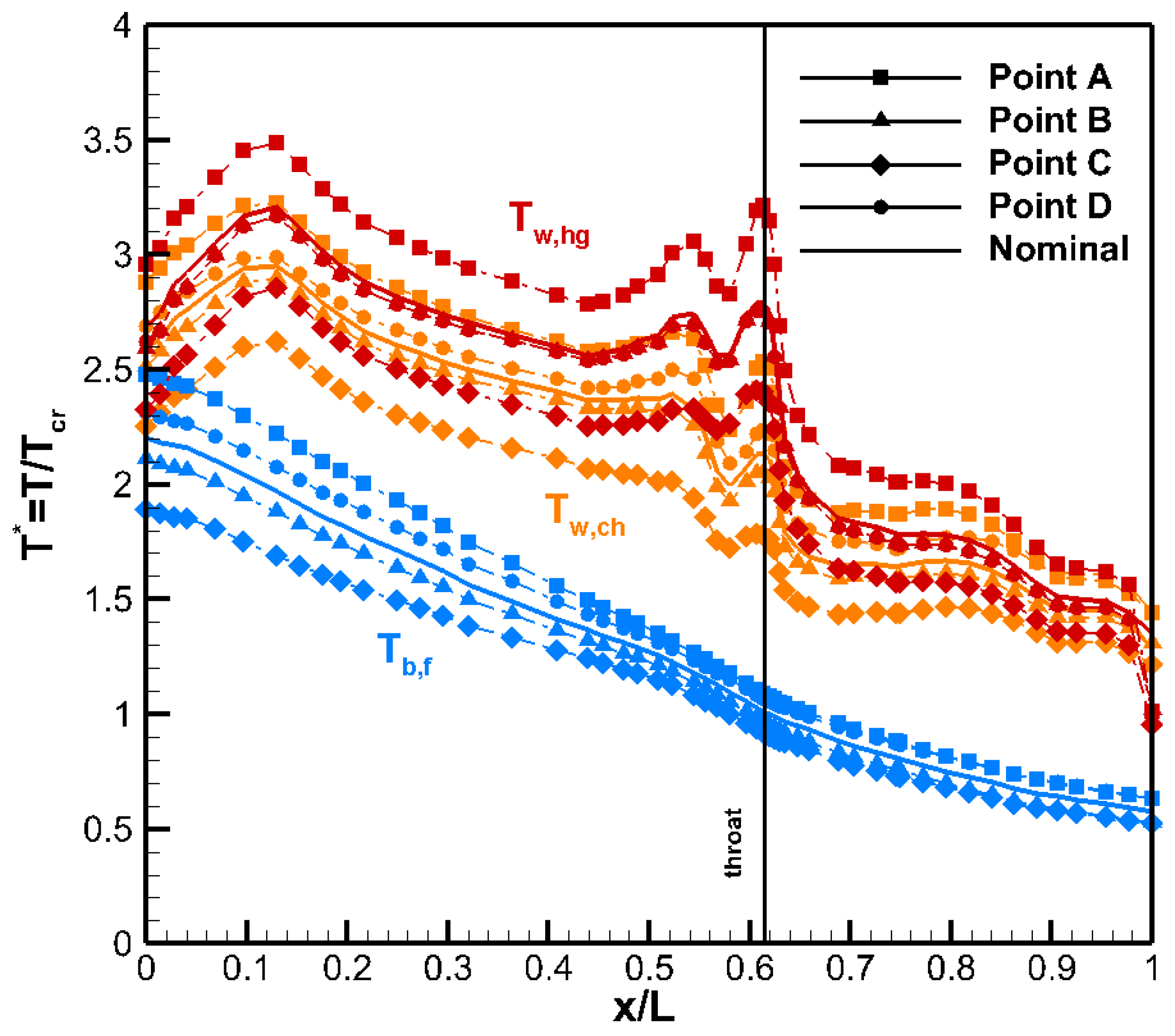
Figure 11 summarizes the results for the axial profile temperature distributions on the hot gas wall and channel bottom, as well as the fluid bulk temperature for the nominal working point, together with additional points limiting the engine operative box. The liner temperature, (Tw,hg) and bottom channel wall temperature (Tw,ch) profiles exhibit three relative maxima in correspondence with the throat (x/L = 0.61), in the convergent region at about x/L = 0.52 and at the re-attachment zone of combustion gases on the chamber walls at x/L = 0.13, where the highest values are attained. In the convergent region, pseudo-critical conditions are observed. In particular, for the nominal working conditions, the hot gas wall temperature Tw,hg maxima reach dimensionless temperature T* values of about 2.8, 2.7, and 3.2 and distances of x/L = 0.61, 0.52, and 0.13, respectively. The most stressed working conditions are at Point A and, indeed, T* is equal to about 3.25, 3.1, and 3.5 at the aforementioned locations, whereas the lowest values are exhibited by Point C, where T* is equal to about 2.5, 2.4, and 2.8, with an overall reduction of more than 20%. Point C is characterized by the most favourable set of working parameters, since the inlet temperature is the lowest considered, and the inlet pressure and the mass flow rate of the refrigerant are the highest. This is seen from the fluid bulk temperature profiles where ∆(T*) between inlet and outlet is equal to 1.3 compared to 1.5 and 1.7 for nominal working point and Point C, respectively, as a consequence of the lower thermal energy transferred from the hot gas side. However, all the profiles show similar trends: in the nozzle region, a liquid-like behaviour can be observed, whereas, at the end of the convergent region, the temperature increases more linearly, changing the slope in proximity of the throat region, where methane begins to locally change its conditions from a “liquid-like” to a “gas-like” fluid, where it exhibits a trans-critical behaviour. In fact, methane enters the cooling system jacket as a compressed liquid and reaches the critical temperature approximately in the throat region. From this section, the refrigerant tends to behave like a highly compressible fluid near the bottom hotter wall of the channel and as a liquid near the upper colder wall. Finally, the profiles change slope at the beginning of the cylindrical region and seem to increase almost linearly. In fact, as the fluid flows towards the exit, larger fractions show vapour-like behaviour over the entire section of the channel until all the refrigerant reaches supercritical gas conditions, since temperature and pressure are much higher than the critical values (T* ranges from 1.9 to 2.5 at the exit).
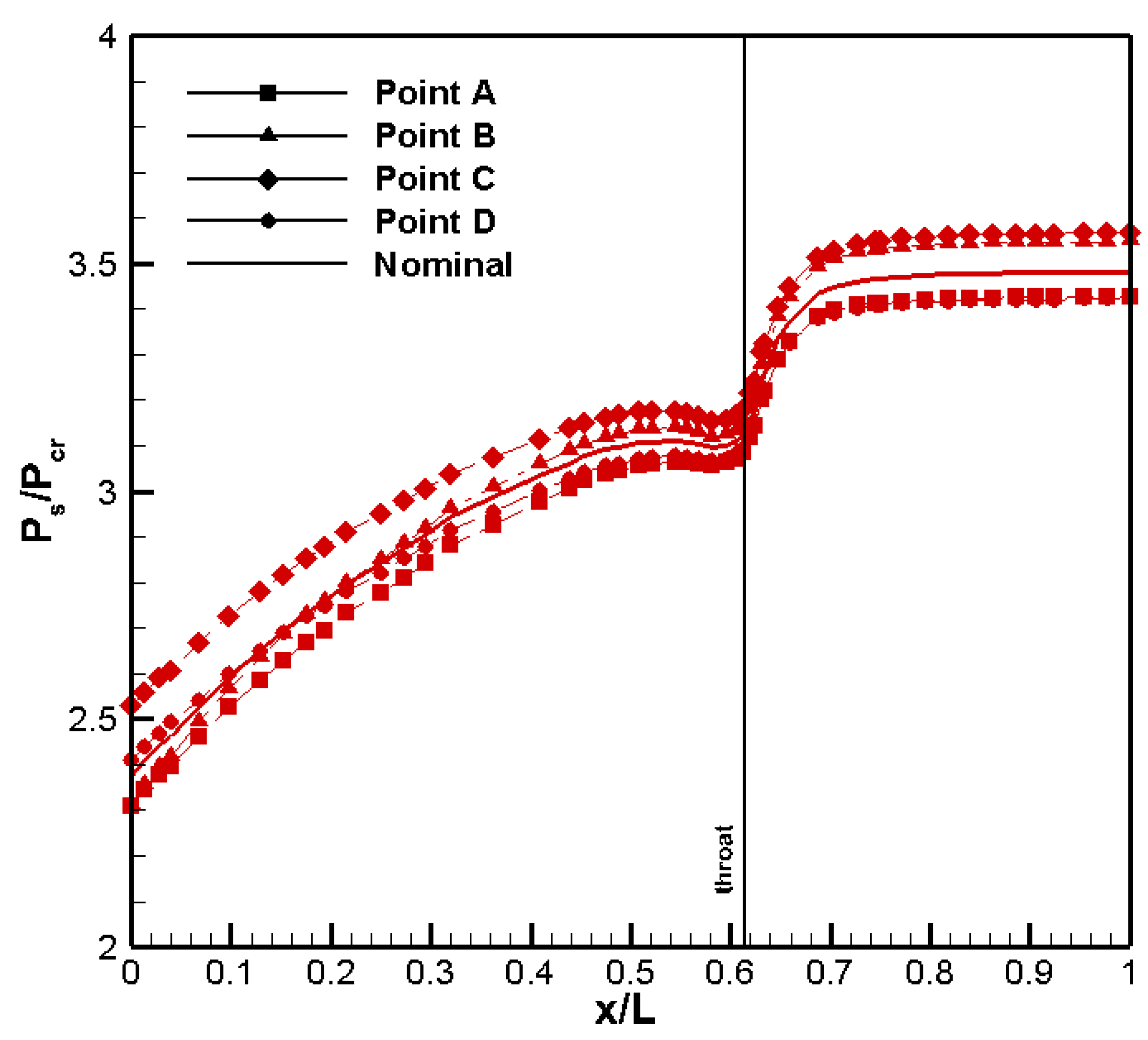
The different behaviour of the working fluid can be analysed by considering the static pressure profiles, shown in Figure 12. Up to x/L = 0.70, the pressure drops are negligible because, in the widest part of the nozzle region, methane remains in the liquid phase. Then, a dramatic decrease in pressure is observed up to the throat because of the changes in the thermo-physical properties and geometric features of the channel. Finally, the pressure drops increase very significantly in the last part of convergent region and, above all, in the cylindrical regions, because the density tends to decrease very rapidly, and the velocity increases towards the outlet section. Depending on the working point, ∆(Ps/Pcr) ranges from 0.9 at Point C to 1.2 at Point A, while, for nominal conditions, it is equal to about 1.0.
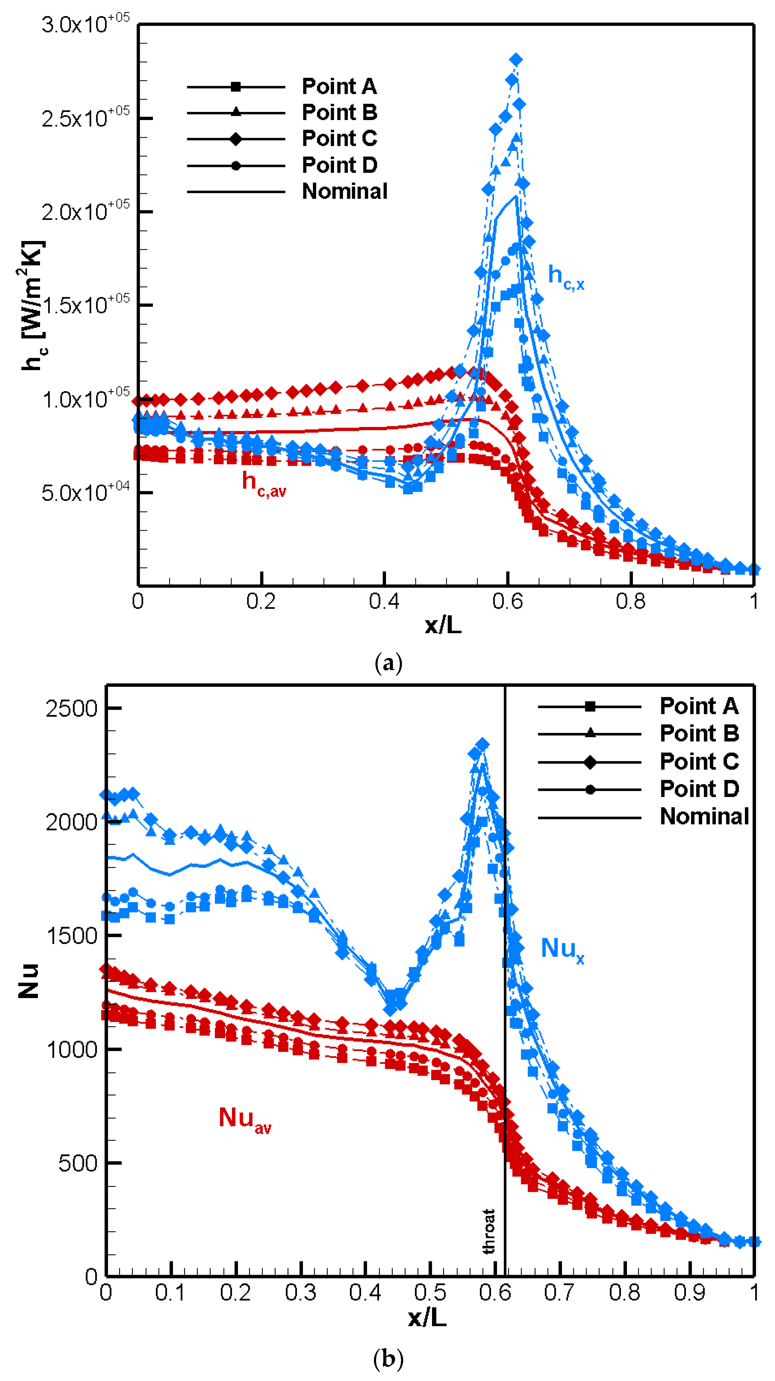
Figure 13 shows the local and average profiles of convective heat transfer coefficients (Figure 13a—( h c , a v = 1 n 1 n h c , x ( i ) ) and Nusselt number (Figure 13b—( N u a v = 1 n 1 n N u x ( i ) ) along the cooling system. The convection heat transfer coefficients tend to increase from the inlet section and reach the highest values at the throat, in line with design phase choices. The hc,x values remain very high around the throat section, and then they drop to a local minimum at x/L = 0.45 before rising again towards x/L = 0. Although methane is in supercritical vapour conditions, the density continues reducing through the cylindrical region, and the velocity increases towards the exit. The highest values of convection heat transfer coefficients are detected for the Point C working conditions, with an increase of 33% compared with the nominal conditions. The reasons are linked to the inlet conditions of the fluid, where the temperature and mass flow rate are 9% lower and 1.09 higher than those of the nominal working point, respectively. The lowest values of hc,x in the throat region are attained for point A, having a peak of about 75% that of the peak at x/L = 0.61 for the nominal conditions.
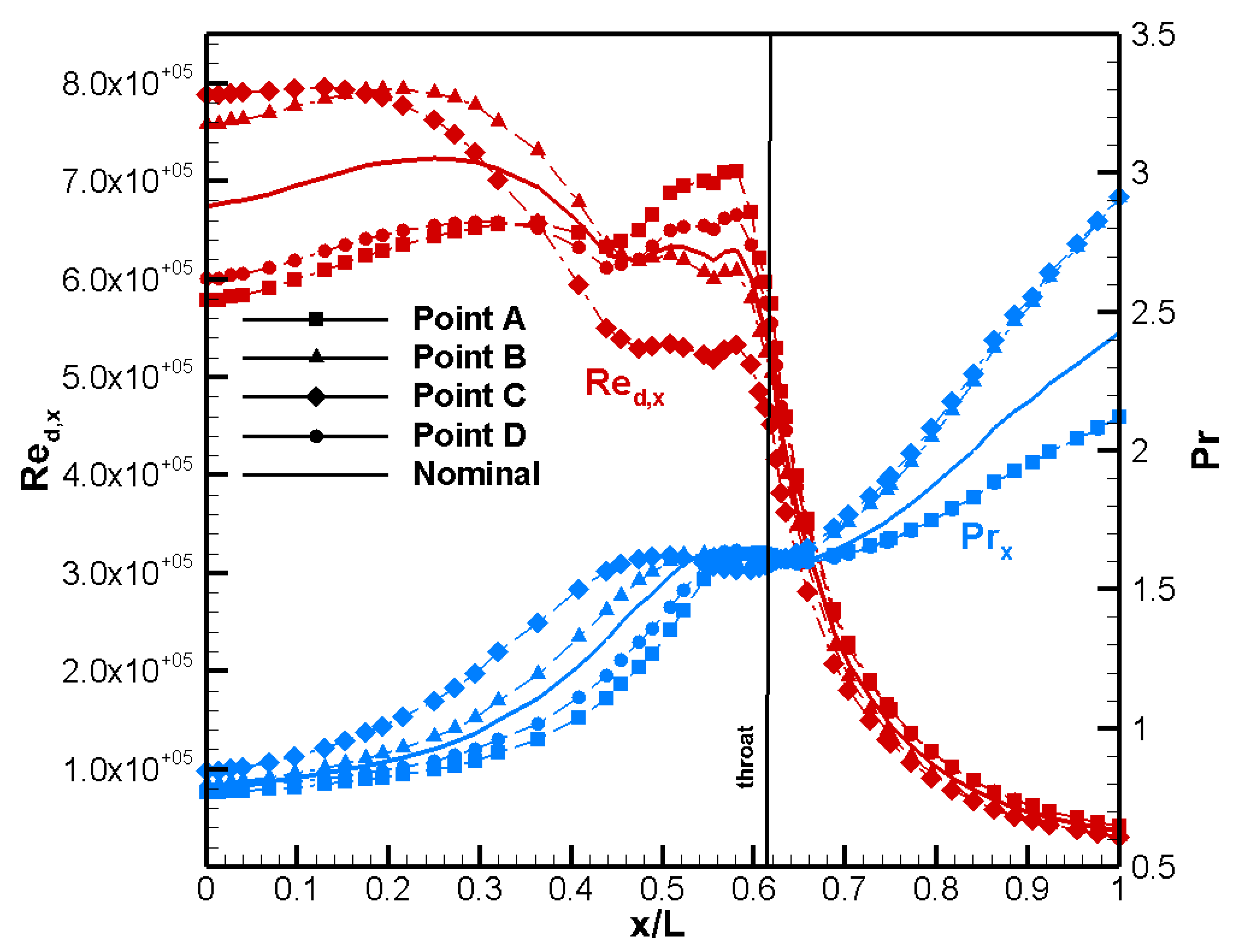
Figure 13b shows the Nusselt number profiles. The minimum values are greater than 200 since the flow regime is fully turbulent, as indicated by the Reynolds number profiles shown in Figure 14. The peaks are located slightly upstream of the throat at x/L = 0.56, where a relative maximum of Reynolds number is also observed. The reason for this behaviour is that, whilst the dimension of the channel is comparable to the throat section, as are the heat transfer coefficient and velocity distributions, the thermal conductivity and density rapidly reduce in the first part of the convergent region, which will be discussed subsequently. Beyond the throat region, as x/L = 0 is approached, the Nusselt number profiles increase towards the outlet where the fluid is very hot, and the fluid velocity increases.
Regarding the Reynolds number, shown in Figure 14, methane is injected as a compressed liquid in the turbulent regime, and the Reynolds number increases from the inlet section towards x/L = 0.70, rising to a maximum in the throat region. This is linked to the changes in thermo-physical properties and the geometric parameters adopted when designing the cooling channels (the cross-sectional area is a minimum at the throat). Beyond x/L = 0.56, the Reynolds number remains very high and subsequently increases towards the exit, where the refrigerant has become a supercritical vapour. The maximum values of Reynolds number are obtained for the Point B and C working conditions. The Prandtl number profiles clearly show the different behaviour of methane within the cooling system. Typical values, comparable to liquid, are evident in the inlet and divergent region. The Pr ranges from 2.1 to 2.9, depending on the inlet conditions of the associated operative points. The Prandtl decreases very rapidly and reaches a sort of a plateau (Pr is equal to about 1.5) near the throat where average critical temperature is reached. From the middle of the convergent region the Pr tends to decrease to values typical of the gaseous phase, being about 0.7.
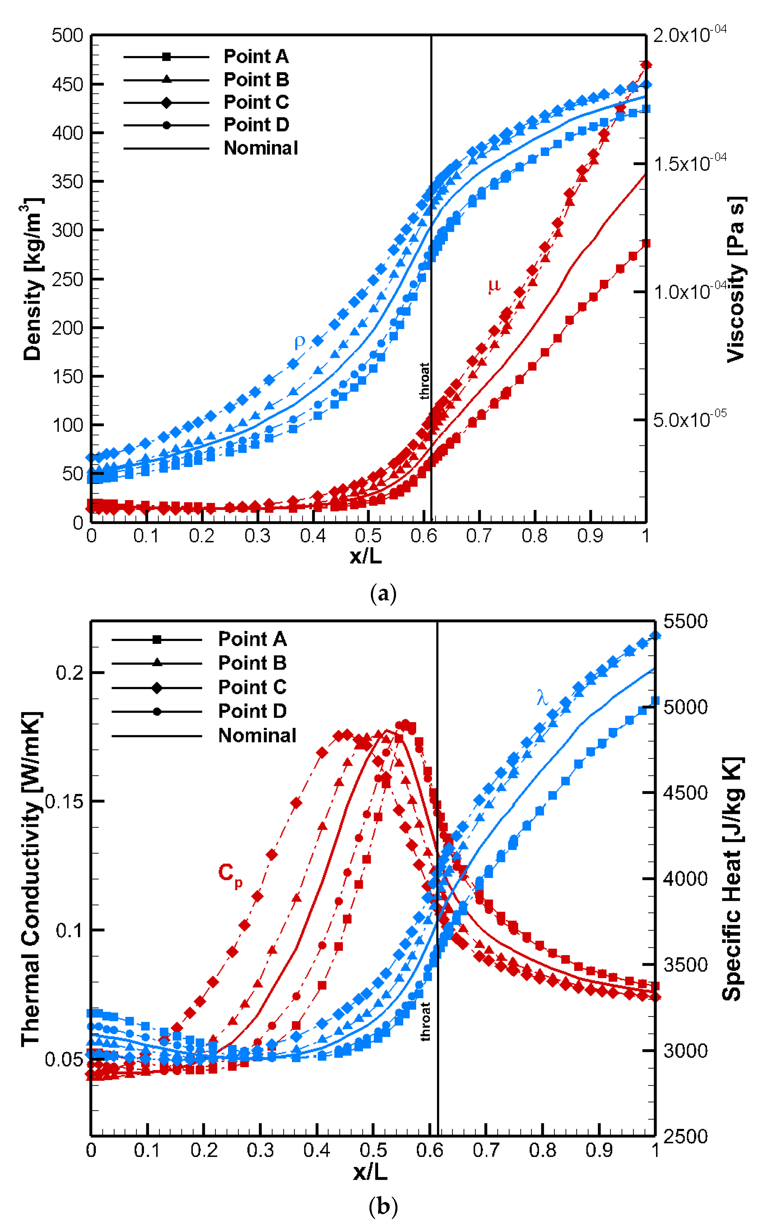
The axial profiles of the most significant thermo-physical properties, including density, viscosity, specific heat, and thermal conductivity, allow a fuller understanding of methane behaviour inside the cooling system. Figure 15 shows the monotonic decrease in density, viscosity, and thermal conductivity, together with a small increase in λ beyond x/L = 0.3. This agrees with the literature data for the fixed temperature/pressure couple [50]. All these properties reduce by about one order of magnitude from inlet to outlet. For Points C and D, characterized by the lowest inlet temperature and highest inlet pressure and mass flow inlet, the decrease in density and viscosity is slightly less evident. In the convergent-throat-divergent zones, near critical conditions are attained and, thus, variations are more significant, in particular around the throat section. The viscosity tends to decrease in the first part of the divergent region, while the density and thermal conductivity appear to be less affected by the change in spatial location. In the cylindrical region, the trans-critical behaviour of methane, where the fluid flows as supercritical vapour, is evident, and the density and thermal conductivity remain almost constant [55]. The specific heat, shown in Figure 15b, has maxima lying over a range of positions from x/L = 0.42 to 0.54, which are associated with average pseudo-critical conditions and depend on the inlet conditions and input heat flux imposed by the points considered in the limiting box. In particular, as discussed in [56], the inlet temperature plays an important role, and, if it is increased, the maximum of the specific heat capacity distribution moves in the throat direction and attains higher values, as shown by the results associated with Points A and D. Comparing the temperature axial profiles and results for the specific heat, the deterioration mode, described by several authors in the literature [55,57,58,59] in the DEMO operative box, is absent since the temperatures in the vicinity of the pseudo-critical point are controlled and maintained below throat and re-attachment point section values. This is due to the care taken in the design phase to avoid this phenomenon by defining suitable geometric features and the choice of surface roughness [60].
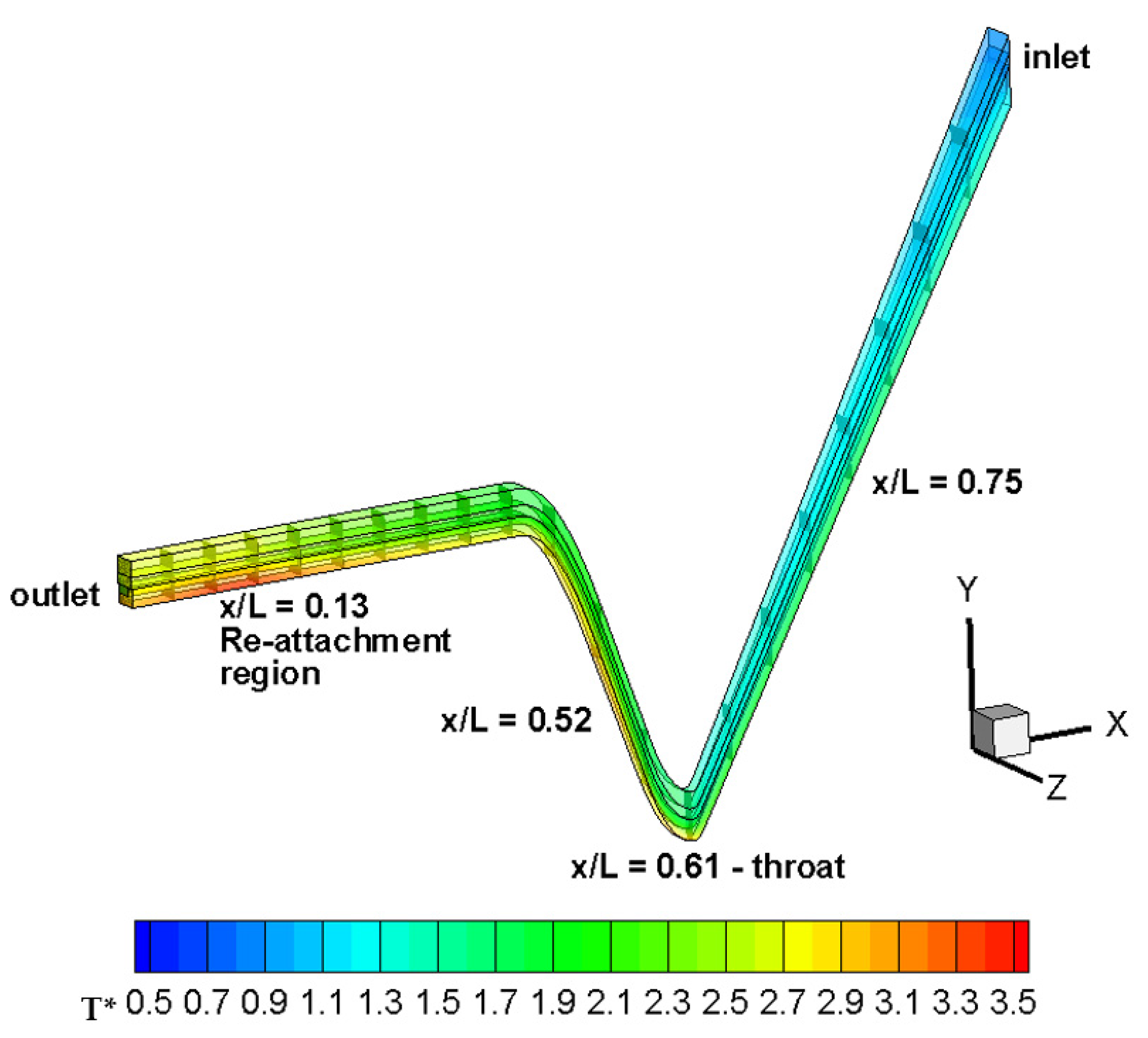
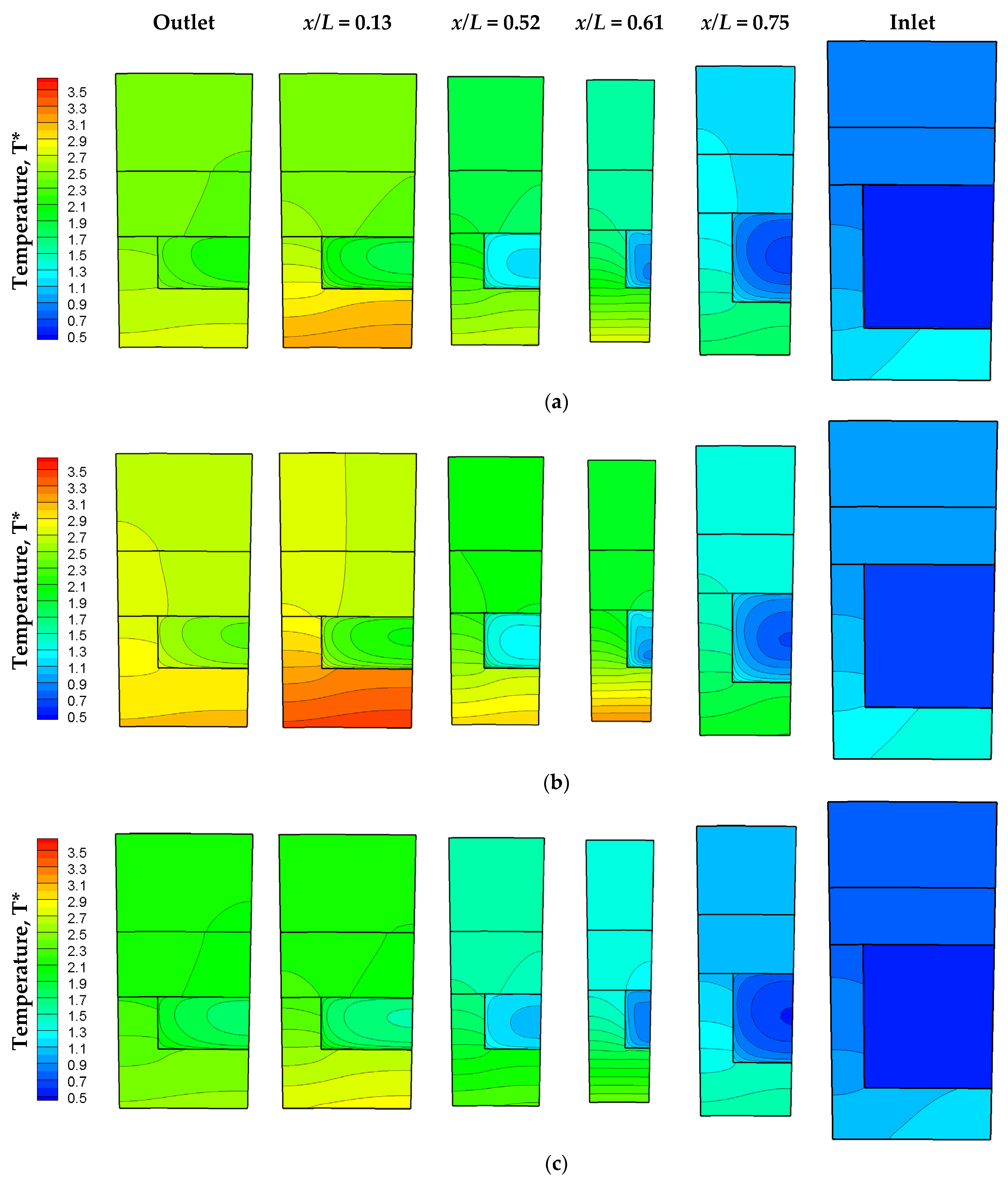
Figure 16 illustrates the most thermally stressed regions interpreted through the dimensionless temperature fields, taken at nominal working conditions. Some significant transversal slices are shown: outlet (x/L = 0.00); re-attachment point region (x/L = 0.13); a section where the pseudo-critical conditions inside the channel are observed on average (x/L = 0.52); the throat (x/L = 0.61); and a section associated with the divergent region (x/L = 0.75) and the inlet (x/L = 1.00). These slices are detailed in Figure 17, and the temperature fields illustrate the thermal stratification inside the channel and the evident difference of temperature exhibited by the walls exposed to the combustion gases (the liner) and the bottom walls of the channel with respect to the top walls, which remain at very low values since the refrigerant enters the cooling system as a compressed liquid (x/L = 1.00). The structure remains only slightly thermally stressed up to x/L = 0.75, also for working Point A, as shown in Figure 17b, and the field keeps almost homogeneous in the copper and nickel close-out layers. The fluid attains the critical value in the throat region (x/L = 0.61), on average, but a significant gradient near the bottom wall is evident for x/L = 0.75. In fact, in the divergent region, methane starts to show transcritical conditions, since, as the bottom walls of the channel are approached, the fluid tends to reach the critical temperature. The thermal stratification [61,62,63] is so significant that methane behaves similar to a gas-like fluid near the channel bottom wall and side (this is particularly evident for the throat slice) and similar to a liquid-like fluid near the top surface of the channel. For Point A conditions, large parts of the fluid have already undergone the pseudo-change of phase to vapour (Figure 17b), while, for Point C, the liquid core is very large and noticeable particularly at the x/L = 0.61 section. For Point C, at x/L = 0.52, there is a large cold bubble inside the channel, see Figure 17c, yet, at the nominal working conditions and Point B, the larger sections behave similar to a gas. In this vicinity, pseudocritical conditions are reached, but, although the specific heat attains its maximum values and thermal conductivity attains its minima, no overheating phenomena are detected, even under the most extreme conditions, indicated by Point A. In fact, no significant thermal barriers are observed, and temperature values (T*) of the liner increase to a maximum value about 3.0. These temperature peaks are typical of LRE liners and widely within the maximum allowable values for CuCrZr materials. Depending on the mechanical loads, temperatures in the range of 700 K–900 K (corresponding to T* in the range of 3.7–4.7) are acceptable for the materials adopted [64]. On approaching the exit, from the convergent zone, the refrigerant tends to behave completely as a gas-like fluid, as shown by the x/L = 0.13 and 0.0 slices. In particular, at x/L = 0.13, the maximum values of the liner temperature are attained, although they are far from the material limits and design constraints (T* = 3.5 for Point A conditions) due to the very high fluid velocity (low density values) and consequent relatively high values of convective heat transfer coefficients.
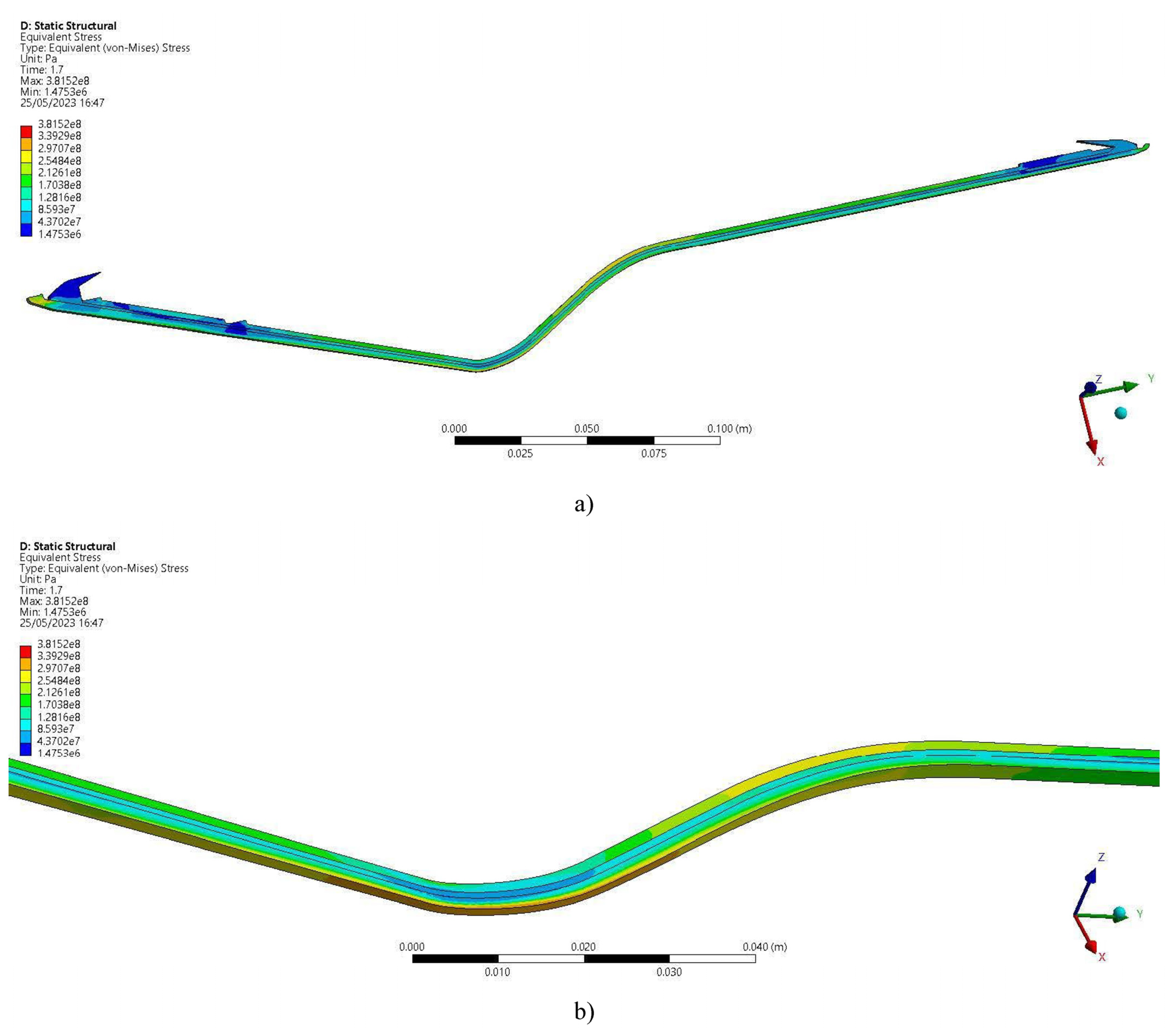
The results, obtained through detailed CFD analyses, have been useful to perform the subsequent thermo-structural verifications. Figure 18 shows the equivalent von Mises stress results, considering the whole thrust chamber Figure 18b gives details on the throat zone. The most critical conditions occur in the throat area, where high heat fluxes and high thermal gradients in the ligament thickness are expected.
However, those values are not critical since no significant plastic strain occurs in the first cycles. Furthermore, it appears that thermal ratcheting represents the main damage mechanism, since plastic strain accumulates cycle after cycle in the throat region. However, the expected number of cycles to failure is very high, more than 100. More information about the models and procedures adopted is given in [65,66].

6. Conclusions

The thermal and fluid-dynamics analyses, accomplished to support the design and development of HYPROB DEMO-0A 30-kN thrust class engine, based on liquid oxygen/liquid methane couple, have been presented and discussed. Both the refrigerant behaviour, which exhibits transcritical issues, and the cooling jacket response, are described. Results have been adopted as input for the thermo-structural investigations, necessary to estimate the design margins and life cycle of the engine before accomplishing the manufacturing and consequent firing tests. The final successful experimental campaign has confirmed the robustness of the design.
The numerical simulations have been conducted, considering all the points limiting the operative box of the engine beyond the nominal working conditions. In this way, a different set of parameters, represented in terms of inlet temperature, pressure, and mass flow rate (and consequently, input heat flux), have been studied. Consequently, a complete examination of methane behaviour and cooling jacket response in “typical” working conditions has been conducted.
First of all, it is important to emphasize that, also in the most extreme working conditions, no overheating phenomena were detected, even when pseudo-critical conditions were reached. The maximum temperature values were attained in the throat section, where the peak of heat flux was located (x/L = 0.61), and in correspondence with the reattachment point region (x/L = 0.13) for all the operative points considered. In particular, at x/L = 0.13, the thermal control is more delicate, since a relative maximum of heat flux is observed, and methane acts as a supercritical vapour, characterized by poor thermal properties, but high velocity. In a regeneratively cooled liquid rocket engine, the cryogenic propellant undergoes a pseudo-change of phase from a compressed supercritical liquid to a supercritical vapour during its flow inside the cooling system. In the present engine, the critical temperature is reached on in the throat region, but some fractions of the refrigerant tend to show near-critical conditions or even gas-like behaviour already from x/L = 0.75. This can be seen at nominal working conditions and particularly if Point A is considered. Indeed, the thermal stratification inside the channel is most evident if point A conditions are applied. For point C, large parts of cold fluid are observed, even in the throat region, since the inlet conditions are the most favourable in terms of lowest inlet temperature and highest inlet pressure and mass flow rate. For this working point, also, the highest values of heat transfer coefficients (and Nusselt number) were calculated and located in the throat zone. However, the convective heat transfer coefficients also remain quite high in the convergent region, where pseudo-critical conditions are attained. This implies no evident deterioration mode for all the working points considered.

Author Contributions

Conceptualization, D.R., F.B. and M.F.; methodology, D.R., F.B. and M.F.; software, D.R.; validation, D.R.; formal analysis, D.R. and F.B.; investigation, D.R. and F.B.; data curation, D.R., F.B. and M.F.; writing—original draft preparation, D.R., F.B. and M.F.; writing—review and editing, D.R., F.B. and A.D.F.; visualization, D.R.; supervision, F.B.; project administration, F.B. All authors have read and agreed to the published version of the manuscript.

Funding

Italian Ministry of University and Research: Progetto MIUR - FESR P.O 1994/1999- Realizzazione del programma di propulsione.

Data Availability Statement

Not applicable.

Acknowledgments

This work was accomplished in the framework of HYPROB Project, financed by the Italian Ministry of University and Research. The authors would like to thank all the involved colleagues and, in particular, Pasquale Natale, Michele Ferraiuolo and Daniele Cardillo, for their appreciated precious efforts and cooperation in all the phases of the project.

Conflicts of Interest

The authors declare no conflict of interest.

Nomenclature

AArea [m2]
AMAdditive Manufacturing
bWidth of the cooling channel [m]
BBBreadBoard
CFDComputational Fluid-Dynamic
ELVExpendable Launch Vehicle
cpSpecific heat [J/ kg K]
dDiameter [m]
DEMODemonstrator
fFriction factor [-]
FTFiring Test
hHeight of the cooling channel [m]
hcConvective heat transfer coefficient [W/ m2 K]
HYPROBHydrocarbon PROpulsion test Bench
IImpulse [s]
jColburn number [-]
kTurbulence kinetic energy [m2 /s2]
l or LLength of test articles [m]
LCH4Liquid methane
LNGLiquid Natural Gas
LOxLiquid oxygen
LRELiquid rocket engine
mMass flow rate [kg/ s]
m*Mass flow rate referred to nominal operating conditions [-]
MTPMethane Thermal Properties
NISTNational Institute of Standard and Technology
O/FMixture ratio (Oxidizer mass/Fuel mass) [-]
PPressure [Pa]
Pin*Inlet pressure referred to nominal operating conditions [-]
PrPrandtl number [-]
qHeat flux [W/m−2]
RLVReusable Launch Vehicle
RCSReaction Control System
sstshear stress transport
tTime [s]
TTemperature [K]
T*Dimensionless temperature [-]
Tin,f*Fluid inlet temperature referred to nominal operating conditions [-]
wWidth of the rib [m]
x, y, zSpatial coordinates [m]
Greek symbols
λThermal conductivity [W/m K]
μViscosity [Pa s]
ρDensity [kg/m3]
ωSpecific dissipation rate of turbulence kinetic energy [s−1]
Subscripts
avaverage
awadiabatic wall
bbulk
cccombustion chamber
chchannel
crcritical
cucopper
ffluid
hhydraulic
hghot gas side
ininlet
lliner
maxmaximum
ninickel
nomnominal
outoutlet
pcpseudo-critical
sstatic
spspecific
tthroat
wwall

References

  1. Battista, F.; Ricci, D.; Natale, P.; Cardillo, D.; Fragiacomo, M.; Franchitti, S.; Ferraiuolo, M.; Salvatore, V. Recent Achievements regarding the Research Activities on HYPROB LOX/CH4 Demonstrators Line. In Proceedings of the 8th Space Propulsion Conference, Estoril, Portugal, 9–13 May 2022. [Google Scholar]
  2. Musk, E. Raptor V3 just Achieved 350 bar Chamber Pressure (269 tons of Thrust). Congrats to @SpaceX Propulsion Team! Starship Super Heavy Booster has 33 Raptors, so Total Thrust of 8877 tons or 19.5 million Pounds. (Tweet)—Via Twitter. Available online: https://twitter.com/elonmusk/status/1657249739925258240 (accessed on 12 May 2023).
  3. Battista, F.; Ricci, D.; Natale, P.; Cardillo, D.; Fragiacomo, M.; Ferraiuolo, M. HYPROB-New: Recent Developments of the LOX/LCH4 Research Line. In Proceedings of the 7th Space Propulsion Conference, Web Conference, 17–19 March 2022. [Google Scholar]
  4. Hurlbert, E.A.; Ueno, H.; Alexander, L.; Klem, M.D.; Daversa, E.; Rualt, J.-M.; Manfletti, C.; Caruana, J.-N.; Asakawa, H.; Whitley, R.J. International Space Exploration Coordination Group Assessment of Technology Gaps for LOx/Methane Propulsion Systems for the Global Exploration Roadmap. In Proceedings of the AIAA SPACE 2016, Long Beach, CA, USA, 13–16 September 2016. [Google Scholar] [CrossRef] [Green Version]
  5. Komar, D.R.; Moses, R. Hercules Single-Stage Reusable Vehicle supporting a Safe, Affordable, and Sustainable Human Lunar & Mars Campaign. In Proceedings of the AIAA SPACE and Astronautics Forum and Exposition, Orlando, FL, USA, 12–14 September 2017. [Google Scholar]
  6. Schuffet, R.; Maier, M.; Sindiy, O.; Ulrich, C.; Fugger, S. Integrated Modeling and Analysis for a LOx/Methane Expander Cycle Engine: Focusing on Regenerative Cooling Jacket Design. In Proceedings of the 42nd AIAA/ASME/SAE/ASEE Joint Propulsion Conference & Exhibit, Sacramento, CA, USA, 9–12 July 2006. [Google Scholar] [CrossRef]
  7. Brown, C.D. Conceptual Investigations for a Methane-Fueled Expander Rocket Engine. In Proceedings of the 40th AIAA/ASME/SAE/ASEE Joint Propulsion Conference & Exhibit, Fort Lauderdale, FL, USA, 11–14 July 2004. [Google Scholar]
  8. Haeseler, D.; Bombelli, V.; Vuillermoz, P.; Lo, R.; Marèe, T.; Caramelli, F. Green Propellant Propulsion Concepts for Space Transportation and Technology Development Needs. In Proceedings of the 2nd International Conference on Green Propellants for Space Propulsion, Cagliari, Italy, 7–8 June 2004. [Google Scholar]
  9. Ierardo, N.; Cuoco, F.; Accettura, A.; Congiunti, C.; Bruno, C. LOX-Methane Systems for High Thrust LRE. In Proceedings of the 4th International Conference on Launcher Technology, Liege, Belgium, 3–6 December 2002. [Google Scholar]
  10. Li, S.; Zhang, Y.D.; Li, Y.; Liao, R.Q. Equilibrium Calculation and Technological Parameters Optimization of Natural Gas Liquefaction Process with Mixed Refrigerant. Int. J. Heat Technol. 2015, 33, 123–128. [Google Scholar] [CrossRef] [Green Version]
  11. Trejo, A.G. An Experimental Investigation of Liquid Methane Convection and Boiling in Rocket Engine Cooling Channels. Master Thesis, The University of Texas at El Paso, El Paso, TX, USA, 2014. [Google Scholar]
  12. Rajagopal, M. Numerical Modeling of Regenerative Cooling System for Large Expansion Ratio Rocket Engines. J. Therm. Sci. Eng. Appl. 2015, 7, 011012. [Google Scholar] [CrossRef]
  13. Zhang, M.; Sun, B.; Song, J. Effect of Inlet and Outlet Manifolds on Regenerative Cooling in LOX/Methane Thrust Chambers. J. Therm. Sci. 2020, 30, 517–529. [Google Scholar] [CrossRef]
  14. Pizzarelli, M.; Battista, F. Oxygen–methane rocket thrust chambers: Review of heat transfer experimental studies. Acta Astronaut. 2023, 209, 48–66. [Google Scholar]
  15. Khan, T.W.; Qamar, I. Testing Procedure for Laboratory Scale Semi Cryogenic Combustion Chamber of LPRE with Problems Faced and Lessons Learned. J. Therm. Sci. 2022, 31, 2171–2177. [Google Scholar] [CrossRef]
  16. Shin, J.; Roh, T.; Lee, H.J. Comparison of the Semi-empirical Heat Transfer Coefficient for a Liquid Rocket Nozzle with Regenerative Cooling Jacket. J. Propuls. Energy 2022, 3, 51–60. [Google Scholar]
  17. Ebrahimi, A.; Shokri, M. Thermal Behaviour Analysis of Near-critical Cryogenic Fluids in Cooling Channels. Mech. Eng. 2019, 1, 23–31. [Google Scholar]
  18. Shokri, M.; Ebrahimi, A. Heat Transfer Aspects of Regenerative-cooling in Methane-based Propulsion Systems. Aerosp. Sci. Technol. 2018, 82, 412–424. [Google Scholar] [CrossRef]
  19. Hernandez, L.; Palacios, R.; Ortega, D.; Adams, J.; Bugarin, L.; Rahman, M.M.; Choudhuri, A. The Effects of Roughness on LCH4 Boiling Heat Transfer Performance of Conventionally and Additively Manufactured Rocket Engine Regenerative Cooling Channels. In Proceedings of the AIAA Propulsion and Energy 2019 Forum, Indianapolis, IN, USA, 19–22 August 2019. [Google Scholar]
  20. Haermisch, J.; Suslov, D.; Waxenegger-Wilfing, G.; Dresia, K.; Oschwald, M. LUMEN—Design of the Regenerative Cooling System for an Expander Bleed Cycle Engine using Methane. In Proceedings of the 7th Space Propulsion Conference, Virtual Conference, 17–19 March 2021. [Google Scholar]
  21. Waxenegger-Wilfing, G.; Dresia, K.; Deeken, J.C.; Oschwald, M. Heat Transfer Prediction for Methane in Regenerative Cooling Channels with Neural Networks. J. Thermophys. Heat Transf. 2020, 34, 347–357. [Google Scholar] [CrossRef]
  22. Waxenegger-Wilfing, G.; Dresia, K.; Oschwald, M. Machine Learning Methods for the Design and Operation of Liquid Rocket Engines—Research Activities at the DLR Institute of Space Propulsion. In Proceedings of the 7th Space Propulsion Conference, Virtual Conference, 17–19 March 2021. [Google Scholar]
  23. Kajon, D.; Liuzzi, D.; Boffa, C.; Rudnykh, M.; Drigo, D.; Arione, L.; Ierardo, N.; Sirbi, A. Development of the Liquid Oxygen and Methane M10 Rocket Engine for the Vega-E Upper Stage. In Proceedings of the 8th European Conference for Aeronautics and Space Sciences (EUCASS), Madrid, Spain, 1–4 July 2019. [Google Scholar]
  24. Bonhomme, C.; Theron, M.; Louaas, E.; Beaurain, A.; Seleznev, E.P. French/Russian Activities on LOX—LCH4 Area. In Proceedings of the 57th International Astronautical Congress, Valencia, Spain, 2–6 October 2006. [Google Scholar]
  25. Iannetti, A.; Girard, N.; Tchou-Kien, D.; Bonhomme, C.; Ravier, N.; Edeline, E. Prometheus, a LOX/LCH4 Reusable Rocket Engine. In Proceedings of the 7th European Conference for Aeronautics and Space Sciences (EUCASS), Milan, Italy, 1–6 July 2017. [Google Scholar]
  26. Simontacchi, P.; Blasi, R.; Edeline, E.; Sagnier, S.; Ravier, N.; Espinosa-Ramos, A.; Breteau, J.; Altenhoefer, P. Prometheus: Precursor of New Low-cost Rocket Engine Family. In Proceedings of the 8th European Conference for Aeronautics and Space Sciences (EUCASS), Madrid, Spain, 1–4 July 2019. [Google Scholar]
  27. Flock, A.; Underhill, K.; Caruana, J.N. Innovations in Propulsion within ESA’S Future Launcher Preparatory Programme (FLPP) Advanced Technology. In Proceedings of the 8th Space Propulsion Conference, Estoril, Portugal, 9–13 May 2022. [Google Scholar]
  28. Deeken, J.; Waxenegger-Wilfing, G.; Oschwald, M.; Schlechtriem, S. Lumen Demonstrator—Project Overview. In Proceedings of the 32nd International Symposium on Space Technology and Science, Beppu, Japan, 26 February–4 March 2019. [Google Scholar]
  29. Traudt, T.; Börner, M.; Suslov, D.; Dos Santos Hahn, R.H.; Saraf, A.M.; Klein, S.; Deeken, J.C.; Hardi, J.; Oschwald, M.; Schlechtriem, S. Liquid Upper Stage Demonstrator Engine (LUMEN): Component Test Results and Project Progress. In Proceedings of the International Astronautical Congress 2022, Paris, France, 18–22 September 2022. [Google Scholar]
  30. Russian Space Agency Launches Work to Develop Rocket with Methane Propellant Engine. Available online: https://tass.com/science/1178475 (accessed on 27 April 2023).
  31. Asakawa, H.; Nanri, H.; Aoki, K.; Kubota, I.; Mori, H.; Ishikawa, Y.; Kimoto, K.; Ishihara, S.; Ishizaki, S. The Status of the Research and Development of LNG Rocket Engines in Japan. In Chemical Rocket Propulsion; Springer: Berlin/Heidelberg, Germany, 2017; pp. 463–487. [Google Scholar]
  32. Ukai, S.; Sakaki, K.; Ishikawa, Y.; Sakaguchi, H.; Ishihara, S. Component Tests of a LOX/Methane Full Expander Cycle Rocket Engine: Injector and Regeneratively Cooled Combustion Chamber. In Proceedings of the 8th European Conference for Aeronautics and Space Sciences (EUCASS), Madrid, Spain, 1–4 July 2019. [Google Scholar]
  33. Space Walker. Available online: https://www.space-walker.co.jp/en/service (accessed on 27 April 2023).
  34. Interstellar Technologies. Available online: https://www.istellartech.com/technology_en/engine_en (accessed on 27 April 2023).
  35. Boyle, R.; Barfknecht, P.; DeLee, H.; DiPirro, M.; Francis, J.; Mustafi, S.; McGuire, J.; Tuttle, J.; Whitehouse, P. Progress on the RRM3 Cryogen Demonstration System. In Proceedings of the 2015 Cryogenic Engineering Conference, Tucson, AZ, USA, 1 July 2015. [Google Scholar]
  36. McManamen, J.P.; Hurlbert, E.A.; Kroeger, D.J. Development and Flight Operation of a 5 lbf to 20 lbf O2/CH4 Roll Control Engine for Project Morpheus. In Proceedings of the 50th AIAA/ASME/SAE/ASEE Joint Propulsion Conference, Propulsion and Energy Forum, Cleveland, OH, USA, 28–30 July 2014. [Google Scholar]
  37. SpaceX. Available online: https://www.spacex.com/vehicles/starship/ (accessed on 27 April 2023).
  38. Blue Origin. Available online: https://www.blueorigin.com/engines/be-4 (accessed on 20 April 2023).
  39. Relativity Space. Available online: https://www.relativityspace.com/rockets (accessed on 20 April 2023).
  40. Astrobotic. Available online: https://masten.aero/rocket-engines/ (accessed on 20 April 2023).
  41. Tan, Y.; Zhao, J.; Chen, J.; Xu, Z. Progress in Technology of Main Liquid Rocket Engines of Launch Vehicles in China. Aerosp. China 2020, 2, 23–30. [Google Scholar]
  42. Land Space. Available online: http://www.landspace.com/propulsions/index_gb.html (accessed on 21 April 2023).
  43. I-Space. Available online: http://www.i-space.com.cn/index.php?m=content&c=index&a=lists&catid=4 (accessed on 21 April 2023).
  44. Link Space. Available online: http://linkspace.com.cn/srv.html (accessed on 27 April 2023).
  45. Salvatore, V.; Battista, F.; Votta, R.; Di Clemente, M.; Ferraiuolo, M.; Roncioni, P.; Ricci, D.; Natale, P.; Panelli, M.; Cardillo, D.; et al. Design and Development of a LOX/LCH4 Technology Demonstrator. In Proceedings of the 48th AIAA/ASME/SAE/ASEE Joint Propulsion Conference & Exhibit, Atlanta, GA, USA, 30 July–1 August 2012. [Google Scholar] [CrossRef]
  46. Ricci, D.; Battista, F.; Ferraiuolo, M.; Natale, P.; Fragiacomo, M. Development of a Liquid Rocket Ground Demonstrator through Thermal Analyses. Heat Transf. Eng. 2019, 41, 1100–1116. [Google Scholar] [CrossRef]
  47. Sutton, G.P.; Biblarz, O. Rocket Propulsion Elements; John Wiley & Sons: New York, NY, USA, 2010; ISBN 9780470080245. [Google Scholar]
  48. Ansys Fluent User’s Guide, version 17.0; Ansys Inc.: Canonsburg, PA, USA, 2017.
  49. Menter, F.R. Two Equation Eddy-Viscosity Turbulence Models for Engineering Applications. AIAA J. 1994, 32, 1598–1605. [Google Scholar] [CrossRef] [Green Version]
  50. Lemmon, E.W.; McLinden, M.O.; Huber, M.L. NIST Standard Reference Database 23: REFPROP 7.0; National Institute of Standards & Technology: Gaithersburg, MD, USA, 2002. [Google Scholar]
  51. Ricci, D.; Battista, F.; Fragiacomo, M. Numerical Investigation on the Thermal Behaviour of a LOx/LCH4 Demonstrator Cooling System. Aerospace 2021, 8, 151. [Google Scholar] [CrossRef]
  52. De Groh, H.C.; Ellis, D.L.; Loewenthal, W.S. Comparison of GRCop-84 to Other Cu Alloys with High Thermal Conductivities. J. Mater. Eng. Perform. 2008, 17, 594–606. [Google Scholar] [CrossRef]
  53. Battista, F.; Ricci, D.; Natale, P.; Cardillo, D.; Fragiacomo, M.; Ferraiuolo, M.; Borrelli, R.; Salvatore, V. The HYPROB Demonstrator Line: Status of the LOX/LCH4 Propulsion Activities. In Proceedings of the 8th European Conference for Aeronautics and Space Sciences (EUCASS), Madrid, Spain, 1–4 July 2019. [Google Scholar] [CrossRef]
  54. Ricci, D.; Natale, P.; Battista, F. Experimental and Numerical Investigation on the Behaviour of Methane in Supercritical Conditions. Appl. Therm. Eng. 2016, 107, 1334–1353. [Google Scholar] [CrossRef]
  55. Negishi, H.; Daimon, Y.; Yamanishi, N.; Ohnishi, Y. Numerical Investigation of Supercritical Coolant Flow in Liquid Rocket Engine. In Proceedings of the 46th AIAA/ASME/SAE/ASEE Joint Propulsion Conference, Nashville, TN, USA, 25–28 July 2010. [Google Scholar] [CrossRef]
  56. Ricci, D.; Battista, F.; Fragiacomo, M. Transcritical Behavior of Methane in the Cooling Jacket of a Liquid-Oxygen/Liquid-Methane Rocket-Engine Demonstrator. Energies 2022, 15, 4190. [Google Scholar] [CrossRef]
  57. Kurganov, V.A.; Ankudinov, V.B. Calculation of Normal and Deterioration Heat Transfer in Tubes with Turbulent Flow of Liquids in the Near-critical and Vapour Region of State. Teploenergetika 1982, 32, 53–57. [Google Scholar]
  58. Pizzarelli, M.; Urbano, A.; Nasuti, F. Numerical Analysis of Deterioration in Heat Transfer to Near-Critical Rocket Propellants. Numer. Heat Transf. 2010, 57, 297–314. [Google Scholar] [CrossRef]
  59. Haemisch, J.; Suslov, D.; Oschwald, M. Experimental Study of Methane Heat Transfer Deterioration in a Subscale Combustion Chamber. J. Propuls. Power 2019, 35, 819–826. [Google Scholar] [CrossRef]
  60. Zhang, M.; Sun, B. Effect of Artificial Roughness on Flow and Heat Transfer of Transcritical Methane. Int. J. Therm. Sci. 2020, 158, 106528. [Google Scholar] [CrossRef]
  61. Trejo, A.G.; Garcia, C.; Choudhuria, A. Experimental Investigation of Transient Forced Convection of Liquid Methane in a Channel at High Heat Flux Conditions. Exp. Heat Transf. 2014, 29, 97–112. [Google Scholar] [CrossRef]
  62. Kawashima, H.; Okita, K.; Aoki, K.; Azuma, N.; Kumakawa, A.; Onodera, T.; Yoshida, S.; Negishi, H.; Manako, H.; Koganezawa, T. Combustion and Regenerative Cooling Characteristics of LOX/Methane Engine. Trans. Space Technol. Jpn. 2009, 7, Ta_7–Ta_11. [Google Scholar] [CrossRef] [Green Version]
  63. Ruan, B.; Lin, W. Numerical Investigation on Heat Transfer and Flow Characteristics of Supercritical Methane in a Horizontal Tube. Cryogenics 2022, 124, 103482. [Google Scholar] [CrossRef]
  64. Minneci, R.P.; Lass, E.A.; Bunn, J.R.; Choo, H.; Rawn, C.J. Copper-based alloys for structural high-heat-flux applications: A review of development, properties, and performance of Cu-rich Cu–Cr–Nb alloys. Int. Mater. Rev. 2020, 66, 394–425. [Google Scholar] [CrossRef]
  65. Citarella, R.; Ferraiuolo, M.; Perrella, M.; Giannella, V. Thermostructural Numerical Analysis of the Thrust Chamber of a Liquid Propellant Rocket Engine. Materials 2022, 15, 5427. [Google Scholar] [CrossRef]
  66. Ferraiuolo, M.; Giannella, V.; Armentani, E.; Citarella, R. Numerical Investigation on the Service Life of a Liquid Rocket Engine Thrust Chamber. Metals 2023, 13, 470. [Google Scholar] [CrossRef]
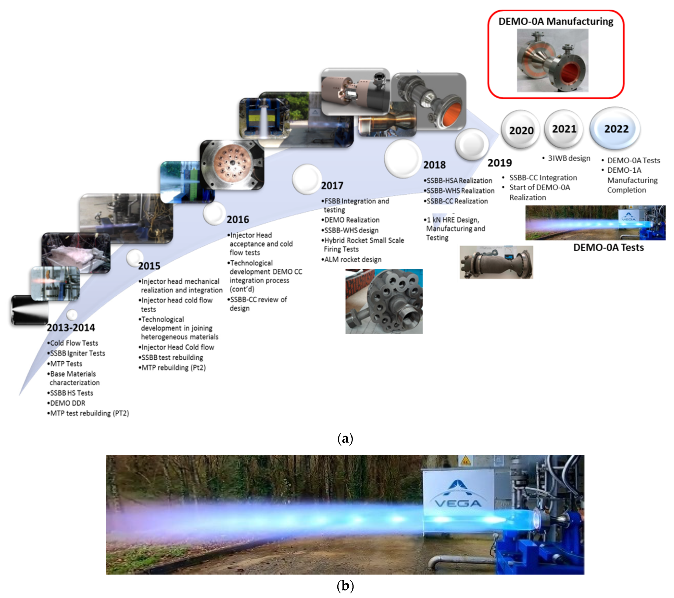
Figure 1. The DEMO development plan (a) and the DEMO-0A unit during the final firing test (b).
Aerospace 10 00607 g001
Figure 2. DEMO firing tests: chamber pressure results for three firing tests (FT).
Aerospace 10 00607 g002
Figure 3. DEMO assembly: (a) main components and schematics of the electroplating process applied to LRE cooling jacket manufacturing; (b) the DEMO-0A thrust chamber image.
Aerospace 10 00607 g003
Figure 4. The geometry description of the DEMO cooling jacket: a cross-section.
Aerospace 10 00607 g004
Figure 5. The chamber profile, hydraulic diameter of cooling channels, and design heat flux profile along the demonstrator.
Aerospace 10 00607 g005
Figure 6. Schematics of the cooling jacket: cross-section view, including information on materials and the adopted boundary conditions.
Aerospace 10 00607 g006
Figure 7. Input heat fluxes for all the considered points of the DEMO operative box (nominal and working points, delimiting the operative box of the engine).
Aerospace 10 00607 g007
Figure 8. Numerical model: (a) view of the single cooling channel; (b) details of the transversal and axial mesh distributions in the throat section (left) and the outlet section (right).
Aerospace 10 00607 g008
Figure 9. MTP BreadBoard: (a) test configuration with inlet/outlet flanges; (b) geometrical information; (c) detail on channel inlet.
Aerospace 10 00607 g009
Figure 10. MTP-BB results, comparisons of numerical and experimental results for a range of hot tests for: (a) pressure drops (test 24 and 26); (b) fluid temperature and solid wall temperature at a distance of 4 mm from the channel bottom surface (test 24) [51].
Aerospace 10 00607 g010
Figure 11. The axial profiles of the hot gas wall temperature (red), the channel bottom wall temperature (orange), and the fluid bulk temperature (blue).
Aerospace 10 00607 g011
Figure 12. The axial profiles of the static pressure.
Aerospace 10 00607 g012
Figure 13. The axial profiles of the local and average convective heat transfer coefficients (a), as well as the local and average Nusselt number (b).
Aerospace 10 00607 g013
Figure 14. The axial profiles of the Reynolds number and the Prandtl number.
Aerospace 10 00607 g014
Figure 15. The axial profiles of the thermo-physical properties: (a) density and viscosity; (b) specific heat and thermal conductivity.
Aerospace 10 00607 g015
Figure 16. The nominal operating point: dimensionless temperature distribution, including some transversal slices.
Aerospace 10 00607 g016
Figure 17. Dimensionless temperature field, transversal slices at outlet section, x/L = 0.13 (re-attachment point region), x/L = 0.52 (convergent), x/L = 0.61 (throat section and fluid bulk temperature equal to critical values), x/L = 0.75 (divergent), inlet section: (a) nominal point; (b) point A; (c) point C.
Aerospace 10 00607 g017
Figure 18. Thermo-structural analyses regarding DEMO-0A thrust chamber, equivalent Von Mises stress [Pa]: (a) complete model; (b) focus on throat region.
Aerospace 10 00607 g018
Table 1. The main nominal performance parameters of HYPROB DEMO.
O/F3.4PCC5.5 MPa
Reaction efficiency0.98Isp286 s
Thrust30 kNAcc/At4.0
Table 2. Boundary conditions at inlet in terms of fluid mass flow rate, temperature, and pressure for all the working points considered.
Working Pointsm
[kg/s]
Tin
[K]
Pin
[MPa]
O/F
[-]
N0.020011016.03.4
A0.018312015.74.08
B0.021810016.33.43
C0.021810016.32.83
D0.018312015.73.36
Table 3. Results of grid-independence analysis.
Type of Mesh∆P
[MPa]
Outlet Fluid Bulk Temperature
Tb,f out [K]
Liner Maximum Temperature
Tw, hg max [K]
Channel Bottom Wall Maximum Temperature
Tw, ch max [K]
1—coarse5.051420.1600.4555.4
2—fine5.094420.4610.8562.7
3—finest5.096420.5611.5563.4
Table 4. Summary of the CFD results concerning the MTP BreadBoard numerical rebuilding campaign (the elaboration from the results is given in [54]).
TestsTin
[K]
Tout
[K]
∆T Error%Pin
[MPa]
Pout
[Mpa]
∆P
Error%
Wall Channel
Maximum T Error%
2137.1245.20.6%11.17510.312−4.0%0.9%
4140.8261.2−1.3%12.90512.0611.6%1.5%
6142.1263.20.9%15.64914.872−4.2%1.3%
7139.6264.40.2%16.72215.943−2.5%0.6%
Table 5. Test matrix of the present numerical campaign.
RunInlet TemperatureInlet PressureMass Flow Rate Imposed Heat Flux
Tin,f
[K]
Tin,f* (Tin,f/Tin,f−nom)Pin [MPa]Pin* (Pin/Pin,nom)m [kg/s]m* (m/mnom)O/F
11101.0016.01.000.0201.003.4Nominal
21201.0915.70.980.01830.914.08Point A
31000.9116.31.000.02181.093.43Point B
41000.9116.31.000.02181.092.83Point C
51201.0915.70.980.01830.913.36Point D
Disclaimer/Publisher’s Note: The statements, opinions and data contained in all publications are solely those of the individual author(s) and contributor(s) and not of MDPI and/or the editor(s). MDPI and/or the editor(s) disclaim responsibility for any injury to people or property resulting from any ideas, methods, instructions or products referred to in the content.