Article

Numerical Study on Convective Heat Transfer of Liquid Metal Gallium in Turbine Guide Vane

1
School of Energy and Power Engineering, Beihang University, Beijing 100191, China
2
Research Institute of Aero-Engine, Beihang University, Beijing 100191, China
*
Author to whom correspondence should be addressed.
Aerospace 2023, 10(6), 548; https://doi.org/10.3390/aerospace10060548
Submission received: 26 April 2023 / Revised: 28 May 2023 / Accepted: 6 June 2023 / Published: 8 June 2023
(This article belongs to the Section Aeronautics)

Abstract

:
The traditional blade cooling method can no longer meet the requirements of high cooling efficiency in modern engines. In order to solve this cooling problem, this paper proposes cooling turbine guide blades based on liquid metal. The feasibility was preliminarily verified using a one-dimensional heat conduction model. Then, using a numerical method, we found that the cooling effect of liquid metal is much better than that of air cooling. The main reason for its good cooling effect is that the heat transfer coefficient of liquid metal reaches a magnitude of tens of thousands. Moreover, as the inlet temperature of the liquid metal decreases and the inlet Reynolds number increases, the liquid cooling effect becomes better. The definition of the heat transfer quality factor can reflect the reasons for the influence of the inlet temperature of the liquid metal.

1. Introduction

As the heart of an aircraft, the aero-engine is a very complex and sophisticated thermal machinery that provides the necessary power for aircraft flight and directly affects the performance of the aircraft. The ideal working cycle of the aero-engine is the Brayton cycle, in which the turbine inlet temperature significantly affects the engine performance. Increasing the turbine inlet temperature can significantly improve the engine output power [1]. Keeping a constant engine size, engine thrust can be increased by 8–13%, and engine cycle efficiency can be increased by 2–4% for every 56 °C increase in turbine inlet temperature [2], so the inlet temperature has been increasing in recent years. The existing gas temperature far exceeds the durable temperature of the vane material, and advanced cooling technologies have been developed to solve this problem. On the one hand, we can study new cooling technologies to improve the cooling efficiency of turbine vanes. On the other hand, seeking new cooling media is also a good way to improve cooling capacity.
At present, the cooling mode of vanes mainly involves the combination of external air film cooling and internal channel cooling [3]. In particular, the currently used methods for cooling the turbine guide vanes are film cooling and jet impingement at the leading and middle section of vanes, and pin-fins/dimple cooling at the trailing edges [4]. As for the blade internal cooling technology, the main research aim is to increase the internal heat transfer coefficient and heat transfer area. Han et al. [5,6] studied the effects of rib spacing, rib height ratio, and rib shape on heat transfer in cold channels with ribs. Elfer et al. [7] used PIV measurement technology to analyze the complex flow structure in the U-shaped channel with 45° inclined ribs. Zhang et al. [8] proposed an optimization method for rib structure size. In the first step, the rib height was fixed, and the rib spacing was changed to determine a relatively good result of rib spacing. In the second step, the ratio of rib spacing to rib height was fixed, and the rib height was changed to obtain a relatively good rib height value. The rib height to hydraulic diameter ratio e/Dh = 0.235, and the rib spacing to the rib height ratio p/e = 7.5, have relatively high heat transfer coefficients and low pressure loss. Tareq et al. [9] studied the influence of rib placement at the inlet, middle, and outlet of the U-shaped channel on the flow and heat transfer in the channel and found by comparison that the model pressure loss coefficient of the two ribs at the middle and outlet position was the largest, while the model heat transfer coefficient of the two ribs at the entrance and middle position was the largest. With respect to the air film cooling technology of the blades, Gao et al. [10] examined the cooling characteristics of the blade surface covered by a full air film with a dustpan hole with a compound angle. Compared with the results of the round hole with the same hole, due to the dustpan hole, the blowing ratio increased from 0.4 to 1.5, and the jet was well attached to the surface. The film cooling efficiency of the suction surface and pressure surface was improved. Leylek et al. [11,12,13] systematically studied the flow heat transfer characteristics of air film cooling in round holes and formed holes, and the study showed that the vortex structure of the air film cooling jet was the most important factor affecting the cooling effect, among which the kidney vortex was the main reason for the blowing away of the round air film hole at a high blowing air ratio. Forming the air film hole can reduce the cooling jet velocity at the outlet of the hole, weaken the kidney vortex, and slow down the mixing of cool air and gas, so the covering effect of the air film can be improved. Kim et al. [14] applied the forming hole to the leading edge of the blade for air film cooling and found that improving the shape of the forming hole could improve the effectiveness of air film cooling. Cho et al. [15] studied the formed gas film holes with different composite angles, and the research showed that the cooling effect of the formed holes with composite angles was significantly better than that of the rounded holes with composite angles. Additionally, the uniformly expanded air film holes at the exit section had a better cooling effect. Gritsch et al. [16] found in their experiments that the composite angle applied to the molding hole led to a poor cooling effect at a high blowing ratio and the negative effect could be overcome by designing the molding hole into an asymmetric form. Kim et al. [17] conducted a comparative study on the cooling effect of crescent-shaped, dumbbell-shaped, slit-shaped, and fan-shaped outlet air film holes and found that the best cooling effect under a low blowing air ratio was achieved with a crescent-shaped hole, while the best cooling effect under a high blowing air ratio was achieved with a dumbbell-shaped hole. Kusterer et al. [18] developed a kind of air film forming hole called NEKOMIMI, which can form a flow structure of anti-kidney vortex, inhibit the development of kidney vortex, weaken the mixing between gas and cold air and improve the air film cooling effect under high a blowing ratio. Lee et al. [19,20] applied the numerical simulation method and the approximate fitting method to optimize the geometry of the forming holes, and the optimized objective function of the air film cooling effect of the holes was improved by 28%.
After a comprehensive analysis of the current turbine vane cooling technologies, we found three problems: (1) The amount of cool air in the vane is continuously increasing, and the engine performance tends towards the limit. At present, the cooling gas flow rate of the turbine reaches more than 20%. The increase in the compressor pumping capacity makes this part of the gas not heated enough through the combustion chamber to work, which adversely affects the power and efficiency of the engine, and even offsets the benefits brought by the increase in the turbine front temperature. (2) The vane structure becomes more and more complex, and as the design and processing difficulty increase, the cost also increases. (3) Air film holes affect vane strength and thermal barrier coating spraying. In addition, the existing cooling efficiency cannot meet the turbine inlet temperature of future engines at 2400 K.
Apart from changing the blade structure, the new cooling medium liquid metal can also lead to an excellent cooling capacity. As a kind of low-melting-point liquid metal, gallium attracted our attention due to its low vapor pressure, nontoxicity, low viscosity, and metallic electrical conductivity performance [21]. Liquid metal gallium has emerged rapidly as an important heat-transfer medium because of its high thermal conductivity and ultra-high convective heat transfer coefficient, which is about five times higher than that of the conventional medium, water [22]. In addition, the boiling points of liquid metals exceed 2000 °C, which facilitates stable heat transfer at a high temperature [23]. In fact, the technique of using liquid metals as heat transfer fluids has a long history; it was first carried out in nuclear reactors in the 1940s and has been continuously developed until now, with tremendous achievement [24], including in high-performance computer chips [25,26], solar power plants [27,28,29,30], high-powered LEDs [31], spacecraft thermal energy storage [32], hydrocarbon-fueled scramjets [33] and many other fields [34]. Many experiments and simulations of this property have also been conducted on such fluids [35,36,37,38,39]. Deng et al. [31] proposed a high-power light-emitting diode (LED) active cooling scheme using liquid metal as a coolant and evaluated the heat dissipation performance of the liquid metal cooling system through experiments. The results showed that the liquid metal cooling system had a higher cooling capacity than the water-based cooling system. The high convective heat transfer coefficient was the main reason that the liquid metal was a good coolant. This liquid metal cooling system has the advantages of good cooling performance and saving energy. Sharma et al. [40] analyzed the flow heat transfer effect of liquid gallium metal and water in different microchannel structures through numerical simulation. Through the analysis of A-trapezoidal, V-trapezoidal, and rectangular microchannel structures, it was shown that under the same flow rate, if only the cooling effect was considered, without considering pump power consumption, the A-trapezoidal microchannel structure with gallium as the working medium had the best cooling effect. Mansour et al. [41] conducted numerical and experimental studies using a rectangular small-channel cooler with liquid metal as the coolant, proving that using gallium alloy as a cooling fluid can increase the dissipation of high-heat flow in powered electronic devices. Zhang et al. [42] conducted an in-depth study on laminar heat transfer in microtubes with water and liquid metal as heat transfer fluids, and the results showed that liquid metal had a better heat transfer performance in microtubes, and the shorter the pipe, the better the cooling performance of liquid metal; in contrast, in microtubules, when the flow rate was low, the water cooling effect was poor. Wu et al. [43] used numerical methods to study the flow and heat transfer properties of liquid-metal-based radiators and discussed different types of working media, different cross-section shapes of microchannels, and different inlet velocities. It was found that lithium and circle are the most suitable working medium and microchannel section shape, respectively. In addition, the inlet velocity has a great effect on the flow and heat transfer performance. Although the application of liquid metal still has some problems, such as high price and strong corrosion to some metal materials [44,45], liquid metal cooling is still a good solution when faced with the problem of high heat fluids, which conventional heat exchange fluids cannot solve.
Currently, studies on liquid metal cooling are widely conducted, but research on turbine guide vanes using liquid metal as the working fluid is scarce. Turbine vane cooling technology with air as the cooling medium has gradually reached its limit in cooling efficiency and cannot meet the requirements for further increasing the turbine inlet temperature. Therefore, it is urgent to develop new turbine vane cooling technology. Compared with the traditional cooling medium, liquid metal gallium and its alloy have great advantages in cooling effect and potential application value, such as high thermal conductivity, high safety, wide single-phase temperature range, and the ability to flow as a liquid in the whole operation range of aircraft, which makes it possible to apply liquid metal cooling for the thermal protection of aero-engine high-pressure turbine guide vanes. Our research group proposed for the first time a technical scheme for cooling turbine guide vanes with liquid metal as the cooling medium so as to realize the cooling of vanes without using cold air. The circulating cooling system consists of an electromagnetic pump, a heat exchanger, and cooling channels distributed in the turbine vane. Considering the expansion of liquid metal by heat, an expansion joint is set in the cooling system to prevent the pipeline from deformation and even rupture under the influence of liquid expansion. The cooling system uses the extremely high heat transfer coefficient of liquid metal to absorb heat inside the vane passage. The heated liquid metal flows to the heat exchanger in the outer culvert channel of the engine through the pipeline arranged inside the casing. The liquid metal heat exchanger adopts the brand-new working medium and heat exchange technology, which is conducive to the overall performance of the engine, and can also greatly reduce the volume required by the heat exchanger so as to meet the demand of ultra-compactness. Then, using the low-temperature air in the engine culvert channel to cool the high-temperature liquid metal, the cooled liquid metal flows into an electromagnetic pump arranged inside the casing for pressure so as to realize the flow in a circle and the heat transfer of the cooled liquid metal. The main reasons for the selection of an electromagnetic pump are that the pump has no moving parts, high reliability, no vibration, and low noise. Additionally, the high conductivity of liquid metal provides the potential for efficient and compact pumping and has the characteristics of complete sealing, simple structure, and low power consumption [46]. The proportion of cool air used for guide vanes is reduced to 0%, and the saved cool air is used for the work, so the engine thrust can be increased. The increased weight of the liquid metal cooling circulation system has little impact on the overall engine performance, and the overall benefit is very considerable.
In this paper, a liquid metal cooling circulation system is proposed, and the principle feasibility of the new cooling technology is preliminarily demonstrated through a one-dimensional steady-state heat conduction calculation and three-dimensional steady-state numerical simulation technology. The three-dimensional steady-state numerical simulation of the convective heat transfer of liquid metal is analyzed in detail.

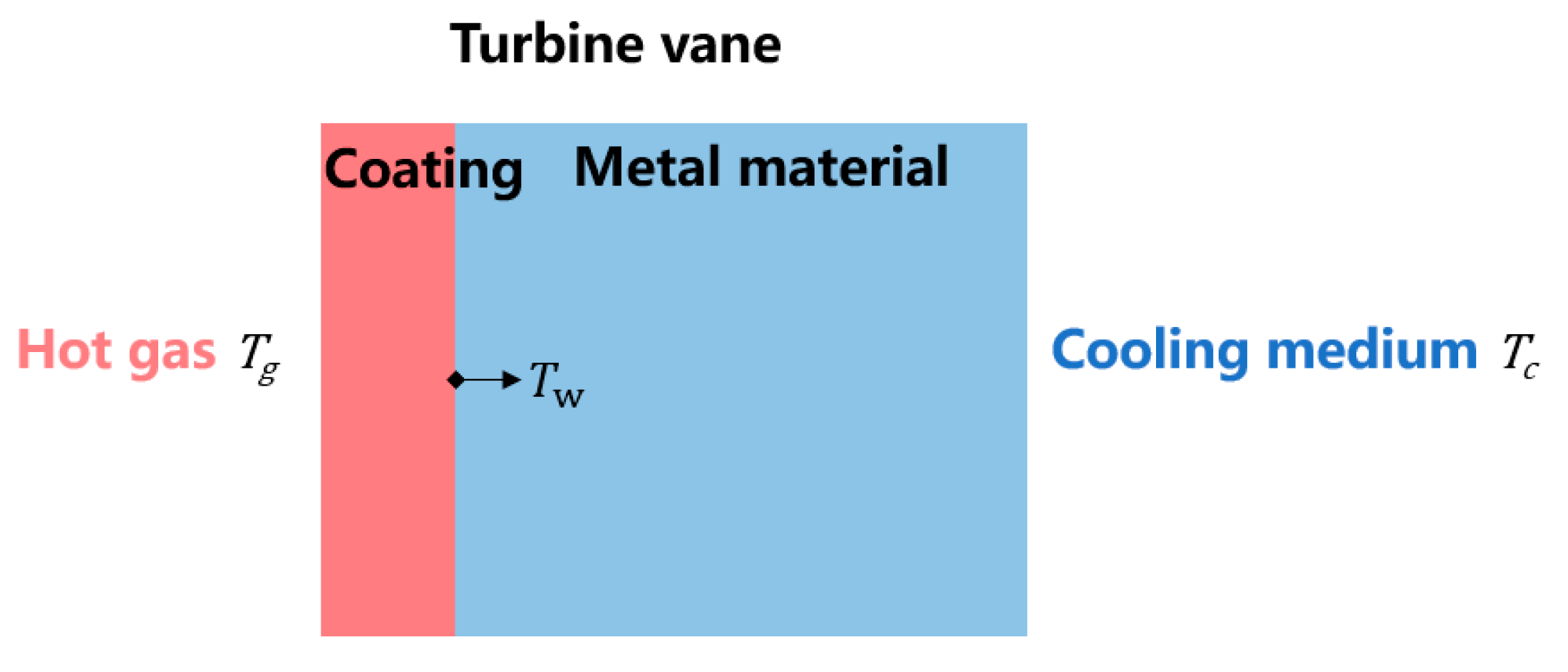
2. One-Dimensional Thermal Conductivity Calculation

To verify the feasibility of the cooling system, we conducted a one-dimensional thermal conductivity calculation, and the complex heat transfer of turbine vanes was simplified to one-dimensional thermal conductivity along the flow direction of the turbine channel. As shown in Figure 1, the infinite plate structure composed of thermal barrier coating and vane in series is located in the representative gas and cool air channel. T g represents the temperature of the high-temperature gas channel at the far end, located on the left side of the infinite plate, and T c is the temperature of the cooling medium channel at the far right side. The interface between the coating and the vane of the metal material is defined as the surface temperature of the metal material, T w . The temperature of the metal material T w was compared under two cooling modes: air and liquid gallium metal.
The one-dimensional computational boundary conditions and physical property parameters are shown in Table 1. h , λ , and δ represent the heat transfer coefficient, heat conductivity coefficient, and thickness, respectively. When studying the cooling media is air and liquid gallium, the highest temperature of the vane is taken as the solid temperature at the interface between the coating and the metal material.
When the cooling medium is liquid gallium metal, we assume that the flow velocity of the cold channel in the vane is 5 m/s and the diameter of the cold channel in the vane is 6.3 mm. The relationship between the classical Nusselt number in the tube, the flow Reynolds number, Re, and the Prandtl number of the working medium, Pr, was adopted [47].
Nu = 7 + 0 . 025 Re 0.8 Pr 0.8
It can be calculated that the convective heat transfer coefficient h in the channel at 310 K is 98,400 W / m 2 K . This is about 49 times the convective heat transfer coefficient of air (as shown in Table 2).
According to the convective heat transfer coefficient, the maximum temperature of the metal material can be calculated as 1769 K and 1174 K, respectively, when air and liquid gallium are used as the cooling media. As the metal temperature resistance limit is 1350 K, the following conclusions can be drawn: when the turbine front temperature is 2400 K, the turbine vane cooling system using air as the cooling medium cannot meet the requirements of vane thermal protection only by simple convection heat transfer. The new turbine vane cooling system, which uses liquid metal gallium as the cooling medium, can successfully reduce the turbine vane temperature to below 1350 K to achieve good thermal protection for the turbine guide vanes. Therefore, based on the theory of one-dimensional steady-state heat conduction, the feasibility of using liquid metal gallium as a cooling medium for aero-engine high-pressure turbine vanes is preliminarily demonstrated.

3. Three-Dimensional Steady-State Numerical Computation

In the three-dimensional steady-state calculation, the classical vane was selected as the flow model. Firstly, the simulation results were compared with the existing experiments to verify the effectiveness of the established model. Then, the cooling effects of air and liquid metal under the same conditions were compared. The temperature distribution on the turbine vane surface and inside was obtained. Finally, flow and heat transfer performances with different inlet Reynolds numbers and inlet temperatures were obtained and analyzed.

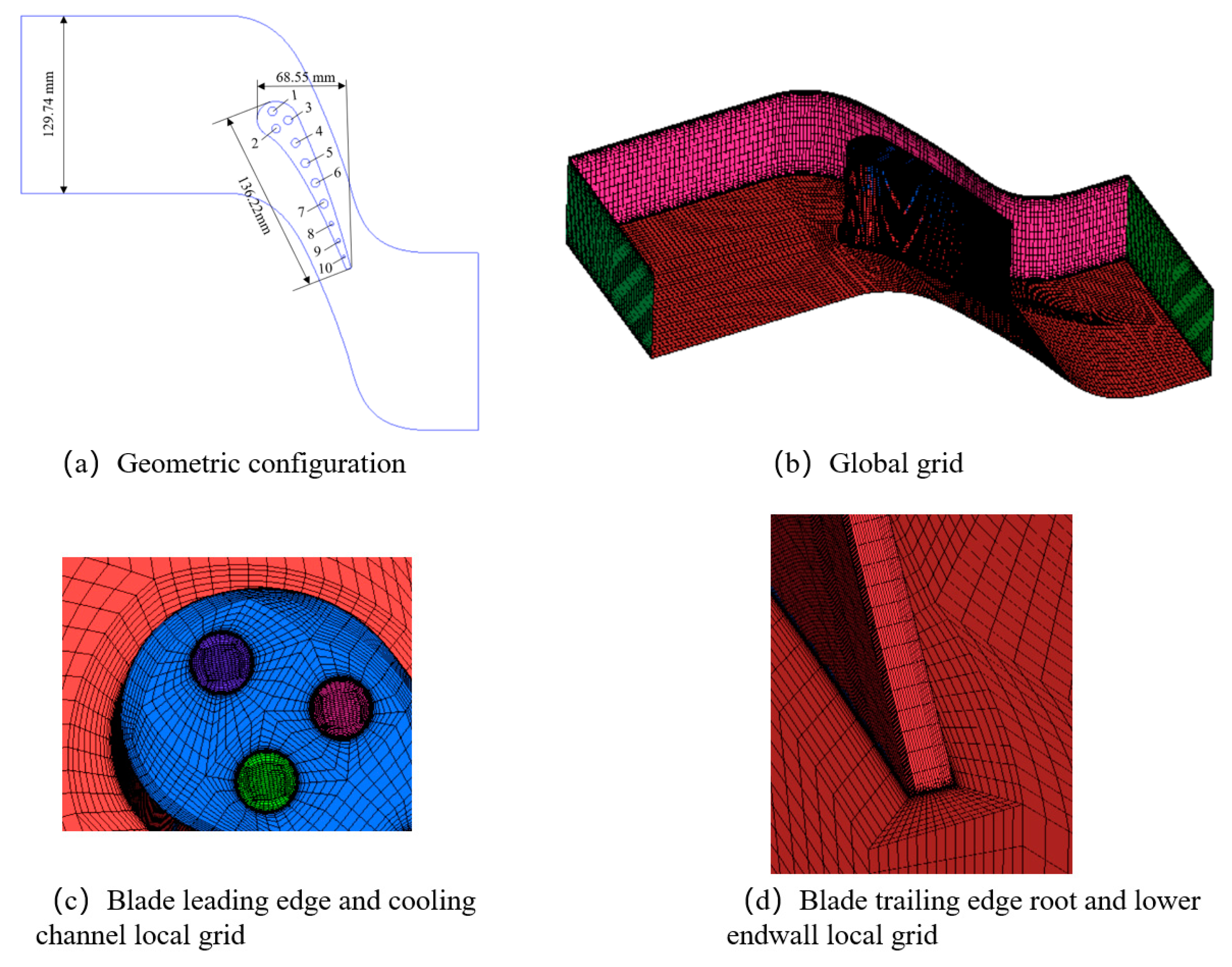
3.1. Geometric Configuration

The investigated configuration is the MARK II vane, a high-pressure turbine nozzle guide vane convectively cooled by ten cooling channels. Extensive experimental investigations of the uncoated vane can be found in Hylton et al. [48]. Figure 2 shows the geometric configuration and computational grid. The periodic boundary form of a single vane channel was used in the calculation model. In the numerical simulation, a three-dimensional partitioned hexahedral mesh was used in the fluid part. The mesh was encrypted in the fluid boundary layer at the fluid–structure coupling interface to ensure the first layer of mesh y+ < 1, and we set the expansion ratio to 1.1. In the CHT (coupled heat transfer) analysis, conservation of heat flux and temperature are used in the fluid–solid interfaces in order to consider the effect of the real temperature of the vane surface on the thermal boundary layer. Steady-state governing equations were solved for fluid and solid zones using ANSYS CFX. Reynolds Average Navier–Stokes equations were solved in all fluid zones along with the shear stress transport (SST) turbulence model of Menter et al. [49].

3.2. Governing Equations

The 3D steady compressible Navier–Stokes was solved using a cell-centered finite volume method on the mesh. The governing equations for continuity, momentum, and energy could be written as follows.
Continuity equation:
u x + v y + w z = 0
where u, v and w, in m/s, are, respectively, the velocity in the x, y and z direction.
Momentum equations:
u u x + v u y + w u z = 1 ρ p x + η ρ 2 u x 2 + 2 u y 2 + 2 u z 2
u v x + v v y + w v z = 1 ρ p y + η ρ 2 v x 2 + 2 v y 2 + 2 v z 2
u w x + v w y + w w z = 1 ρ p z + η ρ 2 w x 2 + 2 w y 2 + 2 w z 2
where p, in Pa, is pressure, ρ, in kg/m3, is density, and η, in Pa·s, is viscosity.
Energy equations in the fluid region:
u T x + v T y + w T z = λ f ρ C p 2 T x 2 + 2 T y 2 + 2 T z 2
in the solid region:
2 T x 2 + 2 T y 2 + 2 T z 2 = 0
where T, in K, represents temperature, λf, in W/(m·K), is thermal conductivity, and Cp, in J/(kg·K), is the specific heat capacity.

3.3. Physical Parameters and Boundary Settings

3.3.1. Dominant Physical Property

The fluid in the mainstream zone was set as an ideal gas, and molecular viscous and heat conduction coefficients, respectively, μ and K , are expressed as a function of temperature using Salander’s formula:
μ T = μ 0 T T 0 3 / 2 T 0 + S T + S
K T = λ 0 T T 0 3 / 2 T 0 + S T + S
where μ 0 = 1.7894 × 10 5   Pa s , T 0 = 273.11   K , λ 0 = 0.0261   W / ( m K ) and S = 110.56 .
The specific heat capacity of gas C P is fitted by the temperature polynomial:
C P = a 0 + a 1 T + a 2 T 2 + a 3 T 3 + a 4 T 4
where: a 0 = 957.110256 , a 1 = 0.2365234 , a 2 = 5.141114 × 10 6 , a 3 = 3.3917446 × 10 9 , a 4 = 6.092964 × 10 12 .

3.3.2. Solid Physical Property

The vane material used was ASTM type 310 stainless steel. This material is usually not used for turbine vanes, but it was chosen for the experiments due to its low thermal conductivity. Its density ρ = 8030   kg / m 3 and its specific heat C p = 502   J / kg · K . The temperature dependency of the thermal conductivity was taken into account in the calculations. Thermal conductivity is a linear function of temperature:
K = 0.0115 T + 9.9105

3.3.3. Boundary Setting

The inlet and outlet boundary conditions of the turbine passage are shown in Table 3.
For the internal cooling passage of the vanes, in order to reduce the difficulty of early calculation, separate inlet temperature, inlet velocity, and outlet pressure were set for each of the ten internal cooling passages as boundary conditions, as shown in Table 4.

4. Calculation Result and Analysis

4.1. Grid-Independent Verification

In order to save computing resources and ensure that the calculation results were independent of the number of divided grids, a grid-independent solution analysis was carried out. For the process of solving the grid-independent solutions, the solving model and boundary conditions are shown in Table 5. We calculated the average temperature of the mainstream outlet when the grid is 900,000, 1,000,000, 1,180,000, 2,000,000, and 4,000,000, respectively. The calculation results are shown in the table below:
It can be seen from the table that the calculation results of the grid number of 1,180,000 and 4,000,000 are very similar. After comprehensive consideration of the grid number and flow condition, we concluded that the grid number of 1.18 million meets the requirement of the independent solution, so it was used as the calculation grid.

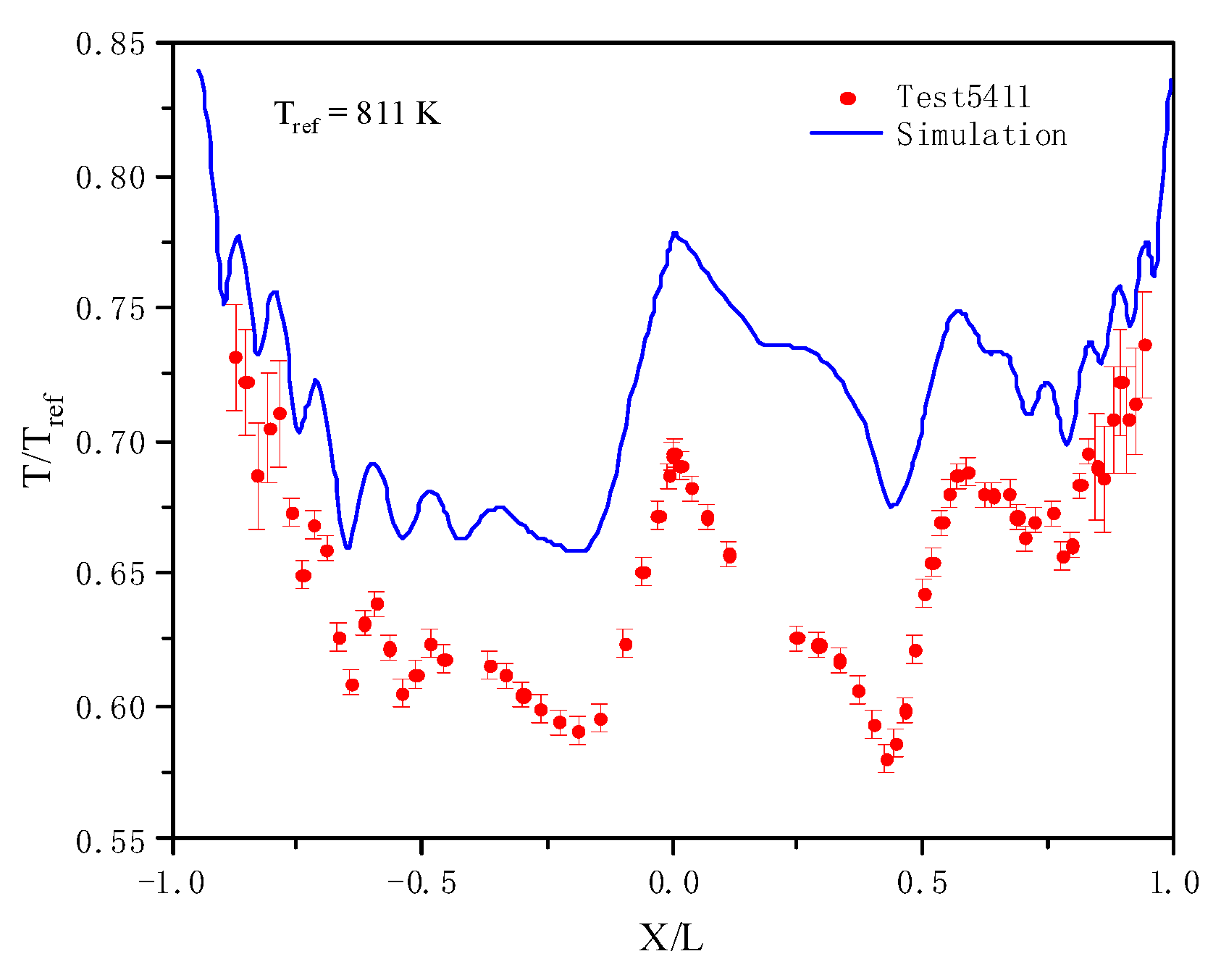
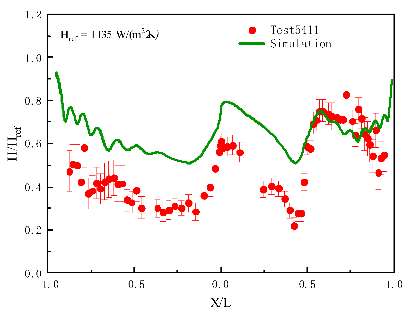
4.2. Experimental Verification

The axial chord length L of the vane was selected as a benchmark, and the dimensionless quantity X/L on the X axis was used to display different positions on the vane surface. The difference between the suction surface and the pressure surface on the vane surface was determined by the positive and negative X/L values; that is, the X-axis vertex of the leading edge of the vane was usually taken as the origin, X/L = 0, the X-axis vertex of the trailing edge was 1, and the pressure surface X/L was negative. The suction surface X/L was positive. The temperature distribution and heat transfer coefficient distribution on the outer wall of the vane middle diameter were plotted on the same axis with the experimental data of Hylton et al. [48], and the results are shown in Figure 3.
The simulation results of wall temperature are slightly higher than the experimental results, and the maximum difference is about 17%, but the trend is consistent with the experimental data, and the results are consistent with the existing literature [50]. The difference is mainly due to two factors: on the one hand, the turbulence model used could not fully simulate the flow state under real conditions; these models usually ignore the influences of transition by regarding the whole boundary layer field as a full-turbulence flow, and they adopt empirical damping functions to simulate the viscous effects in boundary layers, which may not tell the transition flows apart accurately. On the other hand, the temperature-measuring thermocouple was buried 0.5 mm deep inside the vane during the experiment, and the data measured were not the temperature of the outer vane wall but rather the local internal temperature of the outer vane wall. In addition, in the numerical simulation, it was assumed that the upper and lower faces of Mark II vanes are adiabatic, but it is impossible to achieve a completely adiabatic in the experiment, and there is a certain loss of heat dissipation. Based on the above analysis, the simulation results are relatively accurate and reliable and can be used to predict results in a certain range.
The wall temperature is affected not only by the local mainstream turbulence intensity but also by the local mainstream velocity and boundary layer conditions. With the accelerated flow of the main flow in the passage, the boundary layer becomes thinner; the thermal resistance decreases, and the heat transfer coefficient increases. The numerical results show that on both sides of the vane, the temperature increases with the approach to the trailing edge of the vane, and with the decrease in vane thickness, the temperature curve gradually presents a “wavy shape” when the internal cooling channel approaches the outer surface of the vane. When X/L = 0.4 on the suction surface side, the temperature increases, and the static temperature of the main gas also increases through a shock wave. When the numerical simulation results are presented as point groups, the phenomenon of temperature discontinuity occurs because the vane heat is conducted in three dimensions, thus reducing the magnitude of temperature.
As for the heat transfer coefficient, the results are shown in Figure 4. We can see that the simulation results and the experimental results are in good agreement in terms of trend and order of magnitude. However, the heat transfer coefficient value of the numerical simulation results is generally larger than that of the experimental results, which is also consistent with the results of the temperature distribution diagram of the external wall in the figure. The wall temperature in the numerical simulation result is too large, resulting in a decrease in temperature difference. In the case of a certain heat flux, the heat transfer coefficient is indeed larger than the experimental value. Further observation shows that the difference between the numerical simulation result and the experimental result reaches the maximum near the strong suction-surface shock wave; that is, the temperature deviation between the numerical simulation results and the experimental results is the highest here. According to the analysis, the flow in the boundary layer in this region should be turbulent, and the Mach Number Effect is generated here, which generates the shock wave–turbulence interaction. The biggest impact of this interaction is that it amplifies the turbulent kinetic energy [51,52], thus amplifying the pulsation ability of the turbulence. That amplifies the heat transfer capacity of the turbulence, which accounts for the difference in results.

4.3. Air Cooling

Figure 5 shows the contour of the temperature distribution on the suction surface and pressure surface of the entire outer wall of the vane. We can see that the highest temperature of the vane is located at the trailing edge of the vane, and the temperature near the trailing edge changes significantly, mainly because the cooling channel near the trailing edge is narrow and very close to the outer wall of the vane, leading to a large temperature gradient and, correspondingly, large thermal stress.
Figure 6 shows the contour of the temperature distribution along the 10%, 50%, and 90% vane height sections. It can be seen that the temperature increases almost linearly with the distance from the cooling gas inlet surface, especially at the trailing edge position. The main reason for this is that the heat energy of the mainstream is transferred to the cooling working medium, and the constant pressure of the cooling gas is lower than the heat capacity, resulting in the temperature of the cooling working medium in the downstream increasing, and the cooling effect decreasing.

4.4. Liquid Metal Cooling

4.4.1. Comparative Analysis of Heat Transfer Effect

When gallium was used as the cooling medium, only the inlet boundary conditions of the cooling channel changed, and the inlet speed was uniformly set to 5 m/s. Other calculation models and simulation conditions show the same effect as air cooling. The results are shown in Figure 7.
Different from air cooling, when liquid metal Ga is used as the cooling medium, the temperature of different vane height sections changes little. The fundamental reason for this is that liquid metal has a high volume-specific heat capacity, resulting in its own temperature being low after carrying heat, meaning it has a strong cooling ability at different vane height sections, which further reduces the longitudinal temperature gradient of the vane. This is beneficial for the enhanced heat transfer of turbine vanes. However, the specific heat capacity of air is low, and its temperature rises rapidly with the increase in vane height. With the change in the flow process, the air temperature keeps rising, resulting in a substantial decline in its cooling effect. As a result, the temperature of the vanes at a 90% vane height is relatively high, the longitudinal temperature gradient of the vanes is high, and the thermal stress is also large.
Figure 8 and Figure 9 directly reflect the temperature gradient in each part of the vane middle-diameter section and the temperature distribution on the outer wall of the middle-diameter vane. Compared with conventional air cooling, liquid metal Ga has clear cooling advantages. The temperature gradient in the vane section is small, and the maximum temperature difference in the outer wall is more than 100 K. The temperature distribution in the vane changes little; that is, the temperature gradient of the vane is small, which is also conducive to reducing thermal stress.
In order to characterize the heat transfer effect of cooling media, the average heat transfer coefficient of the cooling channel wall was defined as H:
H = h l o c a l d A A = q T w T r e f d A A
where Tw is the wall temperature of the cooling channel and Tref is the qualitative temperature. Here, the inlet temperature of the cooling medium is the qualitative temperature, q is the wall heat flux of the cooling channel, and A is the area of the cooling channel.
As can be seen from Figure 10, the heat transfer coefficient of each cooling channel is different, but the difference is small. However, the heat transfer coefficient of liquid metal Ga is much larger than that of air, and the heat transfer coefficient of liquid metal Ga is about 100,000 magnitude, while that of air is only 1000 magnitude. Liquid metal has a high heat transfer coefficient due to its high thermal conductivity. This is the fundamental reason why liquid metal cools better than air.
In order to further analyze the variation law of thermal resistance in each part of the flow passage when liquid metal Ga is used as a cooling medium, the author arbitrarily drew a line through cooling channel 7 at the middle section of the vane and made the line pass through the vane and cooling channel from the pressure surface side to the suction surface side. The X-coordinate diagram of the dimensionless temperature and the line drawn along the vane is shown in Figure 11. The line is almost perpendicular to the outer wall of the vane.
As can be seen from the figure above, whether the cooling medium is air or gallium, the convective thermal resistance on the pressure surface is always greater than that on the suction surface, mainly because the heat transfer coefficient on the suction surface is large, resulting in a small difference between the temperature of the suction surface and that of the gas. Compared with the convective thermal resistance, the thermal resistance of conduction is much smaller. The convective thermal resistance of air as the cooling medium is much greater than that of liquid metal gallium as the cooling medium, which again verifies that the use of liquid metal can effectively strengthen vane heat transfer and reduce the thermal resistance of the cooling channel.

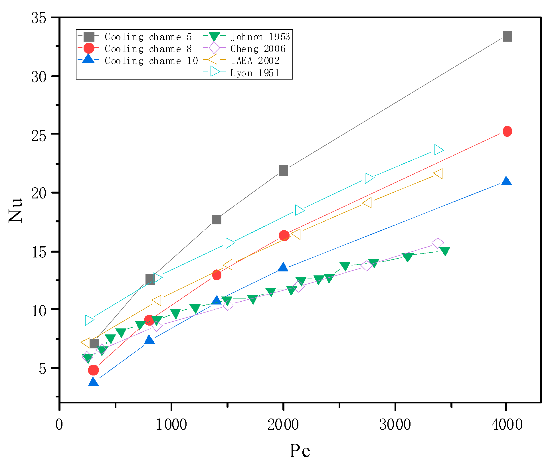
4.4.2. Influence of Cooling Channel Inlet Reynolds

The inlet Reynolds number of the cooling channel used in the numerical simulation is shown in Table 6. In each example, 10 cooling channels were made to have the same inlet Reynolds number. For example, when Re = 15,000, the inlet Reynolds number of cooling channels 1~10 was 15,000. Since the parameters of the geometric model were fixed, the definition formulae of Reynolds number were combined:
Re = ρ ν d μ
where: Re is inlet Reynolds number; d is pipe diameter of cooling channel, mm; ρ is density of liquid metal Ga, kg/m3; v is speed, m/s; μ is dynamic viscosity coefficient of liquid metal Ga, kg/(m·s).
In order to characterize the heat transfer effect of the cooling medium, the Nusselt number of the cooling channel wall was defined:
Nu = h d λ
where: h is the average heat transfer coefficient; d is pipe diameter of cooling channel, mm; λ is Ga heat conductivity coefficient, W/(m·K).
Figure 12 shows the distribution of the average Nusselt number on the cooling channel wall under different inlet Reynolds numbers. For the same fluid working medium, the Nusselt number of its wall can represent the strength of its convective heat transfer capacity in a certain geometric channel. It can be seen from Figure 13 that under different research conditions, the average Nusselt number on the cooling channel wall decreases with the decrease in the cooling channel pipe diameter, and the average Nusselt number on the cooling channel wall also increases with the increase in the Reynolds number at the cooling channel entrance; that is, the greater the Reynolds number at the cooling channel entrance, the better the heat transfer effect between liquid metal Ga and turbine blades, and the stronger the cooling power. This is because the higher the flow rate, the greater the Reynolds number, the higher the degree of turbulence, and the better the heat transfer effect, and the increase in flow rate changes the contact time between the liquid metal Ga and the hot end component. The contact time of Mark II vanes is shorter, while the liquid metal Ga is continuously supplied, so the temperature of liquid metal Ga at the end of the cooling channel is still low, with a better heat transfer ability.
The Peclet number was defined in order to compare it with the results in the available literature:
Pe = RePr
where: Re is inlet Reynolds number; Pr is inlet Prandtl number.
Figure 13 compares the relationship between the Pe number and the Nu number. We found that, on the whole, the heat transfer quality of the cooling channel is directly determined by the Peclet number. The larger the Peclet number, the larger the convective transport proportion, and the better the heat transfer effect of the cooling channel. At the same time, it can be seen that there is a wide discrepancy in predictions among the models. This discrepancy may be due to different experimental conditions, coolant properties, and coolant–wall resistance. Although the simulated working conditions, flow medium, and geometric parameters are different from those in the literature [53,54,55,56], the overall trend is consistent, and the order of magnitude is close, which further verifies the accuracy of the simulation.

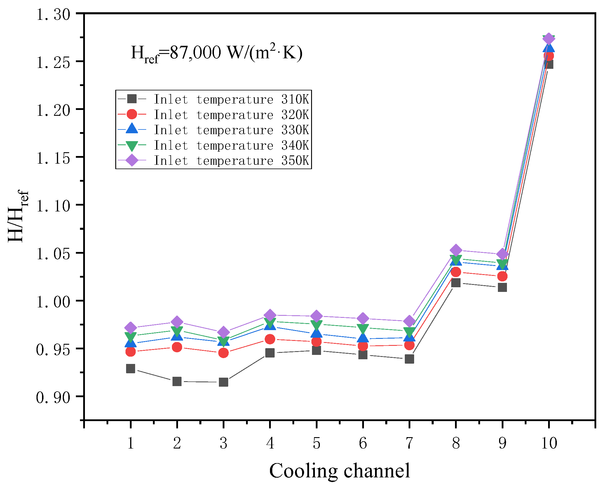
4.4.3. Influence of Cooling Channel Inlet Temperature

With the value fixed at 310 K, the inlet Reynolds number of liquid metal Ga was maintained between 40,000 and 70,000 at the boundary conditions of the inlet of the cooling channel and the velocity inlet. Specific parameters are shown in Table 7. The inlet temperature values under different calculation conditions are shown in Table 8.
Figure 14 shows the average heat transfer coefficient distribution curve of the cooling channel wall under different Ga inlet temperatures, where the qualitative temperature is the inlet temperature of Ga. Figure 14 shows that, with an increase in Ga inlet temperature, the average heat transfer coefficient of the cooling channel wall presents a weak rise. This is because in this temperature range, with the increase in Ga temperature, its enhanced heat transfer quality increases; that is, the thermal conductivity, specific heat capacity, and density, which are strongly correlated with the heat transfer capacity, increase with the increase in temperature.
In order to better explore the influence of temperature on the heat transfer coefficient, the enhanced heat transfer quality factor M lm for liquid-metal-enhanced turbine blade heat transfer is proposed, and its definition is as follows:
M lm = ρ λ C P μ 0.25
where: ρ is density of the medium, kg/m3; μ is dynamic viscosity of the medium, Pa·s; λ is thermal conductivity of the medium, W/(m∙K); Cp is specific heat capacity of the medium, J/(kg·K).The ideal high-temperature thermal drive medium should have high density, high volume expansion coefficient, high thermal conductivity, high constant pressure heat capacity, and low dynamic viscosity. These factors all meet the requirements for increasing the heat transfer quality factor M lm proposed in this paper, which indicates that the larger the heat transfer quality factor M lm , the better the heat transfer effect of liquid-metal-enhanced turbine blades. The results are shown in Table 9.

5. Conclusions

Numerical investigations of convective heat transfer performances in liquid-metal-based on turbine guide vanes are presented in this paper. During the simulation processes, different working medium types, inlet Reynolds values, and inlet temperatures were considered so that their influences on the vanes’ characteristics could be analyzed. From the calculation results, some important conclusions were obtained, as follows:
(1)
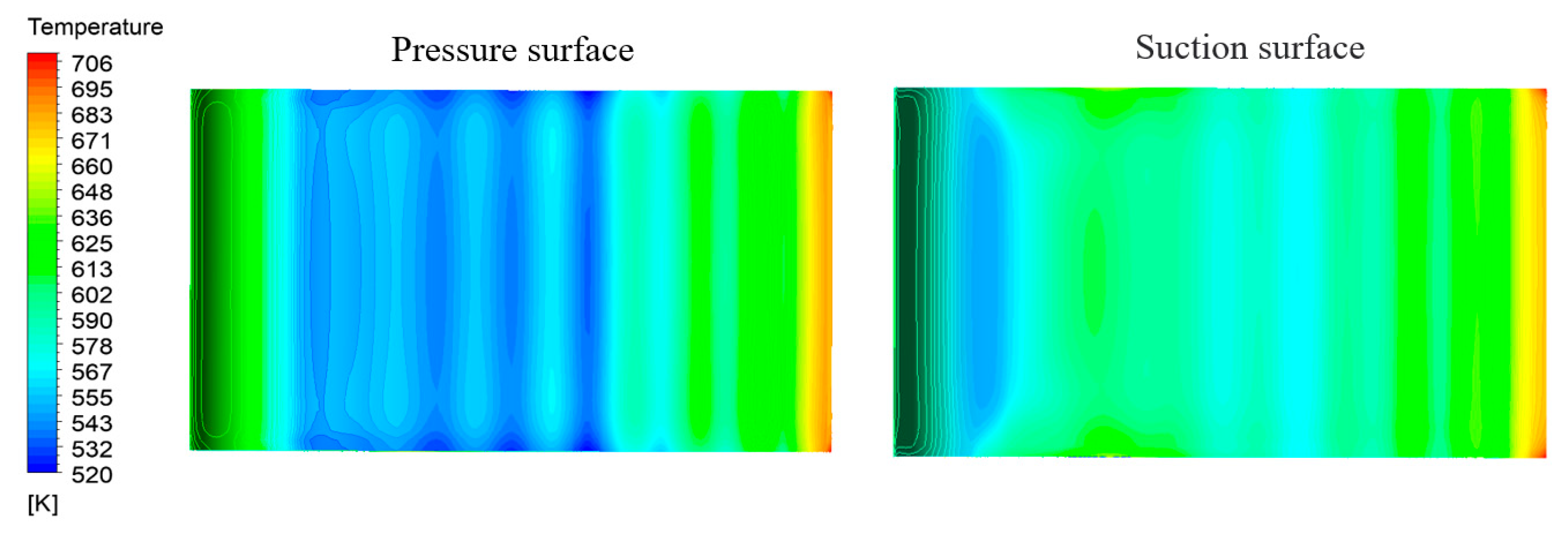
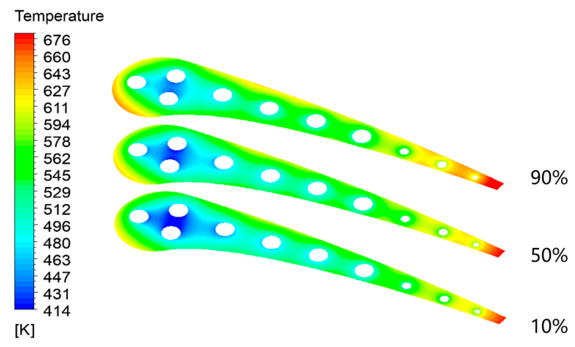
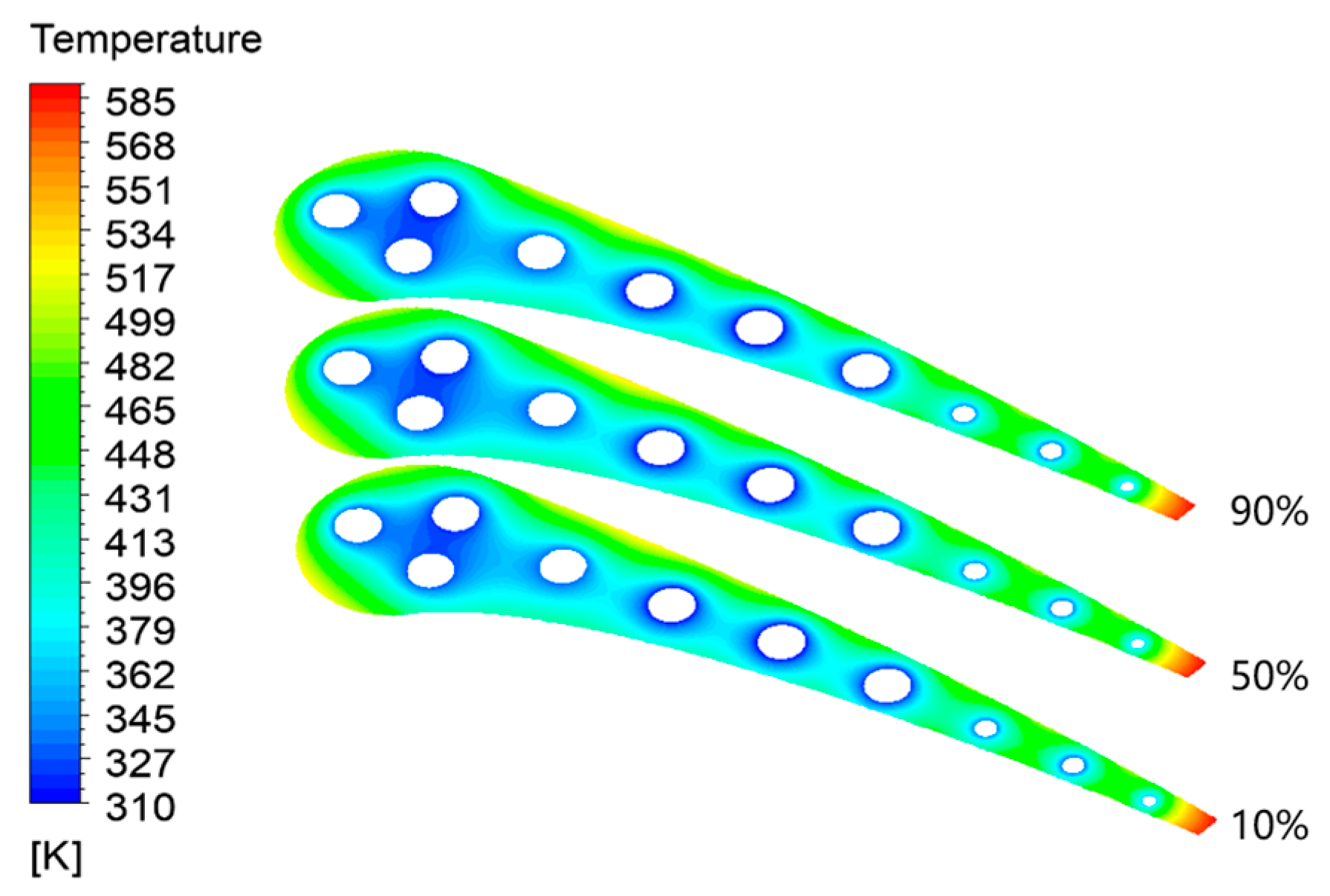
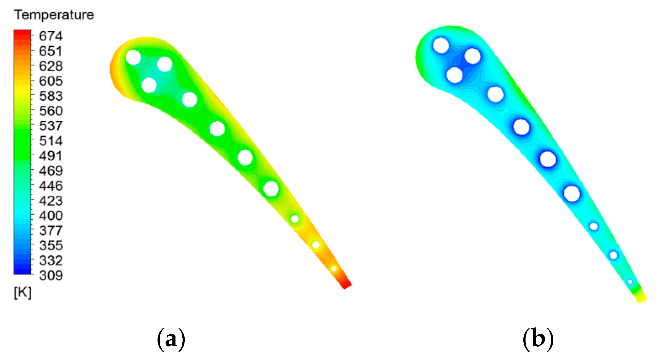
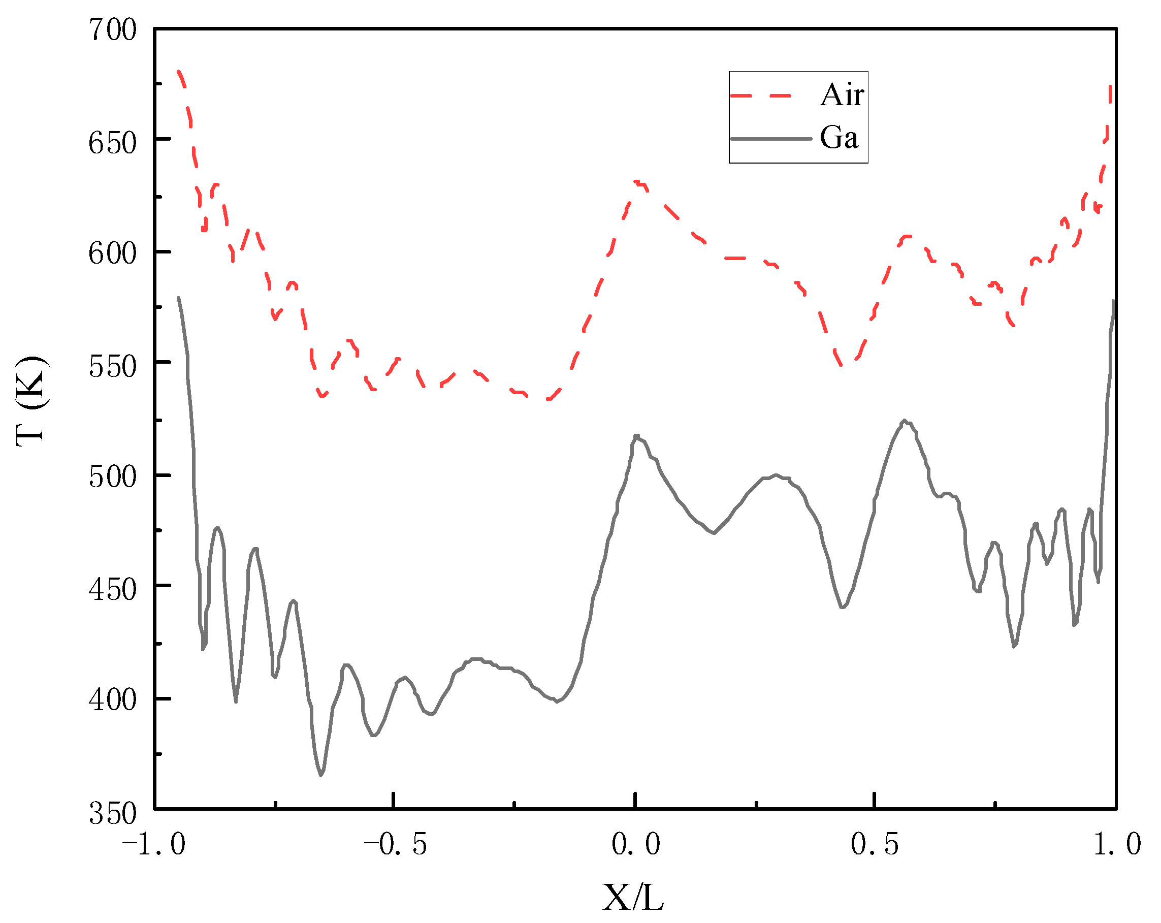
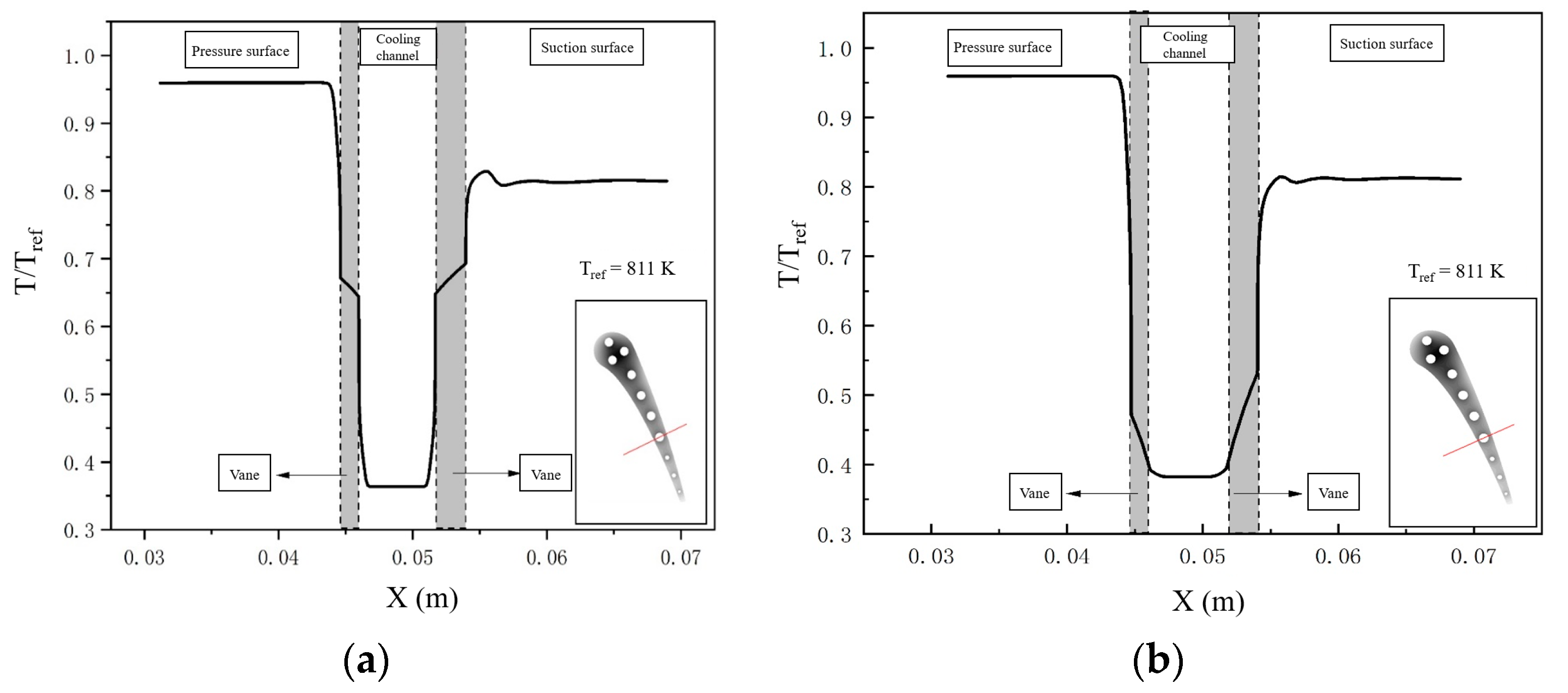
Compared with conventional air cooling, liquid metal Ga has obvious clear advantages, such as a lower temperature gradient and lower thermal stress, no matter the temperature gradient of each part of the middle-diameter vane section or the temperature distribution on the outer wall of the vane.
(2)
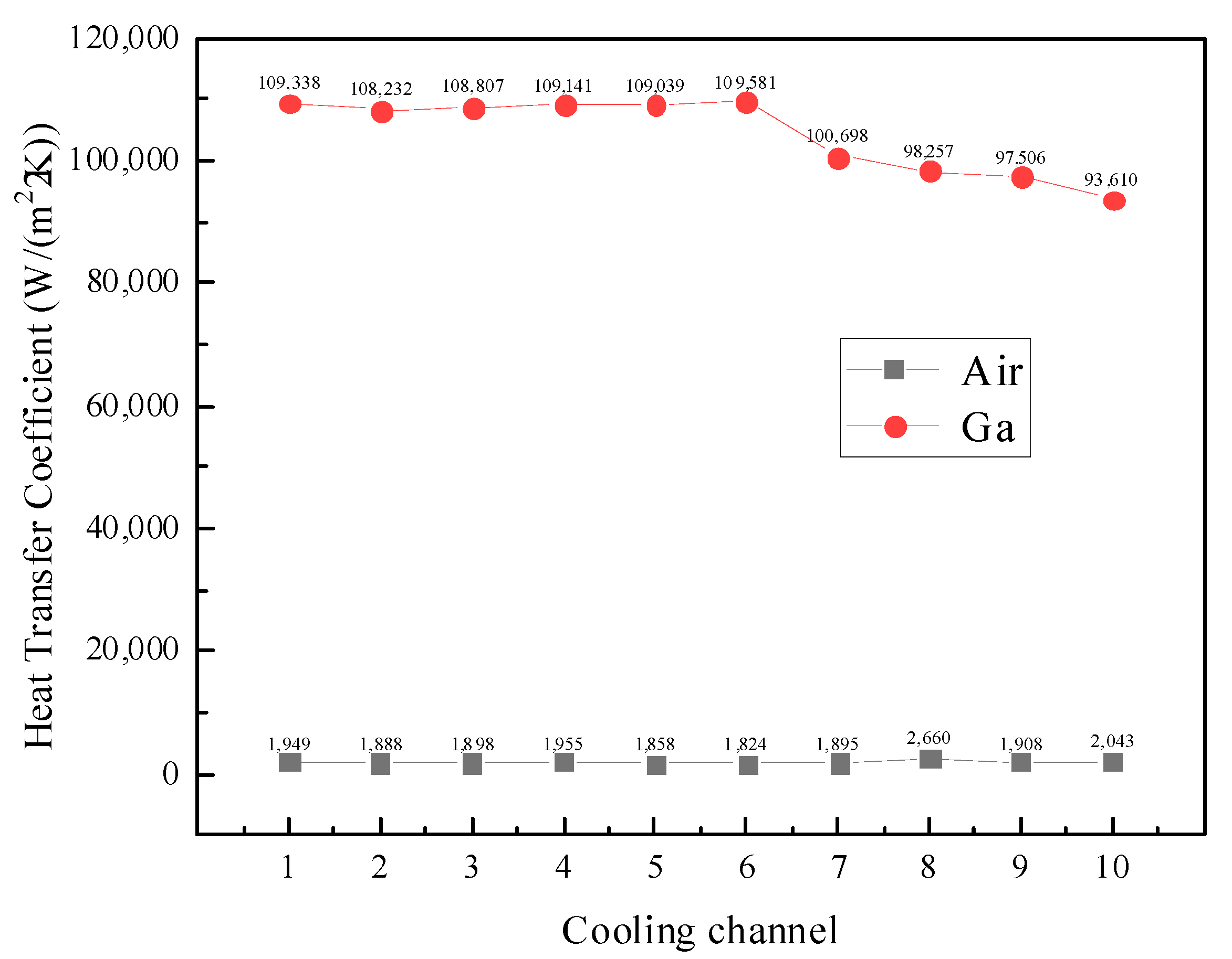
The heat transfer coefficient of liquid metal is much higher than that of air by tens of thousands of magnitude, which is the fundamental reason why liquid metal cooling is better than air cooling.
(3)
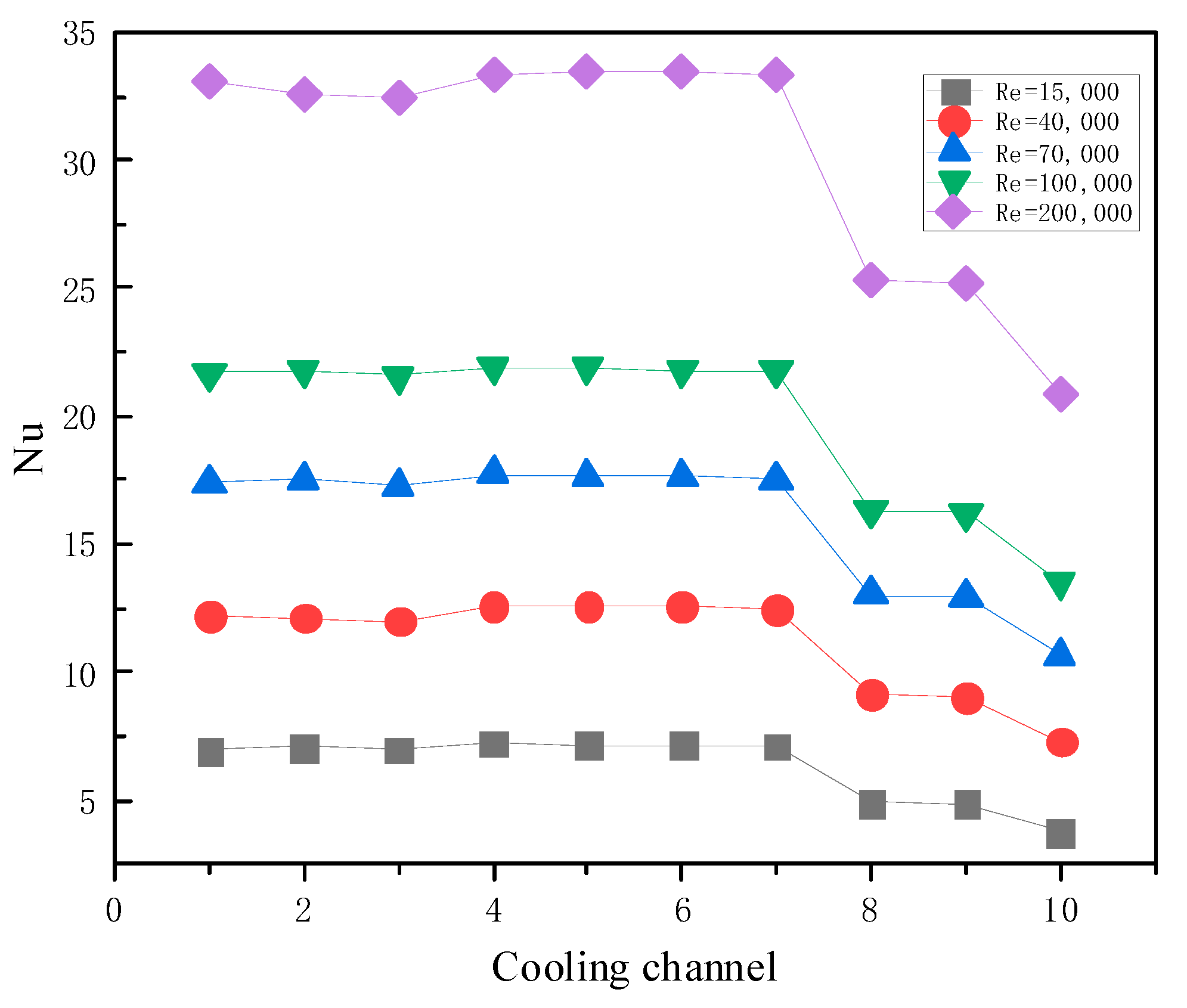
The larger the Re at the entrance of the cooling channel, the larger the average Nusselt number on the wall of the cooling channel; that is, the better the enhanced heat transfer effect of liquid metal gallium. The Peclet number is also an important index for heat transfer quality.
(4)
With an increase in Ga inlet temperature, the average heat transfer coefficient of the cooling channel wall presents a weak rise. The enhanced heat transfer quality factor M lm can reveal the essence.

Author Contributions

Conceptualization, Z.Z. and X.L.; methodology, Z.Z. and Z.W.; software, Z.Z.; validation, Z.Z.; formal analysis, Z.Z. and X.L.; investigation, Z.Z., X.L. and W.L.; resources, Z.Z.; data curation, Z.Z. and W.L.; writing—original draft preparation, Z.Z.; writing—review and editing, Z.W., X.L. and W.L. All authors have read and agreed to the published version of the manuscript.

Funding

This research received no external funding.

Data Availability Statement

The data presented in this study are available on request from the corresponding author. The data are not publicly available due to privacy.

Conflicts of Interest

The authors declare no conflict of interest.

Nomenclature

hheat transfer coefficient (W/(m2∙K))
ReReynolds number
NuNusselt number
PrPrandtl number
ppressure (Pa)
Cpspecific heat capacity (J/(kg·K))
Haverage heat transfer coefficient (W/(m2∙K))
dpipe diameter (mm)
Menhanced heat transfer quality factor
TKelvin temperature (K)
qheat flux
Aheat transfer area (m2)
uvelocity in x direction (m/s)
vvelocity in y direction (m/s)
wvelocity in z direction (m/s)
xCartesian coordinate (m)
yCartesian coordinate (m)
zCartesian coordinate (m)
Greek symbols
λheat conductivity coefficient (W/(m∙K))
δthickness (mm)
ηdynamic viscosity (Pa·s)
ρdensity (kg/m3)
λfthermal conductivity (W/(m·K))
Subscripts
ghigh-temperature gas
ccooling medium
wwall
refqualitative
lmliquid metal

References

  1. Han, J.-C.; Dutta, S.; Ekkad, S. Gas Turbine Heat Transfer and Cooling Technology; CRC Press: Boca Raton, FL, USA, 2012. [Google Scholar]
  2. Boyce Meherwan, P. Gas Turbine Engineering Handbook; Elsevier: Amsterdam, The Netherlands, 2012; pp. 693–719. [Google Scholar]
  3. Bunker, R. Innovative gas turbine cooling techniques. In WIT Transactions on State-of-the-Art in Science and Engineering; WIT Press: Southampton, UK, 2008; Volume 42, pp. 199–229. [Google Scholar]
  4. Kumar, S.; Amano, R.S. An Investigation in the Numerical Approach to Solve the Heat Transfer Phenomenon in Gas Turbine. J. Energy Resour. Technol. 2021, 143, 080805. [Google Scholar] [CrossRef]
  5. Han, J.C. Heat Transfer and Friction Characteristics in Rectangular Channels With Rib Turbulators. J. Heat Transf. 1988, 110, 321–328. [Google Scholar] [CrossRef]
  6. Han, J.C. Heat Transfer and Friction in Channels With Two Opposite Rib-Roughened Walls. J. Heat Transf. 1984, 106, 774–781. [Google Scholar] [CrossRef]
  7. Elfert, M.; Schroll, M.; Förster, W. PIV Measurement of Secondary Flow in a Rotating Two-Pass Cooling System with an Improved Sequencer Technique. J. Turbomach. 2011, 134, 031001. [Google Scholar] [CrossRef]
  8. Zhang, H.; Wang, J.; Wu, X.; Lu, H. A Simplified Approach to Design Transverse Ribs Which Array Alternately in Rectangular Channel. In Proceedings of the ASME Turbo Expo 2010: Power for Land, Sea, and Air, Glasgow, UK, 14–18 June 2010; pp. 197–203. [Google Scholar]
  9. Salameh, T.; Sunden, B. Effects of Ribs on Internal Blade-Tip Cooling. In Proceedings of the ASME 2011 Turbo Expo: Turbine Technical Conference and Exposition, 2011, Vancouver, BC, Canada, 6–10 June 2011; pp. 1033–1041. [Google Scholar]
  10. Gao, Z.; Narzary, D.P.; Han, J.-C. Film cooling on a gas turbine blade pressure side or suction side with axial shaped holes. Int. J. Heat Mass Transf. 2008, 51, 2139–2152. [Google Scholar] [CrossRef]
  11. Walters, D.K.; Leylek, J.H. A Detailed Analysis of Film–Cooling Physics: Part I—Streamwise Injection with Cylindrical Holes. In Proceedings of the ASME 1997 International Gas Turbine and Aeroengine Congress and Exhibition, Orlando, FL, USA, 2–5 June 1997. [Google Scholar]
  12. McGovern, K.T.; Leylek, J.H. A Detailed Analysis of Film Cooling Physics: Part II—Compound–Angle Injection with Cylindrical Holes. In Proceedings of the ASME 1997 International Gas Turbine and Aeroengine Congress and Exhibition, Orlando, FL, USA, 2–5 June 1997. [Google Scholar]
  13. Hyams, D.G.; Leylek, J.H. A Detailed Analysis of Film Cooling Physics: Part III—Streamwise Injection with Shaped Holes. In Proceedings of the ASME 1997 International Gas Turbine and Aeroengine Congress and Exhibition, Orlando, FL, USA, 2–5 June 1997. [Google Scholar]
  14. Kim, Y.J.; Kim, S.M. Influence of shaped injection holes on turbine blade leading edge film cooling. Int. J. Heat Mass Transf. 2004, 47, 245–256. [Google Scholar] [CrossRef]
  15. Cho, H.H.; Rhee, D.H.; Kim, B.G. Enhancement of Film Cooling Performance Using a Shaped Film Cooling Hole with Compound Angle Injection. JSME Int. J. Ser. B Fluids Therm. Eng. 2001, 44, 99–110. [Google Scholar] [CrossRef] [Green Version]
  16. Gritsch, M.; Colban, W.; Schär, H.; Döbbeling, K. Effect of Hole Geometry on the Thermal Performance of Fan-Shaped Film Cooling Holes. J. Turbomach. 2005, 127, 718–725. [Google Scholar] [CrossRef]
  17. Kim, S.-M.; Lee, K.-D.; Kim, K.-Y. A comparative analysis of various shaped film-cooling holes. Heat Mass Transf. 2012, 48, 1929–1939. [Google Scholar] [CrossRef]
  18. Kusterer, K.; Elyas, A.; Bohn, D.; Sugimoto, T.; Tanaka, R.; Kazari, M. The NEKOMIMI Cooling Technology: Cooling Holes With Ears for High-Efficient Film Cooling. In Proceedings of the ASME 2011 Turbo Expo: Turbine Technical Conference and Exposition, Vancouver, BC, Canada, 6–10 June 2011; pp. 303–313. [Google Scholar]
  19. Lee, K.-D.; Kim, K.-Y. Shape optimization of a fan-shaped hole to enhance film-cooling effectiveness. Int. J. Heat Mass Transf. 2010, 53, 2996–3005. [Google Scholar] [CrossRef]
  20. Lee, K.-D.; Kim, K.-Y. Surrogate based optimization of a laidback fan-shaped hole for film-cooling. Int. J. Heat Fluid Flow 2011, 32, 226–238. [Google Scholar] [CrossRef]
  21. Bo, G.Y.; Ren, L.; Xu, X.; Du, Y.; Dou, S.X. Recent progress on liquid metals and their applications. Adv. Phys.-X 2018, 3, 411–441. [Google Scholar] [CrossRef] [Green Version]
  22. Deng, Y.; Jiang, Y.; Liu, J. Low-melting-point liquid metal convective heat transfer: A review. Appl. Therm. Eng. 2021, 193, 117021. [Google Scholar] [CrossRef]
  23. Liu, J. Advanced Liquid Metal Cooling for Chip, Device and System. In Advanced Liquid Metal Cooling for Chip, Device and System; World Scientific Publishers: Singapore, 2020. [Google Scholar]
  24. Liu, G.L.; Liu, J. Convective Cooling of Compact Electronic Devices via Liquid Metals with Low Melting Points. J. Heat Transf. 2021, 143, 050801. [Google Scholar] [CrossRef]
  25. Liu, J.; Zhou, Y.-X.; Lv, Y.-G.; Li, T. Liquid Metal Based Miniaturized Chip-Cooling Device Driven by Electromagnetic Pump. In Proceedings of the ASME 2005 International Mechanical Engineering Congress and Exposition, Orlando, FL, USA, 5–11 November 2005; pp. 501–510. [Google Scholar]
  26. Ma, K.Q.; Liu, J. Heat-driven liquid metal cooling device for the thermal management of a computer chip. J. Phys. D Appl. Phys. 2007, 40, 4722–4729. [Google Scholar] [CrossRef]
  27. Deng, Y.-G.; Liu, J.; Zhou, Y.-X. Study on Liquid Metal Cooling of Photovoltaic Cell. In Inaugural US-EU-China Thermophysics Conference-Renewable Energy 2009 (UECTC 2009 Proceedings); Tao, Y., Ma, C., Eds.; ASME Press: New York, NY, USA, 2009; Volume 1. [Google Scholar]
  28. Pacio, J.; Singer, C.; Wetzel, T.; Uhlig, R. Thermodynamic evaluation of liquid metals as heat transfer fluids in concentrated solar power plants. Appl. Therm. Eng. 2013, 60, 295–302. [Google Scholar] [CrossRef]
  29. Frazer, D.; Stergar, E.; Cionea, C.; Hosemann, P. Liquid Metal as a Heat Transport Fluid for Thermal Solar Power Applications. Energy Procedia 2014, 49, 627–636. [Google Scholar] [CrossRef] [Green Version]
  30. Fritsch, A.; Flesch, J.; Geza, V.; Singer, C.; Uhlig, R.; Hoffschmidt, B. Conceptual Study of Central Receiver Systems with Liquid Metals as Efficient Heat Transfer Fluids. Energy Procedia 2015, 69, 644–653. [Google Scholar] [CrossRef] [Green Version]
  31. Deng, Y.; Liu, J. A liquid metal cooling system for the thermal management of high power LEDs. Int. Commun. Heat Mass Transf. 2010, 37, 788–791. [Google Scholar] [CrossRef]
  32. Peng, H.; Guo, W.; Li, M.; Feng, S. Melting behavior and heat transfer performance of gallium for spacecraft thermal energy storage application. Energy 2021, 228, 120575. [Google Scholar] [CrossRef]
  33. Cheng, K.; Xu, J.; Dang, C.; Qin, J.; Jing, W. Performance evaluation of fuel indirect cooling based thermal management system using liquid metal for hydrocarbon-fueled scramjet. Energy 2022, 260, 125068. [Google Scholar] [CrossRef]
  34. Zhang, X.-D.; Yang, X.-H.; Zhou, Y.-X.; Rao, W.; Gao, J.-Y.; Ding, Y.-J.; Shu, Q.-Q.; Liu, J. Experimental investigation of galinstan based minichannel cooling for high heat flux and large heat power thermal management. Energy Convers. Manag. 2019, 185, 248–258. [Google Scholar] [CrossRef]
  35. Al Omari, S.A.B.; Haik, Y.; Abu Jdayil, B. Flow characteristics of gallium in a meso-scale channel under the influence of magnetic fields. Int. Commun. Heat Mass Transf. 2010, 37, 1127–1134. [Google Scholar] [CrossRef]
  36. Al Omari, S. Characteristics of the flow and heat transfer of gallium in a mini-scale channel under the effect of magnetic field. J. Enhanc. Heat Transf. 2011, 18, 537–546. [Google Scholar] [CrossRef]
  37. Kang, S.; Ha, K.-S.; Kim, H.T.; Kim, J.H.; Bang, I.C. An experimental study on natural convection heat transfer of liquid gallium in a rectangular loop. Int. J. Heat Mass Transf. 2013, 66, 192–199. [Google Scholar] [CrossRef]
  38. Omari, S.A.B.A.; Elnajjar, E. An Experimental Study on Enhancing Cooling Rates of Low Thermal Conductivity Fluids Using Liquid Metals. Fluid Dyn. Mater. Process. 2013, 9, 91–109. [Google Scholar]
  39. Manservisi, S.; Menghini, F. A CFD four parameter heat transfer turbulence model for engineering applications in heavy liquid metals. Int. J. Heat Mass Transf. 2014, 69, 312–326. [Google Scholar] [CrossRef]
  40. Sharma, D.; Singh, P.P.; Garg, H. Comparative Study of Rectangular and Trapezoidal Microchannels Using Water and Liquid Metal. Procedia Eng. 2013, 51, 791–796. [Google Scholar] [CrossRef] [Green Version]
  41. Tawk, M.; Avenas, Y.; Kedous-Lebouc, A.; Petit, M. Numerical and Experimental Investigations of the Thermal Management of Power Electronics With Liquid Metal Mini-Channel Coolers. IEEE Trans. Ind. Appl. 2013, 49, 1421–1429. [Google Scholar] [CrossRef]
  42. Zhang, X.-D.; Gao, J.-Y.; Liu, J. Comparative Study of Heat Transfer in a Mini/Micro Pipe with Water and Liquid Metal As Fluid. In Proceedings of the ASME 2020 Heat Transfer Summer Conference collocated with the ASME 2020 Fluids Engineering Division Summer Meeting and the ASME 2020 18th International Conference on Nanochannels, Microchannels, and Minichannels, Virtual, Online, 13–15 July 2020. [Google Scholar]
  43. Wu, T.; Wang, L.; Tang, Y.; Yin, C.; Li, X. Flow and Heat Transfer Performances of Liquid Metal Based Microchannel Heat Sinks under High Temperature Conditions. Micromachines 2022, 13, 95. [Google Scholar] [CrossRef] [PubMed]
  44. Hojna, A.; Di Gabriele, F.; Klecka, J. Character of Liquid Metal Embrittlement of the Steel T91 in Contact with Lead-Bismuth Eutectic. In Proceedings of the 2014 22nd International Conference on Nuclear Engineering, Prague, Czech Republic, 7–11 July 2014. [Google Scholar]
  45. Cui, Y.; Ding, Y.; Xu, S.; Wang, Y.; Rao, W.; Liu, J. Study on Heat Transfer and Corrosion Resistance of Anodized Aluminum Alloy in Gallium-Based Liquid Metal. J. Electron. Packag. 2019, 141, 011001. [Google Scholar] [CrossRef]
  46. Miner, A.; Ghoshal, U. Cooling of high-power-density microdevices using liquid metal coolants. Appl. Phys. Lett. 2004, 85, 506–508. [Google Scholar] [CrossRef]
  47. Pacio, J.; Marocco, L.; Wetzel, T. Review of data and correlations for turbulent forced convective heat transfer of liquid metals in pipes. Heat Mass Transf. 2015, 51, 153–164. [Google Scholar] [CrossRef]
  48. Hylton, L.; Mihelc, M.; Turner, E.; Nealy, D.; York, R. Analytical and Experimental Evaluation of the Heat Transfer Distribution over the Surfaces of Turbine Vanes; NASA: Washington, DC, USA, 1983. [Google Scholar]
  49. Menter, F.; Kuntz, M.; Langtry, R.B. Ten years of industrial experience with the SST turbulence model. Heat Mass Transf. 2003, 4, 625–632. [Google Scholar]
  50. Dong, P.; Wang, Q.; Guo, Z.; Huang, H.; Feng, G. Conjugate Calculation of Gas Turbine Vanes Cooled with Leading Edge Films. Chin. J. Aeronaut. 2009, 22, 145–152. [Google Scholar] [CrossRef] [Green Version]
  51. Bagabir, A.; Drikakis, D. Mach number effects on shock-bubble interaction. Shock Waves 2001, 11, 209–218. [Google Scholar] [CrossRef]
  52. Larsson, J.; Bermejo-Moreno, I.; Lele, S. Reynolds- and Mach-number effects in canonical shock-turbulence interaction. J. Fluid Mech. 2013, 717, 293–321. [Google Scholar] [CrossRef]
  53. Johnson, H.A.; Hartnett, J.P.; Clabaugh, W.J. Heat Transfer to Molten Lead-Bismuth Eutectic in Turbulent Pipe Flow. J. Heat Transf. 1953, 75, 1191–1198. [Google Scholar] [CrossRef]
  54. Cheng, X.; Tak, N.-I. Investigation on turbulent heat transfer to lead–bismuth eutectic flows in circular tubes for nuclear applications. Nucl. Eng. Des. 2006, 236, 385–393. [Google Scholar] [CrossRef]
  55. Lyon, R.N. Liquid metal heat transfer coefficients. Chem. Eng. Prog. 1951, 47, 269. [Google Scholar]
  56. International Atomic Energy Agency. Comparative Assessment of Thermophysical and Thermohydraulic Characteristics of Lead, Lead-Bismuth and Sodium Coolants for Fast Reactors; International Atomic Energy Agency: Vienna, Austria, 2002. [Google Scholar]
Figure 1. One-dimensional thermal conductivity calculation for guide vane cooling of high-pressure turbines.
Aerospace 10 00548 g001
Figure 2. Geometric configuration and computational grid.
Aerospace 10 00548 g002
Figure 3. Wall temperature distribution of vane mid-diameter.
Aerospace 10 00548 g003
Figure 4. Heat transfer coefficient distribution of vane mid-diameter.
Aerospace 10 00548 g004
Figure 5. Contour images of temperature distribution on the vane outer wall.
Aerospace 10 00548 g005
Figure 6. Temperature distribution of 10%, 50%, and 90% vane height sections.
Aerospace 10 00548 g006
Figure 7. Temperature distribution of 10%, 50%, and 90% vane height sections.
Aerospace 10 00548 g007
Figure 8. Temperature distribution of 50% vane height section under different working media: (a) air; (b) gallium.
Aerospace 10 00548 g008
Figure 9. External wall temperature distribution at 50% vane height under different working media.
Aerospace 10 00548 g009
Figure 10. Wall heat transfer coefficient distribution of different cooling channels on vanes.
Aerospace 10 00548 g010
Figure 11. Nondimensional temperature gradient distribution of air and gallium in a section: (a) air; (b) gallium.
Aerospace 10 00548 g011
Figure 12. Average Nusselt number distribution on cooling channel wall under different cooling channel inlet Re values.
Aerospace 10 00548 g012
Figure 13. Comparison of the numerical simulation results with the variation in Nu number with Pe number in different studies in the literature [53,54,55,56].
Aerospace 10 00548 g013
Figure 14. Average heat transfer coefficient distribution of cooling channel wall at different Ga inlet temperatures.
Aerospace 10 00548 g014
Table 1. Boundary conditions for one-dimensional thermal conductivity calculation.
Hot GasTurbine Guide VaneCooling Medium
CoatingMetal Material
T g h g λ 1 δ 1 λ 2 δ 2 T c
2400
K
8000
W/(m2∙K)
0.5
W/(m∙K)
0.125
mm
26
W/(m∙K)
3.55
mm
700
K
Table 2. Heat transfer coefficient and maximum temperature of vane metal material when air or gallium is used as the cooling working medium.
Cooling MediumHeat Transfer Coefficient h / W / m 2 K Metal Material Temperature T w /K
Air20001769
Gallium98,4001174
Table 3. Boundary conditions of main flow gas of Mark II vane.
Inlet ConditionsTotal Inlet Pressure/Pa337,097
Total Inlet Temperature/K2400
Outlet conditionsOutlet static pressure/Pa175,713
Table 4. Boundary conditions of Mark II vane cooling passages.
Cooling ChannelDiameter/mmInlet Mass Flow Rate/kg/sTin/KPout/MPa
16.30.02463260.3533
26.30.02373160.3497
36.30.02383220.3571
46.30.02473280.3647
56.30.02333080.3200
66.30.02283050.3428
76.30.02383130.3587
83.10.007753350.7030
93.10.005113300.5370
101.980.003343541.0199
Table 5. Calculation results of grid-independent solutions.
Grid Number/Ten Thousand90100118200400
Mainstream outlet average temperature/K677.0677.1676.6677.3676.5
Table 6. Reynolds number analysis to calculate the condition.
Working ConditionCondition 1Condition 2Condition 3Condition 4Condition 5
Cooling channel inlet Reynolds number Re15,00040,00070,000100,000200,000
Table 7. Inlet speeds of different cooling channels.
Cooling Channel Pipe Diameter/(mm)6.33.11.98
Cooling channel inlet velocity/(m/s)3.346
Table 8. Inlet temperature analysis and calculation conditions.
Working ConditionCondition 1Condition 2Condition 3Condition 4Condition 5
Inlet temperature/K310320330340350
Table 9. Enhanced heat transfer quality factor M lm at different temperatures.
Temperature/K310320330340350
M lm × 10 10 3.733.843.944.054.15
Disclaimer/Publisher’s Note: The statements, opinions and data contained in all publications are solely those of the individual author(s) and contributor(s) and not of MDPI and/or the editor(s). MDPI and/or the editor(s) disclaim responsibility for any injury to people or property resulting from any ideas, methods, instructions or products referred to in the content.

