Abstract
Recent studies have revealed that control surface deflection can cause a reduction in the aerodynamic efficiency of a hypersonic aircraft of up to 30%. In fact, the characterization of the Flight Control System is essential for the estimation of the consistent aerodynamic characteristics of the vehicle in different phases, considering the contribution of control surfaces to stability and trim. In terms of the sizing process, traditional methodologies have been demonstrated to be no longer applicable to estimations of the actuation power required for the control surfaces of a high-speed aircraft, due to their peculiar working conditions and to the characteristics of the flow to which they are exposed. In turn, numerical simulation approaches based on computational fluid dynamics or panel methods may require considerable time resources, which do not fit with the needs of the quick and reliable estimates that are typical of the early design phases. Therefore, this paper is aimed at describing a methodology to show how to anticipate the Flight Control System design for high-speed vehicles at the conceptual design stage, properly considering the interactions at vehicle level and predicting the behavior of the system throughout an entire mission. It is also a core part of the work to provide designers with an example of how neglecting the effect of trim drag can be detrimental to a reliable estimation of overall aircraft performance. The analysis, mainly focused on the longitudinal plane of the vehicle, is presented step-by-step on a specific case study, namely the STRATOFLY MR3 vehicle, a Mach 8 waverider concept for civil antipodal flights. The application of the methodology, conceived as an initial step towards an iterative Flight Control System design process, also shows that the most power-demanding phases are take-off, low supersonic acceleration, and approach, where peaks of over 130 kW are reached, while an average of 20 kW is sufficient to support deflections in a hypersonic cruise.
1. Introduction
The Flight Control System (FCS) is considered a key enabler for future high-speed aircraft and, therefore, the anticipation of its impact on aircraft layout and performance is essential to assess the viability of concepts under development. Preliminary investigations carried out in several high-speed projects [1,2,3,4] highlight that a reduction of about 30%, with respect to the maximum theoretical efficiency of a hypersonic civil aircraft, can be expected due to control surface deflection. Therefore, dealing with the effect of the FCS on the vehicle’s behavior beforehand, since the early stages of design, guarantees a more accurate and realistic aerodynamic characterization, as well as a consequent more reliable estimation of fuel consumption and range performance. In turn, the consistent estimation of fuel consumption is a key element for the evaluation of the environmental impact of the vehicle and mission concepts [2], being also one of the most important parameters for the estimation of the solution’s operating costs [5]. Currently, the attention of the research community to the topic is mainly focused on the development of ad hoc controllers (software) to guarantee proper maneuverability characteristics for these kinds of vehicles (Section 2), neglecting the relevance of an adequate control surfaces characterization during the earliest design phases (hardware). The inadequacy of traditional design methodologies, the interrelationships among the FCS and the other on-board systems, and the need to anticipate as early as possible the geometrical and performance characterization of the FCS during the design of future high-speed vehicles, are the driving factors of this paper, which describes a methodology able to anticipate the design and sizing of FCS at the conceptual design stage. The application of this kind of approach in the early stages of a project lifecycle is a key innovation aspect of the paper, since it points out potential problems related to the evaluation of vehicle performance requirements, which could not be assessed by looking only at a clean configuration (without the impact of control surface deflection). In fact, the range that can potentially be covered by the aircraft during the reference mission is massively influenced by its flight efficiency, bringing together the contribution of aerodynamic efficiency and propulsive efficiency (i.e., fuel consumption). Both aspects are deeply affected by the drag profile characterizing the aircraft during the flight, which could be significantly different in clean configuration and during maneuvers because of the deflection of control surfaces. This is also the major added value of the work, which aims at warning designers not to neglect the trim drag effect during the conceptual design of the vehicle, which risks jeopardizing the mission concept, and at suggesting how to approach the activity both in terms of trim map generation as well as of on-board actuation system characterization. In order to quantitatively demonstrate the potential threats of underestimating trim drag impact, a direct comparison between the aerodynamic efficiency of clean and complete configurations is made on a specific case study, providing the readers with practical order of magnitude and verifying the hypothesis from the previous Literature. Ultimately, the subsequent FCS sizing approach to evaluating the power required to actuate the control surfaces (in order to trim the vehicle) suggests practical numerical results that can be helpful for preliminary evaluation of on-board systems’ power demands. After this brief introduction, an overview of the studies on FCS design for high-speed vehicles is presented, to clearly define the gaps existing in the scientific Literature on the topic, as well as to identify useful background for the development of the methodology (Section 2). Then, Section 3 briefly presents the STRATOFLY MR3 hypersonic cruiser, a European Mach 8 waverider concept for civil antipodal flights, used as case study, together with the reference mission. Section 4 reports the integrated FCS characterization approach specifically devised for high-speed vehicles in conceptual design. The theoretical design process is presented step-by-step, in conjunction with the application to the specific case study, with particular focus on the longitudinal plane of the vehicle. Ultimately, Section 5 draws major conclusions about the work, which is conceived as an initial step towards complete FCS design, usually faced through multiple iterations.
2. Studies on Flight Control System Design for High-Speed Vehicles
As the attraction of high-speed vehicles grows, the scientific Literature reveals a noticeable attention to the guidance and control of such innovative transportation systems. However, it is worth noting that many recent works focus on the controller design (software), rather than on the design and characterization of the flight control surfaces and actuation subsystem (hardware). Primarily, it is important to highlight that traditional system design methodologies are not directly applicable to innovative aircraft design, as widely addressed in the Literature [6,7,8,9,10,11]. It is clear that a paradigm shift in systems design methodology is necessary to deal with the next generation of high-speed vehicles. First of all, systems design methodologies available in the Literature, such as the well-known Roskam [12], Torenbeek [13], Raymer [14], and the more recent Sadraey [15], consider each system as standalone, and possible interactions with other on-board plants are accounted for only during the detailed design phases. This simplification is acceptable for subsonic aircraft, with old-fashioned system architecture, where each high-level function is specifically allocated onto a well-defined item. However, this is not the case for the future generation of high-speed vehicles [7,8,9,10,11]. Indeed, both supersonic and hypersonic transportation systems are characterized by a high-level of integration, both from the aero-thermo-propulsive standpoint, as well as from the system one [16]. Moreover, this degree of integration at the system level is twofold. On one hand, there are clear examples of multifunctional systems, which integrate, in specific physical elements, more than a single high-level capability. On the other hand, in order to reach the expected unprecedented performance target, it is essential to increase interactions among the various on-board systems. This is the case of FCS, whose design and sizing shall consider the strict relationship with the vehicle’s aerothermal characterization [4,17,18] and the propellant system definition [19]. Indeed, when following classical conceptual design methodologies, the impact of control surface deflection on the aircraft’s aerodynamic characterization can be neglected during the early stage of design without extreme penalties. This can be acceptable for subsonic aircraft with traditional wing–fuselage architecture, whilst it cannot be applied to the case of high-speed aircraft, mostly characterized by unconventional and blended configurations, including waverider concepts. As clearly shown in [4], the impact of control surface deflection can noticeably affect the aerodynamic performance of the entire vehicle. Therefore, the FCS design methodology shall be supported by a first indication of the effect of each control surface’s contribution throughout the mission profile. This preliminary estimation paves the way for the integration of stability and trim analyses and, consequently, for a more accurate prediction of propellant consumption and a more consistent propellant system definition, as well [19]. Additionally, preliminary system design algorithms often consider the cruise as a sizing condition for most of the on-board plants, including the FCS. This assumption may fit the case of subsonic aircraft, but it is not representative for supersonic and hypersonic aircraft, as already demonstrated in [7,8,9,10,11,17,18]. Depending on the vehicle configuration and mission, subsonic flight conditions (such as take-off and landing) can be as demanding for the FCS as those characterizing the high-speed cruise. Therefore, a proper FCS design methodology shall include a quick estimation of the actuation power required in each different mission phase, thus allowing for an adequate selection of the reference sizing condition. Lastly, systems design traditionally pertains to the preliminary design phase, thus it uses the results of the conceptual design phase as input. However, this waterfall approach is hardly applicable to the design of systems for highly integrated vehicle concepts, where each on-board element has an evident impact on the vehicle and mission. Therefore, the conceptual design methodology suggested in this paper adopts an agile approach, which encourages fast iterations involving different design levels and a degree of accuracy which incrementally increases through each iteration.
3. STRATOFLY MR3 Vehicle and Mission Concepts
STRATOFLY MR3 is a European Mach 8 waverider concept for civil antipodal flights conceived under the H2020 STRATOFLY project [2]. The MR3 is a highly integrated vehicle where propulsion, aerothermodynamics, structures, and on-board systems are strictly interrelated with each other (Figure 1), offering a valuable case study to show off the methodology proposed in this paper. In the first part of the project, conceptual design methods and tools have been used in a preliminary assessment of mass, volume, and power budgets following a top-down approach [2]. Subsequently, in the second part of the project, those analyses have been verified through the design, sizing, and integration of each system. The vehicle is designed to have a Maximum Take-Off Mass (MTOM) of about 400 tons, hosting 300 passengers for a total payload capacity of 33 tons and an empty mass of around 187 tons. The reference planform surface is around 2500 and the total internal volume is close to 10,000 . Looking inside the vehicle, the use of a bubble structure has successfully demonstrated to guarantee a lightweight airframe with multi-functional roles, such as the passenger cabin, multiple split tanks with anti-slosh baffles, engine bays, and intake flow-paths, contributing to the integration of all on-board systems in a harmonious way [20,21]. Liquid hydrogen has been selected as propellant, thanks to its high specific energy content, which allows the vehicle to cover antipodal routes flying at Mach 8 without emitting any CO2. Particularly, the STRATOFLY MR3 vehicle was originally conceived to cover missions featuring a global distance of around 18,000 km. A first mission analysis was carried out to identify a draft trajectory and profile (Figure 2), connecting Brussels to Sydney, as described here. During the first part of the mission, six Air Turbo Rocket (ATR) engines are used [22], with an available thrust at sea level of about 233 kN per engine. The vehicle flies at subsonic speeds during the subsonic climb. Then, the acceleration up to around Mach 0.90 is supposed to take place, reaching an altitude between 11 km and 13 km. At this point, the vehicle performs the subsonic cruise. This phase is needed to avoid a sonic boom [23] while flying over land. A constraint on the distance flown from the departure site is introduced to fulfil this requirement. In fact, the subsonic cruise phase ends when the vehicle is 400 km from the departure airport. During the next phase, the vehicle performs a second climb, until reaching Mach 4 (supersonic climb). At the end of this phase, the ATR engines are turned off and the Dual Mode Ramjet (DMR) [24] is activated to accelerate up to Mach 8, reaching an altitude of 32–33 km (hypersonic climb). Here, the cruise starts at Mach 8, with a total thrust of 664 kN available for the DMR. During the first part of the cruise, the vehicle flies over the arctic region towards the Bering strait, between Asia and North America. Then, the vehicle continues to cruise over the Pacific Ocean towards Sydney. The waypoint at which the cruise phase is concluded depends on the type of descent considered, i.e., powered or gliding descent. The first mission concept developed within the precursor LAPCAT II Project [25] involved a gliding descent [26]. However, since the aerodynamic performance is supposed to be very low in engine-off conditions, a powered descent has been considered for an updated mission concept. The sketch provided in Figure 2 is just a first mission layout, while the final performance over the reference mission, in terms of fuel consumption and aerodynamic efficiency, will be updated after introducing the control surfaces and fuel depletion strategy.
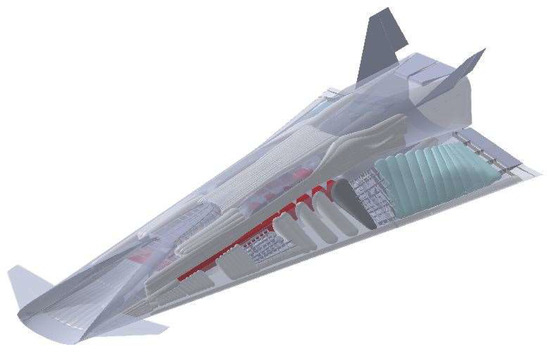
Figure 1.
STRATOFLY MR3 Vehicle layout with integrated systems.

Figure 2.
Overview of trajectory and mission profile BRU-SYD.
4. Flight Control System Integrated Design Methodology
4.1. Methodology Overview
As highlighted in the introduction, preliminary investigations [1,2,3,4] already state that a reduction of about 30% with respect to the maximum theoretical efficiency of a hypersonic civil aircraft can be expected due to control surface deflection. In this context, a valuable integrated system design methodology (Figure 3) shall introduce the FCS in the design loop as soon as a first external aircraft layout, together with aerodynamic and propulsive characteristics, is available. On this basis, a preliminary mission analysis shall be carried out to identify a viable flight trajectory and to verify the behavior of the clean vehicle concept (no control surfaces) throughout the mission. Indeed, for high-speed vehicle design, it is essential to check the major aerodynamic and propulsive characteristics not only in cruise conditions, but also in off-design conditions, i.e., at subsonic and low supersonic speed regimes, to ensure the feasibility of the concept. Once a first conceptual design loop is completed, it is the proper time to introduce the analysis of the FCS, starting with the geometrical characterization of empennages and related movable surfaces. A few promising semi-empirical models for control surfaces’ geometrical definitions are available in the Literature (mainly for conventional aircraft), making use of volumetric ratios as main design parameters [14,15]. These simplified semi-empirical models are very useful to geometrically define the chords and widths of each control surface and for the consequent evaluation of the distance between their aerodynamic center and the center of the entire vehicle, allowing also for the evaluation of their contribution on stability. Once all control surfaces are defined, it is essential to estimate their maximum deflections. In this case, as far as high-speed aircraft are concerned, it is essential to estimate the minimum deflections required to meet trim requirements throughout the mission. It is at this stage that the interaction with a second loop of conceptual design is necessary, taking into consideration also the integration of inputs coming from the preliminary investigation of propellant and avionic systems. The newly defined surfaces can be analyzed in detail with low- or high-fidelity aerodynamic tools to predict their single contribution to the vehicle lift and drag coefficients. According to [4], the effect of control surface deflection can be estimated through inviscid calculations applied to simplified configurations where standalone or integrated simulations can be performed. The contribution of the control surfaces is thus evaluated with respect to the clean configuration case, as carried out during the first loop of conceptual design. The upgraded aerodynamic characterization can be then exploited for a second mission analysis, where the vehicle trim conditions are estimated for each time interval. At this stage, the interaction with the propellant system design and avionics becomes crucial. Indeed, trim conditions strongly depend on the position of the aircraft’s center of gravity, of which the variation along a long-haul hypersonic mission cannot be neglected. Therefore, in parallel to the definition of final control surface deflections, it is essential to study and implement a proper tank distribution and depletion strategy to minimize control surface movements, thus reducing the detrimental effect on the overall aerodynamic efficiency (trim drag) of the aircraft. Moving on to consider the actuation system, the maximum required control surface deflections are used as inputs for the estimation of hinge moments. A novel approach is suggested in the following subsections to extend the formulations available in the Literature [6] beyond the transonic regime. In the end, the FCS design is completed with the selection of actuators and finalization of the system architecture, both in terms of power distribution lines and control logics, respectively, considering interactions with and connections with the electrical power system and avionic system. This would theoretically allow to produce a first sketch schematic of the system in terms of data and power flows for subsequent evaluations. Figure 3 graphically summarizes the FCS design methodology highlighting the couplings with the other on-board systems, as well as with the vehicle’s propulsive and aerodynamic characteristics.
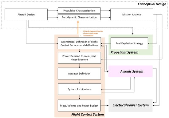
Figure 3.
Integrated FCS design methodology.
For the sake of clarity, the methodology summarized above is hereafter theoretically presented step-by-step, supporting the theoretical investigations with the practical application to the MR3 case study.
4.2. Step 1: Geometrical Definition of Flight Control Surfaces
The possible entry point of this iterative and recursive methodology, once vehicle layout and mission profile are defined, is the preliminary geometrical characterization of the control surfaces. According to [27], it is theoretically possible to identify some configuration-related ratios between movable and reference lifting surfaces. Considering the class of the vehicle, its peculiar architecture and previous studies on the topic, values associated with [28] have been considered for the selected case study, as reported in Table 1. To compute the required control device areas, the total aircraft footprint (2500 ) is here considered as a reference surface for the MR3 case study.

Table 1.
Initial evaluation of movable surfaces dimensions based on the Literature.
Then, a proper comparison with the surfaces designed for the precursor LAPCAT MR2.4 vehicle [25] was performed to check the relevance of the aforementioned ratios (Table 2).

Table 2.
LAPCAT MR2.4 control surfaces.
Even though trailing edge surfaces can be used for both pitch and roll control (elevons), in this case their contribution has been allocated to roll because of their reduced size, meeting the roll control surface requirement only. Overall, results appear in line with the expectations (Table 1), even though a higher surface for longitudinal control could be beneficial. For this reason, the consolidated MR3 aircraft layout includes a fully movable canard, four elevons, two body flaps placed on top of the integrated nozzle, and a pair of V-shaped rudders (Figure 4) (Table 3). Body flaps have been enlarged even more than the required value to increase the longitudinal control margin. However, a reduction in the lateral control surface (rudders) was required to avoid interference during operation. The effect on lateral plane characteristics is not evaluated in this work, but the authors highlight that this topic shall be further assessed (only reference power demand for rudders is hypothesized in Section 4.5).
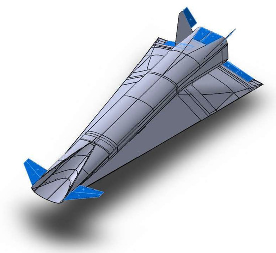
Figure 4.
STRATOFLY MR3 Control Surfaces.

Table 3.
Control surfaces characterization for MR3 (data for single surface—one side for each category).
4.3. Step 2: Stability Analysis for the Clean Configuration
Once control surfaces have been characterized according to this approach, a preliminary verification of their effect on longitudinal stability can be performed. In general, the longitudinal static stability can be verified if the pitching moment coefficient CMy (Equation (1)) has a decreasing trend for an increasing Angle of Attack (AoA, defined as the angle between the reference longitudinal aircraft axis and the relative wing). It is worth noting that all the subsequent analyses refer to the vehicle angle of attack, already taking into account that the wing sees a higher angle with reference to the incoming flow because of its layout (incidence).
The pitching moment coefficient is evaluated by combining the value of the clean configuration , the individual effect of the flight control surfaces and the additional effect due to the misalignment of the thrust vector with respect to the longitudinal vehicle axis , as in Equation (2):
The assessment on the Center of Gravity (CoG) in this specific case suggests that the variation is expected to occur between 48 m and 53 m [4,25], while the vehicle’s total length is equal to 94 m. The most rearward position is representative of the initial part of the mission, i.e., the fuel tanks are full and the vehicle mass is equal to the MTOM [19]. The forward position is instead reached when the fuel tanks are empty (zero-fuel mass). In order to control the position of the CoG within the aforementioned range, a proper tank depletion strategy is studied (as described in Section 4.4). The trend describing the pitching moment coefficient as a function of the AoA has been evaluated for different Mach numbers and positions of the CoG. The AoA range is limited to −6° < α < 6°, since this kind of vehicle is not supposed to fly at high attitudes. As shown in Equation (2), is the first term to be evaluated (vehicle clean configuration, i.e., the aircraft concept without any flight control surfaces deflected). The results show an unstable behavior at subsonic speeds for Mach numbers between 0.3 and 0.8 and a CoG equal to 53 m (Figure 5), while at Mach 0.95 the pitching moment curve has a negative slope. As far as the forward position of the CoG is considered, the vehicle is stable for the entire subsonic range (Figure 6). For higher Mach numbers, the stability has been verified for both positions of the CoG, as can be seen in Figure 7 and Figure 8. However, the values of the are always below zero, suggesting that there are no trim conditions in the considered range, i.e., for −6° < α < 6°. Therefore, it is clear that flight control surfaces must be included to reach stable and trimmed conditions for the entire Mach range and for the desired set of AoA.
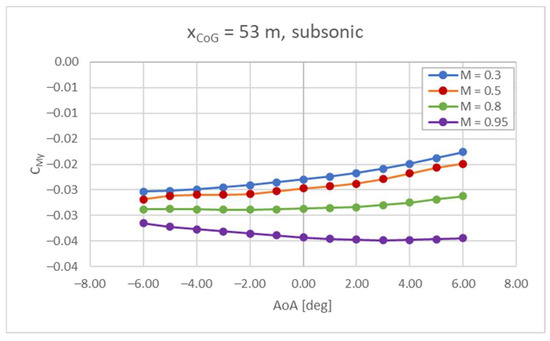
Figure 5.
Cmy vs. AoA at subsonic speed, CoG = 53 m.
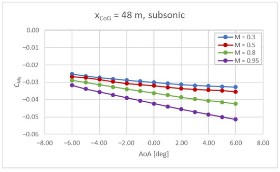
Figure 6.
Cmy vs. AoA at subsonic speed, CoG = 48 m.
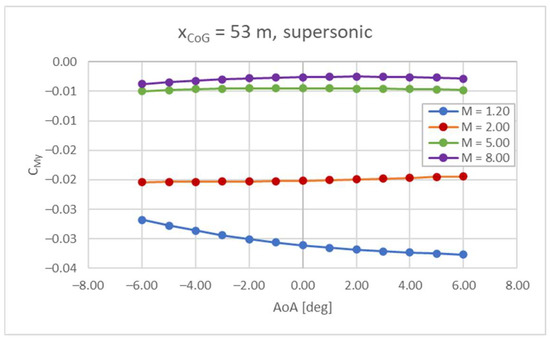
Figure 7.
CMy vs. AoA at supersonic speed, CoG = 53 m.
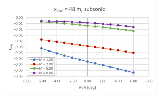
Figure 8.
Cmy vs. AoA at supersonic speed, CoG = 48 m.
4.4. Step 3: Aerodynamic Characterization of Control Surfaces and Trim Analysis
Once the control surface layout is generally defined, the focus shall move to the selection of the most suitable deflections in order to guarantee trim conditions throughout the mission, minimizing the negative impact on overall vehicle efficiency. The complete workflow which leads to the definition of trim conditions along the different flight phases is depicted in Figure 9. For each Mach number and CoG position, all the possible combinations of control surface deflections (, …, ) are considered when analyzing aircraft stability and trim. The overall contribution of control surfaces to the vehicle aerodynamic coefficients (, and ) are then used to evaluate the overall aerodynamic performance of the aircraft. At first, stability is verified by checking if the trend associated to the pitching moment coefficient as a function of the angle of attack is decreasing (). In the range of stable conditions, the trim condition () is detected for , thus . It is worth noting that the same can be achieved with different combinations of control surface deflections. In case of high-speed vehicles, the authors suggest selecting the control surface deflection combination which maximizes the aircraft’s overall aerodynamic efficiency (L/D). Looking at the practical application to the STRATOFLY MR3 vehicle, the control surfaces have been thoroughly investigated from the aerodynamic standpoint to estimate their impact on the overall aerodynamic efficiency of the aircraft. Details of the aerodynamic computations have been published in [4]. Trim analysis is performed considering the flight control surface deflections (, , ) and the position of the CoG at each Mach number, which must be defined a priori.
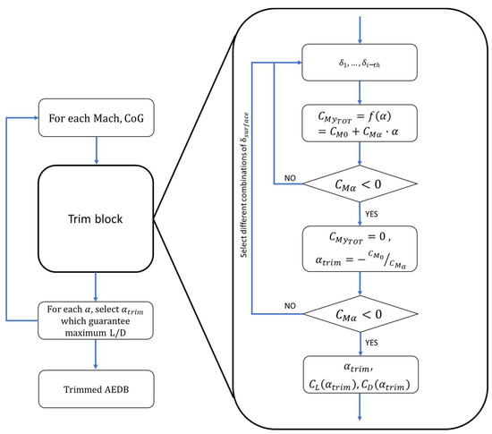
Figure 9.
Workflow for the evaluation of stable and trimmed aerodynamic conditions.
Expanding the terms of Equation (2), it is possible to obtain Equation (3) for the MR3 case study.
It is important to note that for each considered Mach number, the value of the pitching moment coefficient depends on the position of the CoG, which is supposed to change along the mission. In this case, different CoG positions have been considered in the range between 51% (48 m—empty tanks) and 56% (53 m—full tanks) of the vehicle length.
As an example, the algorithm reported in Equation (4) has been used to estimate the minimum body flap deflection that allows to trim the vehicle at a certain flight condition (given Mach and CoG position), simultaneously keeping the other surfaces at a given position.
The first result of this analysis is a set of curves, one for each considered deflection, that can be used to guide the designer in the selection of the best option to trim the vehicle. For the MR3 case study, the minimum required deflection decreases as the CoG position shifts forward. This information is crucial to identifying an optimized propellant depletion strategy, targeting a minimization of the surface deflections [19]. In fact, the body flap deflection sequence has been identified as a driving factor for the identification of the magnitude of the deflections for all surfaces, thus suggesting the best positions for the CoG in different conditions (i.e., when the body flap deflections are high, the other control surfaces will also experience high angles of deflection, and vice versa). The reference CoG shift is reported in Figure 10, as a consequence of the best fuel depletion sequence identified in [19], taking into account trim requirements and looking at minimizing the trim drag effect. The same approach can also be replicated and extended to the other surfaces, including combinations. The result is a set of trim maps for each Mach number.
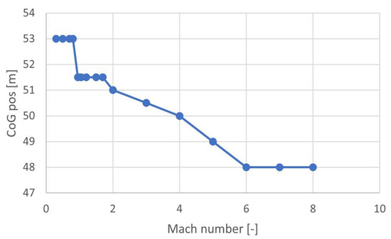
Figure 10.
CoG position as a function of Mach number.
Each 3D map shows the resulting as a function of body flap and elevon deflections for a given Mach number and CoG position. Each canard deflection is reported with a different color. An example of a 3D trim map for subsonic speed (Mach 0.5) is reported in Figure 11. In Figure 11a the body flap deflection is fixed and the angle of attack varies only with the elevon deflection . The 3D and 2D trim maps for Mach number equal to 0.8 are reported in Figure 12. In the subsonic regime, high deflections of the control surfaces are required to trim the vehicle in the considered range. The low-speed regime is the most demanding one in terms of stability and trim, since the CoG is towards the rear of the vehicle and the required to trim the aircraft is higher.
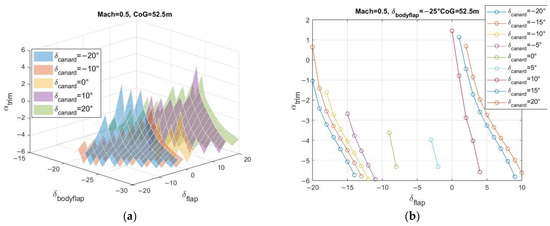
Figure 11.
Trim maps for Mach 0.5 and CoG 52.5 m—(a) 3D, (b) 2D for .
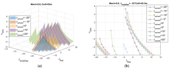
Figure 12.
Trim maps for Mach 0.8 and CoG 52.0 m—(a) 3D, (b) 2D for .
The 3D and 2D maps for the transonic/supersonic regime are reported in Figure 13 for Mach 1.2 and in Figure 14 for Mach 2.
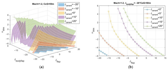
Figure 13.
Trim maps for Mach 1.2 and CoG 50.0 m—(a) 3D, (b) 2D for .
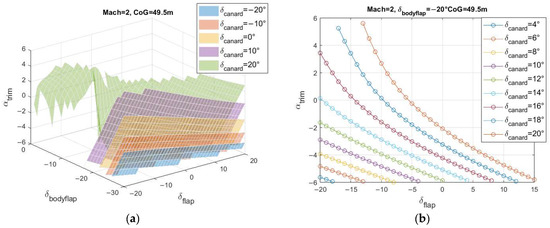
Figure 14.
Trim maps for Mach 2.0 and CoG 49.5 m—(a) 3D, (b) 2D for .
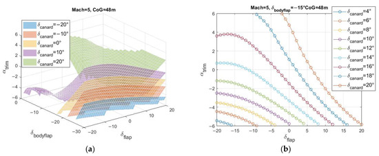
Figure 15.
Trim maps for Mach 5.0 and CoG 48.0 m—(a) 3D, (b) 2D for .
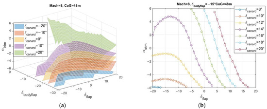
Figure 16.
Trim maps for Mach 8.0 and CoG 48.0 m—(a) 3D, (b) 2D for .
The resulting CL, CD, and L/D, at different Mach numbers and for AoA = 0°, are reported in Figure 17 for the selected cases. The impact of control surface deflection is clearly visible if compared to the clean configuration, especially where it concerns the increase in total drag and, consequently, the decrease in the aerodynamic efficiency along the entire Mach range (Figure 17c). The lowest value of the Lift-to-Drag ratio is found at supersonic speed, in the range from Mach 0.9 to 3, where the L/D decreases to 3.5. Moreover, a preliminary mission simulation has shown that the time required to perform the supersonic climb (i.e., accelerating from Mach 0.95 to Mach 4) can be quite high and could limit the capability of the STRATOFLY MR3 vehicle to cover the antipodal route. For this reason, the solution to relax the stability requirements within this range, taking advantage of the modern, robust, and fast guidance equipment, has been hypothesized. To check the practical advantage of this approach, the constraint on longitudinal static stability is removed for those phases and the trim conditions are evaluated again in this range, considering that . The resulting L/D is reported in Figure 17d, where the continuous line represents the trim conditions for the stable scenario and the dashed line refers to the unstable case. The aerodynamic efficiency is slightly increasing in this range, even if the increase is still limited. The summary of all surface deflections throughout the entire reference trajectory is reported in Figure 18.
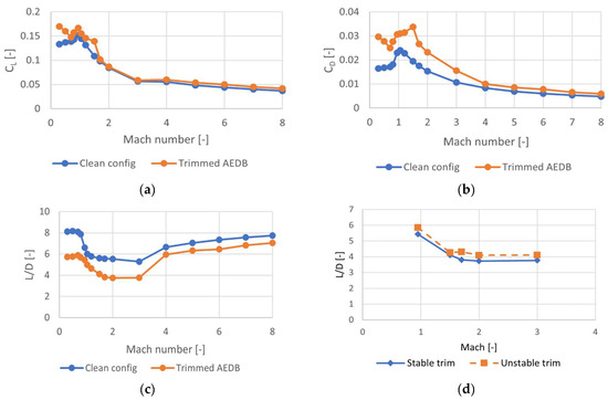
Figure 17.
Comparison between clean and trimmed configuration for C_L (a), C_D (b), and L/D (c). Comparison between stable and unstable configurations in terms of L/D (d).
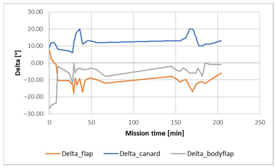
Figure 18.
Summary of surface deflections throughout the entire reference trajectory.
As a result of the introduction of control surfaces on the reference mission (Section 3), the updated profile can be introduced (Figure 19a), together with the propellant mass variation over time, as shown in Figure 19b, which takes into account the selected fuel depletion sequence [19]. The Brussels-to-Sydney mission can be completed with a total travel time of 3 h 24 min. The time required to perform the subsonic climb and cruise phases is equal to 26 min, while the time required to perform the supersonic and hypersonic climb is equal to 29 min. A total time of 55 min is needed to reach the beginning of cruise conditions, while the cruise phase lasts 1 h 29 min. The highest propellant consumption rate is experienced at the beginning of the mission, while the vehicle performs the climb phases [22]. During cruise the propellant mass consumption is instead reduced. A total of 179 tons of propellant mass are needed to complete the mission, while about 2 tons are left at the end. The Lift-to-Drag ratio profile is also reported in Figure 19c. Moreover, Figure 19d reports the Angle of Attack (AoA) selected during the mission. It is interesting to note that values of AoA slightly lower than zero are needed throughout the entire mission. This is because the reference longitudinal body axis is parallel to the upper side of the vehicle for the MR3, meaning that the windward side of the wing is at a positive angle with reference to the flow even when the vehicle AoA is equal to zero. If the AoA is different from zero, the vehicle flies in non-optimal conditions from the point of view of the aerodynamic and propulsive performance. However, the use of low AoAs is required to avoid that the vehicle generates too much lift due to its large lifting surface, which would result in a fast gain/loss of altitude and an increase in the Rate of Climb/Descend.
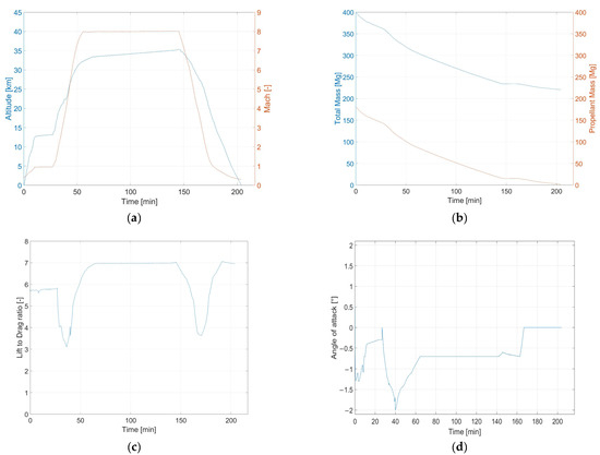
Figure 19.
Updated mission profile trends in trim conditions as a function of time: (a) altitude (blue) and Mach number (orange), (b) vehicle mass (blue) and propellant mass (orange), (c) L/D, and (d) AoA.
4.5. Step 4: Evaluation of Hinge Moment
The derivation of the updated reference trajectory is crucial to identify the most critical sizing points for the actuation of the control surfaces, in terms of hinge moment to be counteracted. Specifically, if the flight condition under investigation is characterized by a Mach number lower than 2, traditional approaches can be exploited [12]. In this case the hinge moment is evaluated as a function of the hinge moment coefficient, which in turn depends on the aircraft AoA and the maximum deflection foreseen in that specific condition. Therefore, up to Mach 2, considering the mission profile and given the coefficients , , , the deflection δ of the mobile surface, and the angle of attack, α, the hinge moment is obtained as in Equation (5).
where is the air density in , V is the airspeed , S is the mobile surface area , c is the mobile surface chord [m], and
Conversely, for Mach numbers higher than 2, the theory illustrated above is not applicable. An algorithm based on the oblique-shock theory is here suggested to overcome this limitation. This approach has been applied for the first time by Àlex Navó and Josep M. Bergada [29] in the Aerodynamic Study of NASA’s X-43A Hypersonic Aircraft, where a 2D aerodynamic study of NASA’s X-43A Hypersonic Aircraft is developed using two different approaches. The first approach is analytical and based on the resolution of the oblique shock wave and Prandtl–Meyer expansion wave theories, supported by an in-house program and considering a simplified aircraft layout. The second approach involves the use of a Computational Fluid Dynamics (CFD) package, OpenFOAM, and the real shape of the aircraft. Then, some CFD results have been validated against experimental data. The published results suggest the possibility to exploit the oblique-shock theory as an effective and reliable model for conceptual design. To determine the hinge moment of the control surface exposed to a supersonic flow, it is necessary to study the oblique shock wave formation from the aircraft’s leading edge up to the area of the movable surface itself. Figure 20 shows an idealized flight vehicle with a deflected control surface, as also suggested in [27], to graphically represent the model.
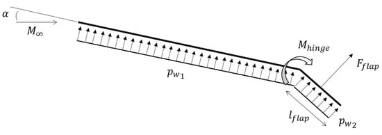
Figure 20.
Ideal vehicle representation.
Using the picture as reference (downwards deflection), it is assumed that a constant pressure acts on the lower side of the vehicle, whereas a constant acts on the lower side of the deflected control surface (this is the ideal inviscid case), which has the dimensions (length) and (width) . The flap force is then computed as in Equation (7).
The flap force times its lever arm with respect to the flap axis must be balanced by the hinge moment, as reported in Equation (8).
The theory of an oblique shock wave is used to determine the pressure value acting on the lower side of the vehicle. For complex hypersonic configurations, such as the one reported in Figure 21, the external flow can face multiple shocks before reaching the leading edge of the control surface.

Figure 21.
Schematical representation of oblique shock formations along a waverider configuration.
Through the θ-β-Mach relationship reported in Equation (9), it is possible to find out the shock angle β produced by the θ deflection at that Mach number.
Once the oblique shock wave angle is defined, it is possible to estimate the characteristics of the flow after the oblique shock. Knowing the characteristics of the flow in front of the oblique shock, in particular the Mach number, and the static pressure, , it is possible to estimate the static pressure, , and the Mach number, , behind the shock as in Equations (10) and (11).
Then, it is possible to evaluate the pressure acting on the deflected control surface. Through the θ-β-Mach relationship, it is possible to find out the shock angle produced by the deflection of the control surface at Mach number evaluated in the first step. The pressure of the flow after the second oblique shock wave is determined as in Equation (12).
Once the values of the hinge moments are known, the required power can be estimated as in Equation (13), assuming the hydraulic analogy for actuation devices.
where is the hinge moment previously determined in [Nm], ω is the angular speed of the surface [rad/s] and η is the efficiency of the transmission.
4.6. Step 5: Detailed Estimation of Power Demand
As a result of the application of the twofold algorithm for hinge moment estimation, power demand per each control surface has been obtained as shown in Figure 22, together with the overall FCS power demand. Since the work does not investigate the lateral plane, the impact of rudder deflections (Table 3) has been introduced considering a maximum deflection at low speed and progressively reducing its authority while moving towards a higher flight regime (a trim reference condition has not been imposed). In this case, the hinge moment has been evaluated similarly to other surfaces, considering multiple shocks on the vehicle’s nose and leeward side, as well as on vertical stabilizers. To summarize, it clearly emerges that the most critical phases, from the point of view of the required power, are those at take-off, low supersonic acceleration, and approach, where peaks of over 130 kW are reached, while an average 20 kW is sufficient to support deflections in hypersonic cruise. From an operational point of view, the surface that requires the highest power level is the body flap, with a peak of about 45 kW. The rudders’ contribution appears negligible, showing that longitudinal-plane-related deflections may be more relevant, even if the simplified approach used for rudder actuation assessment shall be further verified.
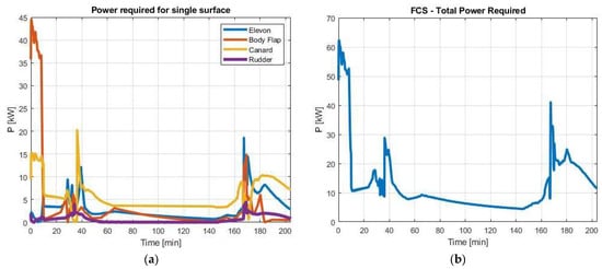
Figure 22.
Power demand per each control surface and final FCS power budget.
It is therefore important to notice that, in this case, the practice of considering cruise conditions as reference sizing point would have caused a non-negligible error.
According to what is illustrated in the methodology section, peak values can be directly associated to actuation mass, as reported in Table 4. Reference values for mass (kg) per unit power (kW) are derived from [30], as far as electro-hydrostatic actuators are concerned. Better performance can also be expected considering technological improvement and far-term Entry-Into-Service (EIS) of the vehicle. At the actual state of the art, the overall mass of actuators is estimated to be around 852 kg.

Table 4.
Actuators mass.
5. Conclusions and Future Works
This paper describes a methodology to anticipate the Flight Control System design for high-speed vehicles at the conceptual design stage, properly considering the interactions at vehicle level and allowing for the prediction of the behavior of the system throughout the entire mission. This work, which focuses mainly on the longitudinal plane of the vehicle, is considered an initial step towards complete FCS design, usually faced through multiple iterations. The integrated systems design methodology discussed in this paper starts with a preliminary mission analysis of the reference vehicle, once its main characteristics are known for the clean configuration (no control surfaces). Then, according to stability analyses, new control surfaces can be introduced and analyzed to predict their effectiveness on the trim, together with contribution to the vehicle lift and drag coefficients. At this stage, interaction with the propellant system is fundamental to identify the minimum surface deflections required to guarantee the aircraft trim (reducing trim drag). Indeed, in order to minimize the exploitation of control surfaces, thus limiting the detrimental effects on the aerodynamic efficiency, propellant tanks can be properly shaped and integrated on board, and ad hoc depletion sequences can be adopted to match the desired Center of Gravity (CoG) shift throughout the mission. Maximum required control surface deflections are used as inputs for the estimation of hinge moments to be counteracted by the actuation system. A novel approach is here suggested to extend the formulation available in the Literature for hinge moment estimation, beyond the transonic regime. Ultimately, the FCS design is completed with the estimation of power requirements for the on-board system. The exploitation of the methodology for the design and sizing of the FCS is applied to the STRATOFLY MR3 case study, a Mach 8 waverider concept for civil antipodal flights. The work is aimed at warning designers not to neglect the trim drag effect during the conceptual design of the vehicle, since this may risk jeopardizing the mission concept. A methodology to approach the FCS characterization is proposed both in terms of trim map generation as well as of on-board actuation system definition. Additionally, the work demonstrates that cruise conditions are not meaningful to predict peak power requirements for FCS feeding, suggesting that the integrated design approach is the only way to guarantee adequate result consistency for high-speed vehicles. Future works will deal with both a further refinement of the sizing approach for control surfaces, extending the model to include lateral plane analyses, and an additional verification of the hinge moment algorithm. The integration of this initial step for FCS design within a broader system characterization is expected. Additionally, the application of the process presented in this paper to different case studies is envisaged.
Author Contributions
Conceptualization, D.F., R.F. and N.V.; Methodology, D.F., R.F. and N.V.; Software, O.G.; Formal analysis, O.G.; Investigation, O.G.; Data curation, D.F. and O.G.; Writing—original draft, D.F., O.G. and R.F.; Writing—Review and Editing, D.F. and R.F.; Visualization, D.F. and R.F.; Supervision, D.F. and N.V.; Project administration, N.V.; Funding acquisition, N.V. All authors have read and agreed to the published version of the manuscript.
Funding
This work has been carried out within the frame of the “STRATOspheric FLYing opportunities for high-speed propulsion concepts” (STRATOFLY) project. This project has received funding from the European Union’s Horizon 2020 research and innovation program under grant agreement No. 769246. The authors also would like to thank Luca De Giorgi for the valuable support provided during the post-graduate scholarship.
Data Availability Statement
The data associated to this work are not publicly available outside Project Consortium.
Conflicts of Interest
The authors declare no conflict of interest.
Nomenclature
| AoA | Angle of Attack |
| ATR | Air Turbo Rocket |
| CoG | Center of Gravity |
| DMR | Dual Mode Ramjet |
| EIS | Entry Into Service |
| FCS | Flight Control System |
| L/D | Lift-to-Drag ratio |
| MTOM | Maximum Take-Off Mass |
| selected mobile surface length [m] | |
| static pressure [Pa] | |
| static pressure on selected mobile surface [Pa] | |
| selected mobile surface width [m] | |
| drag coefficient | |
| lift coefficient | |
| hinge moment coefficient | |
| hinge moment coefficient at angle of attack equal to zero | |
| pitching moment coefficient for angle of attack equal to zero | |
| global pitching moment coefficient | |
| contribution to pitching moment coefficient due to elevons | |
| contribution to pitching moment coefficient due to canard | |
| contribution to pitching moment coefficient due to body flap | |
| contribution to pitching moment coefficient due to thrust | |
| global pitching moment coefficient for clean aircraft configuration only | |
| contribution to pitching moment coefficient due to angle of attack | |
| force acting on the selected mobile surface [N] | |
| moment generated by the actuator [Nm] | |
| hinge moment [Nm] | |
| Mach number | |
| P | power demand to the actuator [W] |
| angle of attack | |
| oblique shock wave angle | |
| ratio of specific heats of air | |
| deflection angle of the control surface | |
| efficiency of the transmission | |
| wedge angle of the lower part of the vehicle | |
| angular speed of the control surface [rad/s] | |
| variation of drag coefficient due to control surfaces | |
| variation of lift coefficient due to control surfaces | |
| global variation of pitching moment coefficient | |
| i-th effect of control surfaces on global pitching moment coefficient | |
| effect of thrust vector on global pitching moment coefficient |
References
- Andro, J.-Y.; Rotärmel, W.; Nebula, F.; Morani, G.; Steelant, J. Design of the Actuation System for the Hexafly-Int Hypersonic Glider. In Proceedings of the 1st International Conference on High-Speed Vehicle Science and Technology, Moscow, Russia, 26–29 November 2018. [Google Scholar]
- Viola, N.; Fusaro, R.; Gori, O.; Marini, M.; Roncioni, P.; Saccone, G.; Saracoglu, B.; Ispir, A.C.; Fureby, C.; Nilson, T.; et al. STRATOFLY MR3—How to reduce the environmental impact of high-speed transportation. In Proceedings of the AIAA Scitech 2021 Forum, Online, 11–15 and 19–21 January 2021. [Google Scholar] [CrossRef]
- Rufolo, G.C.; Roncioni, P.; Marini, M.; Votta, R.; Palazzo, S. Experimental and numerical aerodynamic data integration and aerodatabase development for the PRORA-USV-FTB_1 reusable vehicle. In Proceedings of the 14th AIAA/AHI International Space Planes and Hypersonic Systems and Technologies Conference, Canberra, Australia, 6–9 November 2006; pp. 1173–1212. [Google Scholar] [CrossRef]
- Viola, N.; Roncioni, P.; Gori, O.; Fusaro, R. Aerodynamic characterization of hypersonic transportation systems and its impact on mission analysis. Energies 2021, 14, 3580. [Google Scholar] [CrossRef]
- Fusaro, R.; Viola, N.; Ferretto, D.; Vercella, V.; Fernandez Villace, V.; Steelant, J. Life cycle cost estimation for high-speed transportation systems. CEAS Space J. 2020, 12, 213–233. [Google Scholar] [CrossRef]
- Rajaram, D.; Cai, Y.; Chakraborty, I.; Mavris, D.N. Integrated sizing and optimization of aircraft and subsystem architectures in early design. J. Aircr. 2018, 55, 1942–1954. [Google Scholar] [CrossRef]
- Javaid, K.H.; Serghides, V.C. Thrust-matching requirements for the conceptual design of hypersonic waverider vehicles. J. Aircr. 2005, 42, 1055–1064. [Google Scholar] [CrossRef]
- Ingenito, A. Design of Supersonic/Hypersonic Vehicles. In Subsonic Combustion Ramjet Design; Springer Briefs in Applied Science and Technology; Springer: Cham, Switzerland, 2021. [Google Scholar] [CrossRef]
- Ferretto, D.; Fusaro, R.; Viola, N. A conceptual design tool to support high-speed vehicle design. In Proceedings of the AIAA Aviation 2020 Forum, Online, 15–19 June 2020. [Google Scholar] [CrossRef]
- Bowcutt, K.G. Physics drivers of hypersonic vehicle design. In Proceedings of the 22nd AIAA International Space Planes and Hypersonics Systems and Technologies Conference, Orlando, FL, USA, 17–19 September 2018. [Google Scholar] [CrossRef]
- Ingenito, A.; Gulli, S.; Bruno, C.; Colemann, G.; Chudoba, B.; Czysz, P.A. Sizing of a fully integrated hypersonic commercial airliner. J. Aircr. 2011, 48, 2161–2164. [Google Scholar] [CrossRef]
- Roskam, J. Airplane Design; DARcorporation: Lawrence, KS, USA, 1985. [Google Scholar]
- Torenbeek, E. Synthesis of Subsonic Airplane Design: An Introduction to the Preliminary Design of Subsonic General Aviation and Transport Aircraft, with Emphasis on Layout, Aerodynamic Design, Propulsion and Performance; Springer Science & Business Media: Dordrecht, The Netherlands, 2013. [Google Scholar]
- Raymer, D. Aircraft Design: A Conceptual Approach; American Institute of Aeronautics and Astronautics: Reston, VA, USA, 2012. [Google Scholar]
- Sadraey, M.H. Aircraft Design: A Systems Engineering Approach; John Wiley & Sons: Hoboken, NJ, USA, 2012. [Google Scholar]
- Sitchin, E.V.; Smith, B.; Stahlschmidt, W.W.; Raz, A.K.; Delaurentis, D.A. Modeling Hypersonic Vehicle Interdependencies at the Subsystem Level. In Proceedings of the AIAA 2021 Aviation Forum, Virtual, 2–6 August 2021. [Google Scholar] [CrossRef]
- Scigliano, R.; Pezzella, G.; Marini, M.; Di Benedetto, S.; Steelant, J. Aerothermal design of the Hexafly-INT glider. In Proceedings of the 2016 AIAA Space and Astronautics Forum, Long Beach, CA, USA, 13–16 September 2016. [Google Scholar] [CrossRef]
- Scigliano, R.; Benedetto, S.D.; Marini, M.; Villace, V.; Steelant, J. Hexafly-INT hypersonic vehicle thermal protection system design. In Proceedings of the 71st International Astronautical Conference, Online, 12–14 October 2020. [Google Scholar]
- Ferretto, D.; Fusaro, R.; Viola, N. Propellant subsystem design for hypersonic cruiser exploiting liquid hydrogen. In Proceedings of the AIAA 2022 Aviation Forum, Chicago, IL, USA, 27 June–1 July 2022. [Google Scholar] [CrossRef]
- Steelant, J.; van Duijn, M. Structural analysis of the LAPCAT-MR2 waverider based vehicle. In Proceedings of the 17th AIAA International Space Planes and Hypersonic Systems and Technologies Conference, San Francisco, CA, USA, 11–14 April 2011. [Google Scholar] [CrossRef]
- Rodriguez-Segade, M.; Hernandez, S.; Diaz, J. Multi-bubble scheme and structural analysis of a hypersonic stratospheric flight vehicle. Aerosp. Sci. Technol. 2022, 124, 107514. [Google Scholar] [CrossRef]
- Ispir, A.C.; Goncalvers, P.M.; Saracoglu, B.H. Analysis of a combined cycle propulsion system for STRATOFLY hypersonic vehicle over and extended trajectory. In Proceedings of the 9th EASN International Conference on “Innovation in Aviation & Space”; MATEC Web of Conferences, Athens, Greece, 3–6 September 2019; EDP Sciences: Les Ulis, France, 2019; Volume 304. [Google Scholar] [CrossRef]
- Seebass, R. Sonic boom theory. J. Aircr. 1969, 6, 177–184. [Google Scholar] [CrossRef]
- Ispir, A.C.; Saracoglu, B.H. Development of a 1D dual mode ramjet model for a hypersonic civil aircraft. In Proceedings of the AIAA Propulsion and Energy 2019 Forum, Indianapolis, IN, USA, 19–22 August 2019. [Google Scholar] [CrossRef]
- Steelant, J.; Varvill, R.; Defoort, S.; Hanneman, K.; Marini, M. Achievements obtained for sustained hypersonic flight within the LAPCAT-II Project. In Proceedings of the 20th International Space Planes and Hypersonic Systems and Technologies Conference, Glasgow, UK, 6–9 July 2015. [Google Scholar] [CrossRef]
- Langener, T.; Erb, S.; Steelant, J. Trajectory simulation and optimization of the LAPCAT-MR2 hypersonic cruiser concept. In Proceedings of the 29th Congress of the International Council of the Aeronautical Sciences, St. Petersburg, Russia, 7–12 September 2014. [Google Scholar]
- Hirschel, E.H.; Weiland, C. Selected Aerothermodynamic Design Problems of Hypersonic Flight Vehicles; Springer Science & Business Media: Berlin/Heidelberg, Germany, 2009; Volume 229. [Google Scholar]
- Koelle, D.E.; Kuczera, H. Sanger II, an advanced launcher system for Europe. Acta Astronaut. 1989, 19, 63–72. [Google Scholar] [CrossRef]
- Navò, A.; Bergada, J.M. Aerodynamic study of the NASA’s X-43A hypersonic aircraft. Appl. Sci. 2020, 10, 8211. [Google Scholar] [CrossRef]
- Chakraborty, I.; Mavris, D.N.; Emeneth, M.; Schneegans, A. A system and mission level analysis of electrically actuated flight control surfaces using Pacelab SysArc. In Proceedings of the 52nd Aerospace Sciences Meeting, National Harbor, MD, USA, 13–17 January 2014. [Google Scholar] [CrossRef]
Disclaimer/Publisher’s Note: The statements, opinions and data contained in all publications are solely those of the individual author(s) and contributor(s) and not of MDPI and/or the editor(s). MDPI and/or the editor(s) disclaim responsibility for any injury to people or property resulting from any ideas, methods, instructions or products referred to in the content. |
© 2023 by the authors. Licensee MDPI, Basel, Switzerland. This article is an open access article distributed under the terms and conditions of the Creative Commons Attribution (CC BY) license (https://creativecommons.org/licenses/by/4.0/).