1. Introduction
The rotor vortical wake is among the most complex fluid dynamic structures in the helicopter unsteady flow field and strongly affects the flight performances of the helicopter. For instance, the shed blade tip vortices in the rotor wake may intersect with the following rotor blade causing the blade–vortex interaction (BVI) phenomenon, which significantly affects the blade airloads and results in the obtrusive noise levels. The rotor-induced wake that interacts with the surrounding obstacles can typically degrade the helicopter performance and creates a hazardous environment. The interference of the main/tail rotor/fuselage negatively influences the aerodynamics of the vehicle. For these reasons, accurate modeling of the rotor vortical flow is essential for helicopter rotor aerodynamics and aeroacoustics prediction.
Over the last three decades, Computational Fluid Dynamics (CFD) simulations have gained popularity due to their capability of resolving most phenomena of interest. However, an inherent issue of these simulations is that the vortex features are prematurely deformed and dissipated due to the dissipative nature of numerical schemes, this makes the employment of such techniques in helicopter rotor flows unsatisfactory. In recent years, four major classes of numerical methods, including scale-resolving simulation (SRS) [
1,
2,
3], high-order spatial discretization schemes [
4,
5,
6,
7], vorticity confinement (VC) method [
8,
9,
10,
11], and grid refinement techniques [
12,
13,
14] have emerged to help improve the capability of preserving vortices in CFD simulations. Nevertheless, some of them are often prohibitive for industrial applications due to the substantial computational time and resources. For example, the SRS approaches are capable of providing a more detailed description of vortices but require a large grid system to exploit the full potential of this technique. Even if the high-order schemes are able to alleviate the over-dissipation of the vortical structure with appropriate grid densities, the computation of high-order derivatives or the construction of complex stencils may result in additional computational costs. In terms of grid refinement techniques, Automatic Mesh Refinement (AMR), the most representative method for grid refinement, is also computationally expensive because of the additional mesh points created in the refined region. In contrast, the VC method presents potential advantages in the computational efficiency of preserving vortices as the grid system could be maintained at a moderate level. As a result, increasing numbers of research have focused on such an approach.
Vorticity confinement is a concept that allows preventing a vortex from being inorderly diffused by adding an ad hoc anti-diffusion term into the standard Euler/Navier–Stokes equations. It has proved effective in simulating vortex-dominated flows, especially for cases without satisfactory mesh sizes. Currently, two formulations of the VC method have been developed and briefly referred to as VC1 [
15] and VC2 [
16].
In the first vorticity confinement (VC1) scheme, the VC term is derived from the first derivative of velocity. It transports vorticity in the direction of increasing vorticity magnitude gradient, counteracting the spreading effect due to the numerical dissipation. Over the past decades, the VC1 formulation became attractive in the simulation of vortex-dominated flows due to its algorithmical simplicity and efficiency, especially for helicopter rotor flows. For instance, Steinhoff et al. [
17] first applied the VC1 to hovering HELIX I rotor flows and received a promising result. Biava and Vigevano [
8] investigated the variation of confinement parameters on thrust coefficient for ONERA 7A four-bladed rotor flows in both hover and forward flight. Even though the VC1 scheme is widely adopted, it suffers from two disadvantages. The first is related to a difficulty in the theoretical analysis of its properties, the singularity of VC1 term at the vortex center. The second concerns the conservation of the governing equations while using the VC1 term.
In order to correct the drawback of the VC1 scheme, the second vorticity confinement (VC2) formulation was later introduced [
16]. The VC2 formulation is derived from the second derivative of velocity with no singularity at the vortex core, which allows more detailed analytical investigations on its properties [
18,
19] and with an exact conservative expression, which makes it easy to extend to higher-order schemes [
20,
21,
22]. In recent years, the capabilities of VC2 formulation and its higher-order schemes on vorticity preservation and computational efficiency have been demonstrated by some studies [
9,
10,
23] carried out in helicopter rotor flows.
Initially, the VC1 method was developed for incompressible flows. After several attempts [
24,
25], Hu et al. [
26] presented a more stable VC correction for compressible simulations by interpreting Steinhoff’s VC1 formulation as a body force source term and adding to both the momentum and energy equations. However, additional studies [
18,
27] found that far better results could be obtained when the VC term was removed from the energy conservation equation. For this reason, Costes [
18] suggested that the contributions of the VC term would only be treated as purely numerical corrections to the momentum conservation equation rather than physical source terms. On this basis, the compressible VC1 and VC2 schemes were successfully applied to a wide range of cases.
Besides the compressible extensions of the VC schemes, another primary challenge is the determination of the confinement parameter
, which controls the magnitude of the negative diffusion in the vorticity confinement, since a mistake in the choice of
would result in the non-physical solutions and affect the stability of numerical simulation. To maintain dimensional consistency with the momentum terms, three scaled confinement parameters were derived by Lohner et al. [
28] through dimensional analysis to ensure that they had the dimensions of velocity. Robinson [
29] proposed a scaling expression based on helicity by extending Lohner’s work. Butsuntorn and Jameson [
30] further extended the helicity formulation of Robinson by including a non-dimensional scaling parameter based on the local mesh size. In most studies, the
value comes from a trial-and-error procedure, which is less efficient. Several attempts have been put forward to remove the empiricism of confinement parameter selection. Costes and Kowani [
18,
31] derived a dynamic confinement parameter related to the local vorticity. Hahn and Iaccarino [
32] introduced a new adaptive VC parameter related to the difference between central and upwind discretization of the convection terms. More recently, Povitsky A et al. [
33] employed the TVD (Total Variation Diminishing) limiters to reduce the sensitivity of confinement parameter values. Nonetheless, this problem is still not completely solved due to the non-conservation of the VC2 scheme introduced by the
value varying in space.
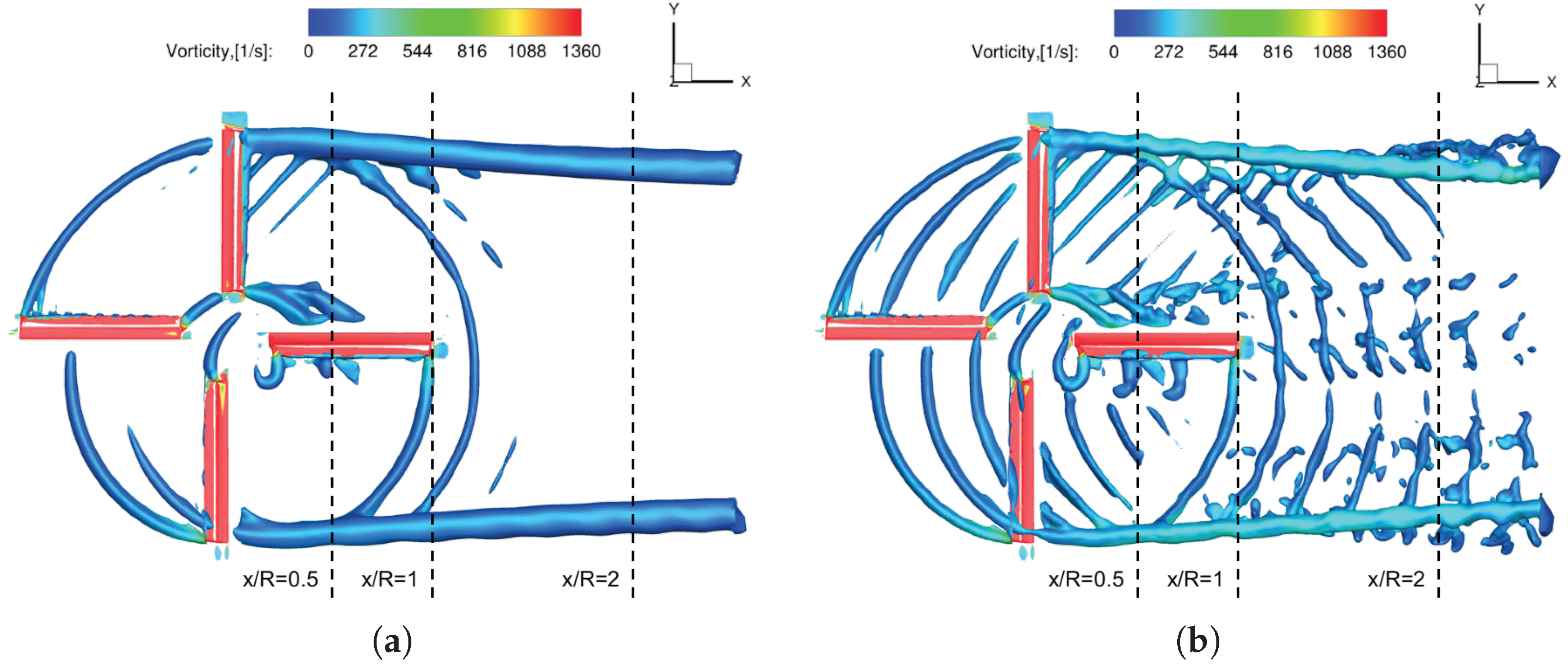
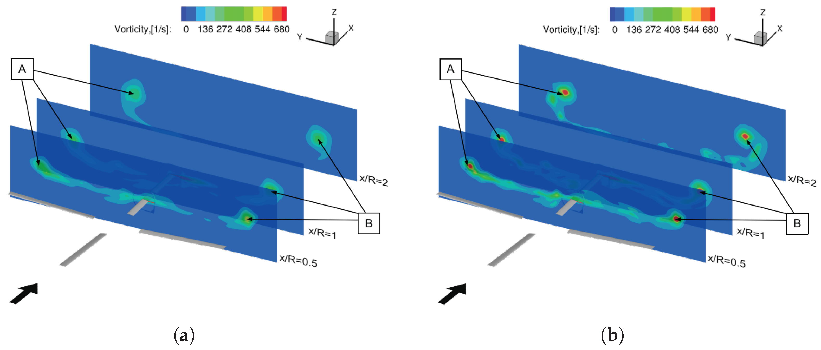
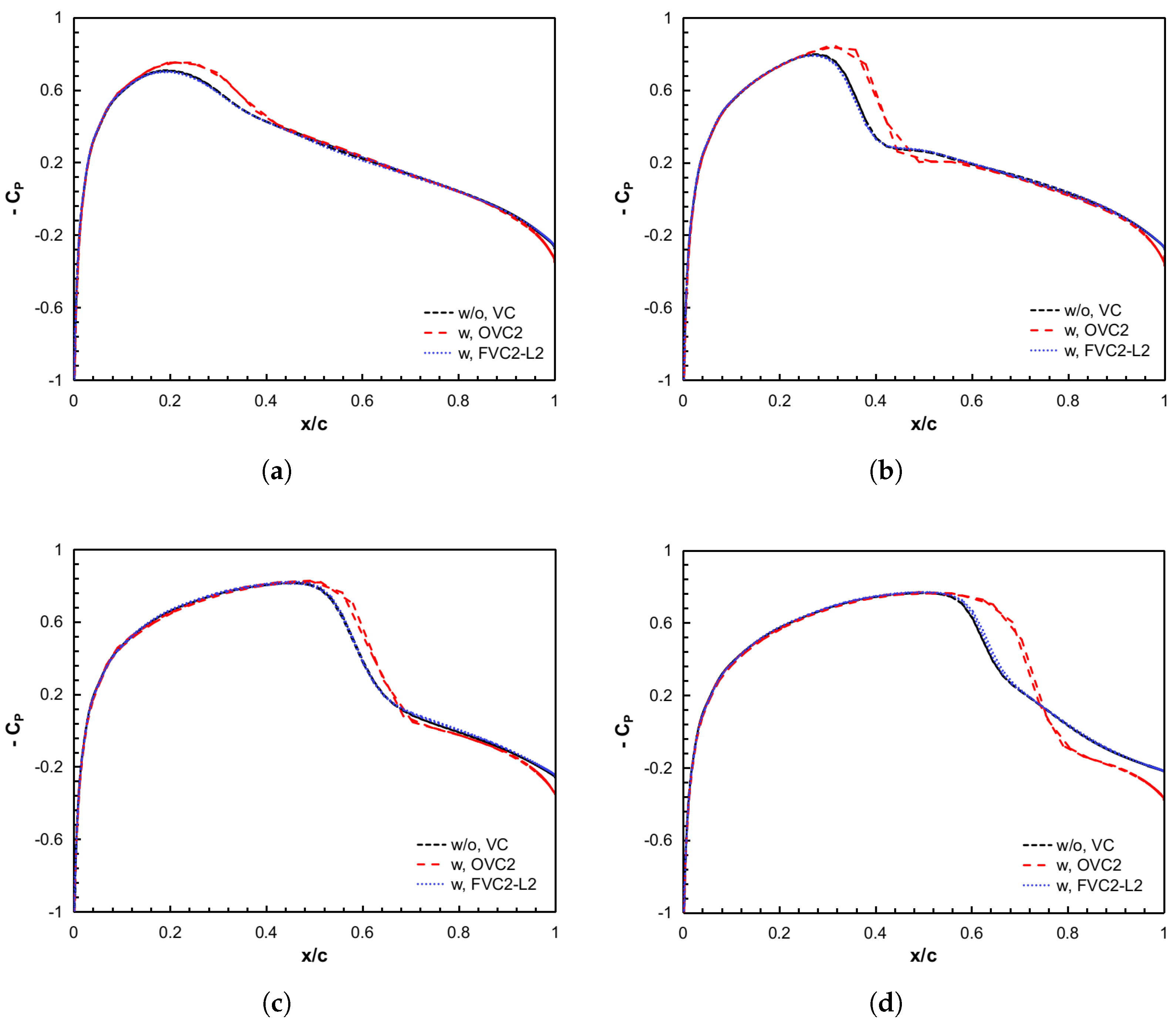
In spite of the number of research employing VC to balance the excessive diffusion of vortical flows, there still remains a fundamental problem. In the standard VC method, the non-zero vorticity magnitude is adopted for detecting vortex features by default. However, it is not appropriate to use vorticity magnitude for vortex detection, particularly at the boundary and shear layer regions where there is no vortex but the vorticity magnitude is not equal to zero. It will cause over-confinement and spurious vortical structures in the results. To eliminate this issue, some studies [
10,
34,
35] combined the standard VC method with the advanced vortex feature detection techniques, resulting in the vortex feature-based VC (FVC1 or FVC2) approach. In our previous work [
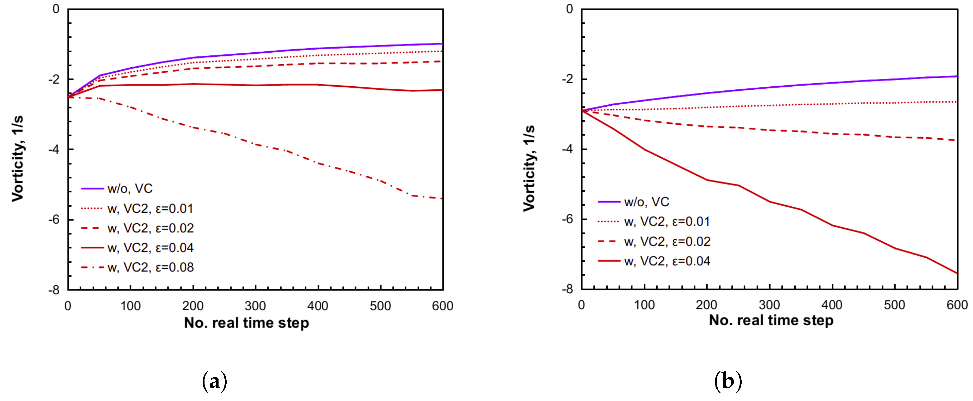
11], the benefits of such treatment for 3D vortex-dominated flows in terms of computational stability, aerodynamic prediction, vorticity preservation, and computational efficiency, were explicitly demonstrated by comparing the standard VC2 scheme with two FVC2 formulations combining different vortex feature detection techniques (
Q and
). Moreover, the
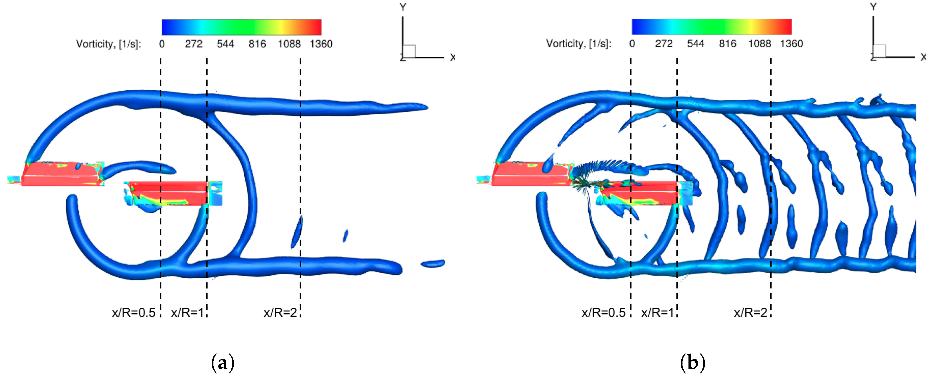
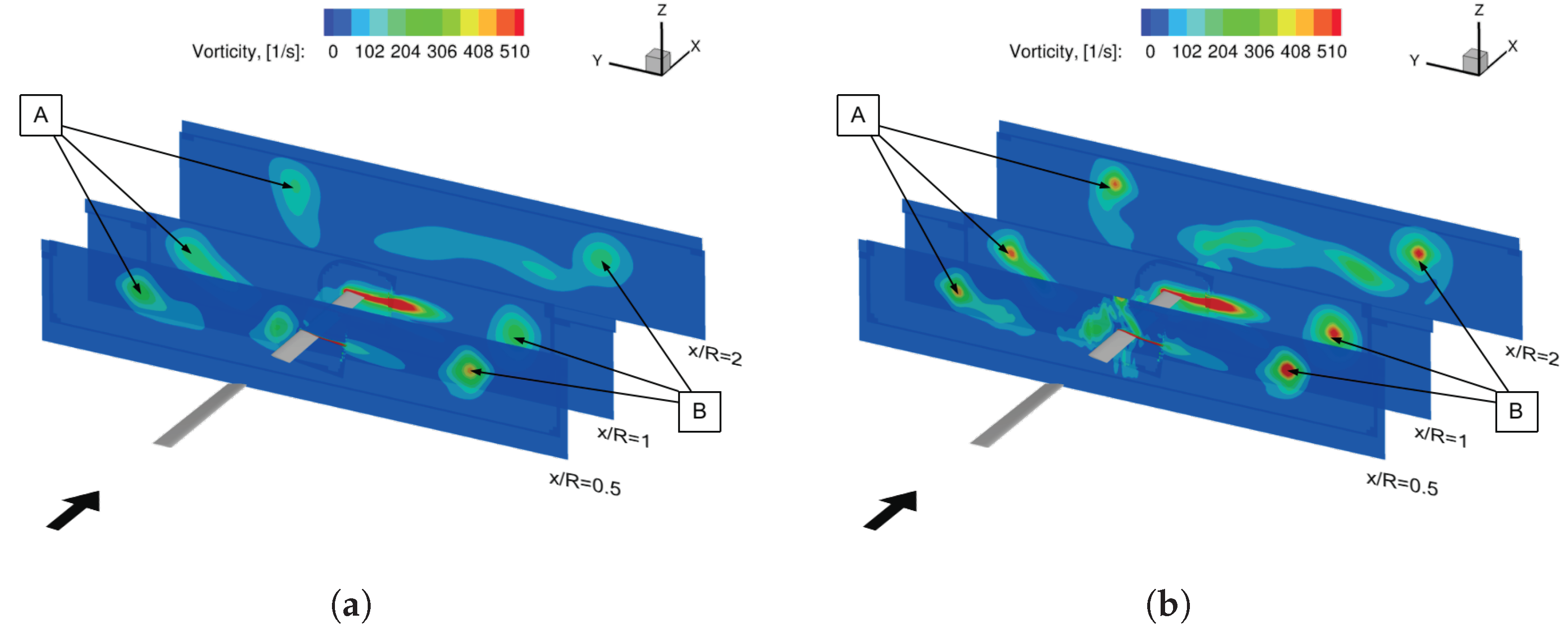
-based VC2 (FVC2-L2) scheme expressed a higher resolution of the vortical structure, more robust computational procedure, more accurate aerodynamic loads, and almost the same computational time cost if compared to the
Q-based VC2 (FVC2-Q) scheme. Nevertheless, the better-performing FVC2-L2 scheme still needs to be further evaluated for helicopter rotor aerodynamic and aeroacoustic predictions, especially for the BVI phenomenon.
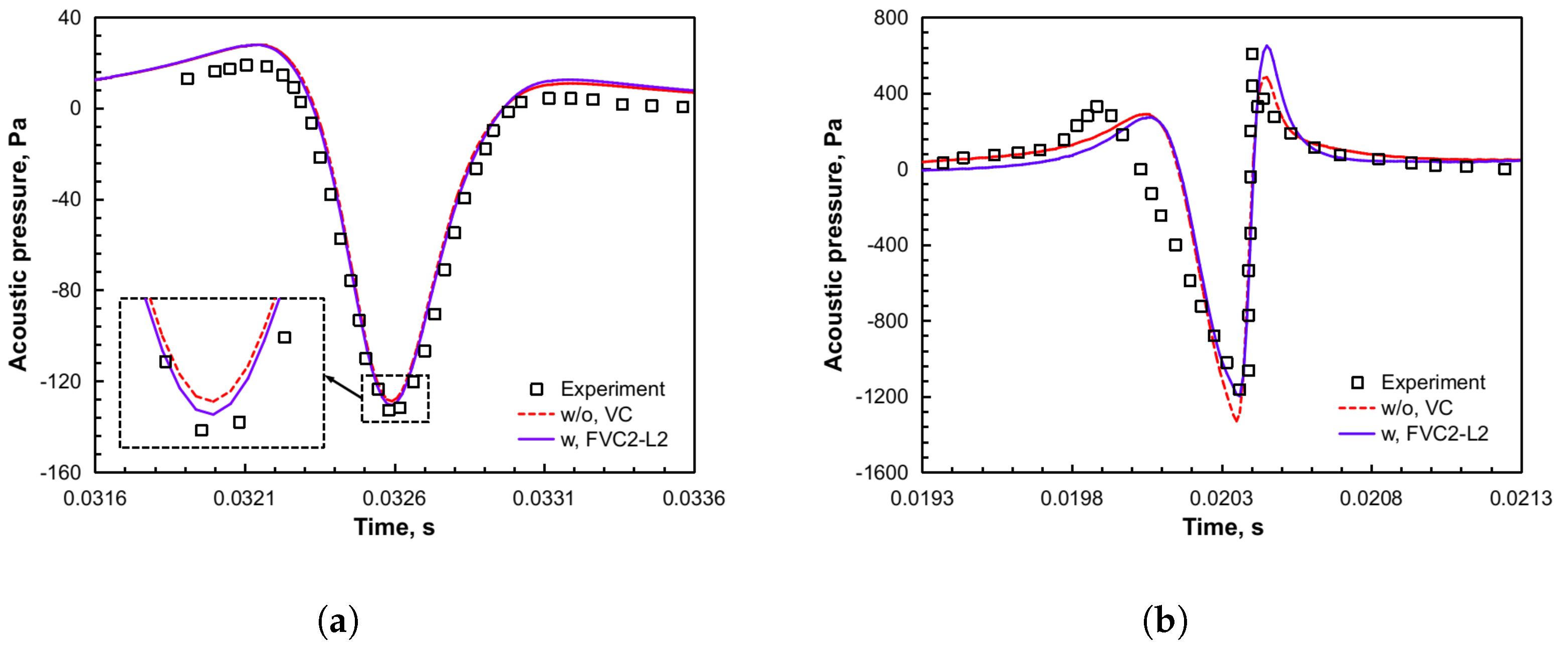
The main objective of this study is to evaluate the capabilities of the FVC2-L2 scheme to predict unsteady airloads, rotor wake development, and rotor noise radiation, particularly under BVI conditions. In addition, it is worth mentioning that the application of the
-based VC2 formulation to the study of helicopter rotor aerodynamics and aeroacoustics constitutes a further original contribution of this paper. Firstly, the HART-II baseline configuration was simulated to resolve the BVI phenomenon by using ROSITA, a multi-block, structured grid CFD solver that implements the FVC2-L2 scheme [
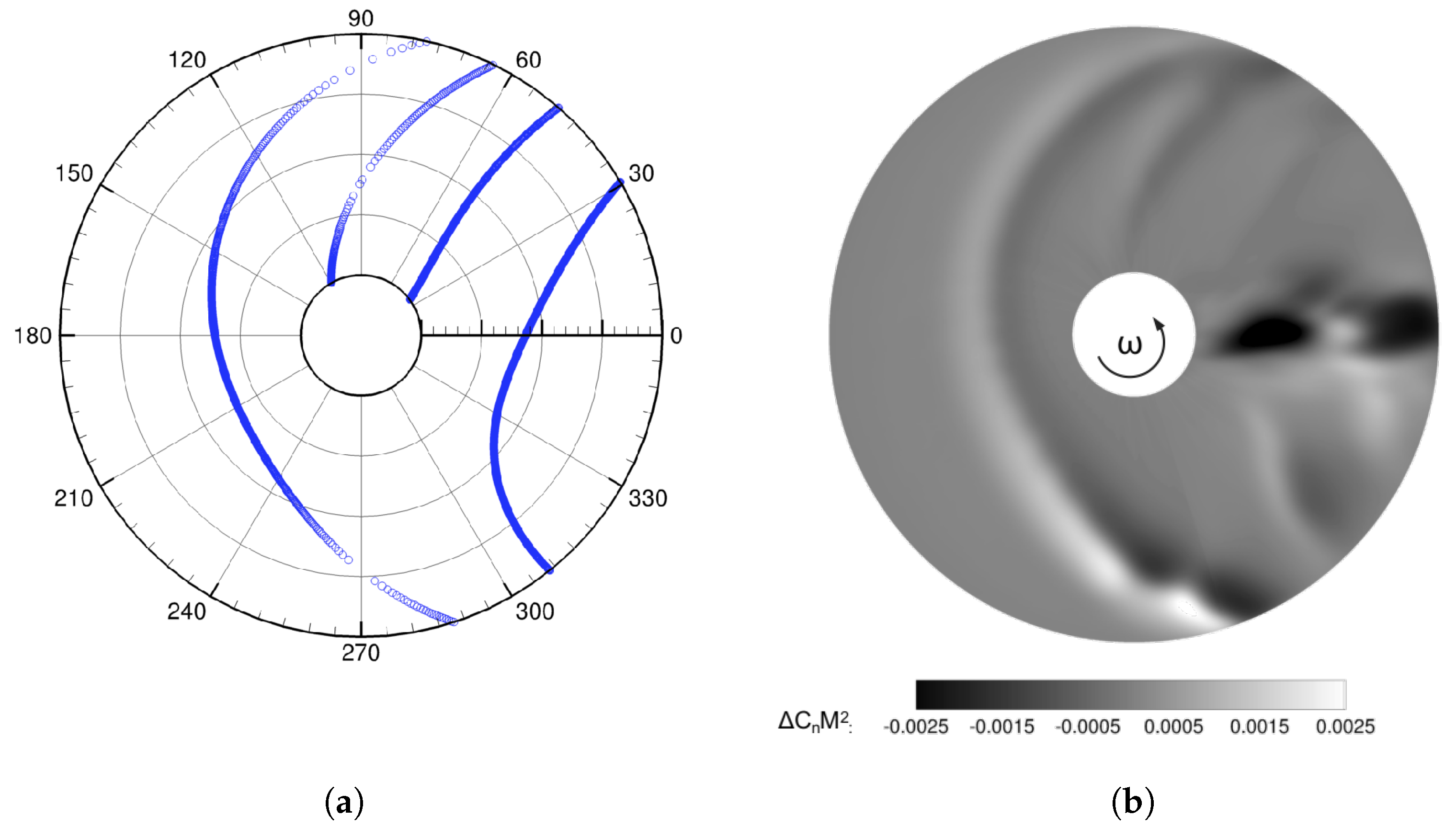
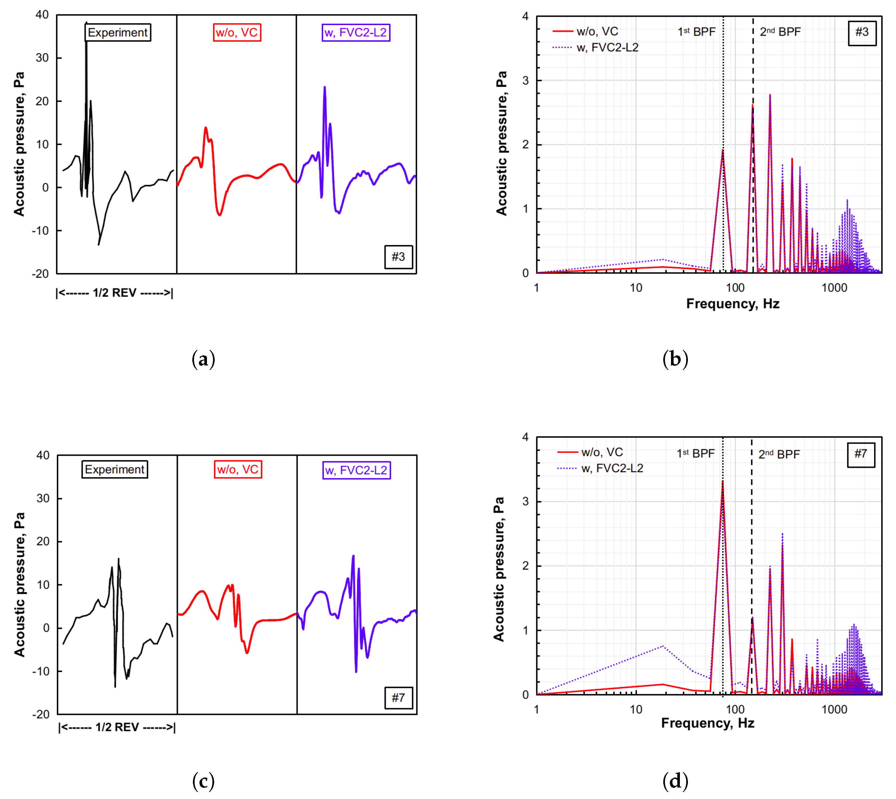
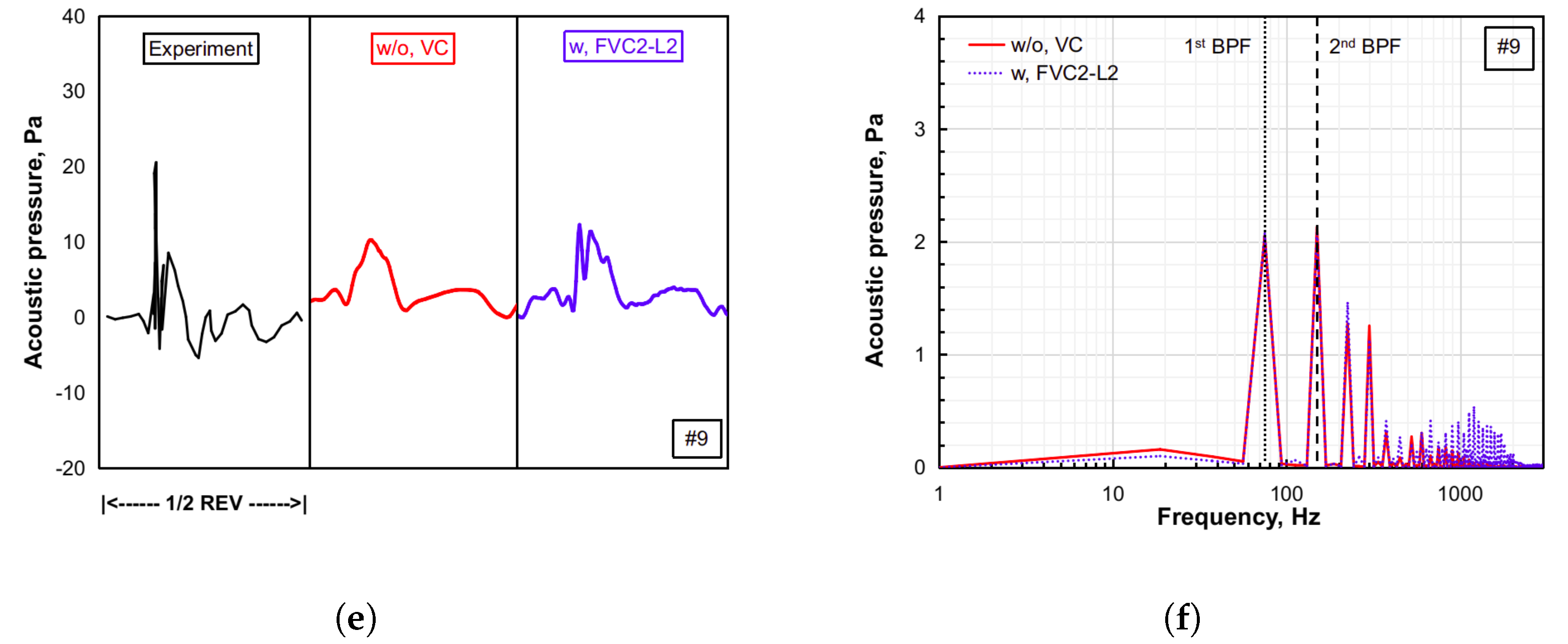
11], and an in-house developed multi-dimensional delta trim procedure. Afterward, together with the permeable surface Ffowcs Williams–Hawkings (PS-FWH) equation, the influence of the FVC2-L2 scheme in rotor noise predictions was assessed via two benchmark test examples.
The remainder of this paper is structured as follows. In
Section 2, the numerical implementations of the CFD approach and the FVC2-L2 scheme are introduced. Moreover, the in-house developed trimming method and aeroacoustic solver are mentioned.
Section 3 discusses the application of the FVC2-L2 scheme in the HART-II rotor baseline configuration and the acoustic analysis of the non-lifting UH-1H hovering rotor and the AH-1/OLS low-speed descending flight rotor with the use of the FVC2-L2 scheme. Finally, the main conclusions are summarized in
Section 4.


