1. Introduction
In the gravity simulation device of a space station, the gravity simulation cabins are connected by several deployable arms. After the launch phase is retracted, the deployable arms are rapidly deployed simultaneously at both sides. Movement creates centrifugal force to simulate gravity. To obtain sufficient centrifugal force, the deployable arm must be long enough, should provide a sufficient rotation radius, and requires a high rotation speed. Therefore, there is a need for a large-scale spatial deployable arm that can be deployed simultaneously at both ends and that is stiff enough to withstand high-speed rotational motion.
Therefore, the deployable mechanism for space applications has gradually become the focus of research [
1]. A lot of work has been executed on mechanism design [
2,
3,
4] and dynamic characteristics [
5,
6,
7]. The focus is on deployable antennae [
8,
9] and spatial multi closed-loop linkage. The thin-walled tubular deployable arm uses the elastic deformation of the thin-walled shell to expand and is also one of the first deployable arms to be studied and applied. In the 1960s, Canada developed the storable tubular extendable member (STEM), which takes advantage of the self-crimping and deployment characteristics of thin alloy strips for deployment [
10,
11]. The double-layer collapsible tubular deployable arm (Bi-STEM) [
12] was developed on the basis of STEM and is composed of two identical overlapping elastic alloy bands that are nested together. The interlocking Bi-STEM has a locking groove on one elastic alloy band and a locking buckle on the other elastic alloy band so that the deployable arms can be interlocked during deployment, improving the bending and torsional stiffness [
13]. The US Air Force Research Laboratory (AFRL) developed the SIMPLE deployable arm [
14,
15]. The deployable arm is driven by the strain energy stored by the bistable tape measure spring and can reach a deployment length of 1 m. Using a bistable carbon fiber STEM, the Space Center of Surrey University in the UK developed a Gossamer deorbit device that can deploy thin film sails [
16]. The collapsible tube mast (CTM) bonds the edges of two STEMs together to form a convex shape on both sides. The German Aerospace Research Institute (DLR) developed a 14-m-long CTM-supported solar sail made of CFRP material [
17,
18]. The National University of Defense Technology completed and successfully launched the “Tiantuo-3” cluster satellite system in 2015 [
19,
20,
21].
The telescopic deployable arm is formed by nesting a series of coaxial circular tubes of different diameters, and the deployment device is generally placed on the axis of symmetry. The deployment device in the sleeve rod is usually a screw system or a rope drive system that can achieve sequential or synchronous deployment. Since the 1980s, various countries have carried out relevant research on telescopic deployable arms, which have been applied to rod antenna extension mechanisms and gravity gradient rods [
22]. Northrob GRUMMAN developed a telescopic deployable arm for the ISIS system. This arm is suitable for applications with relatively large loads [
23,
24]. The China Academy of Space Technology proposed a circulation-driven space sleeve deployable arm. The sleeves at all levels are positioned and locked by a locking mechanism; the drive module includes a crank, a climbing wheel, and a transmission pin, which are the core parts of the new mechanism [
25].
The inflatable deployable arm is deployed when air fills it during inflation and hardens the inflatable membrane. Compared with the mechanical deployable structure, the spatial inflatable deployable structure has the following advantages: it has a small deployment volume, is light weight, is low cost, and has high deployment reliability [
26,
27,
28]. In the 1950s, NASA and other scientific research institutions successively applied space expansion membrane expansion structure technology to satellites such as ECHO I [
29,
30]. The “inflatable gravity gradient rod”, jointly developed by Beijing Institute of Space Mechatronics and Harbin Institute of Technology, was successfully implemented in the new technology experiment-1 satellite and completed the in-orbit inflatable deployment experiment [
31].
There is a hinge connection between the longitudinal rod and the bulkhead of the articulated deployable arm deployment unit. Compared with several of the previous deployable arms, the articulated deployable arm has a higher deployment stiffness and a high repetitive deployment accuracy and is one of the most widely used arms in space applications. The FAST deployable arm developed by ACE-Able is composed of a longitudinal bar, a bulkhead, an elastic cross bar, and a tensioning rope [
32,
33]. ACE-Able has developed another ADAM deployable arm, which uses a rigid rod and a rope to form an overall tensioning structure. The tensioning of the rope is achieved through a special locking mechanism at the crossover point of the rope, which is driven by a sleeve to expand [
34]. DARPA developed the PAFR deployable arm in the 2001 ISAT project [
35,
36]. A motor drives three screws to drive the triangular frame of each level of the deployable arm to gradually expand it. Palmieri [
37,
38] and Hofer [
39,
40,
41] developed a series of deployable soft robot and inflatable robotic arms for aerospace applications.
At present, most spatial deployable arms have one of the following driving modes: motor drive, smart material drive, elastic rod drive, energy storage hinge drive, and inflatable drive. Motor drive is often used for articulated deployable arms. A spiral sleeve or a screw rod converts the rotation of the motor to linear motion, which drives the deployable arm to expand step by step. The structure is relatively complex, and the volume is large, and as the scale of the deployable arm increases, the volume and mass of the driving mechanism also increase. A drive made of a smart material, such as a memory alloy, often drives the deployable arm to expand through the active deformation of the material. The driving method is simple, but the expansion rigidity is poor, and there are high-environment requirements. The elastic rod drive relies on the elastic deformation of the elastic rod to carry out the expansion. The expansion process is unstable, and it is necessary to add an additional speed control mechanism. The energy storage hinge drive relies on the torque provided by the hinge torsion spring. It has a long force transmission path and a large hinge. It is difficult to provide sufficient driving torque for a large-scale deployment mechanism, and the driving efficiency is poor. Pneumatic drive is a driving method for the inflatable deployable arm. Expansion and hardening are achieved by a change in the pressure via inflation. As the size of the deployable arm increases, the required gas volume also gradually increases. The airtightness and environmental requirements of the arm are high. The quality and efficiency of the existing driving methods will be unable to meet the application needs of the ultra-large-space mechanism in the future. Therefore, there is an urgent need for a new high-efficiency, low-mass driving method to meet the needs of large-scale deployable arms in terms of stable expansion and compaction in a small volume.
Since the space gravity simulator requires a large enough rotation radius to generate a centrifugal force, the axial length of the deployable arm must be no less than 50 m, the deployment speed must be fast, and the design must be lightweight. The above-mentioned development drive modes cannot meet the design requirements in terms of development efficiency, development speed, and weight. So, a new development drive mode must be identified.
The driving method of dragging the engine is one of the research topics of interest in recent years. It has the advantages of a short force transmission path and high driving efficiency, is not limited by the scale, and is suitable for the rapid deployment of large-scale deployable arms. In recent years, with the development and application of micro-engines, engines can be dragged and deployed.
With the development of the aerospace industry, the requirements for space deployable arms in space missions are increasing. Currently, the space deployable arms used in orbit have the following shortcomings:
(1) The deployable arm is not stiff enough, the anti-disturbance ability is poor, and the arm cannot adapt to extreme working conditions. The telescopic deployable arm has relatively high rigidity, but the deployment efficiency is low. The articulated deployable arm has the best comprehensive performance, but the structure is complex;
(2) The retracting efficiency of the deployable arm is low. With the large-scale development of the space deployable arm, the demand for the 100-m-level deployable arm is increasing. Due to the limitation of the rocket carrying space, the deployable arm must have a higher retracting efficiency to meet the launch requirements;
(3) The driving method is relatively complex, and it is difficult for the method to adapt to a larger deployable arm. At present, the common driving methods are the motor drive and the elastic rod drive. As the deployable arm’s length increases, it is necessary to increase the volume of the spiral drive cylinder and the lead screw. The structure is complex, and the mass increases significantly. However, as the scale increases, the speed of deployment must be faster.
Therefore, to adapt to the new development trend, new spreading arm configurations and driving methods are being studied at home and abroad and it is necessary to develop a spreading arm configuration with better stiffness and higher deployment efficiency. In addition, a driving method suitable for large-scale deployable mechanisms must be explored.
For the deployable arm to adapt to the bending moment and centrifugal force generated by high-speed rotation in space, in this paper, we proposed an optimized configuration for it that effectively improves the bending stiffness and axial bearing capacity of the deployable arm, while ensuring that the arm is lightweight. At the same time, a drag-spread driving mode is proposed that can satisfy the deployable drive of tens to hundreds of meters in length, avoid a complex transmission mechanism, improve transmission efficiency, and meet the requirements of rapid deployment. The topics in this paper are arranged as follows:
Section 2 provides a detailed design of the configuration and structure of a large-scale, high-stiffness, large-fold-to-span ratio arm that can be quickly deployed and rotated at high speeds;
Section 3 simulates and analyzes the driving process of the deployable arm under several different drag and expansion driving modes;
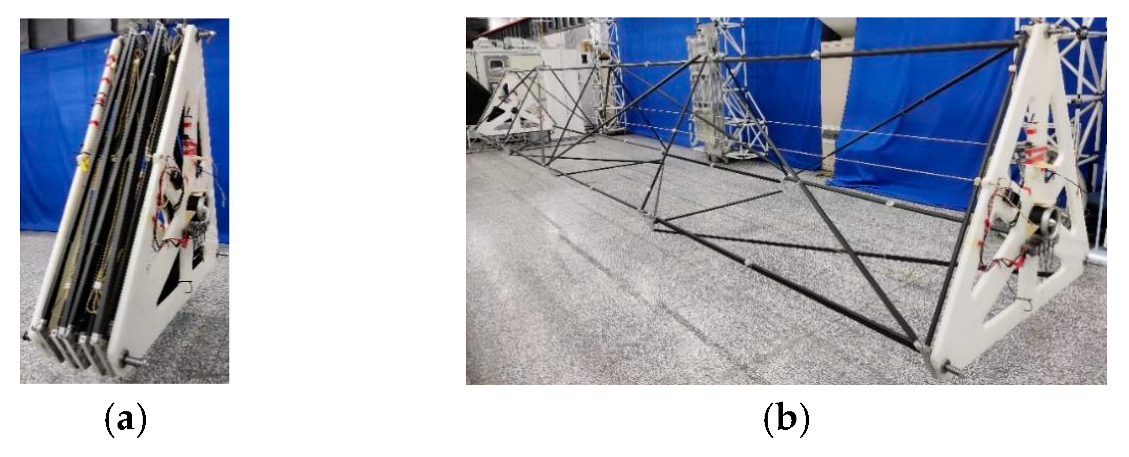
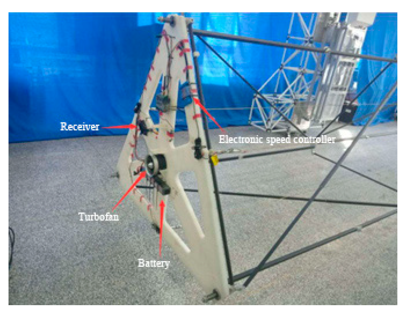
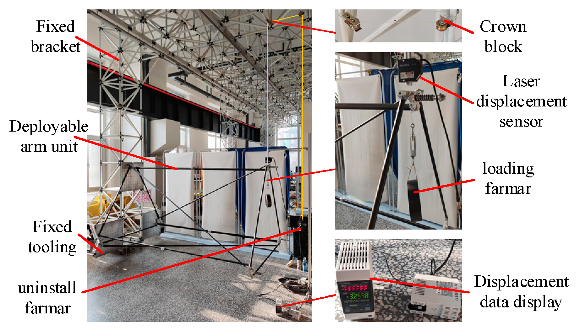
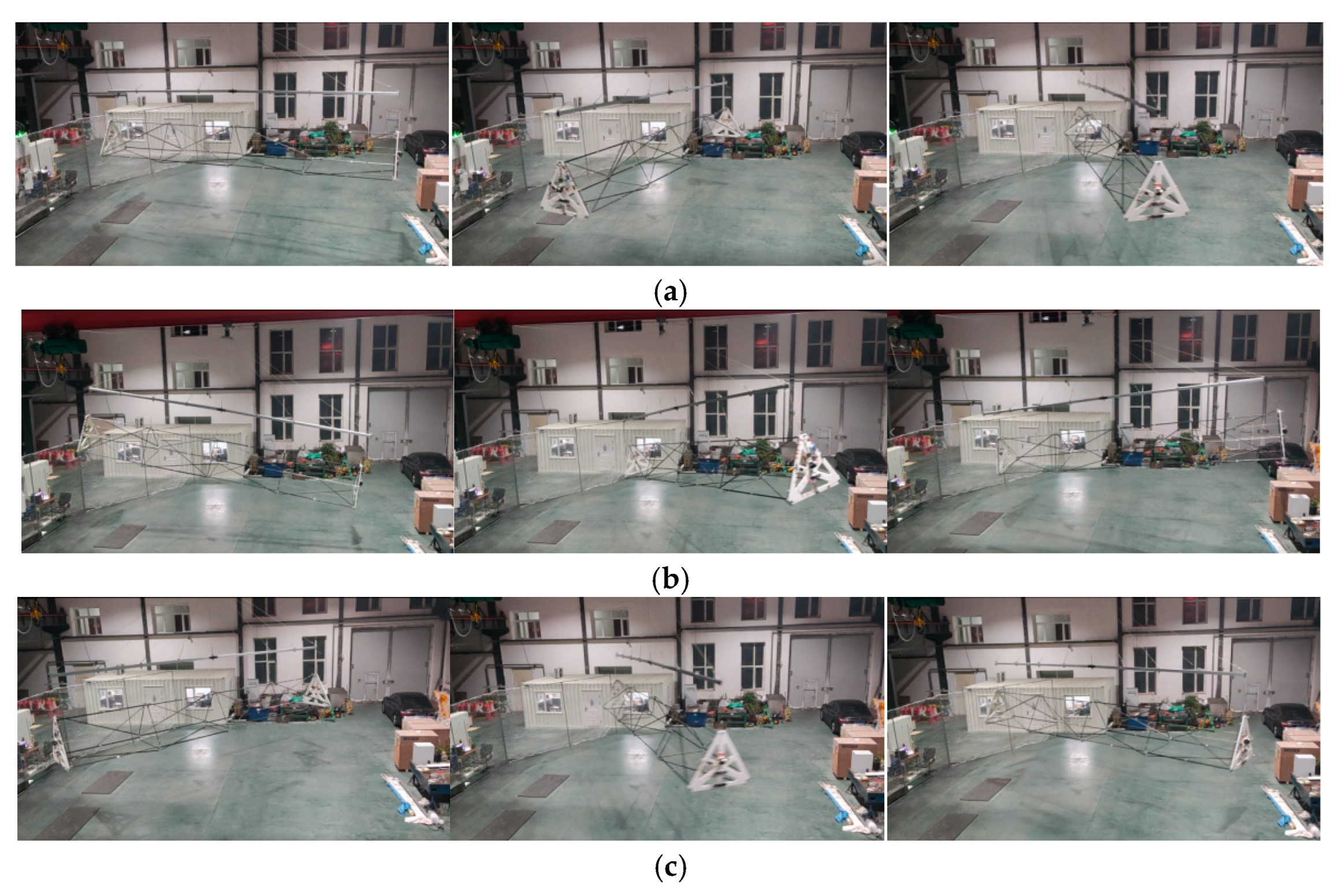
Section 4 explores the effect of various disturbances on the posture of the rigid-body model of the deployable arm during the rotation process; and in the final section, a 10 m 4-unit proportional prototype is developed. On the basis of this prototype, the mechanical characteristics are tested, and a rotating test system is built to verify the correctness of the theoretical analysis.
3. Simulation Analysis of Deployment Driving Characteristics of a Deployable Arm
The whole deployable arm adopts a modular design. Therefore, the movement relationship between its units is similar. To reduce the modeling workload and shorten the simulation time, we use the same four units as the subsequent prototype for simulation analysis. ADAMS is selected to simulate the drag deployment process of the deployable arm, and the original model is simplified accordingly. The diagonal rod, the messenger rope, the taper pin, and other parts are removed. We regard the end support adapter plate and the triangular frame as a whole and retain the original positions of each deployable rod to ensure correct simulation. The driving strategy of the front dragger is studied and optimized through the dynamic simulation of the deployment process.
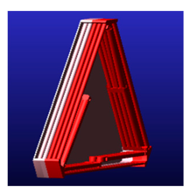
Figure 9 shows the simplified dynamic simulation model of the deployable arm.
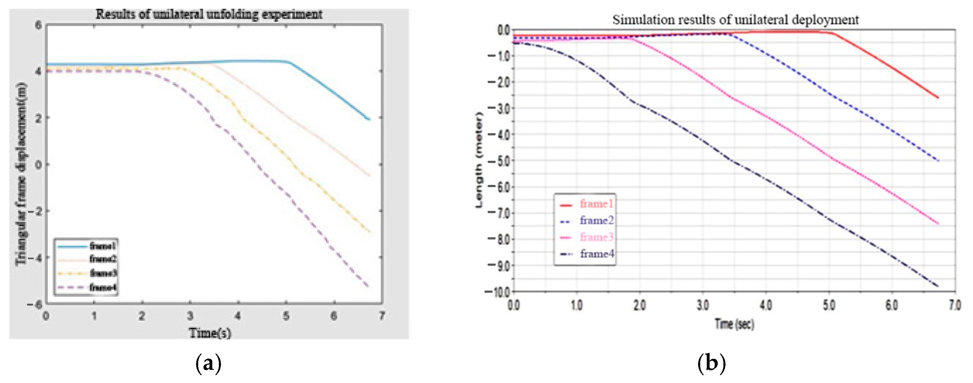
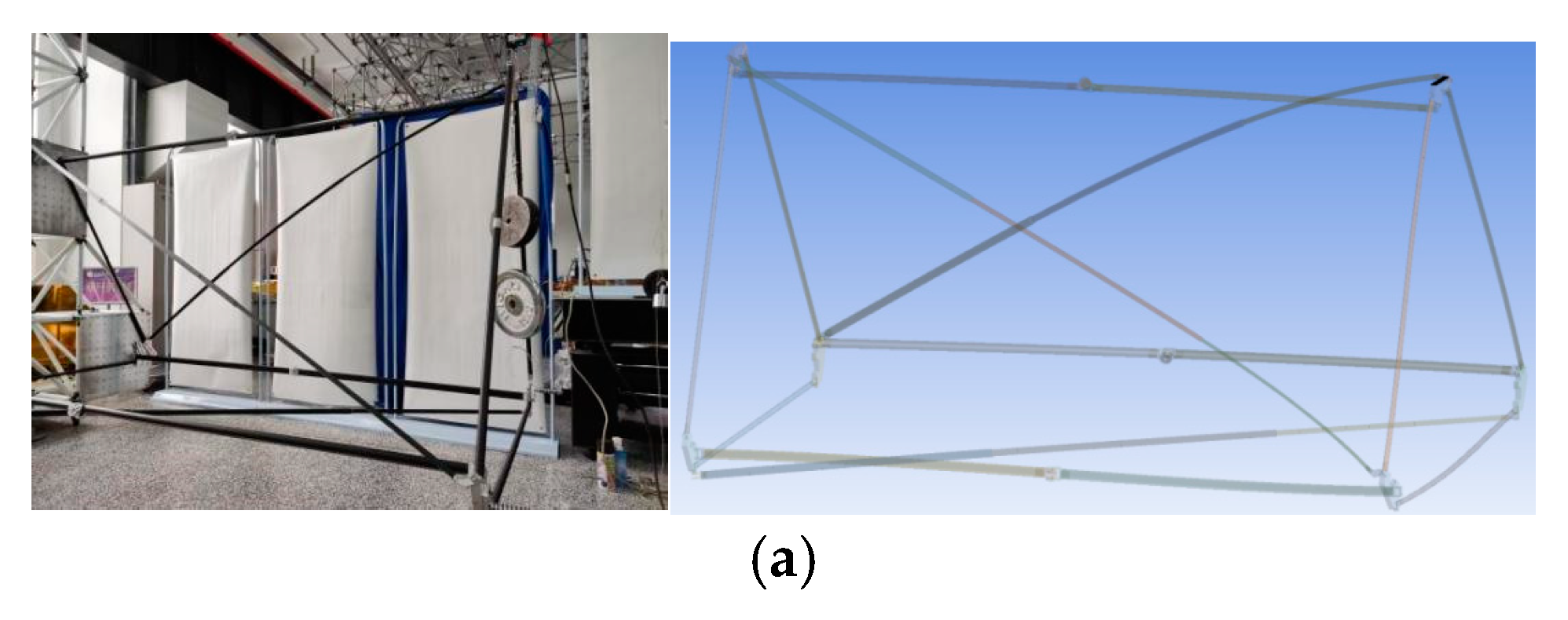
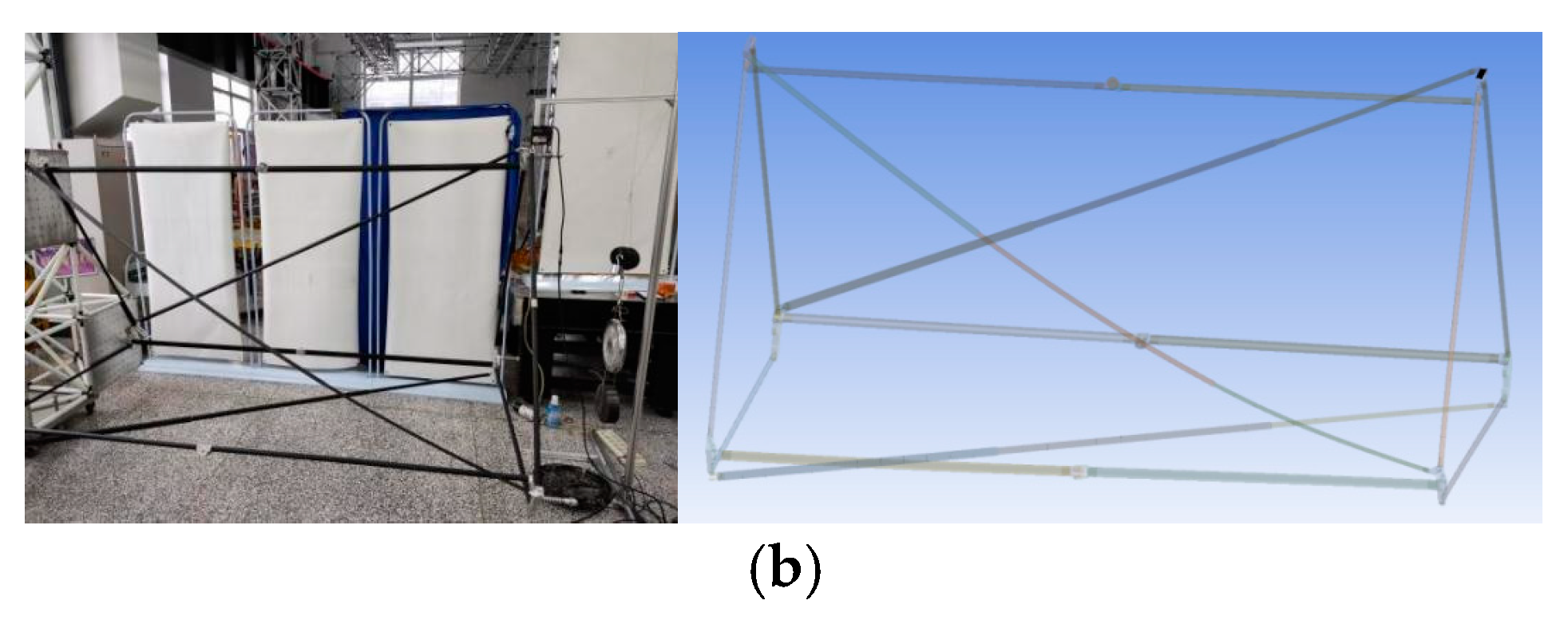
Figure 10 shows the expanded model. The right end of the deployable arm is fixed on the ground, and an axial tension is exerted on the mass center of the left end to simulate the real situation when the deployable arm is deployed on one side for comparison with the test.
To ensure the authenticity of the ADAMS simulation, collision contact is added between triangular frames. The folding rod is extended in place and locked by the locking torque set on the hinge, and the BISTOP double side collision function is selected as the locking torque. At the beginning of the deployment, the locking torque is disabled. The sensor detects that when the folding rod extends to 180°, the locking torque is activated, and the angle between the folding rods is maintained in a small range to simulate the locking process. Because the simulation involves the activation and failure of sensors and moments, the whole simulation process is realized through script simulation.
Investigation reveals that the main driving modes of the dragger are constant tension drive, single-pulse tension drive, and multiple-pulse tension drive. Therefore, dynamic simulation is used to compare the advantages and disadvantages of the three driving modes and a simple and reliable driving scheme suitable for engineering use is selected.
3.1. Constant Tension Drive
Constant pulling force driving simulation is realized by applying a constant pulling force at the moving end of the object. For this simulation, a constant tension of 20 N is selected.
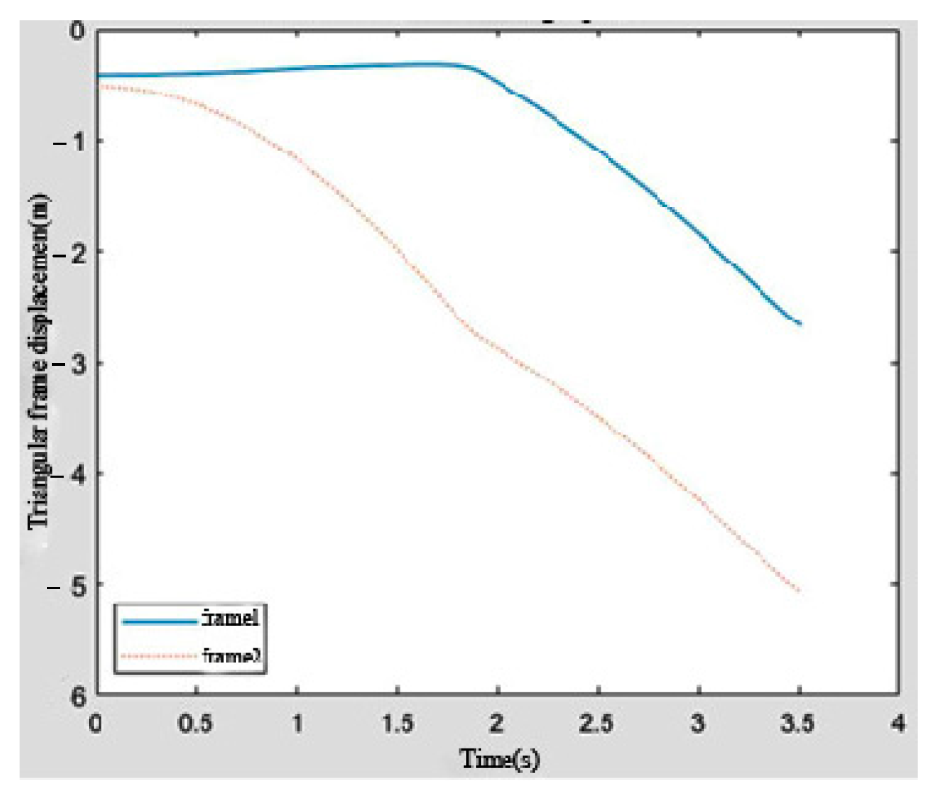
Figure 11 shows the displacement curve of the mass center of each triangular frame. The collision force between the triangular frames causes the triangular frame to expand to a small extent in the early stage of the simulation process, resulting in a small fluctuation in the displacement curve in the early stage of the simulation, but the fluctuation disappears with the gradual expansion of the deployable arm. Each unit of the deployable arm is deployed step by step. After one unit is locked, the following unit can be deployed normally and the deployment time interval for each unit is relatively close. The locked unit moves at a nearly constant speed.
Figure 12 presents the speed curve of the triangular plate. It can be seen that when each unit is locked, a strong impact force will be generated to reduce the speed of the expanded unit and then continue to expand the next unit. Due to the impact force and tension, unlocked units will be deployed to a small extent during the deployment of the previous unit, which is similar to the deployment process in the actual test. When the unit is locked, the speed will fluctuate to a certain extent because of the form of the locking torque. However, the impact is small and can be ignored.
By changing the constant tension, a curve between the driving tension and the time required for deployment can be obtained, as shown in
Figure 13. As the driving tension increases, the time required for deployment gradually shortens and the curve also tends to be flat, indicating that when the tension is greater than a certain value, the increase in tension will have less and less impact on the deployment time.
3.2. Single-Pulse Tension Drive
A single-pulse tension drive means that at the beginning of the deployment process, a pulse tension is applied, which disappears after a period of time, and the deployable arm is gradually deployed through its own inertia. The duration of the pulse force is set as 1 s, and the size is set as 20 N. The simulation results are shown in
Figure 14 and
Table 1. After the pulse force disappears, the speeds of the units when they are deployed are similar and nearly uniform. The time required for the deployment of each unit increases gradually due to the decrease in inertia.
Figure 15 presents the speed curves of all units during deployment. It can be seen that the speed curve is similar to the speed curve under constant tension, except that after the pulse disappears, the deployment speed is much slower than that under constant tension. As the unit produces a resistance after locking, the overall deployment speed also reduces after the unit is locked, leading to a significant decrease in the overall deployment time. However, as the deployment speed continues to decline, the impact during locking also continues to decrease.
Figure 16 displays the relationship curve between the deployment time of the deployable arm and the duration of a single-pulse force. As the duration of the pulse force increases, the deployment time of the deployable arm decreases but the curve tends to be flat, which means that when the duration of the pulse force increases to a certain value, the impact of increase on the deployment time will become smaller.
3.3. Multiple-Pulse Tension Drive
Multiple-pulse tension means that multiple single-pulse forces are applied successively at the moving end. The multiple-pulse tension is set as five times in total, with a time interval of 0.5 s, a duration of 0.5 s, and a size of 20 N. A schematic diagram of multiple-pulse tension is shown in
Figure 17.
As shown in
Figure 18 and
Figure 19 and
Table 2, during the deployment of the deployable arm driven by multiple-pulse pulling, the deployment time interval of each unit is similar, the speed of each unit is nearly constant when it is deployed, and the change trend of the speed curve is similar to that driven by a constant pulling force.
As a result of multiple pulses, the curve fluctuates, and the development time is relatively longer. When the pulse force is applied, the speed increases rapidly and the development time shortens. After the force disappears, the acceleration decreases and the speed increases slowly. The speed changes in a periodic trend.
The above simulation analysis shows that the deployment process of constant tension is relatively gentle, but its driving efficiency is low. The engine power required for a single pulse is less, but the impact during the deployment process is greater, so the deployable arm must have a specific stiffness. Multiple pulses have good comprehensive performance but are difficult to control. After due consideration, constant tension is finally selected as the driving mode of the deployment process. This driving mode has simple control, a smooth deployment process, and high reliability.
4. Rotational Disturbance and Posture Analysis of the Deployable Arm
4.1. Establishment of the Rigid-Body Dynamic Model of the Deployable Arm
Two small engines, one installed at each end, provide thrust to form a force couple and drive the deployable arm to rotate. During the rotation process, factors such as the magnitude of thrust change, the deviation of the thrust direction, and the difference in the mass of the load at the two ends may disturb the rotation process and affect the rotation attitude of the deployable arm. Therefore, it is necessary to study the effect of different disturbances on the rotation posture of the deployable arm.
According to the above finite element analysis results, it can be seen that the deployable arm has high rigidity during spatial rotation and the deformation is small enough. For analysis, the deployable arm can be simplified as a rigid beam, which is conducive to simplifying the analysis model and improving the analysis efficiency.
To simulate the change in the posture of the deployable arm in the space environment, ADAMS software was used to perform rigid-body dynamics modeling, and the model is shown in
Figure 20. The mass of the deployable arm is 100 kg, the effective load at each of the two ends is tentatively set to 300 kg, and the total length of the truss section is 50 m.
4.2. Ideal Rotation
As shown in
Figure 21, two unidirectional forces in opposite directions are applied to the two ends of the load to form a force couple, which drives the deployable arm to rotate in space. Moreover, the load mass at each of the two ends is the same, the mass of the deployable arm is uniform, and the center of mass coincides with the geometric center. This is the rational state of the spatial rotation of the deployable arm without any disturbance.
In the ideal state, the two unidirectional forces have the same magnitude, and the direction of force action is parallel, i.e.,
. To obtain the equivalent moment of force acting on the center of mass, we equivalently translate the driving forces at both ends toward the center of mass (geometric center) as follows:
On the basis of theoretical mechanics, we can conclude that in this state, the deployable arm will rotate around the center of mass (geometric center) at a fixed axis and the rotation axis coincides with the
z-axis in the figure. The rotational speed satisfies the following formula:
where
is the angular velocity of the deployable arm around the
z-axis (rad/s);
is the moment of inertia of the deployable arm around the
z-axis (kg)·m
2); and
is the extended arm acceleration time (s).
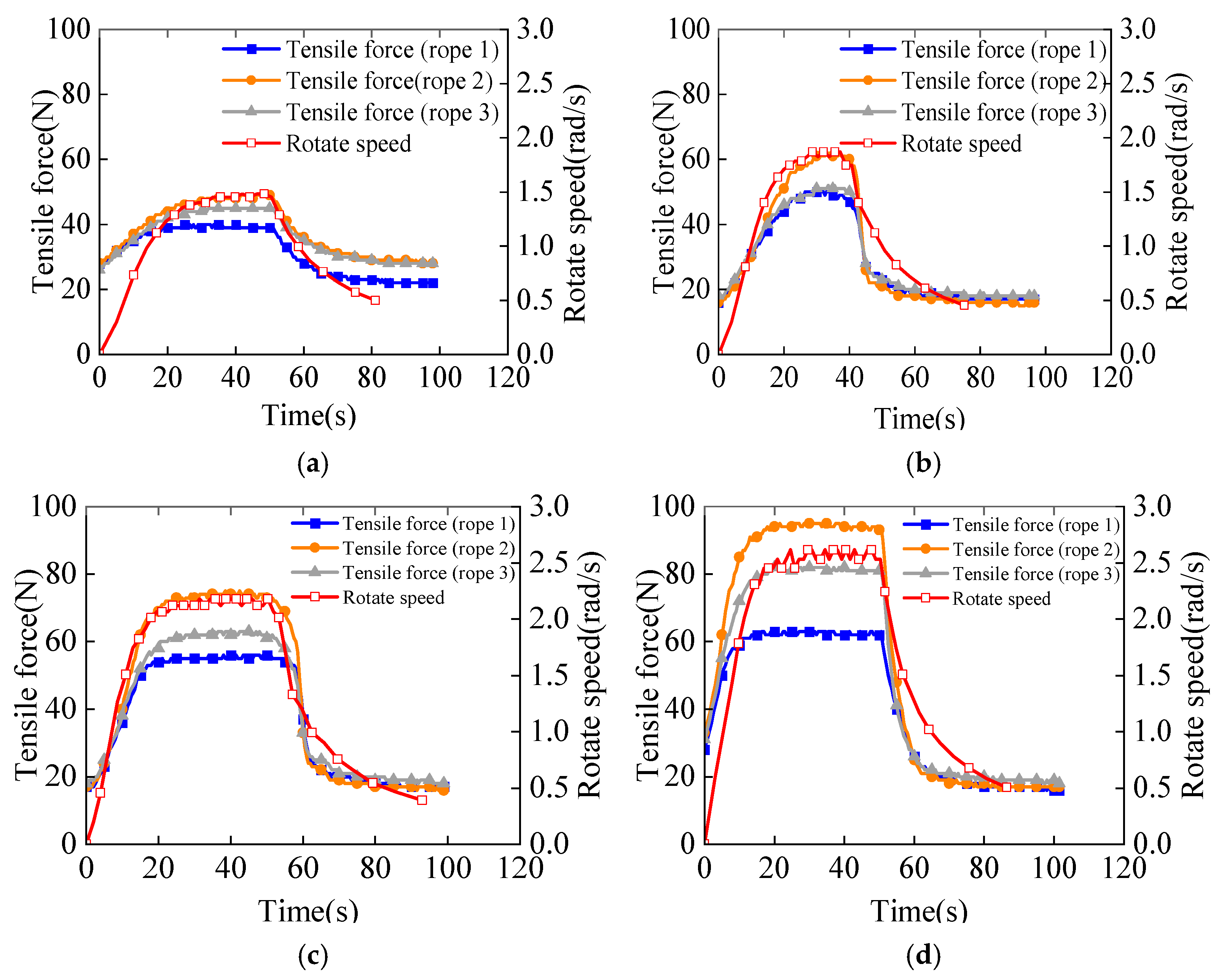
Assuming that the acting time of the driving force couple is 60 s, we calculate the relationship between time and rotation speed under different driving force couples, The results are shown in
Figure 22.
AS shown in
Figure 23, The simulation results show that in the ideal state, the deployable arm rotates around the center of mass (i.e.,
z-axis) and the position of the center of mass does not change, which is consistent with the above analysis.
4.3. Impact of Load Quality
Because the deployable arm is an axisymmetric structure with a uniform mass distribution and a large slenderness ratio, it can be simplified to a homogeneous thin rod in the analysis process to reduce the difficulty of analysis. Considering that in the actual situation, the mass of the load at the two ends may not be completely equal, according to the common sense of mechanics, the unequal load at the two ends will directly influence the position of the center of mass, as shown in
Figure 24.
Let us assume that , in which case, . The mass of the deployable arm is , , and the particle positions are .
By calculating the equivalent centroid position of the multiparticle system, the centroid position can be calculated using the following formulae:
AS shown in
Figure 24 and
Figure 25, assuming the driving forces at both ends
, the force is equivalently translated to the center of mass.
It can be seen that only the force couple is applied at the center of mass and the force couple satisfies the following formula:
When rotating, according to the common sense of mechanics, the deployable arm should rotate around the center of mass. To verify the coincidence of the center of rotation with the center of mass, the position of the center of rotation is determined via calculation. Assume that the position of the center of rotation is . The centrifugal forces at both ends of the rotation center should be equal. Then, the position of the center of rotation can be calculated.
The centrifugal forces of the equivalent mass points of the loads at both ends and the deployable arm are:
where
is equal to the loaded mass point
, which is the magnitude of the centrifugal force relative to the center of rotation (N);
is equal to the loaded mass point , which is the magnitude of the centrifugal force relative to the center of rotation (N);
is equal to the equivalent mass point of the deployable arm , which is the magnitude of the centrifugal force relative to the center of rotation (N);
is the angular velocity of the deployable arm relative to the center of rotation (rad/s).
Let the centrifugal forces at both ends of the rotation center be equal. We obtain the position coordinates of the rotation center:
According to the derivation results, it can be seen that the rotation center coincides with the center of mass; that is, the deployable arm will rotate around the actual center of mass. The motion trajectory curve of the centroid is obtained through simulation analysis, as shown in
Figure 26. The centroid trajectory is a circular trajectory with the centroid as the center, which verifies the correctness of the above analysis.
4.4. Impact of Thrust
During the spin-up process of the deployable arm, the thrust of the two engines may be inconsistent, influencing the spatial rotation attitude of the deployable arm. The effect of this disturbance on attitude was explored by controlling variables. The load mass at each of the two ends of the deployable arm is assumed to be the same, as are the driving forces at both ends, i.e.,
,
, and
, as shown in
Figure 27.
When the driving forces at both ends are equivalently shifted to the center of mass, the center of mass of the deployable arm is subjected to an equal-force couple and a unidirectional force and satisfies the following formulae:
As shown in
Figure 28, the direction of the unidirectional force changes with the rotation of the deployable arm. In addition, due to the fixed axis generated by the high-speed rotation, the rotation axis of the deployable arm is always perpendicular to the
xy plane during the rotation process. The center of mass trajectories under different forces
are obtained by dynamic simulation analysis.
According to the centroid trajectory curve obtained from the simulation analysis, the centroid position of the deployable arm shifts under the disturbance. When increases, the offset of the centroid increases. Moreover, the offset of the centroid in the xy plane is relatively large, ranging from several meters to tens of meters, and the offset in the yz plane is relatively small (no more than 1 m).
The offset direction is related to the initial direction of . When the initial direction of points to the positive direction of the y-axis, the direction of in the initial rotation of the deployable arm points to the first quadrant of the xy coordinate plane, so the initial velocity in the first quadrant is obtained, shifting the center of mass to the first quadrant. Similarly, when the initial direction of points to the negative direction of the y-axis, the direction of in the initial rotation of the deployable arm points to the third quadrant of the xy coordinate plane, so the initial velocity in the third quadrant is obtained, shifting the center of mass to the third quadrant.
4.5. Effect of the Thrust Direction in the xy Plane
Considering the installation accuracy of the engines at both ends, the thrust directions of the engines may deviate, as shown in
Figure 29. Assuming that the magnitude of the thrust is the same, there is a certain angular deviation of the thrust direction in the
xy plane, i.e.,
.
The relationship between force and torque is as follows:
As the angle changes, the unidirectional force will also change and, at the same time, the force is coupled. The magnitude will also change, influencing the acceleration process of the deployable arm.
Through the simulation analysis, we obtain the trajectory curve of the center of mass, as shown in
Figure 30. As the angle
increases, the following factors increase: the magnitude of the unidirectional force; the kinetic energy provided by the unidirectional force to the center of mass; the obtained offset speed; and the total offset distance. Moreover, the offset distance in the
xy plane is relatively large, i.e., in the order of tens of meters, but does not exceed 0.5 m in the
yz plane.
The offset direction depends on the one-way force at the center of mass. The initial direction is the direction of the initial velocity generated at the initial stage of the unidirectional force. The rotation axis of the deployable arm is always parallel to the z-axis due to the fixed axis generated by the spin. In summary, we can see that the disturbance generated by the angle mainly affects the position of the centroid in the xy plane.
4.6. Effect of the Thrust Direction in the yz Plane
As shown in
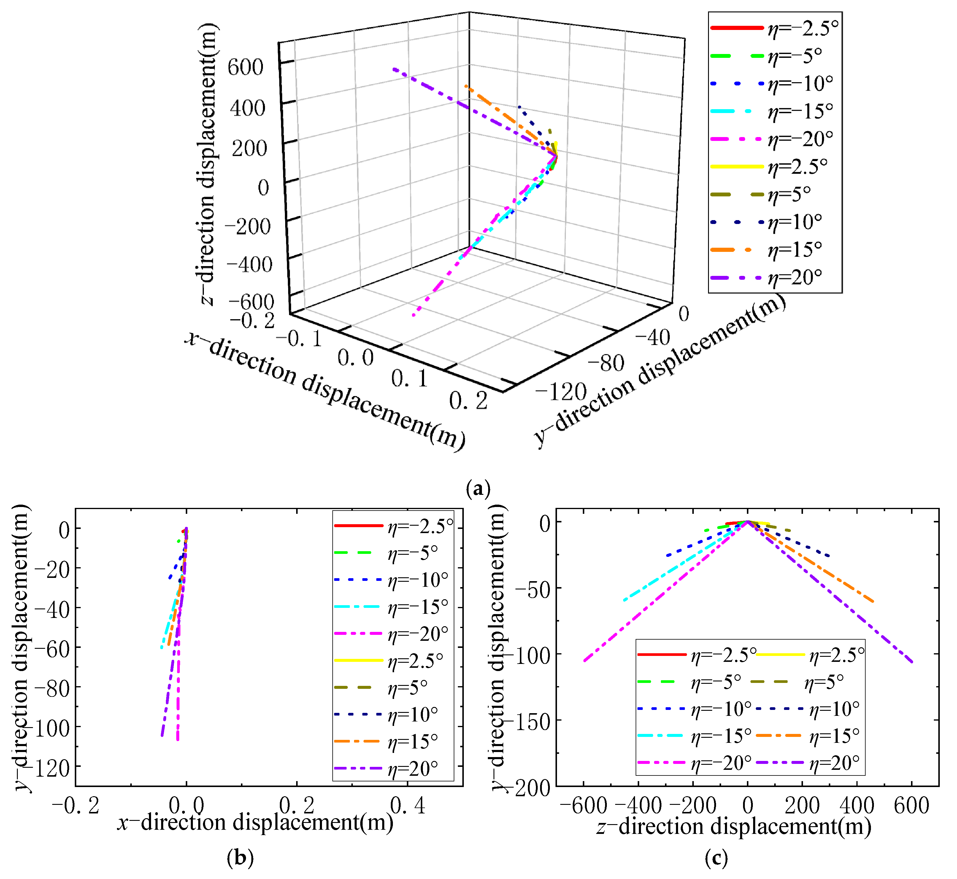
Figure 31, assuming that the magnitude of the thrust is the same, there is a certain angular deviation in the direction of the thrust in the
yz plane, i.e.,
,
.
By equivalently translating the driving forces at both ends toward the center of mass, one unidirectional force and a force couple can be obtained, which satisfy the following formulae:
In addition, the direction of the force couple M coincides with and is opposite to that of the force ; that is, when the extended arm rotates under the action of the force couple, it is subjected to a unidirectional force along the axis of rotation.
As shown in
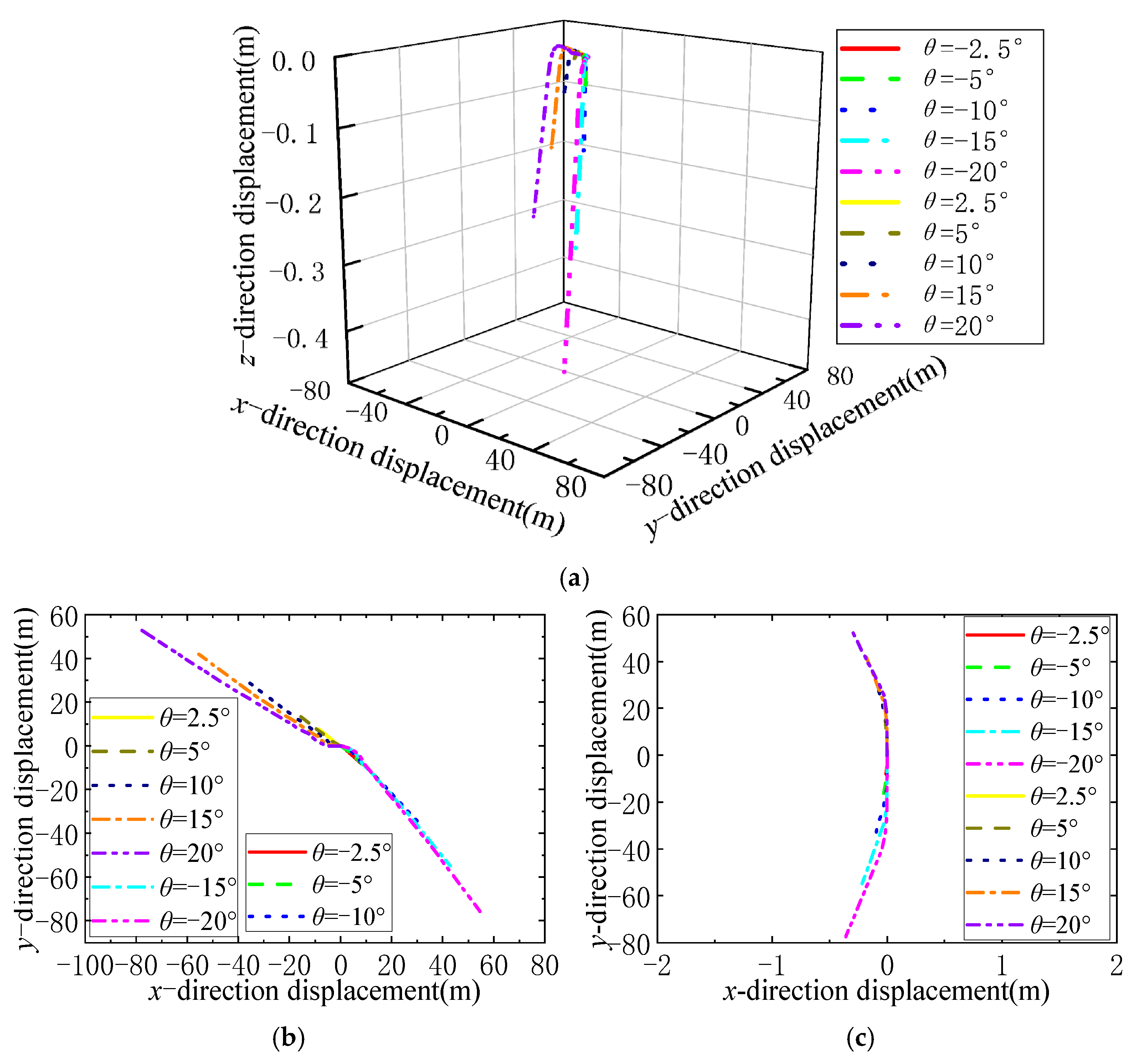
Figure 32, the centroid of the deployable arm translates along and rotates in the direction indicated by the force
as the rotation axis. The trajectory of the loads at both ends is helical, and the trajectory of the center of mass is close to a straight line.
4.7. Sensitivity Analysis of Influencing Factors
According to the above analysis, there are two main sources of disturbance during the rotation of the deployable arm: (1) the disturbance caused by the uneven distribution of the load mass of the deployable arm, which is a structural error and can be eliminated by ground adjustment and trimming; and (2) the disturbance caused by the magnitude and direction deviation of the driving engines at both ends, which can be eliminated by adjusting the engines during the ground test. To facilitate a comparison and analysis, the ratio of the offset distance of the centroid of the deployable arm under the disturbance action to the given reference value is taken as the evaluation standard. Therefore, the sensitivity of the deployable arm disturbance offset to the change in the thrust parameter of the engine can be expressed as
where
is the reference value of the offset of the centroid of the deployable arm (m);
is the disturbance movement distance of the center of mass of the lower deployable arm (m);
represents the engine-thrust-related parameters (reference value N or deg);
is the amount of change in engine-thrust-related parameters (N or deg).
Using Formula (19), the sensitivity of the centroid offset of the deployable arm caused by three disturbances, namely, the different thrust magnitude, the
xy plane thrust direction deviation, and the
yz plane thrust direction deviation, is calculated and the results are shown in
Table 3.
According to the calculation results, the disturbance generated by the deviation angle of the engine thrust in the yz plane has a much greater impact on the attitude of the deployable arm than other disturbances. High torsional stiffness ensures that the deployable arm avoids yz plane thrust deviation.


