Abstract
The tape spring is a crucial component used in the deployment mechanism of spacecraft, and the lightweight design of the deployment mechanism is currently one of the critical issues that need to be addressed. This paper explores the substitution effect of two different negative Poisson’s ratio honeycomb-corrugated spring structures for use in space-deployable structures. Theoretical and finite element methods demonstrated that the negative Poisson’s ratio honeycomb structure could be equivalent to an orthotropic structure. The cylindrical shell bending theory was adopted, taking into account the nonlinearity of the geometric equation, the influence of cross-sectional deformation and cross-sectional position on the internal force expression, and the influence of the geometric equation to derive expressions for the bending moment and curvature radius during the folding and bending process. Numerical methods were used for comparative analysis. The NSGA-II algorithm optimized the geometric parameters of the negative Poisson’s ratio honeycomb, resulting in the optimal solution under given constraints. The results showed that the Auxetic re-entrant honeycomb structure performed better in bending moment capacity than the Star-shaped honeycomb, and the bending moment capacity of the Auxetic re-entrant honeycomb structure per unit mass was superior to that of the traditional tape spring.
1. Introduction
Deployable structures in space are a critical aspect of space technology, offering a potential solution to the conflict between the structural requirements of large spacecraft and the constraints of rocket launch envelopes [1]. They enable the deployment and retraction of satellites and other spacecraft in space, with numerous applications in the aerospace industry, such as large solar arrays, communication reflectors, telescopes, solar sails, and more [2]. They typically consist of multiply folded hinges, transmission devices, actuators, and controllers. Using deployable spatial structures can expand the space observation range of satellites and spacecraft, increase the exposure area of solar panels, and improve the accuracy of communication and navigation systems [3,4,5,6,7]. The tape spring is a critical technology used in the construction of deployable space structures, offering many advantages such as ease of manufacturing and assembly, a high stiffness-to-mass ratio for deployment, no friction or rebound, low cost, compact design, self-locking feature when fully deployed, self-deployment using stored energy without external power, and resistance to blockage of moving parts due to adverse environmental conditions and long-term storage [8].
Many spacecraft solar panels are deployed using corrugated springs, whose stiffness can be changed. When the solar panel is folded, the stiffness of the corrugated spring is small, while, in its deployed state, its stiffness quickly increases. Sergio Pellegrino [9] examined the uses of a special types of tape springs, which were curved both longitudinally and transversely. It was found that these types of tape springs had similarities to straight ones but also an important difference when it came to equal-sense folds with small rotation angles. This means that if this method is used for packaging a deployable reflector, then full deployment cannot be guaranteed. Mallikarachchi [10] suggested that pinching a hinge can reduce the peak moment required for folding it while increasing its carrying capacity during operation by about double than snapback moments when not pinched at all. Ye [11,12] designed a self-driven and self-locking corrugated spring for deployable space structures under pure bending load through an optimization process and studied a new hinge with three corrugated springs and the optimal substitution model to maximize the steady-state moment and withstand allowable stress. Yang [13] proposed a TRAC boom wrap optimization design method based on response surface theory and parametrically studied the geometric parameters to determine their impact on wrap behavior and complete deployment stability. Yao [14] presented a sensor system for in situ validation of a deployable tape spring hinge’s structure, which consists of an ultra-thin and soft electronic skin. The design, fabrication, and materials of this electronic skin were also described. Wei Chang [15] studied the influence of different geometric parameters on the mechanical performance of corrugated springs and their driving and anti-interference capabilities during the bending process. These studies provided reference values to improve the kinematic accuracy and reliability of deployable structures.
In previous work [16], we explored the possibility of using negative Poisson’s ratio honeycomb structures to substitute for tape springs. In this paper, we further refine the theoretical derivation by considering the influence of section deformation on the internal force equation, the influence of different reference planes on the geometric equation, and the non-linear terms of the geometric equation. We derive a more accurate expression for the curvature radius and bending moment during the bending process of the tape spring. We investigate the mechanical performance of two types of negative Poisson’s ratio honeycomb tape springs through theoretical calculations, comparative analysis using finite element software, and optimization of the honeycomb geometry using the NSGA-II multi-objective optimization algorithm. We determine the optimal parameters for the honeycomb structure tape spring to achieve better mechanical performance with a lighter weight, thus achieving the goal of a lightweight design.
2. Theoretical Analysis of the Folding Process for Honeycomb Negative Poisson’s Ratio Honeycomb Tape Springs Considering Geometric Nonlinearity
2.1. Equivalent Parameters of the Negative Poisson’s Ratio Honeycomb Structure
The traditional range of Poisson’s ratio for materials is between −1 and +0.5 [17]. A negative Poisson’s ratio honeycomb structure is a special type of honeycomb structure that has a Poisson’s ratio of less than zero [18]. Materials and structures that have negative Poisson’s ratios demonstrate a behavior that contradicts our intuition. When subjected to uniaxial compression (or tension), these materials and structures actually contract (or expand) in the transverse direction [19,20], as shown in Figure 1. This structure is often referred to as “auxetic material”. Compared to conventional materials with a positive Poisson’s ratio, negative Poisson’s ratio materials exhibit improved mechanical properties, including (a) in-plane indentation resistance [21,22]; (b) shear strength [23,24,25]; (c) synclastic bending behavior [26,27]; (d) energy absorption [28,29,30,31,32,33,34]; (e) fracture toughness [35]; (f) negative compressibility [36,37,38,39,40]; and (g) sound insulation [41,42,43,44,45,46] Negative Poisson’s ratio honeycomb structures have wide-ranging potential in engineering applications, such as shock absorption, sound insulation, vibration control, piezoelectric materials, and medicine. They can expand and contract in different directions, making them very suitable for manufacturing structures and materials that need to react to external forces [47]. Inspired by the work of KW Hector [48], we attempted to apply honeycomb structures to tape spring structures.
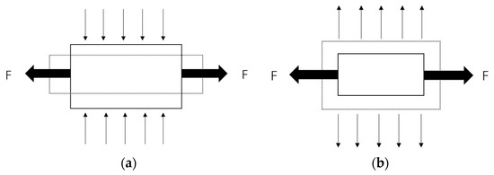
Figure 1.
Different deformation characteristics of positive and negative Poisson’s ratio structures. (a) Positive Poisson’s Ratio. (b) Negative Poisson’s Ratio.
Several studies, such as those by Allen [49], Gibson [50], Burton [51], and Fu [52], have investigated the equivalent parameters of honeycomb structures. We followed Gibson’s approach and treated the honeycomb as an equivalent orthotropic structure. The honeycomb thin-walled structure within the linear elastic range can be modeled as a Bernoulli–Euler beam. Figure 2 shows the unit cells of the two different negative Poisson’s ratio honeycomb structures studied, with their geometric parameters indicated.
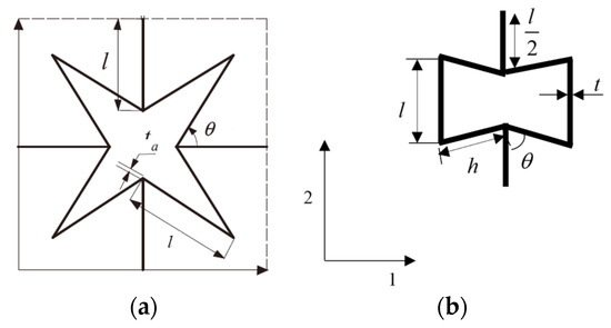
Figure 2.
Different structures. (a) Star-shaped. (b) Auxetic re-entrant.
Equivalent parameters of Star-shaped honeycomb [53]:
Equivalent parameters of Auxetic re-entrant honeycomb [54]:
2.2. Theoretical Analysis of a Moment in the Bending Process Considering Geometric Nonlinearity
2.2.1. Bending Moment of Isotropic Tape Spring for Folding
The bending process of the tape spring is shown in Figure 3, where Figure 3a shows the geometric parameters and Figure 3b shows the curvature radius r and rotation angle θ when a bending moment M is applied.
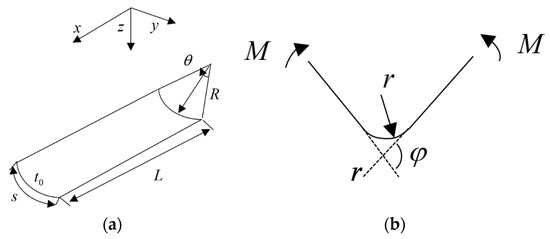
Figure 3.
Diagram of the folding process of the tape spring and geometric parameters. (a) Geometric parameters. (b) Diagram of bending.
The deformation and coordinate system after bending and folding is shown in Figure 4a, with the coordinate system established in the initial state, where the generatrix direction is the x-axis. Taking a small element on the symmetric centerline of the folded and bent structure and drawing its internal force diagram, the coordinate system remains consistent with the initial state, as shown in Figure 4b, where is the normal force and moment in the φ-direction; is the normal force, moment, and transverse force in the y-direction; and is the strain in the φ- and y-directions.
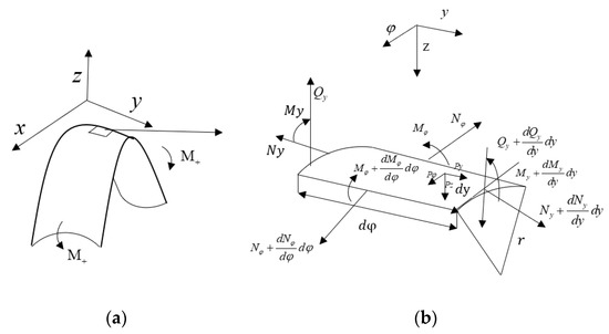
Figure 4.
Micro unit. (a) Folding. (b) Force diagram.
For the isotropic tape spring, considering geometric nonlinearity, the equilibrium equation for the unit shown in Figure 4b is established as follows:
Based on the large deformation of folding, the non-linear geometric equation of the cylindrical shell is considered as follows:
The constitutive equation for stress and strain at any point within an isotropic elastic body is given by:
Substitute the geometric equation into the constitutive equation to obtain the stresses and mid-surface internal forces expressed by displacement.
This considers the trapezoidal shape of the cross-section of the shell element at y as constant, which is represented by the factor in Equations (12) and (14). The different lengths of circumferential fibers at different elevation levels z are also considered, represented by the appearance of the denominator in Equations (10) and (11).
Let:
If , then:
Therefore, from (13), we can obtain the following:
Then, (14) simplifies to:
Substitute (15) and (19) into (4):
As , assuming , substituting into the above equation:
The solution to the equation is:
Considering the symmetry of the shell :
Let , on the boundary of , .
Obtain:
Assuming the bending moment M required for driving the bending process of the belt spring can be calculated by integration.
As can be seen from the bending moment expression (25), it can be seen that the magnitude of the moment is related not only to the curvature radius r but also to the material parameters E and v, as well as the central angle θ and the thickness t of the cross-section. Substitute geometric parameters are R = 350, theta = 90°, t = 0.3 mm, material parameters elastic modulus E = 210 GPa, and Poisson’s ratio v = 0.3. When subjected to a reverse bending moment, the initial stage of a belt-type spring can be observed in Figure 5, where the required driving moment increases sharply with the increase in the angle to 6664.5 Nmm. This value is called the critical bending moment, which reflects the anti-interference ability of the tape spring. After this stage, its stiffness rapidly decreases, and the bending moment eventually reaches a certain value of 956.5 Nmm. This value is called the steady-state bending moment.
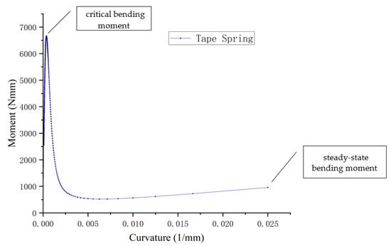
Figure 5.
The curvature–moment curves for the bending process of tape spring.
By taking L = 350 mm, R = 35 mm, , and , we can substitute the model parameters into Equation (25) to obtain the variation in curvature radius–bending moment during the reverse bending process of the tape spring structure with different central angles and thicknesses, as shown in Figure 6 and Figure 7. For Figure 6, the x-axis represents the reciprocal of the curvature radius, the y-axis represents the central angle, and the z-axis represents the bending moment. It can be seen that the critical bending moment of the open-ended cylindrical shell tape spring increases significantly with the change in the central angle θ. In contrast, the steady-state bending moment remains relatively stable. For Figure 7, the x-axis represents the reciprocal of the curvature radius, the y-axis represents the thickness, and the z-axis represents the bending moment. With the change in thickness t, the critical bending moment of the open-ended cylindrical shell tape spring increases significantly, and the steady-state bending moment also increases significantly.
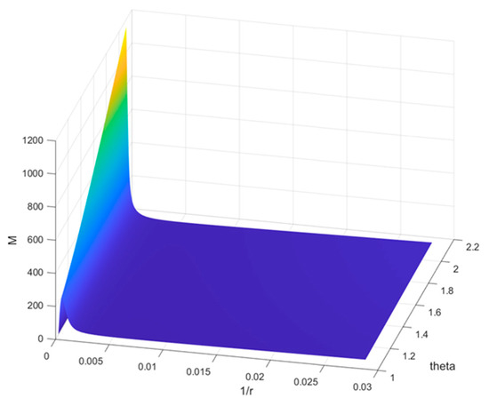
Figure 6.
Curvature radius–bending moment relationship during the bending process of tape-spring structures with different central angles.
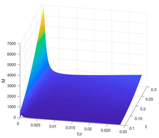
Figure 7.
Curvature radius-bending moment relationship during the bending process of tape-spring structures with different thicknesses of the cross-section.
2.2.2. The Folding Moment of Negative Poisson’s Ratio Honeycomb Tape Spring
To convert the negative Poisson’s ratio to the cellular topology, which is equivalent to an orthotropic shell, Formulas (1) and (2) are used. The cylindrical coordinate system, shown in Figure 8, is employed. Assuming that the membrane force per unit width of the shell is N(), the internal bending force per unit width is M(), the mid-plane strain is , and the mid-plane deflection is (). Then, the conversion is conducted.
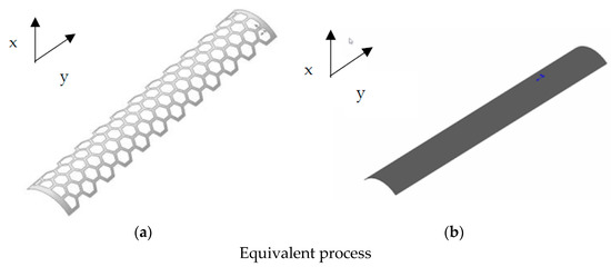
Figure 8.
Tape spring with honeycomb structure. (a) Honeycomb structure. (b) Orthotropic structure.
The equilibrium equations are consistent with isotropy (5) (6):
Geometric equation:
Let , then
Constitutive equation:
For honeycomb structures, as they can be considered equivalent to single-layer orthogonal anisotropic structures, the constitutive equation can be derived from the constitutive equation of single-layer plates with orthogonal anisotropy:
The expression of internal force in the middle surface:
Substituting the internal force Formulas (34)–(37) into the equilibrium Equations (5) and (6), we obtain a set of non-linear variable-coefficient differential equations in terms of the displacement in the generatrix direction v and the displacement in the normal direction w:
By merging (34) into the balance Equation (4):
Taking the derivative, with respect to , gives:
By merging (34)–(37) into the balance Equation (4):
If , then
Assuming .
Then, (41) results in:
The solution is:
Considering :
on the boundary of ,
Thus, the bending moment M during the bending process is:
Set up the following numerical example. The material parameters and geometric parameters are shown in Table 1.

Table 1.
Parameters of the honeycomb structures.
Upon substituting the parameters into the calculation, the curvature–moment relationship, shown in Figure 9, is obtained. It can be observed that the two types of negative Poisson’s ratio honeycomb structures exhibit a similar variation process, with a steady-state bending moment of 17.2 Nmm for the star honeycomb. In contrast, the steady-state bending moment for the re-entrant honeycomb is 305.7 Nmm, which is significantly different, indicating that the re-entrant honeycomb is a better alternative. Table 2 displays a comparison of the two honeycombs with a regular tape spring.
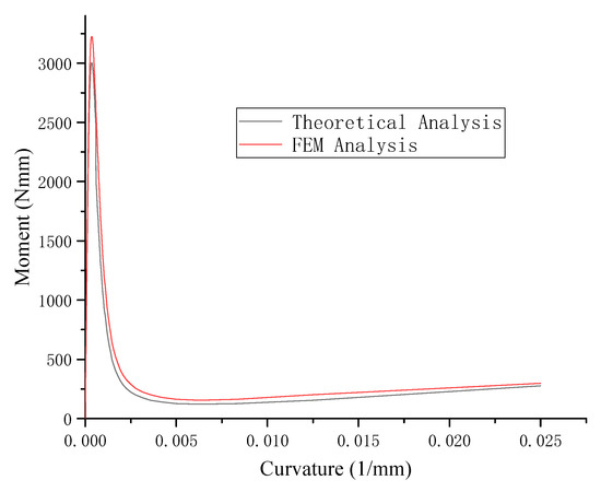
Figure 9.
Comparison of a radius of curvature–moment curves for the bending process of two types of negative Poisson’s ratio honeycomb tape springs.

Table 2.
The comparison of different structures.
3. Multi-Objective Optimization Design
Multi-objective optimization design is a method for solving optimization problems with multiple objectives. In multi-objective optimization, the objectives may conflict or have interrelated relationships. Therefore, multi-objective optimization aims to find a set of solutions that optimally meet all objectives. The methods can be divided into two categories: compromise methods and non-compromise methods. Compromise methods attempt to find solutions that achieve a compromise between all objectives. Non-compromise methods attempt to find a set of solutions that optimally meet all objectives without compromising them. Multi-objective optimization methods are typically based on mathematical optimization theories, such as single-objective optimization, game theory, and computational intelligence. Some standard multi-objective optimization methods include analytical methods, simulated annealing, genetic algorithms, ant colony algorithms, and particle swarm optimization.
Multi-objective optimization has wide applications in multiple fields, such as engineering design, scientific computation, economics, and biology. Multi-objective optimization methods can help us find a set of solutions that meet all objectives optimally in complex environments and achieve a balance between objectives. The NSGA-II is a commonly used multi-objective genetic algorithm and an improved version of the NSGA algorithm. Figure 10 illustrates the structure of the NSGA-II algorithm, which is designed to find the optimal global solution in multi-objective optimization problems. The algorithm incorporates non-dominated sorting technology based on genetic algorithms, which divides the non-dominated levels of individuals in the population to ensure solution diversity in the population [55]. First, the NSGA-II algorithm performs non-dominated sorting to divide the population solutions into layers. Reproduction and mutation operations are carried out on each layer, and the diversity of solutions between layers is maintained using the roulette selection algorithm. The population is then updated and selected through non-dominated sorting and the crowding distance index. In addition to these, the algorithm employs mutation and crossover functions [55]. Among these functions, the crossover is considered the most important in the NSGA-II algorithm [56]. In multi-objective optimization problems, the crossover function is responsible for producing new offspring by merging genetic information from two parents, while the mutation function plays a crucial role in preserving genetic diversity between current and future generations of the population, ultimately leading to the discovery of the optimal global solution [57]. The crowding distance function, as depicted in Figure 11, plays a key role in ensuring diversity and facilitating the selection of solutions in the population.
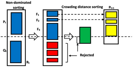
Figure 10.
NSGA-II algorithm structure.
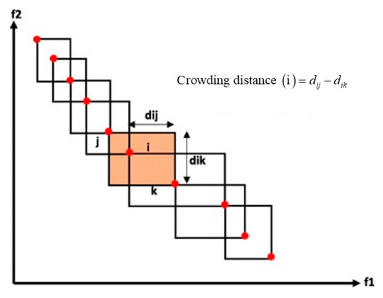
Figure 11.
Structure of crowding distance function.
Lightweight optimization design should not only pursue the minimum quality but also ensure the minimum quality while guaranteeing sufficient mechanical properties of the tape spring. Therefore, the NSGA-II algorithm is used for multi-objective optimization design. From the moment expression (40), it can be seen that the magnitude of the bending moment is not only related to the curvature radius r but also to the material parameters E and v, as well as the size of the honeycomb cells. Therefore, we will conduct research on honeycomb cells. This article takes the steady-state bending moment M, honeycomb mass Mass, and unit bending moment value Unit as the objective functions for optimization, with the geometric parameters of the honeycomb structure tape spring as the design variables. The optimization process is shown in Figure 12. For ease of calculation, the honeycomb mass is taken as the mass of a single cell, with a density of unit density. According to (1), (2), and (39), the optimization model of the auxetic re-entrant honeycomb tape spring can be obtained as follows.
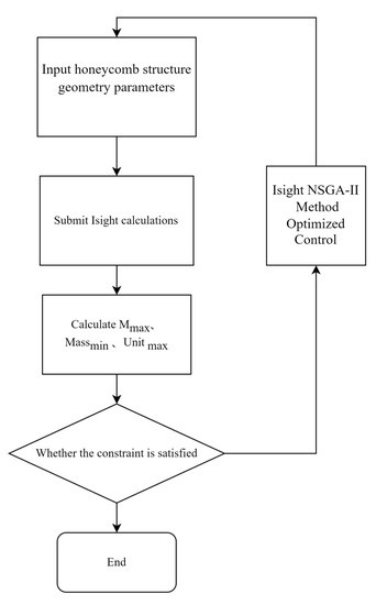
Figure 12.
NSGA-II algorithm flowchart.
Figure 13 shows the Pareto chart obtained during the optimization process, which reflects the percentage of contribution of each item in the fitted model to each response. It can be seen that the honeycomb inner wall thickness t0 has the greatest influence on the bending moment, followed by .
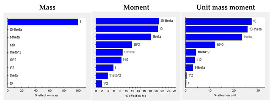
Figure 13.
Pareto chart.
Table 3 shows that the optimized model has a significantly improved unit bending moment compared to the original design, with the unit bending moment of the Auxetic re-entrant honeycomb increasing from 18.57 to 20.46, an improvement of 10.1%.

Table 3.
Optimization results.
4. Numerical Argument Analysis
After optimization analysis, in order to verify the correctness of the optimization analysis, the reverse bending process simulation was performed using ABAQUS software by creating a finite element model with shell element S4R5. In order to ensure that the space-deployable mechanism model can achieve a purely bending state during actual operational processes, we used MPC constraints to establish nodes on both ends of the model, with the centroid of the end face serving as the control node and coupled them as MPC constraints. In the ABAQUS finite element software, we applied boundary conditions at the end face’s centroid to simulate the bending moment’s loading effect. We used the ABAQUS automatic meshing feature, with an approximate global size of 0.5 mm and a maximum offset factor of 0.1 for curvature control. We also set the minimum size control as a proportion of the global size, with a factor of 0.1. In the finite element analysis process, we employed a large non-linear deformation (NLGEOM) incremental analysis using a solution on which the method was based on. The automatic stabilization coefficient STABILIZE was set to 0.0002. The boundary conditions with applied displacement constraints were as follows: among the six degrees of freedom on one end face of the model, the X-direction displacement, Y- and Z-direction displacements, and rotations were constrained, and an X-direction rotation of 1.57 radians was applied, i.e., an X-direction rotation of 1.57 radians was applied while the other five degrees of freedom were constrained. For the other end section, the X- and Y- direction displacements were constrained, the Y- and Z- direction rotations were constrained, and an X-direction rotation of −1.57 radians was applied. This application could make the model bend into a U-shape, which was consistent with the actual working state of the space unfolding mechanism. The model dimensions are shown in Table 4. The boundary conditions are shown in Table 5. The FEM model is shown in Figure 14.

Table 4.
Geometry parameters.

Table 5.
Boundary conditions.

Figure 14.
Finite element model of Auxetic re-entrant honeycomb tape spring.
Figure 15 displays the finite element model of the Auxetic re-entrant honeycomb tape spring after bending. In the finite element model, at the mid-point of the shell, as shown in Figure 16, the adjacent three points A(x1,y1), B(x2,y2), and C(x3,y3), are taken. Assuming that the coordinates of the three points are known, the curvature radius r during the bending process of the tape spring can be calculated by Formula (42)
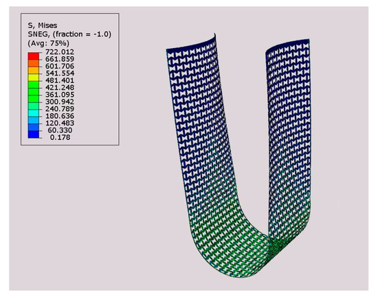
Figure 15.
The finite element model for folding and bending of the optimized Auxetic re-entrant honeycomb structure.
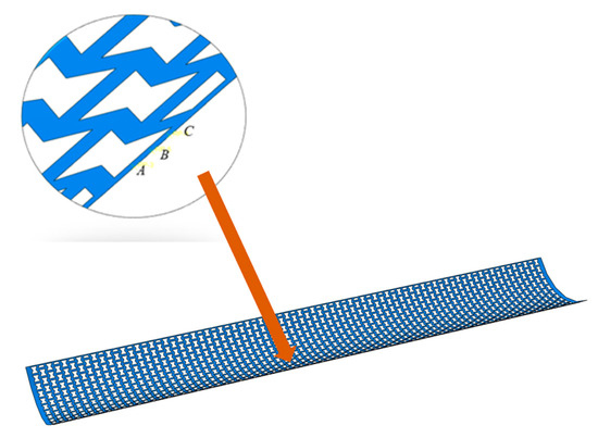
Figure 16.
Reference points for the finite element model.
Among:
The corresponding curvature radius–bending moment diagrams were obtained by extracting the coordinates of points A, B, and C in the finite element model and analyzing the changes in the coordinates.
By substituting the optimized honeycomb model parameters from Table 3 into the bending moment expression (40), we obtain the theoretical analysis curve. The FEM analysis curve was extracted from the finite element model results, as shown in Figure 17. The steady-state bending moment value of the optimized Auxetic re-entrant honeycomb in the finite element results was 310.1 Nmm, which was only 2.8% different from the theoretical optimization result. The curvature radius–bending moment relationships of different models from finite element simulations and theoretical predictions were compared. A good correlation between the two results was found, proving the rationality of the theoretical derivation.
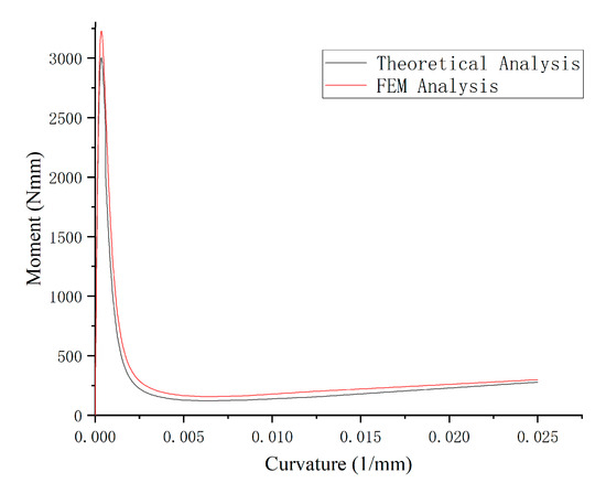
Figure 17.
Comparison of theoretical and finite element analysis of moment–curvature curves.
5. Conclusions
This paper analyzed and calculated the mechanical properties of isotropic spring structures during folding and bending. We established a non-linear control equation for folding and bending to obtain an exact expression for the folding and bending displacement. We plotted the curvature–bending moment characteristic curve and analyzed the geometric dimensions that affected the bending moment. As the cross-section’s central angle θ changed, the spring’s critical bending moment increased significantly, while the steady-state bending moment remained relatively close. For changes in thickness t, both the critical and steady-state bending moments of the spring increased significantly. We further analyzed orthotropic honeycomb spring structures based on the research of isotropic spring structures. Based on the orthotropic shell bending theory, we derived a bending moment calculation formula for orthotropic honeycomb topology tape springs with geometric nonlinearity. The formula demonstrated the relationship between the curvature radius and a bending moment of negative Poisson’s ratio honeycomb tape springs during folding and bending processes. Finite element models of re-entrant and star-shaped negative Poisson’s ratio honeycomb structures were established and compared with theoretical predictions to verify the correctness of the theory. The NSGA-II multi-objective optimization analysis algorithm was used to optimize and analyze the honeycomb parameters, and the optimal solution under the given conditions was obtained. The mechanical performance of the re-entrant honeycomb tape spring was improved by 10.1% after optimization. The results showed that the inherent negative Poisson’s ratio properties of the re-entrant honeycomb structure had the potential for application in folding space unfolding mechanisms and could achieve the same mechanical properties as regular tape springs with lighter weight.
Author Contributions
Conceptualization, Y.Y. and F.W.; methodology, Y.Y. and F.W.; software, Y.Y.; validation, Y.Y. and J.L.; writing—original draft preparation, Y.Y.; writing—review and editing, Y.Y., F.W. and J.L.; visualization, Y.Y.; supervision, F.W.; project administration, F.W.; funding acquisition, F.W. All authors have read and agreed to the published version of the manuscript.
Funding
Supported by the Key Laboratory of Disaster Forecast and Control in Engineering (Jinan University), MOE of China.
Data Availability Statement
The data presented in this study are available on request from the corresponding author.
Conflicts of Interest
The authors declare no conflict of interest.
Nomenclature
| Symbol | Description |
| E1, E2 | Elastic modulus |
| v12, v21 | Poisson’s Ratio |
| Nx, Ny, Nφ | Normal force |
| Mx, My, Mφ | Moment |
| Qx, Qy | Transverse force |
| εx, εy, εφ | Strain |
| σx, σy, σφ | Stress |
References
- Ma, X.; Li, T.; Ma, J.; Wang, Z.; Shi, C.; Zheng, S.; Cui, Q.; Li, X.; Liu, F.; Guo, H.; et al. Recent Advances in Space-Deployable Structures in China. Engineering 2022, 17, 207–219. [Google Scholar] [CrossRef]
- Yildiz, K. Cable Actuated Tensegrity Structures for Deployable Space Booms with Enhanced Stiffness; The Pennsylvania State University: State College, PA, USA, 2018. [Google Scholar]
- Lan, X.; Liu, L.; Zhang, F.; Liu, Z.X.; Wang, L.L.; Li, Q.F.; Peng, F.; Peng, F.; Hao, S.D.; Dai, W.X.; et al. World’s first spaceflight on-orbit demonstration of a flexible solar array system based on shape memory polymer composites. Sci. China Technol. Sci. 2020, 63, 1436–1451. [Google Scholar] [CrossRef]
- Ma, S.; Liang, B.; Wang, T. Dynamic analysis of a hyper-redundant space manipulator with a complex rope network. Aerosp. Sci. Technol. 2020, 100, 105768. [Google Scholar] [CrossRef]
- Li, C.; Wang, Z.; Xu, R.; Lv, G.; Yuan, L.; He, Z.; Wang, J. The Scientific Information Model of Chang’e-4 Visible and Near-IR Imaging Spectrometer (VNIS) and In-Flight Verification. Sensors 2019, 19, 2806. [Google Scholar] [CrossRef] [PubMed]
- Nie, R.; He, B.; Yan, S.; Ma, X. Design optimization of mesh antennas for on-orbit thermal effects. Int. J. Mech. Sci. 2020, 175, 105547. [Google Scholar] [CrossRef]
- Firth, J.A. Deployment Mechanisms for Rollable Spacecraft Booms; North Carolina State University: Raleigh, NC, USA, 2019. [Google Scholar]
- Arora, H.; Dangarwala, R.; Mukherjee, S.; Munjal, B.S. Investigation of tape flexures for space borne deployable structures. Int. J. Space Struct. 2022, 37, 37–48. [Google Scholar] [CrossRef]
- Seffen, K.; You, Z.; Pellegrino, S. Folding and deployment of curved tape springs. Int. J. Mech. Sci. 2000, 42, 2055–2073. [Google Scholar] [CrossRef]
- Mallikarachchi, H.M.Y.C.; Pellegrino, S.; Mallikarachchi, C. Quasi-Static Folding and Deployment of Ultrathin Composite Tape-Spring Hinges. J. Spacecr. Rocket. 2011, 48, 187–198. [Google Scholar] [CrossRef]
- Ye, H.; Zhang, Y.; Yang, Q.; Xiao, Y.; Grandhi, R.V.; Fischer, C.C. Optimal design of a three tape-spring hinge deployable space structure using an experimentally validated physics-based model. Struct. Multidiscip. Optim. 2017, 56, 973–989. [Google Scholar] [CrossRef]
- Ye, H.; Zhang, Y.; Yang, Q.; Zhang, B. Quasi-static analysis and multi-objective optimization for tape spring hinge. Struct. Multidiscip. Optim. 2019, 60, 2417–2430. [Google Scholar] [CrossRef]
- Yang, H.; Lu, F.; Guo, H.; Liu, R. Design of a New N-Shape Composite Ultra-Thin Deployable Boom in the Post-Buckling Range Using Response Surface Method and Optimization. IEEE Access 2019, 7, 129659–129665. [Google Scholar] [CrossRef]
- Yao, Y.; Li, G.; Ning, X. Ultra-thin, Ultra-lightweight Structural Electronic Skin for Measurements of Tape-spring Hinge Behavior. In Proceedings of the AIAA Scitech 2021 Forum, Virtual, 11–15 and 19–21 January 2021. [Google Scholar] [CrossRef]
- Chang, W.; Cao, D.; Lian, M. Simulation and analysis of tape spring for deployed space structures. In Proceedings of the Young Scientists Forum 2017, Shanghai, China, 24–26 November 2017. [Google Scholar] [CrossRef]
- Yang, Y.; Wang, F.; Liu, J. Application of Honeycomb Structures in Key Components of Space Deployable Structures. Adv. Mater. Sci. Eng. 2022, 2022, 4756272. [Google Scholar] [CrossRef]
- Kelkar, P.U.; Kim, H.S.; Cho, K.-H.; Kwak, J.Y.; Kang, C.-Y.; Song, H.-C. Cellular Auxetic Structures for Mechanical Metamaterials: A Review. Sensors 2020, 20, 3132. [Google Scholar] [CrossRef] [PubMed]
- Lakes, R.S.; Witt, R. Making and Characterizing Negative Poisson’s Ratio Materials. Int. J. Mech. Eng. Educ. 2002, 30, 50–58. [Google Scholar] [CrossRef]
- Balan, M.; Mertens, J.; Bahubalendruni, M.R. Auxetic mechanical metamaterials and their futuristic developments: A state-of-art review. Mater. Today Commun. 2022, 34, 105285. [Google Scholar] [CrossRef]
- Ren, X.; Das, R.; Tran, P.; Ngo, T.D.; Xie, Y.M. Auxetic metamaterials and structures: A review. Smart Mater. Struct. 2018, 27, 023001. [Google Scholar] [CrossRef]
- Coenen, V.L.; Alderson, K.L. Mechanisms of failure in the static indentation resistance of auxetic carbon fibre laminates. Phys. Status Solidi (B) 2011, 248, 66–72. [Google Scholar] [CrossRef]
- Argatov, I.I.; Guinovart-Díaz, R.; Sabina, F.J. On local indentation and impact compliance of isotropic auxetic materials from the continuum mechanics viewpoint. Int. J. Eng. Sci. 2012, 54, 42–57. [Google Scholar] [CrossRef]
- Novak, N.; Krstulović-Opara, L.; Ren, Z.; Vesenjak, M. Compression and shear behaviour of graded chiral auxetic structures. Mech. Mater. 2020, 148, 103524. [Google Scholar] [CrossRef]
- Henyš, P.; Vomáčko, V.; Ackermann, M.; Sobotka, J.; Solfronk, P.; Šafka, J.; Čapek, L. Normal and shear behaviours of the auxetic metamaterials: Homogenisation and experimental approaches. Meccanica 2019, 54, 831–839. [Google Scholar] [CrossRef]
- Choi, J.B.; Lakes, R.S. Non-linear properties of polymer cellular materials with a negative Poisson’s ratio. J. Mater. Sci. 1992, 27, 4678–4684. [Google Scholar] [CrossRef]
- Amin, F.; Ali, M.N.; Ansari, U.; Mir, M.; Minhas, M.A.; Shahid, W. Auxetic Coronary Stent Endoprosthesis: Fabrication and Structural Analysis. J. Appl. Biomater. Funct. Mater. 2015, 13, 127–135. [Google Scholar] [CrossRef] [PubMed]
- Lakes, R. Foam Structures with a Negative Poisson’s Ratio. Science 1987, 235, 1038–1040. [Google Scholar] [CrossRef] [PubMed]
- Brighenti, R. Smart behaviour of layered plates through the use of auxetic materials. Thin-Walled Struct. 2014, 84, 432–442. [Google Scholar] [CrossRef]
- Guo, M.-F.; Yang, H.; Ma, L. Design and analysis of 2D double-U auxetic honeycombs. Thin-Walled Struct. 2020, 155, 106915. [Google Scholar] [CrossRef]
- Simpson, J.; Kazancı, Z. Crushing investigation of crash boxes filled with honeycomb and re-entrant (auxetic) lattices. Thin-Walled Struct. 2020, 150, 106676. [Google Scholar] [CrossRef]
- Wei, L.; Zhao, X.; Yu, Q.; Zhu, G. A novel star auxetic honeycomb with enhanced in-plane crushing strength. Thin-Walled Struct. 2020, 149, 106623. [Google Scholar] [CrossRef]
- E Evans, K. Auxetic polymers: A new range of materials. Endeavour 1991, 15, 170–174. [Google Scholar] [CrossRef]
- Hou, S.; Liu, T.; Zhang, Z.; Han, X.; Li, Q. How does negative Poisson’s ratio of foam filler affect crashworthiness? Mater. Des. 2015, 82, 247–259. [Google Scholar] [CrossRef]
- Mohsenizadeh, S.; Alipour, R.; Rad, M.S.; Nejad, A.F.; Ahmad, Z. Crashworthiness assessment of auxetic foam-filled tube under quasi-static axial loading. Mater. Des. 2015, 88, 258–268. [Google Scholar] [CrossRef]
- Mazhnik, E.; Oganov, A.R. A model of hardness and fracture toughness of solids. J. Appl. Phys. 2019, 126, 125109. [Google Scholar] [CrossRef]
- Maruszewski, T.S.; Wojciechowski, K.W. Anomalous deformation of constrained auxetic square. Rev. Adv. Mater. Sci. 2010, 23, 169–174. [Google Scholar] [CrossRef]
- Harkati, A.; Boutagouga, D.; Bezazi, A.; Scarpa, F.; Ouisse, M. In-plane elastic constants of a new curved cell walls honeycomb concept. Thin-Walled Struct. 2020, 149, 106613. [Google Scholar] [CrossRef]
- Pasternak, E.; Dyskin, A. Apparent Negative Stiffness Induced by Constriction. Phys. Status Solidi (B) 2022, 259, 2200379. [Google Scholar] [CrossRef]
- Xie, Y.M.; Yang, X.; Shen, J.; Yan, X.; Ghaedizadeh, A.; Rong, J.; Huang, X.; Zhou, S. Designing orthotropic materials for negative or zero compressibility. Int. J. Solids Struct. 2014, 51, 4038–4051. [Google Scholar] [CrossRef]
- Grima, J.N.; Caruana-Gauci, R.; Wojciechowski, K.W.; E Evans, K. Smart hexagonal truss systems exhibiting negative compressibility through constrained angle stretching. Smart Mater. Struct. 2013, 22, 084015. [Google Scholar] [CrossRef]
- Chekkal, I.; Bianchi, M.; Remillat, C.; Bécot, F.-X.; Jaouen, L.; Scarpa, F. Vibro-Acoustic Properties of Auxetic Open Cell Foam: Model and Experimental Results. Acta Acust. United Acust. 2010, 96, 266–274. [Google Scholar] [CrossRef]
- Ye, H.F.; Tao, M.; Zhang, W.Z. Modeling and Sound Insulation Performance Analysis of Two Honeycomb-hole Coatings. J. Phys. Conf. Ser. 2018, 1016, 012001. [Google Scholar] [CrossRef]
- Eghbali, P.; Younesian, D.; Farhangdoust, S. Enhancement of the low-frequency acoustic energy harvesting with auxetic resonators. Appl. Energy 2020, 270, 115217. [Google Scholar] [CrossRef]
- Hosseinkhani, A.; Younesian, D.; Eghbali, P.; Moayedizadeh, A.; Fassih, A. Sound and vibration energy harvesting for railway applications: A review on linear and nonlinear techniques. Energy Rep. 2021, 7, 852–874. [Google Scholar] [CrossRef]
- Zhang, X.Y.; Ren, X.; Wang, X.Y.; Zhang, Y.; Xie, Y.M. A novel combined auxetic tubular structure with enhanced tunable stiffness. Compos. Part B Eng. 2021, 226, 109303. [Google Scholar] [CrossRef]
- Zhong, R.; Ren, X.; Zhang, X.Y.; Luo, C.; Zhang, Y.; Xie, Y.M. Mechanical properties of concrete composites with auxetic single and layered honeycomb structures. Constr. Build. Mater. 2022, 322, 126453. [Google Scholar] [CrossRef]
- Shen, L.; Wang, Z.; Wang, X.; Wei, K. Negative Poisson’s ratio and effective Young’s modulus of a vertex-based hierarchical re-entrant honeycomb structure. Int. J. Mech. Sci. 2021, 206, 106611. [Google Scholar] [CrossRef]
- Hector, K.W.; Restrepo, D.; Bonilla, C.T.; Hector, L.G.; Mankame, N.; Zavattieri, P.D. Mechanics of Chiral Honeycomb Architectures with Phase Transformations. J. Appl. Mech. 2019, 86, 111014. [Google Scholar] [CrossRef]
- Allen, H.G. Analysis and Design of Structural Sandwich Panels: The Commonwealth and International Library: Structures and Solid body Mechanics Division; Elsevier: Amsterdam, The Netherlands, 2013. [Google Scholar]
- Gibson, L.J.; Ashby, M.F.; Schajer, G.S.; Robertson, C.I. The mechanics of two-dimensional cellular materials. Proc. R. Soc. Lond. A Math. Phys. Sci. 1982, 382, 25–42. [Google Scholar] [CrossRef]
- Burton, W.; Noor, A. Assessment of continuum models for sandwich panel honeycomb cores. Comput. Methods Appl. Mech. Eng. 1997, 145, 341–360. [Google Scholar] [CrossRef]
- Fu, M.-H.; Yin, J. Equivalent elastic parameters of the honeycomb core. Chin. J. Theor. Appl. Mech. 1999, 31, 113. [Google Scholar] [CrossRef]
- Meng, J.; Deng, Z.; Zhang, K.; Xu, X.; Wen, F. Band gap analysis of star-shaped honeycombs with varied Poisson’s ratio. Smart Mater. Struct. 2015, 24, 095011. [Google Scholar] [CrossRef]
- Mingjin, L. Study of Mechanics Characteristics of Negative Poisson’s Ratio Honeycomb Core Structure; University of Science and Technology of China: Hefei, China, 2012. [Google Scholar]
- Cao, Y.; Khan, A.; Abdi, A.; Ghadiri, M. Combination of RSM and NSGA-II algorithm for optimization and prediction of thermal conductivity and viscosity of bioglycol/water mixture containing SiO2 nanoparticles. Arab. J. Chem. 2021, 14, 103204. [Google Scholar] [CrossRef]
- Aydar, A.Y. Utilization of Response Surface Methodology in Optimization of Extraction of Plant Materials. In Statistical Approaches with Emphasis on Design of Experiments Applied to Chemical Processes; IntechOpen: London, UK, 2018; pp. 157–169. [Google Scholar] [CrossRef]
- Liu, L.; Zhou, Y.; Xu, J.; Zheng, X.; Chang, K.-W.; Huang, X. Cross-Lingual Dependency Parsing by POS-Guided Word Reordering. In Proceedings of the Findings of the Association for Computational Linguistics: EMNLP 2020, Punta Cana, Dominican Republic, 8–12 November 2020. [Google Scholar] [CrossRef]
Disclaimer/Publisher’s Note: The statements, opinions and data contained in all publications are solely those of the individual author(s) and contributor(s) and not of MDPI and/or the editor(s). MDPI and/or the editor(s) disclaim responsibility for any injury to people or property resulting from any ideas, methods, instructions or products referred to in the content. |
© 2023 by the authors. Licensee MDPI, Basel, Switzerland. This article is an open access article distributed under the terms and conditions of the Creative Commons Attribution (CC BY) license (https://creativecommons.org/licenses/by/4.0/).