Article

Design and Experiment of a Seamless Morphing Trailing Edge

1
School of Aeronautics and Astronautics, Shanghai Jiao Tong University, Shanghai 200240, China
2
Chengdu Aircraft Design & Research Institute, Chengdu 610091, China
*
Author to whom correspondence should be addressed.
These authors contribute equally to this work.
Aerospace 2023, 10(3), 282; https://doi.org/10.3390/aerospace10030282
Submission received: 9 February 2023 / Revised: 9 March 2023 / Accepted: 11 March 2023 / Published: 13 March 2023

Abstract

:
Morphing trailing edge wing as an important morphing wing technology has gained wide attention because of its advantages, such as gust mitigation, improved aerodynamic efficiency, and reduced radar reflective area. However, the key problems such as low load carrying capacity and insufficient smooth deformation profile are still not solved in a balanced manner. The purpose of this paper is to design a seamless morphing trailing edge structure that has good load bearing capacity and can realize a chord-wise camber variation with a smooth contour subjected to the required aerodynamic load. In this paper, an innovative seamless trailing edge structure is proposed, and the critical dimensions and parameters are designed through a parametric study based on the 2D and 3D finite element models of the trailing edge structure. A physical prototype was designed and fabricated for deformation and load-bearing experiments. The finite element simulation and experimental results show that the morphing trailing edge can carry a 0.015 MPa aerodynamic load and realize the ±15° smooth camber change. The present study demonstrates the effectiveness and potential of the proposed morphing trailing edge concept for the real application on aircrafts.

1. Introduction

Conventional fixed-wing aircraft is designed for a single regime of a flight mission profile, making it difficult to fulfil the multi-functional and multi-mission needs of aviation in the future [1]. In order to improve the flight performance and have the ability to execute multi-objective missions, the morphing wing is an effective technology, in which the shape of the wing can be altered in a continuous manner to keep the optimal flight condition [2,3]. Camber morphing is a morphing method of airfoil adjustment, which has significant impacts on the zero-lift angle of attack, airfoil efficiency, and separation behavior of the wing [4]. The camber variation is mainly localized at the trailing-edge because this region has a high effectiveness under both aerodynamic and structural viewpoints [5]. Moreover, the morphing trailing edge can replace conventional flap and slat devices to reduce the drag that these devices generate when increasing lift.
Over the years, various designs to realize the trailing edge morphing have been proposed. According to the behaviors of the upper and lower skins, these designs can be mainly divided into segmented and global deformation [6]. Segmented deformation means that the flexible skin is discontinuous and the overall deformation is achieved by the superposition of individual deformed segments. For example, Monner et al. [7,8] designed the flexible rib, which consists of several rigid plates connected by revolute joints. Because the rotation of the driven plate can be transferred from one plate to another by kinematic constraints, the expected contour can be obtained. Ferrero et al. [9] designed a flexible rib based on the similar principle driven by the shape memory alloy (SMA) actuators. The elastomer skin is covered on the surface of the flexible rib. Wang et al. [10] proposed a rocker-slider mechanism driven by a servo motor to move the flexible rib between different configurations. The gaps on the surface were covered by rubber to obtain a smooth surface. Moreover, Arena et al. [11] designed a trailing edge consisting of a finger-like rib mechanism, and the gaps between ribs were filled by flexible foam. Global deformation means that both the deformation of the internal compliant structure and that of the flexible skin are continuous, thus providing a smooth overall contour. For example, Bartley-Cho et al. [12] proposed the flexible skin–flexcore concept, consisting of a silicone outer skin, flexible honeycomb, and a fiberglass laminate. The central laminate can be continuously bent as required. Moore et al. [13] designed a tensegrity structure comprised of a set of discontinuous compressed struts held together with a continuous web of tensioned cables, which can achieve camber morphing and be applied to the trailing edge. Woods et al. [14,15] designed a camber morphing trailing edge imitating the fishbone structure. The structure consists of a chordwise bending beam spine with stringers branching off to connect it to a pre-tensioned elastomeric matrix composite (EMC) skin surface. Similarly, Kumar et al. [16] applied corrugated core made of acrylonitrile butadiene styrene (ABS) to connect with the EMC skin. Wu et al. [17,18] proposed a morphing carbon fiber composite airfoil with an active trailing edge, in which multiple truss elements are hinged to a compliant upper skin, and the actuators between truss elements are controlled independently to allow continuous camber change. Alsaidi et al. [19] proposed a camber morphing trailing edge in which the skin and compliant structures were made from ABS copolymer, so that it can comply with any deformation. Mukherjee et al. [20] proposed a conceptual design of a morphing wing using hybrid bistable symmetric laminates as the upper and lower skins supported by a corrugated core. It is worth noting that corrugated structures possess strong anisotropic properties, being soft along the corrugation direction and stiff perpendicular to it, which provides improved strength and stiffness. This makes them suitable for morphing structures. Elsheikh, M.E [21] developed corrugated flexure hinge designs for wind turbine blades inspired by whale tubercles and contributed to utilizing the finite element method to evaluate the strength characteristics of each design and recommend the best design for each region of the blade. Ghabezi P [22] developed a simple analytical model to predict the effective mechanical behavior and stiffness matrices of corrugated composites, and validated the model’s reliability through experimental and FEM results. He also demonstrated the exceptional deformation capabilities and anisotropic behavior of corrugated composites for morphing applications and applied them to the morphing wing [22,23]. The main problem of the segmented deformation is that the outer contour of the morphed trailing edge is not perfectly smooth, which may cause loss of lift and noise generation [24]. In addition, the conventional mechanism-based morphing structures lead to a high weight cost [25]. Although most of the global morphing technologies can provide smooth aerodynamic surface and improved weight efficiency, the adoption of flexible skin and compliant structure greatly limits their load-bearing capacity [26,27,28]. To solve these problems, a new morphing trailing edge design based on the concept of local deformation is proposed herein, wherein the majority of the skin is made of conventional aluminum alloy sheet, which can be bent, but not be stretched and the root of the lower skin comprises a stretchable flexible segment with enhanced load-bearing capacity. A parametric design process considering the morphing and load-bearing capacities of the proposed trailing edge based on the finite element (FE) method was used to find the most suitable structural parameters. Furthermore, a physical prototype of the morphing trailing edge was fabricated, and subjected to morphing and loading tests. The numerical and experimental results showed that the proposed morphing trailing edge can achieve ±15° smooth camber change and bear a static aerodynamic load up to 0.015 MPa. This work provides a viable method to address the load-bearing and deformation requirements for the practical morphing trailing edge. The rest of the paper is organized as follows. Section 2 introduces the morphing concept and the structural layout of the morphing trailing edge. Section 3 focuses on finite element models and parametric studies. In Section 4, the physical prototype of the morphing trailing edge is developed, and deformation and loading tests are performed. Finally, a summary of the work is provided in Section 5.

2. Design Approach

2.1. The Morphing Concept

This paper aim to develop a morphing trailing edge structure to improve the flight performance through the upward and downward curvature of the trailing edge whose initial state and deformation target are shown in Figure 1. The initial profile of the trailing edge is defined as an isosceles triangle in the unbent state (the blue lines), where the upper and lower airfoils have equal lengths, the chord length is 1150 mm, and the root height is 130 mm. The deformation targets include the upward deflection (the green lines) and downward deflection (the yellow lines). The deflection angle α in the deflection state is defined as the angle between the dashed lines that connect the midpoint (the red star symbol) at the root and the tips of the initial and deformed states, respectively. In this work, α needs to reach 15° and −15° in the upward and downward deflection states, respectively. In addition, the load-bearing target is set as that the trailing edge can bear an aerodynamic load of 0.015 MPa perpendicularly to the upper airfoil surface. After the 0.015 MPa aerodynamic load is applied, the tip deflection of the trailing edge needs to be less than 15 mm.

2.2. 2D Structural Layout

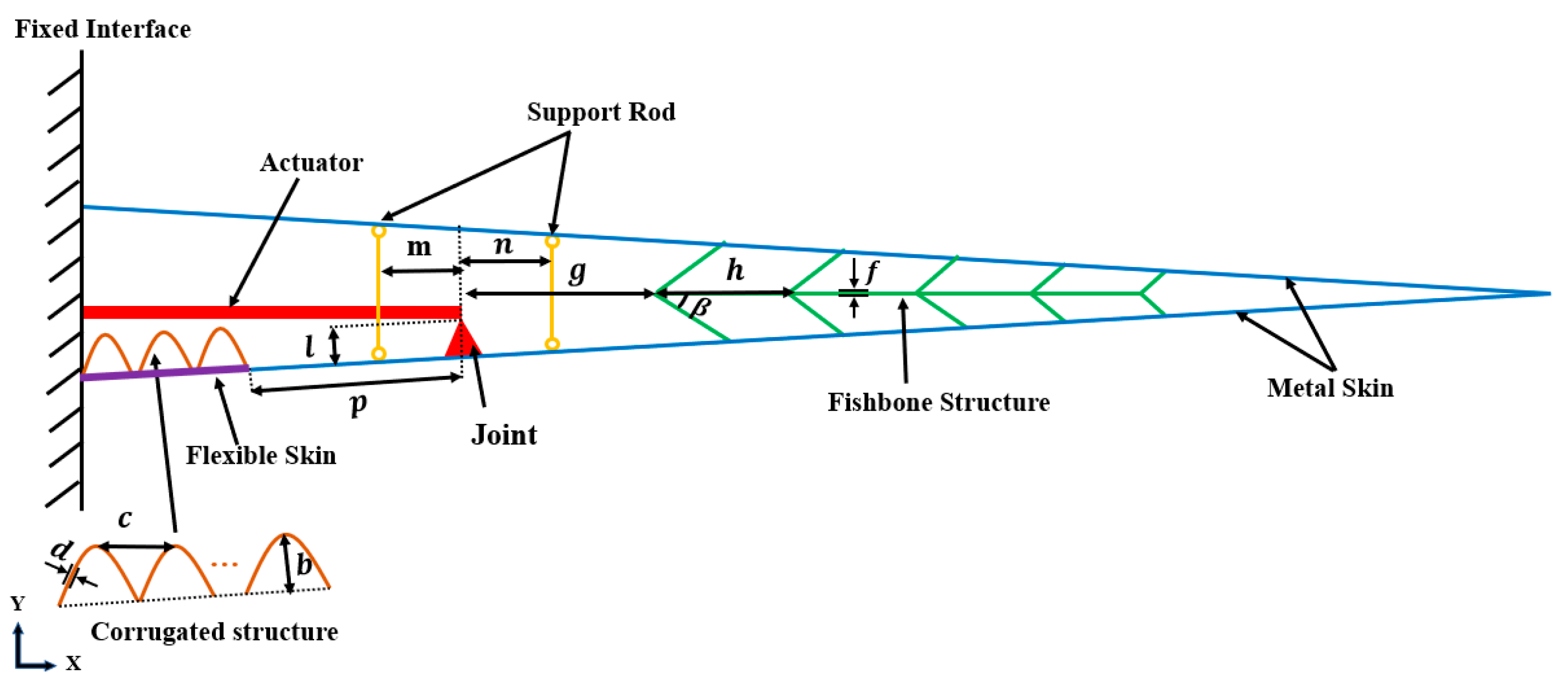
The structure of the morphing trailing edge consists of five structural component categories: skin (including flexible skin and metal skin), corrugated structure, actuator, fishbone structure, and support rods as shown in Figure 2. The actuator (red component) is an electric cylinder that can be elongated or shortened. When the actuator moves, the joint that is mounted on the lower airfoil close to the flexible skin will be pushed or pulled. The flexible skin (purple component) is located at the root of the lower skin, so as to accommodate the difference in the deformation of the upper and lower skins when the trailing edge becomes curved.
The flexible skin (purple component) is attached with the corrugated structure (brown component) on the inner side to increase its transverse load-bearing capacity. The corrugated structure consists of n 1 corrugations whose height, spacing and thickness are b, c, and d, respectively. To increase the load-bearing capacity and prevent local buckling of the metal skins upon bending, two support rods (yellow components) and a fishbone structure (green component) are mounted between the upper and lower skins to provide additional support between them.
The fishbone structure is located at a distance g from the joint. The fishbone structure is composed of n 2 V-shaped ribs connecting to a central beam. The angle between each V-rib and the beam is denoted as β, and the distance between two adjacent V-ribs is h. The material thickness of both the beam and the V-rib is f. The joint is positioned at a height l from the lower skin and a distance p from the flexible skin. The two support rods are located at the distance m and n measured from the joint, respectively. These support rods have a rectangular cross section of size q × r.

2.3. 3D Structural Layout

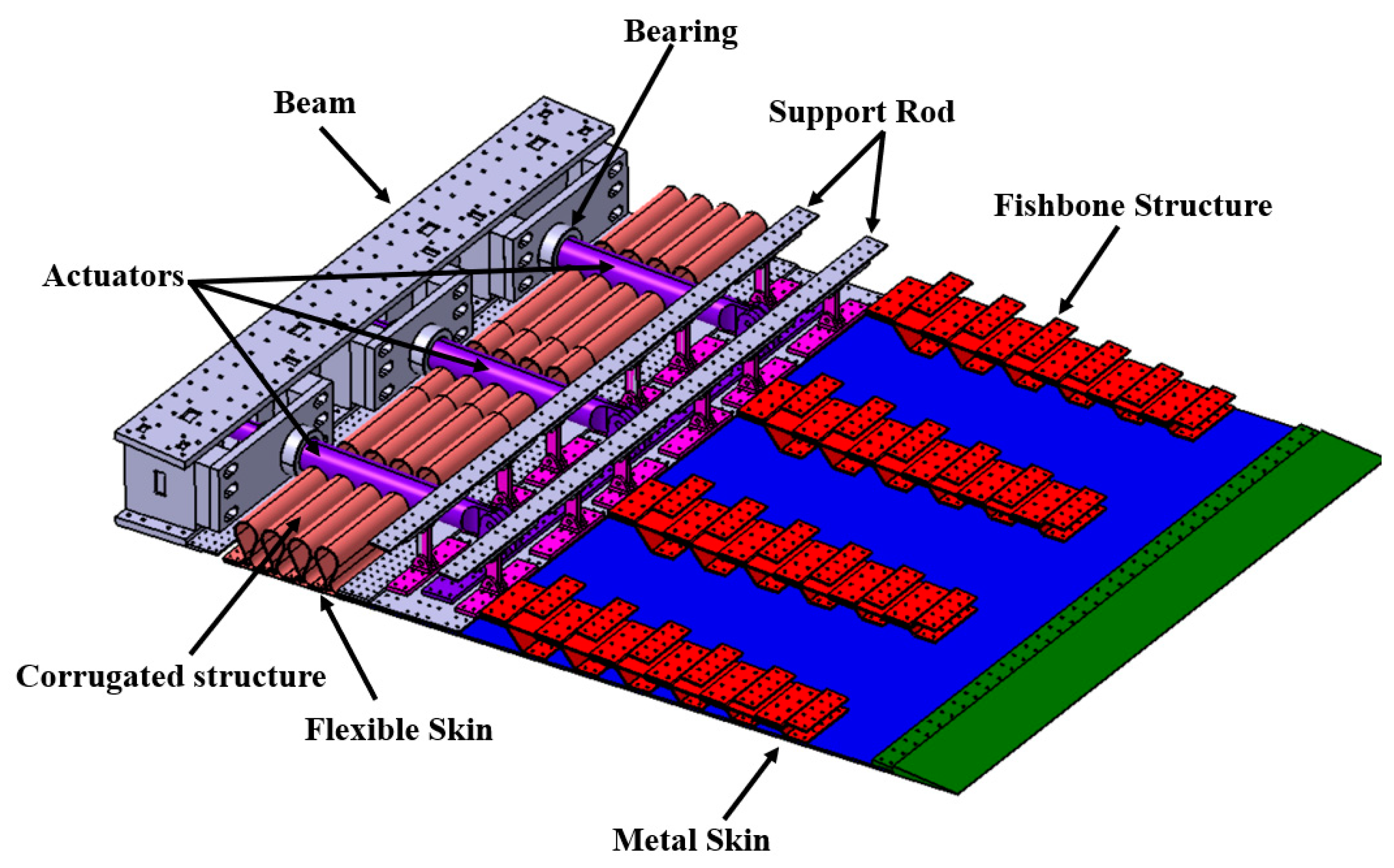
Based on the 2D layout, the 3D structure of the morphing trailing edge was designed, as shown in Figure 3. In this work, the size of the morphing trailing edge in the spanwise direction is taken as 1 m. If a large number of actuators are used, it will bring great challenges to the installation and synchronization of these actuators. On the other hand, if too few actuators are used, the size and weight of actuator will increase to generate the required driving force. Hence, three actuators with an appropriate size capable of generating the required driving forces are used. The actuators are fixed to the beam at the base, pass through the bearing, and pin-connected to the joint at the moving end.
The flexible skin is a two-layer stretchable structure consisting of a deformable metallic cellular structure and an elastic silicone rubber panel, as shown in Figure 4a. The cellular structure is designed to enable deformation of the structure in the in-plane direction, while increasing the stiffness in the out-of-plane direction. It consists of four deformable parts and five rigid parts, as shown in Figure 4b. Each individual deformable part consists of a number of circular arcs of radius 6.25 mm and double tangents to the arcs. The rigid part is the beam used to connect to the corrugated structure, as shown in Figure 4c. The silicone rubber is 2 mm thick, providing a surface seal. The corrugated structures are located inside of the flexible skin to increase the load-bearing capacity of the flexible skin, as shown in Figure 4a. The flat sections between the adjacent corrugations serve as the connection area to the flexible skin, as shown in Figure 4d. The flexible skin and the corrugated plate are connected to the metal skin on one side and to the fixed part at the base on the other side, by fastening to the lap plate. It is worth noting that the flexible skin and the corrugated structure need to be stretched to connect with the trailing edge in the non-deflected state.
If one continuous piece of fishbone structure is used in the spanwise direction, it will lead to excessive stiffness and weight. Herein, four fishbone structures with a width of 100 mm were utilized with a spacing of 200 mm between each set. As shown in Figure 3, six pairs of support rods are hinged on the trusses, which are fixed to the metal skins of the upper and lower airfoils.

3. Finite Element Simulation Studies and Parametric Design

3.1. Parametric Design of 2D Morphing Trailing Edge

The 2D finite element model of the trailing edge is established in the FE solver Abaqus/Explicit, as shown in Figure 5. The main structures of the model are built by the shell elements, and the spanwise width of the model is taken as 100 mm. The material of the ordinary metal skin and fishbone structure is aluminum alloy (E = 70 GPa, ν = 0.3); and that of the corrugated structure, support rod, and pivot is steel (E = 210 GPa, ν = 0.3). The element type of the metal skin, corrugated structure, fishbone structure, and pivot is S4R; and that of the support rod is B31. In this model, the fishbone structure and the metal skins, and the joint and the metal skin are connected by tie constraints. The nodes at both ends of the support rod are kinematically coupled with the nodes on the upper and lower skins with the rotational degrees of freedom set free. The boundary conditions constrain the translational and rotational dofs of the nodes of the upper airfoil and corrugated structure at the root. The 0.015 MPa aerodynamic load is applied perpendicularly to the upper airfoil.
Based on the above FE modelling process, simulations were carried out for structures with different parameters. The main design variables are shown in Table 1. The size and stiffness of the corrugated structure will have a significant impact on the deformation and load carrying performance of the flexible skin. In the analysis, the considered value ranges for the parameters of the corrugated structure are as follows: 3 to 5 for number of corrugates n 1 , 20–40 mm for spacing c , 60–80 mm for height b , and 1–2 mm for wall thickness d . When the aerodynamic load acts on the skin, the actuator will be subjected to an axial force and a bending moment relating to the height of the joint. The loads the actuator is subjected to depend largely on the location of the joint. The considered value ranges of the height l and the position p of the joint are 30–50 mm and 70–80 mm, respectively. The size and position of the fishbone is related to the stiffness of the part of the trailing edge to which it is attached, which affects the smoothness of the trailing edge airfoil and the load-carrying capacity of the trailing edge.The considered value ranges for the parameters of the fishbone structure are as follows: 4 to 6 for number of V-shaped ribs, 80–100 mm for spacing h , 150–160 mm for position g , 2–3 mm for thickness f , and 45°–50° for angle β. If the support rods are not properly positioned and sized, the trailing edge profile may be discordant and have a large local rate of curvature change. The considered value ranges of the position m, the position n are both 50 mm–60 mm, and the values of the considered section widths q and lengths r are 6–10 mm and 15–20 mm, respectively. The thickness s range of metal skins is considered to be 2–4 mm.
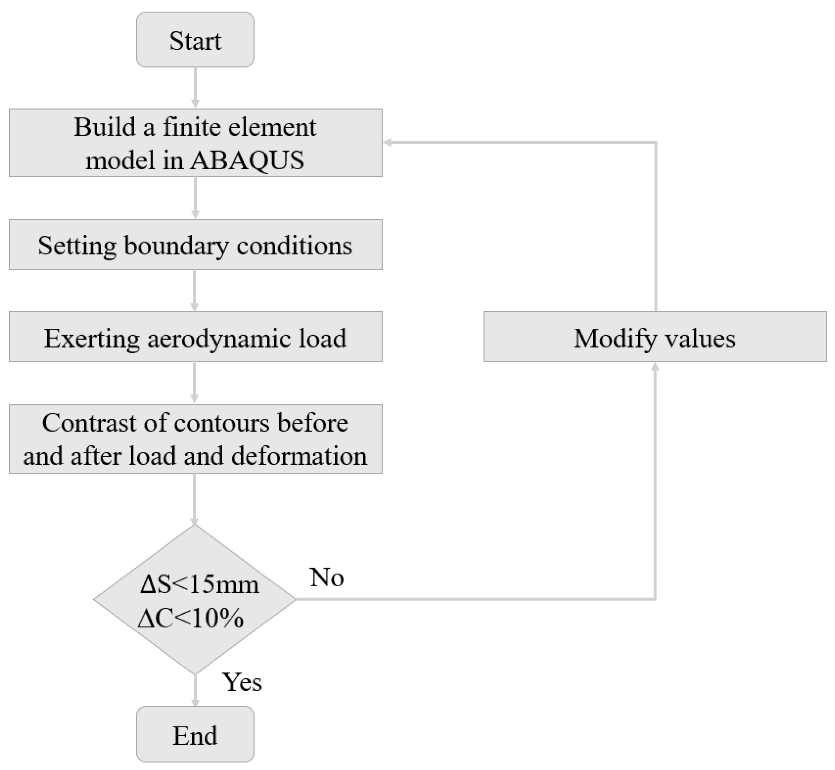
The value selection of different parameters depends on whether they can make the trailing edge structure achieve two design goals; i.e., the trailing edge can smoothly and continuously deflect up and down by 15° and it can bear a 0.015 MPa aerodynamic load. In order to evaluate whether these two design objectives are met, two parameters are defined in this paper: the maximum curvature change rate ∆C and the maximum deviation ∆S. In this work, ten equal points on the upper and lower airfoil are taken, and the rate of change of curvature at each of these ten points is calculated. ∆C is defined as the largest rate of change in curvature of these ten points. The displacement data of the node at tip of the trailing edge is extracted before and after load. ∆S is defined as the maximum deviation of this point. The design objectives are set as ∆C is less than 10% and ∆S is less than 15 mm. Figure 6 shows the process of parametric calculation of trailing edge structure. First of all, this work take intermediate values for all parameters and build finite element model in Abaqus/Explicit using this set of parameters. Second, the aerodynamic load is applied to the model and the solution for the loaded state is carried out. Then, the contours of the trailing edge before and after loading and deformation are compared and calculated; ∆C and ∆S for each state (loaded and unloaded) are calculated separately. If both ∆C and ∆S are within the design target, then this set of parameters is selected as the structural parameters for the trailing edge. Otherwise, modify values will be applied based on the approximation of the calculated results to the design target; and the model will be subsequently re-modeled, loaded, and calculated with the new parameters. Finally, the structure of the target was obtained, with Table 1 showing the selected parameters.
The results of FE analysis are shown in Figure 7. We can see the stress contour of the trailing edge in the non-deflected state, downward deflection state, and upward deflection state before and after applying the aerodynamic load. In the non-deflected state, Figure 7a shows that the displacement of the wing tip is 0.006 mm and Figure 7b shows that the displacement of the wing tip is also 0.006 mm after applying the aerodynamic load. In the downward deflection state, Figure 7c shows that the displacement of the wing tip is 319 mm and Figure 7d shows that the displacement of the wing tip is 315 mm after applying the aerodynamic load. In the upward deflection state, Figure 7e shows that the displacement of the wing tip is 310 mm and Figure 7f shows that the displacement of the wing tip is 314 mm after applying the aerodynamic load. The maximum curvature change rate ∆C of the 2D trailing edge is less than 5% and the maximum deviation ∆S of the 2D trailing edge is less than 5 mm. The results show that when the trailing edge of the wing is subjected to a 0.015 MPa aerodynamic load in the non-deflected state, upward deflection state, and downward deflection state, the structure can maintain its shape, which verifies the bearing capacity. In addition, the effect of camber morphing has a good quality. Values of reaction forces at the joint in different situations are shown in Table 2. Several conclusions can be drawn from these results. The value of no aerodynamic load in the non-deflected state represents the force required to drive the flexible skin. However, values in the downward deflection do not include the force driving the flexible skin. Values of upward deflection are inconsistent with that of downward deflection in two load modes, and the maximum value appears when the trailing edge in downward deflection is loaded, which is 7664 N. In addition, when the trailing edge is in upward deflection, the value under load is smaller than that under no load.

3.2. Finite Element Simulation Studies of the 3D Morphing Trailing Edge

The performance of the 3D trailing edge design is verified by FE simulation in this paper, as shown in Figure 8. The main parameters of the model are described in Section 2.3 and Section 3.1. The FE analysis of the 3D model is performed in Abaqus/Explicit. Because the driving force of the flexible skin is much smaller as compared to that of the corrugated structure, only the corrugated structure is modelled in the 3D model for simplicity. The element type of the main structure is C3D8R and that of the drive rod is C3D4. The material of the metal skin, connection block, and fishbone structure are aluminum alloy (E = 70 GPa, ν = 0.3); and that of the other structures is steel (E = 210 GPa, ν = 0.3). The fishbone structure and skin, skin, and joint are connected together by tie constraints. The beam and bearings are fixed, and the hard contact interaction is defined between the bearing and the actuator rod. An initial displacement is applied to the end of the corrugated structure to simulate the installation status in the non-deflected state of the trailing edge. Then, different horizontal displacement constraints are applied to the end of the actuator rod to simulate the actuation of the trailing edge: 0 mm for the non-deflected state, −35 mm for the downward deflection state, and 35 mm for the upward deflection state. Furthermore, the aerodynamic load of 0.015 MPa is applied to the lower metal skin of the trailing edge in the three states. The boundary conditions constrain the degrees of freedom of movement and rotation of the beam at the fixed interface. The aerodynamic loading of 0.015 MPa was applied perpendicularly to the upper airfoil.
The detailed FE model for the flexible and the corrugated structure alone was also established to evaluate the load-bearing capacity of the flexible skin, as shown in Figure 8b. The element type of flexible skin and corrugated structure is C3D8R. The material of cellular skin is aluminum alloy (E = 70 GPa, ν = 0.3), and the material of corrugated structure is steel (E = 210 GPa, ν = 0.3). Five connection areas of cellular structure are connected to the corrugated structure by tie constraints. One end of the flexible skin is fixed, and the displacement boundary condition is applied to the other end. The aerodynamic loading of 1500 kg/ m 2 was applied to the cellular structure to examine the bearing capacity of flexible skin.
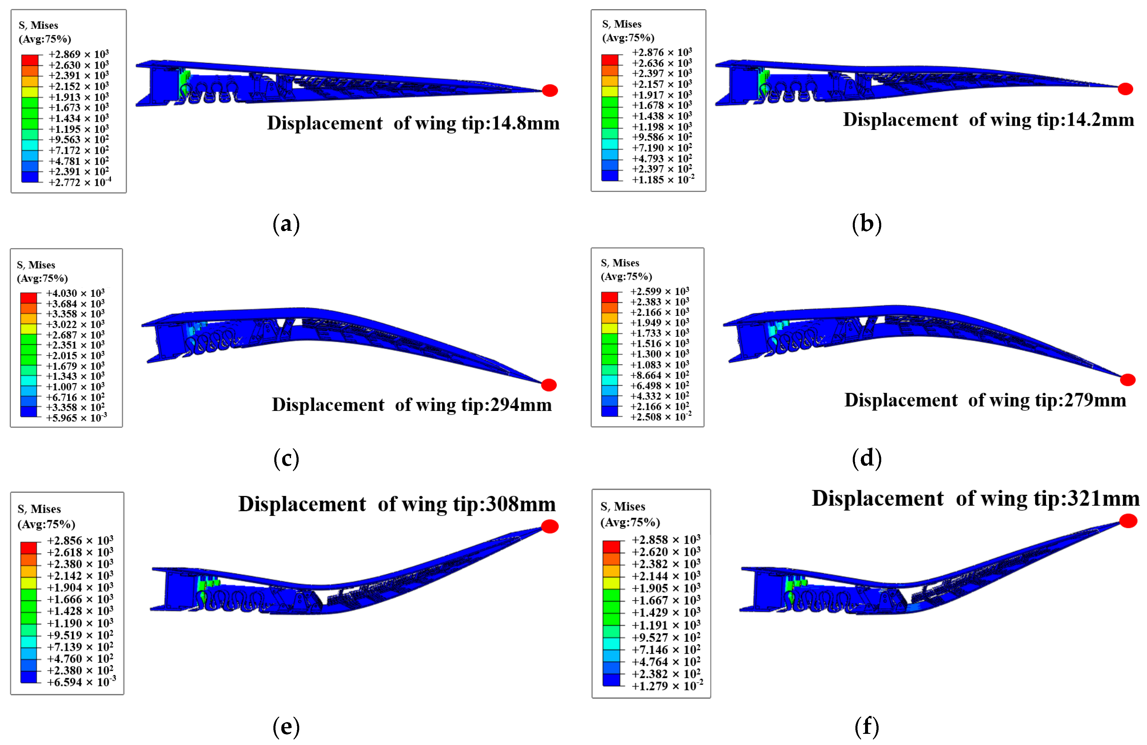
Figure 9 shows the FE analysis results of the 3D morphing trailing edge. We can see the stress contour of the trailing edge in the non-deflected state, downward deflection state, and upward deflection state before and after applying the aerodynamic load. In the non-deflected state, Figure 9a shows that the displacement of the wing tip is 14.8 mm and Figure 9b shows that the displacement of the wing tip is 14.2 mm after applying the aerodynamic load. In the downward deflection state, Figure 9c shows that the displacement of the wing tip is 294 mm and Figure 9d shows that the displacement of the wing tip is 279 mm after applying the aerodynamic load. In addition, in the upward deflection state, Figure 9e shows that the displacement of the wing tip is 308 mm and Figure 9f shows that the displacement of the wing tip is 321 mm after applying the aerodynamic load. The results show that when the trailing edge is subjected to a 0.015 MPa aerodynamic load in the non-deflected state, upward deflection state, and downward deflection state, trailing edge has good deformation quality and bearing capacity. The curvature change rate ∆C of the 3D trailing edge is 6% and the maximum deviation ∆S of the 3D trailing edge is less than 15 mm. The contour of the trailing edge before and after morphing is basically consistent with that in the 2D analysis, indicating that the design of our 3D layout is feasible.
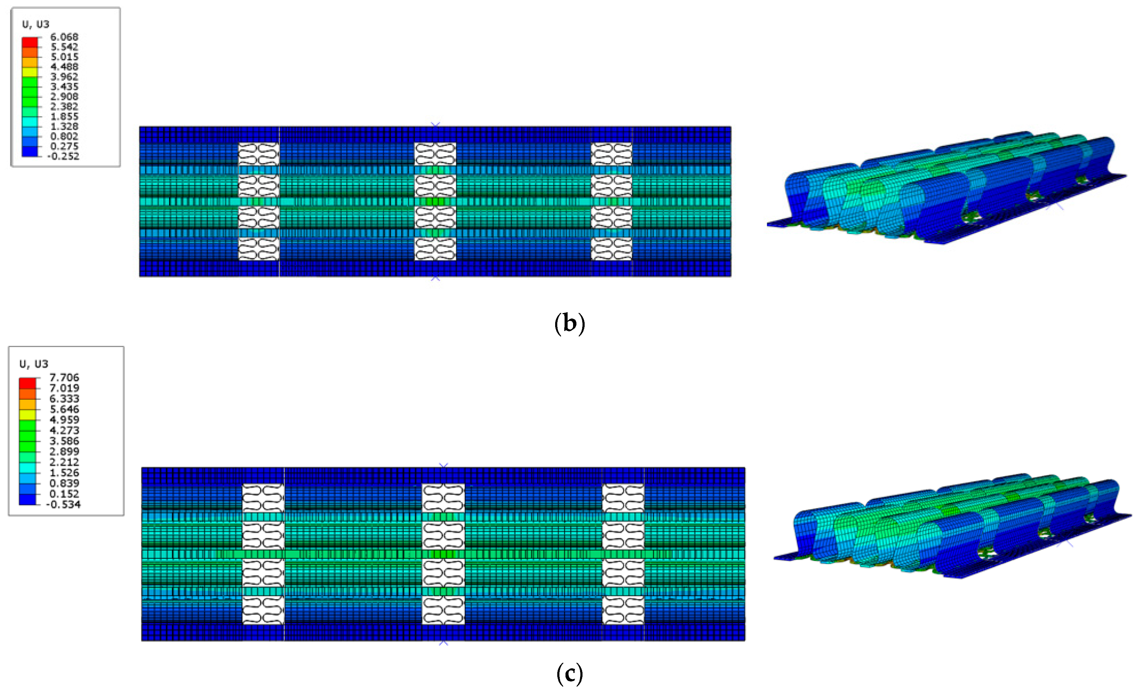
The FE results of the flexible skin are shown as Figure 10. When bearing a 0.015 MPa load in the non-deflected state, the normal displacement of the flexible skin is 4.215 mm, which is shown in Figure 10a. When the flexible skin is stretched to 35 mm, the required driving force is 9733 N. After the flexible skin is stretched to 35 mm, a 0.015 MPa aerodynamic load is exerted on the flexible skin. The normal displacement of the whole structure is 6.068 mm, which is shown in Figure 10b. When the flexible skin is stretched to 70 mm, the required driving force is 19,330 N. After the flexible skin is stretched to 70 mm, a 0.015 MPa aerodynamic load is exerted on the flexible skin. The normal displacement of the whole structure is 7.706 mm, which is shown in Figure 10c. In summary, the flexible skin not only meets the deformation requirements, but also meets the load-bearing requirements. The normal displacement mainly occurs in the cellular structure’s middle area that is not connected to the corrugated structure.

4. Manufacturing and Testing

4.1. Assembly and Integration

The cellular structure is made by 3D printing, whose material is AlSi10Mg aluminum alloy. The corrugated structure is made of 65Mn spring steel, which is produced by wire cutting. The V-ribs and the beam of fishbone structure are made of 45 steel by a laser-cutting process, and then bolted together. The support rods and joints are fabricated from 45 steel by lathe. The material used for the metal skin is an aluminum alloy sheet, which is made by laser cutting.
During the assembly process, the metal skins first are connected with four fishbone structures. Secondly, the support rods and joint were installed on the metal skins. Then, the actuator was fixed to the beam at the base and attached to the joint. After attaching the deformation skin and corrugated structure with rivets, they are riveted to the beam at the base and metal skin of the lower airfoil using lap plates, at which point the actuator retracts to deflect the trailing edge downward. Finally, we adjust the length of the actuator until the trailing edge is in a non-deflected state, and attach the rigid skin of the upper airfoil to the beam at the base. The assembled prototype of morphing trailing edge is shown in Figure 11.

4.2. Deformation Testing and Load Testing

In this work, the prototype was used for the deformation test and loading test. The electric cylinder mounting bracket at the end of the prototype is fixed on the connecting frame installed on the loading pedestal, and the loading pedestal is fixed on the ground by bolts. The deformation test involves setting the position of the actuator rod to 0 and the speed is 5 mm/s in the non-deflected state of the trailing edge. By inputting the required upward deflection and downward deflection displacement values in the controller, the actuator rod will move to deform the trailing edge accordingly. The trailing edge completes one action cycle (horizontal state–upward deflection 15°; horizontal state–downward deflection 15°, horizontal state) in 25 s in the process of the deformation test.
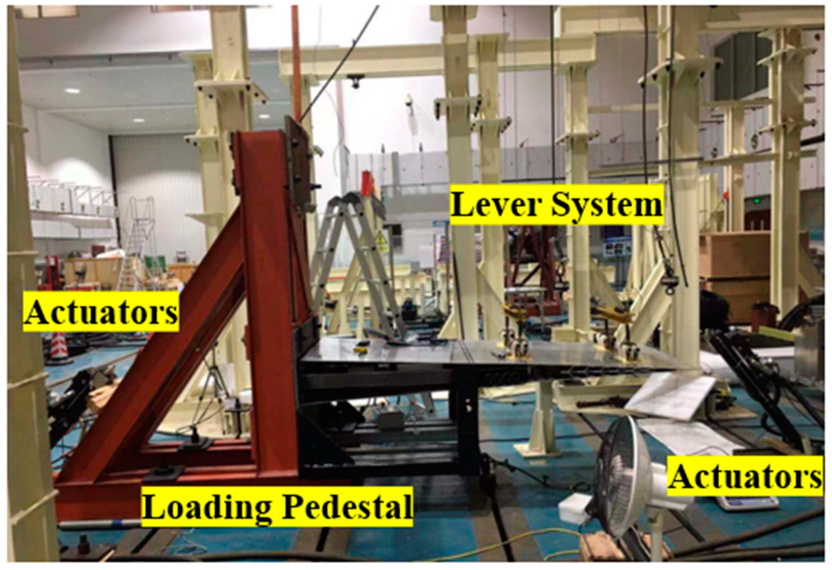
Figure 12 shows the configuration settings of the load testing. In the static load test of the trailing edge, the distributed aerodynamic load was equivalently converted to a finite number of nodes. These nodes serve as loading points and are attached with adhesive tape to connect the trailing edge with the loading system. Two loading points are connected by levers, and then the position of the resultant force on the lever is obtained according to the balance of moment, so that the two loading points can achieve synchronous loading. In this way, the upper skin was divided into four regions, and the center of each region was taken as the loading point. After the lever system is linked to the trailing edge, the rope is connected to the actuator through a pulley, which is fixed to the experimental framework. The experimental steps are as follows: firstly, building the experimental framework based on the size of the trailing edge. Then, pasting the adhesive tape on the upper skin of the trailing edge. Actuators load up to 0.015 MPa, with ten percent of the target load as a step. A graduated scale on one side of the wingtip at the trailing edge enables the wingtip displacement to be directly measured during the test.
Figure 13a shows the different states of the trailing edge at different times in the deformation test. Meanwhile, Figure 13b shows the finite element calculation results under the corresponding conditions. The wingtip deflection and wingtip angle α at different times in the deformation test, and the corresponding 3D finite element simulation results are shown in Table 3. It is obvious that the test and simulation results basically match.
During the test, the situation of the trailing edge was monitored and the deformation of the trailing edge was compared with the finite element analysis results in real time. Figure 14 shows the static load test result of the trailing edge under a 0.015 MPa aerodynamic load. The displacement of the wingtip is 14.9 mm measured by the loading test, and the displacement of the wingtip is 14.2 mm measured by the simulation. The test results show that the trailing edge can bear the aerodynamic load of 0.015 MPa, which is consistent with the finite element analysis results.

5. Conclusions

In this paper, a seamless surface morphing trailing edge with flexible skin is designed, and parametric analysis and finite element calculation are conducted. Finally, a prototype is designed and deformation and load tests are performed. The main achievements of this paper include:
  • A seamless camber morphing trailing edge with flexible skin is designed based on the local deformation principle;
  • The position and size of key structures are determined by parametric analysis and verified by finite element analysis of a 3D model;
  • A prototype is designed and manufactured, and a deformation test and load test are conducted. The test results show that the prototype can achieve 15° deflection and bear a 0.015 MPa aerodynamic load.
Further studies are planned to reduce the structural weight and driving force; and follow up to enhance the technical maturity of this programme with the aim of achieving flight experiments. This work will be helpful for the design and application of the morphing trailing edge and more related work in the future.

Author Contributions

Conceptualization, X.Z., J.Y. and N.C.; simulation and experiment, G.C. and T.M.; writing—original draft preparation, G.C. and T.M.; writing—review and editing, X.Z., J.Y. and N.C.; supervision, X.Z.; project administration, X.Z., J.Y. and N.C.; funding acquisition, X.Z. All authors have read and agreed to the published version of the manuscript.

Funding

This research was funded by the Aeronautical Science Foundation of China (grant no. 2019ZA57).

Data Availability Statement

Not applicable.

Conflicts of Interest

The authors declare no conflict of interest.

References

  1. Sofia, A.Y.N.; Meguid, S.A.; Tan, K.T.; Yeo, W.K. Shape morphing of aircraft wing: Status and challenges. Mater. Des. 2010, 31, 1284–1292. [Google Scholar]
  2. Oliviu, S.G.; Andreea, K.; Mihaela, B.R. Optimization of an Unmanned Aerial System’ Wing Using a Flexible Skin Morphing Wing. Sae Int. J. Aerosp. 2013, 2013, 115–121. [Google Scholar]
  3. Gu, X.; Yang, K.-K.; Wu, M.; Zhang, Y. Integrated optimization design of smart morphing wing for accurate shape control. Chin. J. Aeronaut. 2021, 34, 135–147. [Google Scholar] [CrossRef]
  4. Previtali, F.; Arrieta, A.F.; Ermanni, P. Performance of a three-dimensional morphing wing and comparison with a conventional wing. AIAA J. 2014, 52, 2101–2113. [Google Scholar] [CrossRef]
  5. Li, D.; Zhao, S.; Da Ronch, A.; Xiang, J.; Drofelnik, J.; Li, Y.; Zhang, L.; Wu, Y.; Kintscher, M.; Monner, H.P.; et al. A review of modelling and analysis of morphing wings. Prog. Aerosp. Sci. 2018, 100, 46–62. [Google Scholar] [CrossRef] [Green Version]
  6. De Gaspari, A.; Ricci, S. A two-level approach for the optimal design of morphing wings based on compliant structures. J. Intell. Mater. Syst. Struct. 2011, 22, 1091–1111. [Google Scholar] [CrossRef]
  7. Monner, H.P.; Breitbach, E.; Bein, T.; Hanselka, H. Design aspects of the adaptive wing—The elastic trailing edge and the local spoiler bump. Aeronaut. J. 2000, 104, 89–95. [Google Scholar] [CrossRef]
  8. Monner, H.P. Realization of an optimized wing camber by using formvariable flap structures. Aerosp. Sci. Technol. 2001, 5, 445–455. [Google Scholar] [CrossRef]
  9. Icardi, U.; Ferrero, L. SMA actuated mechanism for an adaptive wing. J. Aerosp. Eng. 2011, 24, 140–143. [Google Scholar] [CrossRef]
  10. Meguid, S.A.; Su, Y.; Wang, Y. Complete morphing wing design using flexible-rib system. Int. J. Mech. Mater. Des. 2017, 13, 159–171. [Google Scholar] [CrossRef]
  11. Arena, M.; Nagel, C.; Pecora, R.; Schorsch, O.; Concilio, A.; Dimino, I. Static and Dynamic Performance of a Morphing Trailing Edge Concept with High-Damping Elastomeric Skin. Aerospace 2019, 6, 22. [Google Scholar] [CrossRef] [Green Version]
  12. Bartley-Cho, J.D.; Wang, D.P.; Martin, C.A.; Kudva, J.N.; West, M.N. Development of High-rate, Adaptive Trailing Edge Control Surface for the Smart Wing Phase 2 Wind Tunnel Model. J. Intell. Mater. Syst. Struct. 2004, 15, 279–291. [Google Scholar] [CrossRef]
  13. Moored, K.W.; Bart-Smith, H. The analysis of tensegrity structures for the design of a morphing wing. J. Appl. Mech. 2007, 74, 668–676. [Google Scholar] [CrossRef]
  14. Woods BK, S.; Bilgen, O.; Friswell, M.I. Wind tunnel testing of the fish bone active camber morphing concept. J. Intell. Mater. Syst. Struct. 2014, 25, 772–785. [Google Scholar] [CrossRef]
  15. Woods BK, S.; Dayyani, I.; Friswell, M.I. Fluid/structure-interaction analysis of the fish-bone-active-camber morphing concept. J. Aircr. 2015, 52, 307–319. [Google Scholar] [CrossRef] [Green Version]
  16. Kumar, D.; Ali, S.F.; Arockiarajan, A. Structural and Aerodynamics Studies on Various Wing Configurations for Morphing. IFAC-Pap. 2018, 51, 498–503. [Google Scholar] [CrossRef]
  17. Wu, R.; Soutis, C.; Zhong, S.; Filippone, A. A morphing aerofoil with highly controllable aerodynamic performance. Aeronaut. J. 2017, 121, 54–72. [Google Scholar] [CrossRef] [Green Version]
  18. Wu, R.; Sun, J.; Chang, Z.; Bai, R.; Leng, J. Elastic composite skin for a pure shear morphing wing structures. J. Intell. Mater. Syst. Struct. 2015, 26, 352–363. [Google Scholar] [CrossRef] [Green Version]
  19. Alsaidi, B.; Joe, W.Y.; Akbar, M. Computational analysis of 3D lattice structures for skin in real-scale camber morphing aircraft. Aerospace 2019, 6, 79. [Google Scholar] [CrossRef] [Green Version]
  20. Mukherjee, A.; Ali, S.F.; Arockiarajan, A. Modeling of integrated shape memory alloy and Macro-Fiber Composite actuated trailing edge. Smart Mater. Struct. 2020, 29, 085005. [Google Scholar] [CrossRef]
  21. Elsheikh, M.E. Highly Flexible Wind Turbine Blades Utilizing Corrugated Surface Hinges. Coatings 2021, 11, 635. [Google Scholar] [CrossRef]
  22. Ghabezi, P. Rectangular and triangular corrugated composite skins. Fibers Polym. 2018, 19, 435–445. [Google Scholar] [CrossRef]
  23. Ghabezi, P.; Mohammad, G. Mechanical Behavior of Quasi-sinusoidal Corrugated Composite sheets. Iran. J. Polym. Sci. Technol. 2012, 24, 379–389. [Google Scholar]
  24. Dimino, I.; Flauto, D.; Diodati, G.; Concilio, A.; Pecora, R. Actuation system design for a morphing wing trailing edge. Recent Pat. Mech. Eng. 2014, 7, 138–148. [Google Scholar] [CrossRef] [Green Version]
  25. Liu, S.; Ge, W.; Li, S. Optimal Design of Compliant Trailing Edge for Shape Changing. Chin. J. Aeronaut. 2008, 21, 187–192. [Google Scholar]
  26. Campanile, L.F.; Sachau, D. The belt-rib concept: A structronic approach to variable camber. J. Intell. Mater. Syst. Struct. 2000, 11, 215–224. [Google Scholar] [CrossRef]
  27. Barbarino, S.; Bilgen, O.; Ajaj, R.M.; Friswell, M.I. A review of morphing aircraft. J. Intell. Mater. Syst. Struct. 2011, 22, 823–877. [Google Scholar] [CrossRef]
  28. Dayyani, I.; Shaw, A.D.; Flores, E.S.; Friswell, M.I. The mechanics of composite corrugated structures: A review with applications in morphing aircraft. Compos. Struct. 2015, 133, 358–380. [Google Scholar] [CrossRef] [Green Version]
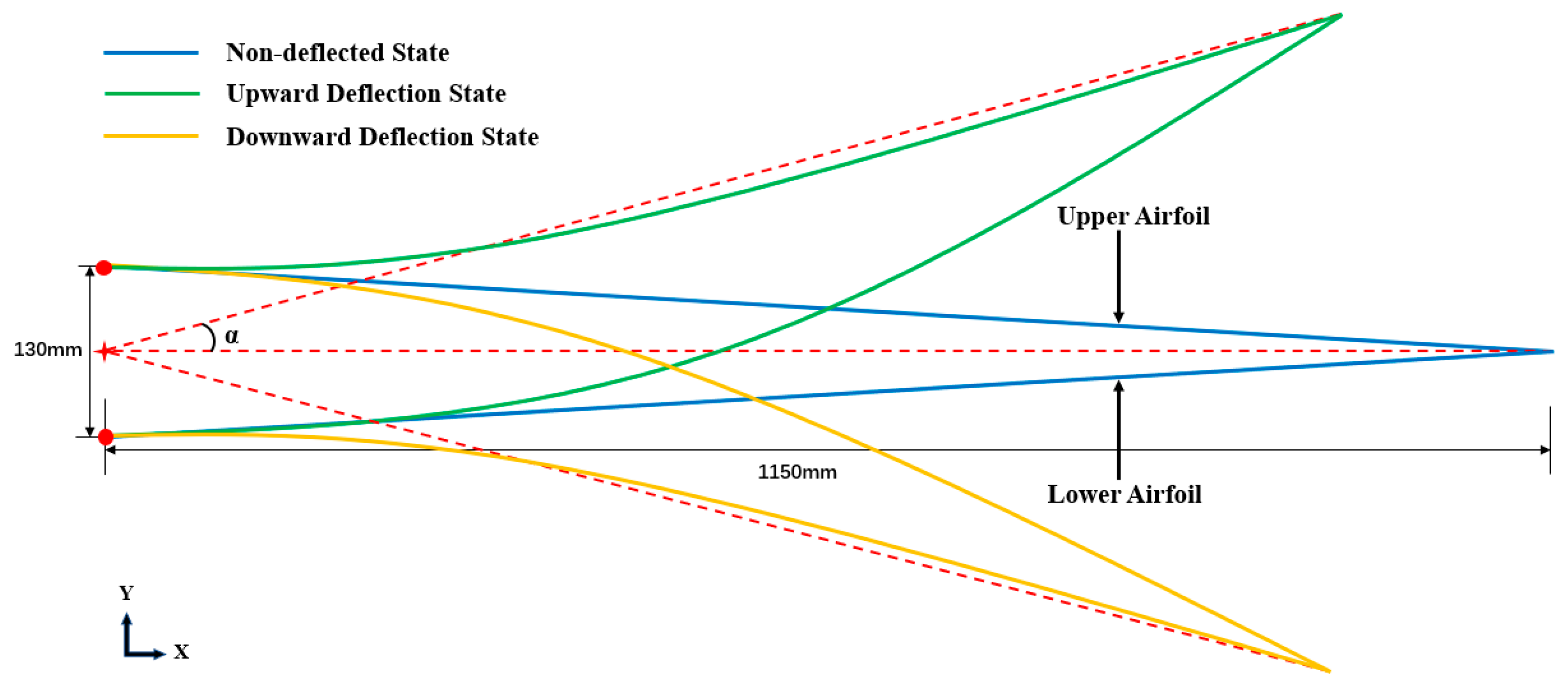
Figure 1. The initial profile and deformation target of the trailing edge.
Aerospace 10 00282 g001
Figure 2. The 2D structural layout of the trailing edge.
Aerospace 10 00282 g002
Figure 3. The 3D structural layout of the trailing edge.
Aerospace 10 00282 g003
Figure 4. Structure and connection of flexible skin: (a) side view of the flexible skin; (b) internal structure and size of the cellular structure; (c) distribution and size of corrugated structures and flexible skins in the direction of spanwise; (d) connection of flexible skins, corrugated structures, and metal skins.
Aerospace 10 00282 g004aAerospace 10 00282 g004b
Figure 5. The finite element model of 2D trailing edge.
Aerospace 10 00282 g005
Figure 6. Flow of parametric calculation of trailing edge structure.
Aerospace 10 00282 g006
Figure 7. Stress contour and the displacement of wing tip of the selected 2D trailing edge: (a) without aerodynamic loads in the non-deflected state; (b) with aerodynamic loads in the non-deflected state; (c) without aerodynamic loads in downward deflection; (d) with aerodynamic loads in downward deflection; (e) without aerodynamic loads in upward deflection; (f) with aerodynamic loads in upward deflection.
Aerospace 10 00282 g007
Figure 8. The 3D finite element model. (a) 3D trailing edge without flexible skin; (b) flexible skin and corrugated structure.
Aerospace 10 00282 g008
Figure 9. Stress contour and the displacement of wing tip of the selected 3D trailing edge: (a) without aerodynamic loads in the non-deflected state; (b) with aerodynamic loads in the non-deflected state; (c) without aerodynamic loads in downward deflection; (d) with aerodynamic loads in downward deflection; (e) without aerodynamic loads in upward deflection; (f) with aerodynamic loads in upward deflection.
Aerospace 10 00282 g009
Figure 10. Deformation contour of the flexible skin bearing a 0.015 MPa load: (a) when the flexible skin is not stretched; (b) when the flexible skin was stretched for 35 mm; (c) when the flexible skin was stretched for 70 mm.
Aerospace 10 00282 g010aAerospace 10 00282 g010b
Figure 11. The trailing edge physical prototype and main parts.
Aerospace 10 00282 g011
Figure 12. The configuration settings of the load testing.
Aerospace 10 00282 g012
Figure 13. Trailing edge during active deformation: (a) in the deformation test; (b) in finite element simulation.
Aerospace 10 00282 g013
Figure 14. The trailing edge in loading test.
Aerospace 10 00282 g014
Table 1. Range of selected parameters and results for parametric calculation of trailing edge structure.
ParameterValue RangeSelected Parameters
n 1 3~54
b 60~80 mm70 mm
c 20~40 mm30 mm
d 1~2 mm2 mm
l 30~50 mm40 mm
p 70~80 mm74 mm
n 2 4~66
h 80~100 mm90 mm
g 150~160 mm154 mm
f 2~3 mm3 mm
β 45°~50°50°
m 50 mm~60 mm55.7 mm
n 50 mm~60 mm57 mm
q r 6~10 mm ∗ 15~20 mm8 mm ∗ 18 mm
s 3~5 mm4 mm
Table 2. Values of reaction forces at the joint in different situations.
StateValue
without aerodynamic loads in the non-deflected state1070 N
with aerodynamic loads in the non-deflected state3723 N
without aerodynamic loads in upward deflection−4863 N
with aerodynamic loads in upward deflection−1020 N
without aerodynamic loads in downward deflection2330 N
with aerodynamic loads in downward deflection7664 N
Table 3. The wingtip deflection and wingtip angle, and the deflection angle α of deformation test and 3D finite element simulation.
TimeThe Wing Tip
Deflection
in Experiment
The Wing Tip
Deflection
in Simulation
The Deflection
Angle α
in Experiment
The Deflection
Angle α
in Simulation
0 s14 mm14.8 mm
6.5 s307 mm308 mm15°15°
15 s14 mm14.8 mm
20 s294 mm294 mm−15°−15°
25 s14 mm14.8 mm
Disclaimer/Publisher’s Note: The statements, opinions and data contained in all publications are solely those of the individual author(s) and contributor(s) and not of MDPI and/or the editor(s). MDPI and/or the editor(s) disclaim responsibility for any injury to people or property resulting from any ideas, methods, instructions or products referred to in the content.