Review

Manufacturing Technology of Lightweight Fiber-Reinforced Composite Structures in Aerospace: Current Situation and toward Intellectualization

1
School of Aerospace Engineering and Applied Mechanics, Tongji University, Shanghai 200092, China
2
Composites Center, COMAC Shanghai Aircraft Manufacturing Co., Ltd., Shanghai 201324, China
*
Authors to whom correspondence should be addressed.
Aerospace 2023, 10(3), 206; https://doi.org/10.3390/aerospace10030206
Submission received: 16 January 2023 / Revised: 11 February 2023 / Accepted: 14 February 2023 / Published: 22 February 2023

Abstract

:
Lightweight fiber-reinforced composite structures have been applied in aerospace for decades. Their mechanical properties are crucial for the safety of aircraft and mainly depend on manufacturing technologies such as autoclave, resin transfer molding and automated layup technology. In recent years, the rapid development of intelligent technology such as big data, deep learning, and machine learning has encouraged the development of manufacturing technologies to become low-cost, automatic, and intelligent. However, the current situation and intellectualization of manufacturing technologies is not well summarized. This paper reviews the advances in manufacturing technologies for fiber-reinforced composite structures, including autoclave, out of autoclave, resin transfer molding technologies, automated layup technology and additive manufacturing technology. Then, these technologies are compared in advantages and disadvantages, and their intellectualization development and challenges are also discussed. Finally, the development trend of intelligent manufacturing technologies and intelligent composite structures are discussed. This work can provide a reference for researchers in the related filed.

1. Introduction

Lightweight fiber-reinforced polymer (FRP) composite structures have been widely used in the aerospace industry due to their high strength-weight ratio, high temperature resistance, flexibility in design of different structures according to different property requirements and the ability to integrate large-scale integral components [1,2,3,4,5]. Demand for these lightweight FRP composites in aircraft is increasing sharply. At present, 50% composites are used in the Boeing 787, and 52% in the Airbus A350 [6], which are the most advanced civilian airplanes in the world. The use of FRP composites has reduced aircraft weight significantly, which makes aircraft more energy-efficient and improves economic benefits [6]. Moreover, with the development of low-cost manufacturing technologies of FRP composites, production costs have also dropped significantly. In a word, the extensive usage of FRP composites in aircraft has a positive effect on aircraft safety, economy, and environment, and the percentage of composite usage has become one of the indicators of aircraft advancement.
Compared to staple fiber, continuous fiber-reinforced composites are more widely used in aerospace because of their greater mechanical properties. The design process is the basis of FRP composite production; it includes the material selection and the determination of material content, and the internal structure of composites and so on, which decide the ideal mechanical properties of FRP composites. Therefore, the basis of designing FRP composites is figuring out the relationship between their ideal mechanical properties and these parameters. On the other hand, composite manufacturing techniques have remarkably evolved in recent decades, following two main goals: improving the manufacturing quality of composite components, and enhancing manufacturing efficiency [7]. The manufacturing quality decides their practical mechanical properties. In this paper, we focus on the manufacturing technologies of continuous fiber-reinforced composite structures for aerospace, because these technologies are crucial for producing composite structures with high performance.
The manufacturing process is crucial in order to achieve the desired performance of composites. Generally, this process includes the prefabricating and curing processes of composite structures (Figure 1). There are two paths to prefabricate components: dry fiber tows are laid up to construct dry preforms, and then resin is injected into the preforms to complete preforming, such as in resin transfer molding (RTM) [8]; the other path is to infiltrate the fibers with resin firstly to make prepreg, and then lay this up to form preforms, for instance, through automated layup technology (ALT) [9], which is increasingly used in aerospace.
The hand layup process is the conventional manufacturing method wherein fabric and resin are manually laid up layer by layer onto a mold surface to form a preform. This process has low equipment requirements but is labor-cost heavy and inefficient. Additionally, the products often have many voids, wrinkles and other defects, resulting in a lower performance than that of the designed object, so the hand layup process has been gradually declining in popularity in aerospace. To improve production efficiency and reduce defects in composite structures, computer and machine-aided ALT was presented to speed up the layup process (Figure 1a). ALT includes automated filament winding (AFW) [10,11], automated tape layup (ATL) [12] and automated fiber placement (AFP) [13]. In these layup methods, a layup head can wind or lay dry tapes/fibers or prepregs on a mold along the pre-planned path to make preforms (Figure 1c). Nowadays, ALT with in situ consolidation for thermoplastic FRP composites has been developed to reduce time consumption, since composites can be cured without other curing processes in autoclave or OoA [14].
In some cases, dry fibers are infiltrated with resin before the layup process, wherein the prepreg should be saved in a specific environment. However, in the liquid composite molding (LCM) method [15], resin infiltrates fibers after the layup process inside vacuum bags and molds (Figure 1b). Under the introduction of a vacuum or high pressure, composites have few voids and better performance than those produced by hand layup.
The curing of preforms is a key process of manufacturing excellent composite structures. Autoclave technology is currently the most mature and widely used curing approach, and has been adopted to fabricate many aircraft composite components (Figure 1d). High temperature and pressure in the autoclave can help the forming of components with high performance. However, maintaining a high temperature and pressure environment for a long time requires a lot of energy, which is one of the main reasons for high cost of autoclaves. Furthermore, the autoclave size limits the scale of components, and the manufacturing cost of the autoclave will rise as its size increases. For this reason, out of autoclave (OoA) [16], a low-cost manufacturing technology, was proposed, wherein composites are cured outside the autoclave (Figure 1d). The curing process is completed inside vacuum bags and molds under vacuum or higher pressure and a certain temperature environment. Since OoA does not require an autoclave, its cost is much lower, and the component size just depends on the mold. The first OoA-manufactured lightweight composite wing for a commercial aircraft, MC-21, has been developed by Russia, and MC-21 has completed its first fly in 2017. The manufacturing cost of the wing is only one-seventh of that produced by autoclave technology [17].
In the manufacturing technologies mentioned above, the forming process and curing process of composite structures are separated due to the thermal properties of thermoset resin. In fact, the two processes can be conducted simultaneously for thermoplastic composite structures. Earlier thermoplastic composites had poor performance and were not used widely. The flow of thermoplastics in fiber beds is quite difficult and requires higher processing temperature and pressure to ensure satisfactory fiber wetting [18]. Nowadays, the discovery of high-performance thermoplastic resin has helped to significantly improve the performance of thermoplastic composites; therefore, thermoplastic composites have regained researchers’ interest. By combining thermoplastic composites with ALT and addition manufacturing technology [19], researchers have developed in situ consolidation technology, wherein prepreg layup and resin consolidation are conducted simultaneously (Figure 1e). The proposed in situ consolidation technology improves both lay-up and curing efficiency, with a significant decrease in both time and economic costs. It has great potential to become one of the major composite manufacturing technologies.
With the rapid development of intelligent technology, digital and intelligent manufacturing technology has been an inevitable development trend [19]. Researchers have made some progress in this field. In particular, machine learning and neural network has been widely adopted to build a model to predict the complex relationships between various processing parameters, or even to control the parameters in those manufacturing technologies [20,21,22,23,24]. However, an overall review is still lacking. This paper presents a review of manufacturing technologies for continuous fiber-reinforced polymer composites. The composite manufacturing techniques, including autoclave, OoA, and RTM, and particularly ALT and additive manufacturing technology, are reviewed. Research focusing on the difficult issues of the processes is introduced and discussed. Finally, the intellectualization development trend of composite manufacturing technologies is predicted.

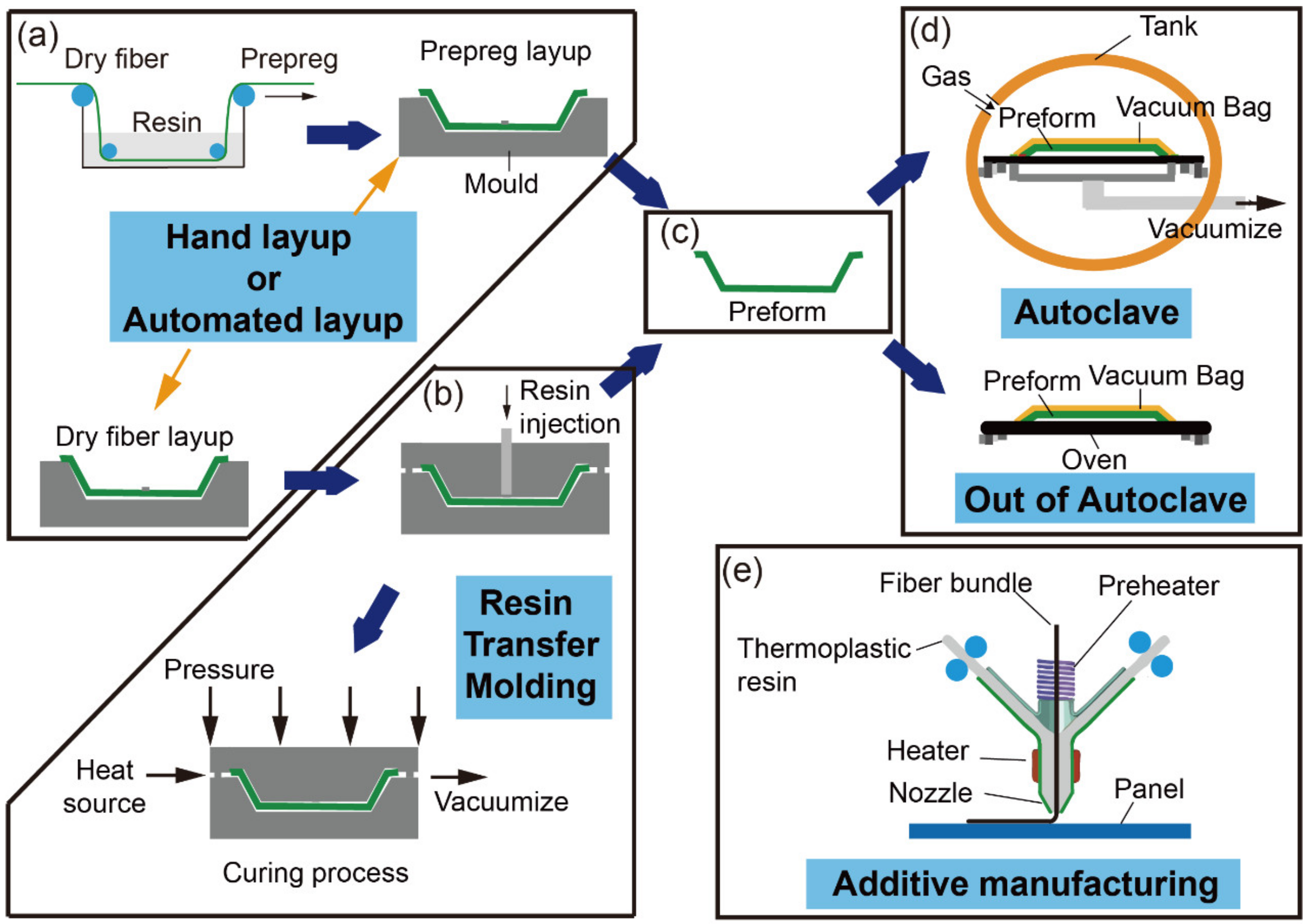
2. Traditional Molding Technology

2.1. Autoclave

Autoclave molding technology started in 1940s and was applied to manufacture thermoset composite components for the main bearing structures of aircraft. An autoclave is a pressure vessel equipped with a heating system. It currently is one of the most mature composite structure molding technologies, and accounts for more than 80% of the total production of aerospace composites [25]. Autoclave curing technology is a method of curing thermoset-resin-based composite structures using high-temperature compressed gas inside a tank [26]. A schematic diagram of a typical autoclave molding system is shown in Figure 2a. Under high temperature and pressure, composite structures have high fiber volume content, low porosity and reliable mechanical properties, which means autoclave molding technology has the advantage of good product repeatability. Therefore, autoclave molding technology has been one of the most important methods for producing high performance composite structures in the aerospace industry such as composite wings, fuselages, and other load-bearing components. Well-known autoclave manufacturers include Terruzz, ASC Process System, Didion’s Mechanical, etc.
The cost of manufacturing FRP composites by autoclave are extremely variable depending on the specific production process. Currently, large composite components require huge or super huge autoclaves to ensure the internal quality of the parts, so the size of autoclaves is also increasing. The world’s largest autoclave, 9.88 m in diameter and 34.5 m in length, was built in 2006 by ASC for manufacturing the Boeing 787 fuselage (Figure 2b). The huge autoclave realizes the integrated molding of large composite structures, which greatly reduces the number of parts and fasteners and the mass of aircraft. Furthermore, the surface of the aircraft will be smoother, and the wing–body fusion aerodynamic layout is easy to achieve. Above all else, aircraft safety can be improved due to the absent of weak joints.

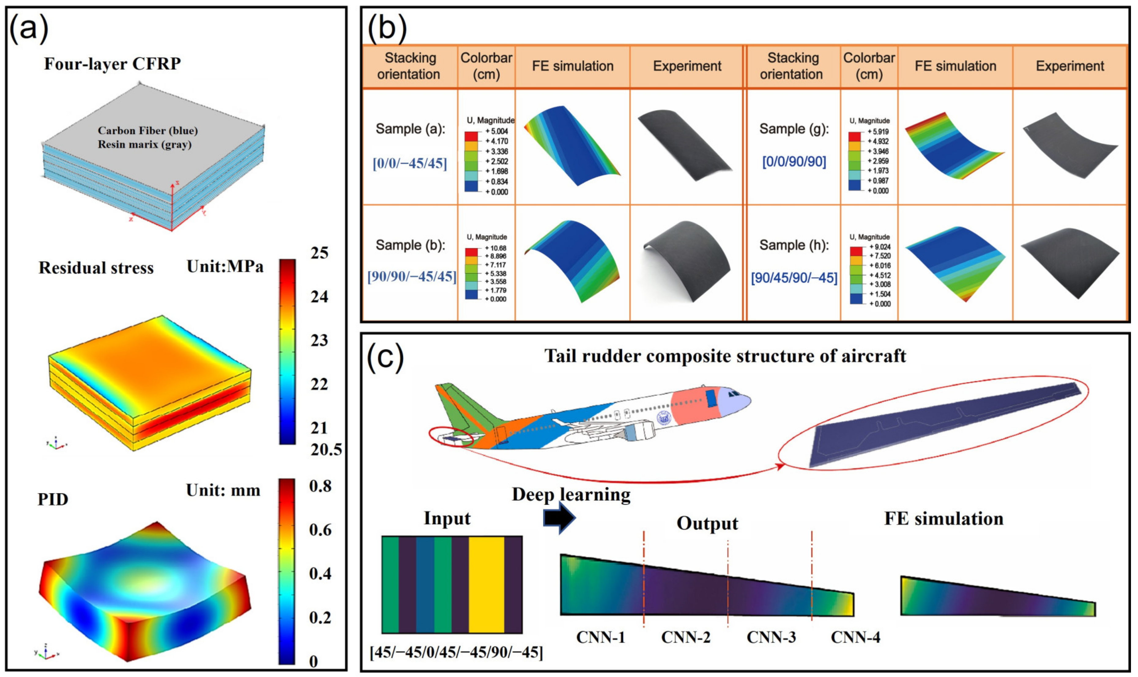
2.1.1. Curing Process

During the curing process, the internal temperature and pressure of autoclaves are the most important parameters; this is attributed to their influence on the final performance of composite structures, including the surface quality, porosity, fiber volume fraction, mechanical properties, and reliability of the composite [30]. Additionally, as the size of autoclave increases, the internal temperature will distribute unevenly, resulting in residual stress and unexpected deformation of structures.
Because of these facts, monitoring and controlling the temperature and pressure in real time are necessary. Fiber Bragg grating (FBG) sensors, which are optical fiber-based, are now regarded as a mature technology in structural health monitoring (SHM) [31,32,33]. Sonneefeld et al. [34,35] reported on the use of a fiber Bragg grating (FBG)-based sensor written in a photonic crystal fiber (PCF) to monitor the cure cycle of composite materials. The embedded FBG sensor has been calibrated for transverse and axial strain as well as for temperature changes. These sensors allow us to gain insight into the composite cure cycle in a way that would be very difficult to achieve with any other sensor technology. Ding et al. [36] accomplished FBG sensors embedded into the CFRP shaft using a separating mandrel to precisely detect real-time temperature and strain during the curing process. Cable [37] used optical fiber sensors to monitor in real time the temperature and pressure inside composite structures during the curing process. The diameter of the optical fiber is only 100 μm, so it can be preinstalled inside the structures. Rocha [38] embedded FBG into CFRP laminates for ambient temperature curing, post-cure monitoring, and monitoring and evaluation of residual strain.
Numerous sensors are needed when the structures’ size becomes large, and the sensors are left inside the structures forever, which has an impact on the composite curing process and performance. Lynch et al. [39] exploited the nature of incompressible liquids to transmit pressure by means of a thin syringe with a 90° tangent angle attached to a pressure transducer, using a resin with no curing agent added inside the thin tube to transmit liquid pressure. Subsequently, a resin pressure online measuring system was established based on the principle of pressure transfer in liquid to measure resin pressure during the autoclave curing process [40]. Here, a probe with small outer diameter was used to decrease its dimensional effect on the curing process.
Besides monitoring the curing process, modeling the process is also an effective way to understand the mechanism. Nevertheless, composite curing is a thermo-chemo-mechanical coupling process consisting of a series of complex physical and chemical changes [41]. The most commonly used method is to divide the model into three independent sub-models: the heat transfer-curing model, the flow and consolidation model, and the stress deformation model [42,43,44,45]. The mathematical model and neural network-assisted approaches are the two main ways to model the thermal conductivity [46,47], curing reaction kinetics [48,49,50], resin flow [51,52], volumetric change [53,54], etc. Compared with the mathematical model, the neural network-assisted approach exhibits higher efficiency and is helpful for conducting optimization research.

2.1.2. Curing Process-Induced Deformation

Under the influence of extrinsic curing parameters and intrinsic material properties, residual stress will be generated, and leads to the curing process-induced deformation (PID) of composites; that is, the shape of the manufactured components differs from the designed structure (Figure 2e). The deformation even exceeds the assembly tolerance, resulting in the scrap of parts [55]. For intrinsic reasons, PID in thermosetting composites significantly depends on the interaction of thermal-induced volumetric change and polymerization-induced volume shrinkage, which is usually referred to as chemical shrinkage [41,56]. More research pointed out that the specific heat, glass transition temperature, thermal expansion coefficient, chemical shrinkage coefficient, and thermodynamic coefficient are temperature and time dependent. According to Wang et al. [41], the fiber orientations, stacking sequences of layers and the designed geometry shape and size of composites also affect PID. Many researchers have investigated the link between PID and extrinsic curing parameters, including the mold, curing process, curing temperature, pressure, etc. For instance, due to the influence of the shear force between the tool and the part and the pressure, the resin flow and compaction happen during the curing process. Fiber wrinkling and redistribution may happen, especially in the corner of the parts (Figure 3). Therefore, the stress distribution can be affected significantly by the extrinsic parameters and lead to a change in the deformation during the process. Fernlund et al. [57] studied the curing deformation of C-shaped and L-shaped members, and pointed out that the member deformation is closely related to the curing regime and the curing mold.
Some researchers have used numerical analysis and artificial intelligence to construct a fast PID prediction approach. Dai et al. [58] proposed a multi-physics coupling numerical model for the thermosetting of resin composites to forecast residual stress and deformation during the curing process. The composite shows significant residual stress and PID (Figure 4). Fan et al. [59] proposed an efficient prediction method to elucidate the PID contours of composites with different stacking sequences by combining the finite element (FE) method and a convolutional neural network (CNN). Firstly, FE simulation was experimentally verified using rectangular laminates with 12 types of stacking sequences. Then, this deep learning method was employed to study the PID contours and gives a high accurate and fast assessment of a tail rudder structure after training.
Figure 3. Curing process-induced deformation. (a) Effect of flat tool-part interaction; (b) Effect of L-shape tool-part interaction (Reprinted with permission from Ref. [41]. 2023, Elsevier); (c) Resin rich and wrinkle in the corner [60].
Aerospace 10 00206 g003
Based on curing deformation mechanisms, several PID control methods have been proposed, including ply stacking sequence and fiber orientation optimal design, curing parameter optimization and real-time controlling, and geometric compensation. The first one is optimizing the stacking sequence of laminates. Some results indicated that symmetrical layup and similar isotropic stack sequences have less spring distortion [61,62,63]. As shown in Figure 4b, different stacking sequences lead to various deformation. In the experimental results conducted by Gajjar et al. [64], the quasi-isotropic sequence has a much smaller spring in angle compared with the unidirectional orientations in L-shape parts. Kenan et al. [65] found that wrinkling the fibers of first stacking prepregs on a flat plate and then bending the whole stack to conform to the surface of a mold can decrease the PID of non-flat composites.
As previously mentioned, curing parameters significantly affect PID. Hence, developing approaches to monitor and control the parameters is essential. Through real-time monitoring of factors such as defects, strains, stresses and fiber deformation during the curing process, one can optimize the curing process to achieve product performance and manufacturing accuracy improvement. Chen et al. [66] developed an in situ strain monitoring method to adequately understand the influence of the resin curing cycles on process-induced strains of composite cylinders. According to the results, they concluded that the accelerated curing process could significantly improve strain accumulation efficiency. The heating and cooling rate effect on the PID were studied by Feng et al. [67].
To control the temperature of the entire part simultaneously during the curing process, a microwave curing setup was developed [68,69] which reduces the temperature gradient inside the part and improves the curing efficiency. However, the uneven temperature distribution still exists in the composites caused by the uneven resonance of the electromagnetic field. Zhou et al. [70] presented a method to solve the problem by continuously monitoring and compensating the uneven temperature distribution in real time. In addition, the increases of fiber volume fraction can also alleviate the curing deformation because the distribution of internal stress in a composite with low resin volume fraction is more even [71,72]. Furthermore, several researchers focus on resin modification, which is attributed to the fact that the type of resin directly determines the curing shrinkage, one of the main factors affecting curing deformation. For example, with the addition of 5% silica particles, the curvature of flat plate composites reduced from 4.3243 to 2.0973 mm, according to results from Shaker [73].

2.2. Out of Autoclave

Autoclave molding technology requires maintenance of a high temperature and pressure environment for a long time during the curing process, which results in high energy consumption and economic cost, especially for the larger autoclave in the aerospace industry. Attributed to this reason, more research activities have shifted to the low-cost curing technology “out of autoclave” [74]. In OoA, composite structures are sealed inside a vacuum bag only, and cured in an oven or heat blankets rather than an autoclave. As it has no requirement for expensive equipment and lots of energy, the use of OoA can significantly reduce production costs. For example, the MC-21, led by Russia’s Aero Composite, was the world’s first commercial aircraft that used the OoA technique to manufacture composite wings, as shown in Figure 2f. The manufacturing cost of the wing is only one-seventh of that manufactured by autoclave molding technology [17]. So far, OoA has been used in many experiments of aircraft or even spacecraft, such as Virgin Galactic’s Spaceship 1, Boeing’s X45A unmanned fighter jet, and fairings for space launch systems [75].
Monitoring the curing process during OoA is also important and attracts much attention. Although, since the monitoring methods mentioned in Section 2.1 can also be used in OoA, and we have discussed them adequately, we now focus on the disadvantage of OoA compared with autoclave molding technology.

Porosity and Fiber Volume Fraction

As opposed to those in the autoclave molding process, composite structures in OoA are cured only inside a vacuum bag, which means that just one atmospheric pressure is achieved. Under the low pressure, when autoclave-used resin is applied in OoA, the porosity of a fabricated part is up to 5% to 10%. Besides, the low pressure also leads to a low fiber volume fraction (Figure 2d). Therefore, the primary challenge of OoA is in reducing the porosity of composite structures and improving the fiber volume fraction [76].
For the problem of high porosity, there are two main technical solutions. One is to adjust the rheological properties of the resin so that the air and volatile fraction can escape as much as possible before the resin gels; the other is to improve the process technique so that the volatile fraction in the prepreg can be discharged more easily during the preparation process. A special resin system has been developed by Centea et al. [77] to evacuate voids efficiently. That said, the quality of composite structures manufactured by this process is still inferior to those processed in the autoclave.
The other solution is double-vacuum-bag (DVB) technology, invented by NASA in 2004, as shown in Figure 5 wherein two vacuum bags are applied to seal composite components and there is a steel diaphragm with holes between the two bags [78]. In the first stage of the process, after the space between the two bags was vacuumized completely and most of air inside the inner bag was extracted, an atmospheric pressure is applied on the outer vacuum bag, while a fairly lower pressure is inside the inner vacuum bag. That is, the outer vacuum bag is collapsed onto the stiff diaphragm and inner vacuum bag is “ballooned”. Low pressure inside the inner bag still produces near-vacuum environment on the composite so that volatiles are free to escape by the vacuum suction. In the second stage, air is filled into the middle space and the inner bag is vacuumized completely, so that more than one atmospheric pressure can be applied on the composite. This pressure helps to consolidate the laminate during curing process. With proper tooling designs, DVB can produce products with almost no void ratio and can be adapted to any composite manufacturing process. For high-viscosity resin systems, DVB can also provide sufficient additional pressure to ensure the quality of the molded products [79]. The DVB was verified by Rana et al. [14], who presented a comparison between composite samples manufactured with vacuum infusion molding employing single- and double-bag technology. The results show that employment of double-bag technology improved the inter laminar shear strength and flexural strength as compared to samples manufactured using the single-bag method. This improvement in properties was associated with volatile management and compaction of fiber in dry and saturated conditions. Therefore, this technology was suggested in order to obtain improved properties.
As for the problem of low fiber volume fraction, Northrop Grumman, a company in the USA, in the manufacturing process of composite fuel storage tanks developed a very thin unidirectional prepreg tape specifically for automatic taping which is only half the thickness of standard prepreg tape. This allows the storage tank walls to contain more layers at the same thickness, increasing the fiber content and the overall pressure resistance of the tank [80]. DVB can also reduce fiber volume fraction due to the high pressure applied to the inner bag.

3. Liquid Composite Molding

In previous cases, prepreg is laid up manually or automatically to constructure preforms and then cured inside or outside an autoclave. Another category of molding technology is called liquid composite molding (LCM), where a preform is fabricated with dry fibers on a mold surface and then liquid resin (or melted resin film) is injected into the preform enclosed in the mold (Figure 6a). The resin will infiltrate the preform, flowing between fibers, and the preforms will finally be cured at the elevated temperature [15,81,82]. Since the LCM process enables the manufacture of large composite parts with high specific mechanical properties at a significantly lower cost and shorter cycle time, it has attracted extensive attention in industry [18].
Compared with the autoclave forming process, LCM has significant advantages, manufacturing structural parts with large local thickness and complex structure characterized by double-curvature shapes with remarkable precision. For example, LCM technology has been used to manufacture about 1/4 of the overall number of composite parts for the fourth-generation fighters, F-22 and F-35, including the fuselage frame, fuel tank frame, tail beam and rib, wing intermediary beam and so on [83]. The most typical component is the wing sine wave beam, which is about 4.5 m long. LCM reduces the number of parts in the vertical tail and more than 60% of the total cost.
Several variants of the LCM process have been developed. The three main variants are (Figure 6): RTM, vacuum-assisted resin infusion (VARI), and resin film infusion (RFI). RTM is characterized by closed molds, and high pressure can be achieved; VARI is characterized by open molds on one side only, and an atmospheric pressure only; RFI is characterized by film-form resin initially laid between molds and preforms, with open molds on only one side and an atmospheric pressure only [84]. Although the basic principles of the three methods are similar, the RTM process is relatively efficient and automated. Additionally, the final composite structures produced by RTM have the best internal and external surface quality compared to the other two processes. The following discussion will focus on RTM.

3.1. Resin Transfer Molding
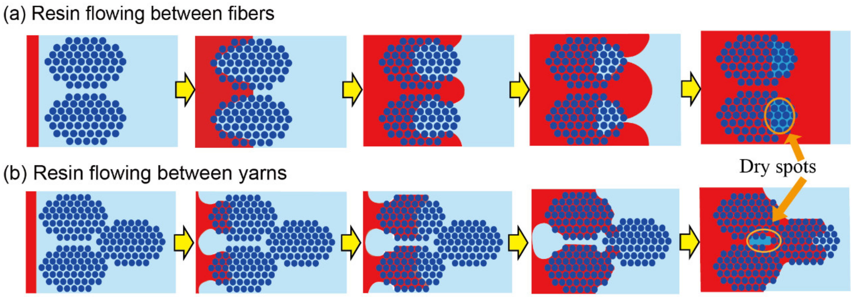
In the RTM process, a dry fiber preform is first laid in the mold cavity, and then the resin is injected into the closed mold with the pressure provided by vacuum or injection device until the entire cavity is completely filled with resin, and finally the resin-infused preform is cured, cooled and demolded [85,86]. Compared with VARI and RFI, the rigid mold in RTM can provide higher pressure to accelerate resin flow, and reduces voids in composite structures. Hence, RTM is a promising process for obtaining high-quality products without expensive equipment, leading to the wide usage in fiber-reinforced products in the civil, aerospace, and automotive industries [87].
In the early days, RTM was considered unsuitable for highly loaded aerospace components. However, as RTM technology develops, and under the support of the U.S. Department of Defense, the aerospace industry has increasingly adopted RTM technology for molding high performance composite structures. For example, in the drivetrain of a light attack helicopter, RAH-66 Comanche, designed and manufactured by Boeing Sikorsky, the performance of PR500/IM7 composites formed by RTM is comparable to that of composites produced by autoclaves. RTM enables the production of the RAH-66 at a lower cost [88]. In recent years, RTM parts have been popularly used as primary and secondary structural components of spacecraft; this is attributed to their excellent dimensional tolerance control and the advantage of ensuring high surface quality and net dimensional forming [89]. For instance, the ESA Ariane 5 rocket booster motor attachment skirt is manufactured with carbon fiber preforms using the RTM process [90].

Resin Flow

During the research and development of the RTM process, it was found that the RTM process’ technology has some shortcomings, mainly focused in three aspects [91,92,93]:
  • The fiber volume fraction of components is low.
  • Resin is poorly impregnated with fibers, resulting in many dry spots inside the components.
  • Components with a complex internal structure cannot be molded integrally.
For RTM, the resin flow process is the most important issue [94]. Dry spots usually emerge during the resin flow stage, when the resin fails to impregnate the preforms. This process has been widely analyzed and simulated. The dry spots formation mechanisms were revealed by some researchers [76,95,96,97,98,99].The main reasons include mechanical air entrapment in composites, moisture absorbed during material storage, moisture dissolved in the resin and the different flowing speeds of resin between fibers and yarns (Figure 7).
Many researchers have been looking for ways to eliminate dry spots. For simple molds, an analytical solution for the relationship between wet length, resin filling time, and pressure distribution was obtained by Cai et al. [100]. Several trial-and-error experiments have also been conducted to eliminate dry spots by optimizing process parameters [101]. However, the trial-and-error method is costly and time-consuming. Therefore, numerical simulation was adopted to determine the number and location of injection ports and vents in the mold, as well as the injection pressure for reducing the numbers of dry spots [92,102,103]. In some cases, flow-guiding medium is used to lead and accelerate the flow of resin (Figure 6b); although, more research on the mechanism of resin flow at the mesoscale and microscale is essential to address the generation of dry spots.
Besides, monitoring the front position of the resin flow in real time and controlling the parameters in situ using sensors are also helpful [26,95,104]. Inserting an FBG sensor in the dry fibers is the earliest proposed method of monitoring resin flow around the sensor [105,106];, however, this method inevitably misses many dry spots. Some full-field monitoring techniques without any un-sensing space were proposed, for example, an interdigital electrode array film, which can even control the resin flow speed and temperature by dielectric heating at arbitrary positions on the film [107,108]. In recent years, new monitoring sensors were constructed with functional materials, such as graphene-coated glass fabric sensors [109], a piezoelectric material-based sensor network [110,111], and electrically resistive sensors made of reinforced continuous carbon fibers [103,112]. Moreover, a non-invasive dielectric monitoring system for unsaturated and saturated flow tracking was developed based on the assumption that capacitance variations between two parallel plates are imputable to variations of the dielectric material [113]. These monitoring techniques are presented in Figure 8. Summarily, an advanced monitoring system should have the ability to monitor resin flow, dry spots, temperature, pressure and so on in full-field, or even to control the temperature, resin flowing speed and direction.

3.2. Variants of RTM

To improve the process performance, several processes have been developed from the primary RTM process. Three main variants of RTM are low pressure RTM (LP-RTM), high pressure RTM (HP-RTM) and compression RTM (CRTM) [114,115,116], as presented in Figure 9a–c.
LP-RTM use an injection pressure of 10–20 bar and a final hydrostatic pressure similar to the curing pressure in VARI, so it is cheaper and commonly used for manufacturing aerospace engineering parts [86,117]. However, the injection pressure in HP-RTM is 60–100 bar, higher than that in LP-RTM [118,119]. The high pressure can accelerate the resin flowing speed to reduce the injection time. The semi-rigid mold and rigid mold are used to form a cavity for a preform, and vacuum-sealing technology is adopted. An advantage is that the mold can be used repeatedly, which greatly reduces the cost of the molds. The aerospace industry has used LP-RTM for a long time to produce many composite structures, such as thousands of carbon fiber reinforced plastic (CFRP) fan blades and containment magazines for commercial aircraft engines. Airbus has even used RTM to produce a 7 m-long monolithic multi-beam flap prototype for the Airbus A320.
HP-RTM’s high-speed mixing process allows the use of highly reactive resins, solving bottlenecks in injection and curing. Hirsch, a composites and resin supplier, demonstrated that HP-RTM reduced the cost of A350 hatch frames by 30%.
C-RTM [116,120] is an advanced composite molding process for high-fiber-volume components. Unlike the closed mold in RTM, in C-RTM, a gap is left between the upper mold and the preform before the curing process (Figure 9c). The resin flows through the gap during injection and closes the gate after a certain amount is reached. The upper mold then moves down to close the mold and squeezes the resin into the preform. With the help of compression, the aim of high fiber volume fraction can be achieved. C-RTM also allows the injection of high viscosity resins. The molding pressure of C-RTM is only 6 bar, i.e., much lower than the pressure of HP-RTM, so low-pressure injection systems and lower tonnage presses can be used to reduce cost. The process achieves aerospace-grade quality composites for both large, thin parts and smaller, more complex-shaped parts.
Techni-Modul Engineering saw an opportunity to adopt C-RTM for aerospace in the Clean Sky 2 “Optimized Composite Structures” (OPTICOMS) project [8]. OPTICOMS is organized in Work Package B-1.2 (“More Affordable Composite Structures”) to explore prepreg and liquid resin methods to reduce production costs for small aircraft (e.g., regional airliners) through integrated structures and automated manufacturing. The injection time reduction offered by C-RTM will be even greater for large components such as full wing skins or helicopters.

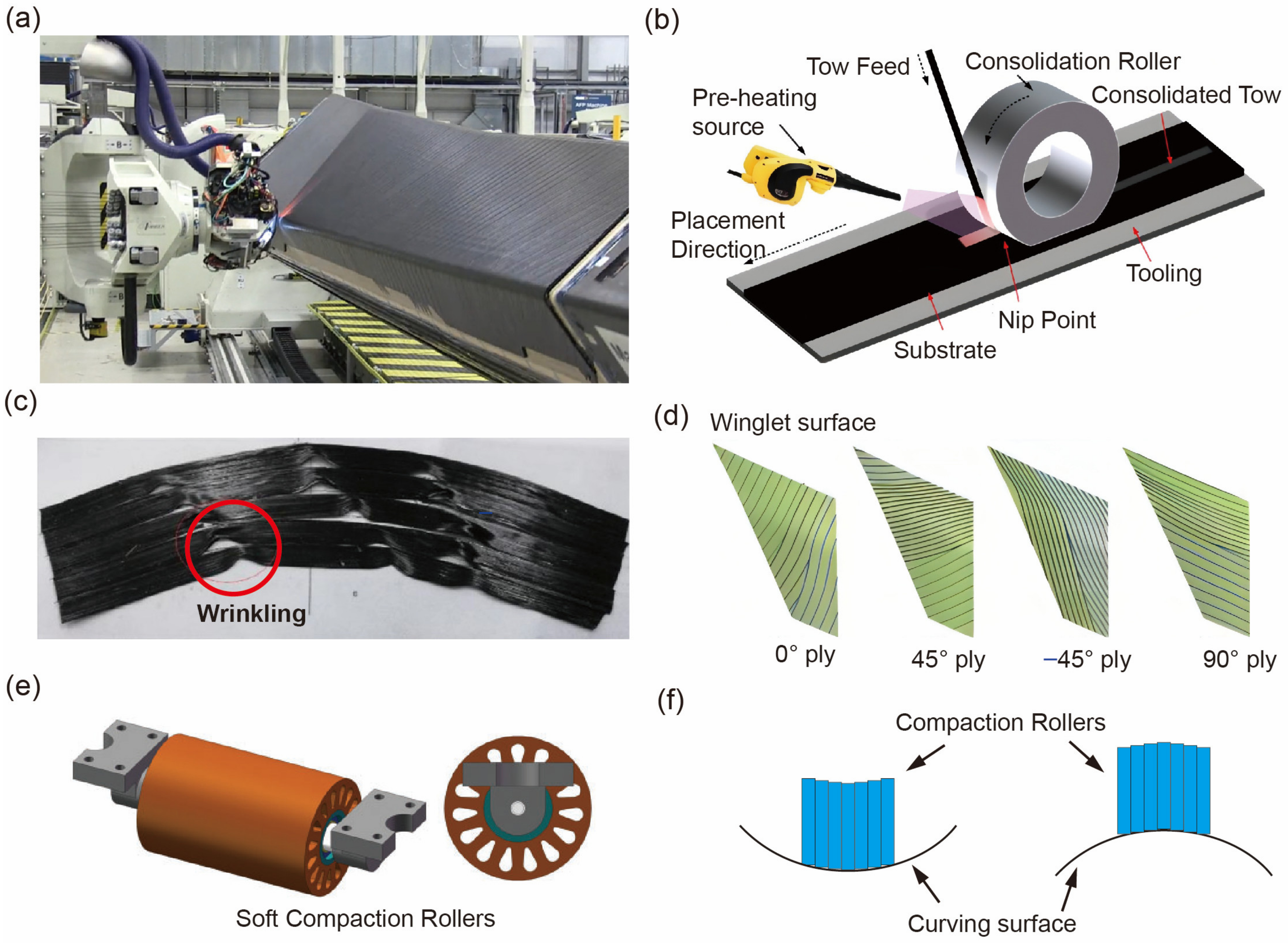
4. Automated Layup Technology

Layup technology is vital during the manufacture of FRP composites; it not only affects the mechanical properties of FRP composites but also the production efficiency. However, the conventional hand layup method is time-consuming and labor-intensive, and inevitably generates defects inside composites. To improve production throughput and the quality of the composites, computer-aided ALT, including filament winding, automated tape laying and automated fiber placement, for continuous FRP composites was developed along with the increasing commercialization of composites [121,122].
FW has been used for decades to make axisymmetric FRP components such as pipes, pressure vessels, pipe fittings and drive shafts [10]. ATL and AFP can automatically place tapes or fibers to construct composite structures and are increasingly used in the manufacturing of large structures of airplanes such as fuselages and wings. In ATL, only one tape is manipulated a time, and the width of the tape is even larger than 300 mm [123]; meanwhile, multiple fiber tows (8~64 tows) can be manipulated simultaneously in AFP (Figure 10a,b), and their widths are only several millimeters so that the paving efficiency can be improved. This is the major distinction between ATL and AFP. Hence, ATL is more suitable for manufacturing large-scale components with a simple structure and low curvature, while AFP can fabricate complex composite structures with high curvature [124]. At present, ALT has been adopted in the aerospace industry to manufacture large-scale composite wall structures of aircraft, such as the wing of the F-22, the tail, horizontal and vertical stabilizing panels of the Boeing 777 and so on. The “clean sky 2” project, which is funded by the European Union, aims to lay the technological groundwork for greener aviation and increase European competitiveness in this field. In this project, a composite outer wing box was manufactured through AFP [125].

4.1. Layup Path Planning

In the ALT process, the quality of layup path immediately affects the mechanical properties of composite structures. The layup path planning is still a main challenge, although ALT has been adopted for complex structures. Specifically, the poor quality of tow compaction, the easy deviation of the path direction, and the small turning radius will cause various types of defects, in particular the overlap of fibers, gaps between fibers, and resin deposits [1], resulting in the performance of the composite structures being unable to meet the expected requirements.
The layup path quality accounts for the mechanical properties of final components. The generated path aims to satisfy both manufacturing requirements and performance requirements [131]. Many path generation methods have been reported. For example, by projecting reference lines on the mold surface, the initial path can be generated, and the next path is offset from the initial path by a constant geodesic distance to ensure that there are no gaps and overlaps [132]. However, this method ignores the need to meet design and manufacturing requirements. The fixed angle method is another approach; it complies with design requirements but may lead to fiber buckling and wrinkling on complex surfaces [133]. Compared with the previous methods, the variable stiffness method is more adaptable due to its designability for generating different paths. Bittrich et al. [134,135] generated variable stiffness paths on a perforated plate and a cylindrical surface, and the performance of the components is significantly improved.

4.2. In situ Consolidation Process Parameters

Both thermosets and the thermoplastic prepreg can be used in AFP to form FRP composites. However, the composite laminated with thermoset prepregs needs to be post-cured in autoclaves, which is still time-consuming. In contrast, the manufacturing of fiber-reinforced thermoplastic polymer (FRTP) composites can save much time due to their short consolidation cycles. For FRTP composite components, their fabrication using ALT processes can complete in situ consolidation (ISC) to further shorten the processing time, because the consolidation and placing process can proceed almost simultaneously and autoclaves are no longer required [11]. In addition, FRTP composites also have other advantages, including higher toughness, long shelf life, ease of repairing and potential for recycling [136]. For example, polyether ether ketone (PEEK) has high toughness, damage resistance and excellent environmental resistance. PEEK-based FRTP composites can maintain their mechanical properties in environments with elevated temperature and moisture. Considering these advantages, carbon fiber-reinforced PEEK composites are being widely used in the aerospace industry [137,138]. Boeing, Automated Dynamics Company, NASA, Fokker Services and other aviation organizations have successively carried out research on FRTP composites, and have manufactured typical structures such as fuselages and wings [139].
During the in situ consolidation process of FRTP composites, thermoplastic resin is sensitive to temperature and pressure. The history of temperature and pressure directly affects the crystallization quality of resin and the mechanical properties of composites. Some efforts have been made to study key process parameters, including temperature, heating and cooling rate, pressure and laying speed in the in situ consolidation process. For example, Song et al. [140] investigated the influence of cooling rate and cooling time on the non-isothermal crystallization behavior of the matrix material based on a proposed non-isothermal crystallization kinetics model, and found the maximum processing speed at different cooling speeds. They found that the compression strength and the interlaminar shear strength increase with the enhancement of the crystallinity, while the impact strength decreases along with it. Furthermore, they proposed an infrared heating technology with fast response and high efficiency to control the temperature precisely [141]. Besides the infrared heating technology, flashlamp heating systems are a recent addition to the available radiative sources for ATP applications [142]. The flashlamp’s frequency and pulse duration can be operated to control the energy delivered to materials. A wide parameter space leads to greater process flexibility and the potential for advanced process design and online control in the ATP process.
As for the effect of pressure, Jiang et al. [130] analyzed the distribution of compaction pressure on prepreg tows, and optimized the design of a roller to improve pressure uniformity. This approach enhances the bond quality between layers. They then established a theoretical model of the compaction pressure distribution for layup on an irregular curved surface in order to predict the compaction pressure distribution before the placement, so that the layup quality and possible defects can be analyzed in advance [143]. Bakhshi and Hojjati [144] presented that a roller made of a soft material can provide the appropriate uniform compaction. Segmented compaction rollers [145,146] that consist of multiple small rollers also have the capability to distribute pressure evenly on the contact area (Figure 10e). Furthermore, Heider et al. [147] have proposed a system to control parameters, which combines a neural network (NN)-based model numerical and neural network optimization, and an infrared thermal imaging camera to sense the temperature profile on the part surface.

4.3. In situ Inspection and Defect Detection

In addition to the optimization of layup path planning and the consolidation process to enhance the mechanical properties of composites, in situ monitoring and defect detection during the layup process are also important. However, every ply is still manually inspected by eye in many cases, and this manual inspection takes significantly more cycle time than the AFP layup itself [148]. For example, the AFP layup time of a 787 fuselage performed by Boeing is 24% of the total floor-to-floor cycle time. Yet, the cycle time devoted to layup inspection and rework comprises 63% of the cycle time [149]. Thus, efforts are underway to use sensors to automatically inspect AFP layers. One such effort was funded by NASA and performed by the Flightware company in Houston, USA. They have developed an in situ AFP inspection system based on profilometry and laser line scanning [13]. The automated ply inspection may reduce total cycle times by 20% [148].
The monitoring of compaction and temperature during the layup process is also crucial for manufacturing high quality composites. Fiber Bragg grating (FBG) sensors have been used to monitor the layup conditions via measuring the reflected wavelengths, which are related to compaction pressure and temperature [150,151]. Based on FBG sensors, Ebrahim et al. [152] simultaneously measured strain, temperature and acoustic emissions in composite laminates.
Due to the complexity of the AFP process, defects often appear in the composites, such as gaps, overlaps, fiber waviness, and twisted tows [152]. Woigk et al. [153] investigated the effect of gaps and overlaps on tensile and compression properties experimentally. In the experiment, “gaps and overlaps” specimens exhibit strength reductions in tension and compression of 7.4% and 14.7%, respectively. Some online defect detection techniques were developed to identify the defects during the AFP process. Oromiehie et al. [154] used optical FBG sensors to identify the misalignment defects through reflected wavelength changes. However, for small actual defects under the micro scale, the applicability of the method needs to be further confirmed. Another online method based on a thermal camera with image processing was presented by Denkena et al. [155], which can identify gaps, overlaps, twisted tows, and bridging derived by analyzing the visible temperature difference between the layup tow and the surface underneath via thermal images. To identify defects rapidly and automatically, they further used convolution neural networks (CNNs) to classify the thermal images of the CFRP material, which can even identify several prepreg materials and different material defects during the AFP process [156]. Nevertheless, this method can only detect surface defects. Since defects can change the characteristics of stress wave propagation, such as the amplitude, the Manhattan distance, and mean stress, internal defects can be detected by monitoring stress wave change [1]. The continuous loads induced by the process itself can be used as an excitation source without another external excitation [157].

4.4. Characteristic Prediction

Since the properties of ALT composites are influenced by a variety of process parameters, accurately predicting the properties of the composites is still a challenge. The combination of ALT with AI can generate an intelligent technique for the challenge. For example, Wanigasekara et al. [158] developed an intelligent model to learn the complex behavior of composites and used it to predict the various characteristics of the composites. They also proposed a neural network-based inverse predictive model for an AFP-based manufacturing process using virtual sample generation (VSG) techniques. The predictive model can determine the input conditions to obtain a product with the desired characteristics [159].
However, the application of intelligent methods is limited so far due to the lack of available data that are the basis of training intelligent models. This leads to the small data learning problem. More efforts are being made to solve this problem.

4.5. Advanced Placed Ply

Although ALT has been widely used in manufacturing composite components with complex shapes, the manufacturing of composite components with large curvature, variable stiffness, and complex structures requires more advanced ALT. Traditionally, ALT composites consist of unidirectional layers, each constructed by aligning all the tows to be parallel to one another, and ensuring that each tow is adjacent to the previous tows without leaving any gap or overlap between them [160]. Numerous pieces of research have found that gaps and overlaps reduce composites’ strength [161]. Furthermore, the interlaminar properties of AFP composites are still not strong enough due to there being only resin between layers.
Therefore, a new automated fiber placement, advanced placed ply (AP-PLY), has been proposed by Nagelsmit [160,162] for improving the damage tolerance of composites. As shown in Figure 11, AP-PLY, sometimes referred to as clutch laminates [163,164], creates through-thickness reinforcements by interlacing fiber tows in a pseudo-woven architecture, allowing AP-PLY composites to retain advantageous impact and damage tolerance properties. AP-PLY combines the advantages of fabrics and unidirectional layers in an automated production process so that the composite meso-structure is similar to that of a 3D woven composite known to have better damage resistance characteristics than unidirectional composites [5,160]. However, the curvature of tows and the lower fiber volume fraction caused by increasing gaps may result in the reduction of other mechanical properties such as tensile strength and bending stiffness.
Previous studies have reported significant improvements in mode I interlaminar fracture toughness and compression after impact strength as a result of this novel preforming method [162]. As such, AP-PLY composites are potentially a suitable material choice for aerospace components that are susceptible to dynamic loads, such as engine blades, brackets, nacelles, propellers/rotors, turbine casings, and wings [165].
Figure 11. Schematics of mesoscale structure of composites manufacturing using (a) ALT, (b) AP-PLY (clutch laminate) [164] and (c) 3D woven [166].
Aerospace 10 00206 g011

5. Additive Manufacturing

5.1. Traditional Additive Manufacturing

With the increasing importance of continuous fiber-reinforced composites in industrial application, additive manufacturing successfully overcomes the defects in traditional composite manufacturing process, including the complex molding process, high cost and long production cycle, and meets the needs of high-quality production [167,168]. Furthermore, with its flexible designability on the shape of the parts and ability to deal with delicate and complex structures, it can also give more choices in fiber orientation, and allow the full utilization of the anisotropic characteristics of composites (compared with traditional isotropic manufacturing process), which further optimizes the performance of the products [169,170,171]. Consequently, additive manufacturing, especially 3D printing, shows great potential in the manufacturing of composite structures.
The development of additive manufacturing has a history of nearly 40 years; especially in the past five years, additive manufacturing has developed extremely rapidly. Additive manufacturing processes for continuous fiber-reinforced composites include fused deposition modeling (FDM), fused filament fabrication (FFF), directed energy deposition (DED) and laminated object manufacturing (LOM) [172]. Among them, FDM is the most widely used additive manufacturing process so far. It prints materials in a layer-by-layer way, which is the most basic form of additive manufacturing. With its simple working principle, low production cost and rapid production efficiency, it provides the possibility of rapid forming of composites [173]. However, the efficiency will be low if the structure is large. A novel approach, a combination of AFP and AM, was developed to achieve better results, especially for large and complex composite structures [174]. Meanwhile, integrating this approach on a robot arm can make complex-shaped surfaces with significantly fewer production defects possible (Figure 12).
In the past five years, there are several crucial innovations in the technologies of traditional additive manufacturing which specialize in printing continuous carbon fiber-reinforced composites (Table 1). Free-hanging 3D printing (Figure 13a) made it possible to print composites that are suspended so that the toolpath can be out of substrate, and more complex structures are appearing to meet the need of some aerospace parts [175]. As the rate of 3D printing is still very low because of the slow heating rate in the nozzle, 3D microwave printing (Figure 13b) was proposed to accelerate the printing rate. Carbon fiber-reinforced composite filaments are quickly heated in the nozzle by a microwave port, and the production efficiency is obviously improved [176]. However, the quality of carbon fiber-reinforced composite parts is unstable because of high porosity, which is the main hidden danger in composite parts. After that, 3D compaction printing (Figure 13c) was proposed to improve printing quality. The print platform has a compaction roller which can roll the composites that have been printed before when printing. This method is useful for reducing porosity in composite parts, and effectively improves their quality [177]. After that, researchers try to expand the application of additive manufacturing to different environments. For example, vacuum 3D printing (Figure 13d) was proposed to deal with space operations. A vacuum environment was built in the experiment and the productions printed in this environment were tested. The experiment proved that the properties of products printed in the vacuum environment were still good enough to be applied to practice. So this technology has the potential to be applied in space operations [178]. In addition, some composite parts have low quality because of the low volume content of fiber. To solve this problem, multiple fiber bundles 3D printing (Figure 13e) was proposed [179]. In this additive manufacturing equipment, the nozzle is modified by adding more access, so that more bundles of carbon fiber may be added. Then, the volume content of carbon fiber in the composites is raised, and they can be used to produce aerospace parts that have better properties.

5.1.1. Path Planning

As ALT, good print path planning is also the basis of high-efficiency manufacturing and high-performance composite structures. Dong et al. [180] have proposed a path planning method with uniform fiber distribution and interlacing in the lattice structure, but the design of this method is complex and difficult to apply to complex structures. A new path planning method based on the distribution of stress field on composite structures under given loads under the tensile or compressive load in use was further proposed by Chen et al. [181]. This method is different from the traditional load-independent path planning method and is suitable for planning the print path of products under an applied load. The mechanical strength of the products has been significantly improved. Previous research has focused on the path planning of small products, but research on the path planning of large components is still insufficient. Bi et al. [182] put forward a path planning method based on contour parallel and direction parallel, which can be used in solid filling and non-solid filling in larger sizes. The method can also be used for the design and production of topology optimization.

5.1.2. Interface Properties

In additive manufacturing, composite structures are generally constructed layer-by-layer, resulting in high porosity and poor interface performance between layers, especially in carbon fiber-reinforced composites [183]. To solve the problem, Congze et al. [184] firstly analyzed the theoretical mechanism of interfacial adhesion, and then experimentally studied the influence of the nozzle and the temperature of substrate on printing properties and interface bonding properties. Their research provides a basis for process parameter optimization, which can improve the precision of printed parts and their interlayer performance. Besides optimizing the process parameters, Zhang et al. [185] improved the adhesive property between carbon fibers and polylactic acid (PLA) resin by improving the pretreatment process of additive manufacturing, and this method also improved the bearing capacity of these products. However, the effect of the impregnation ratio of resin–fiber on interface performance was seldom considered in previous research. Wang et al. [3] proposed a theoretical model to characterize the impregnation behavior of a continuous carbon fiber-reinforced PLA specimen fabricated by FFF. It was proved that the increase in the impregnation ratio can reduce the porosity of the specimen.

5.1.3. Topology Optimization

To make the structure of composites more suitable for additive manufacturing, some researchers combine additive manufacturing with topology optimization to improve the manufacturing process. Fasel et al. [186] combined 3D printing of composites with the flexible mechanism of the aerospace vehicle, and integrated them for use together. By combining the idea of topology optimization, the flight performance of the aerospace structure is greatly improved, while the manufacturing cost is reduced and the applicability of 3D printing of composites to flexible aerospace structures is increased. Zhu et al. [187] have introduced various examples of integrated applications of additive manufacturing and topology optimization in recent years. As an advanced structural design method, topology optimization has been integrated into the production process of lightweight and high-performance equipment. The combination of the two technologies significantly expands the applicability of additive manufacturing, and thus can be widely used in the manufacturing of aerospace equipment.

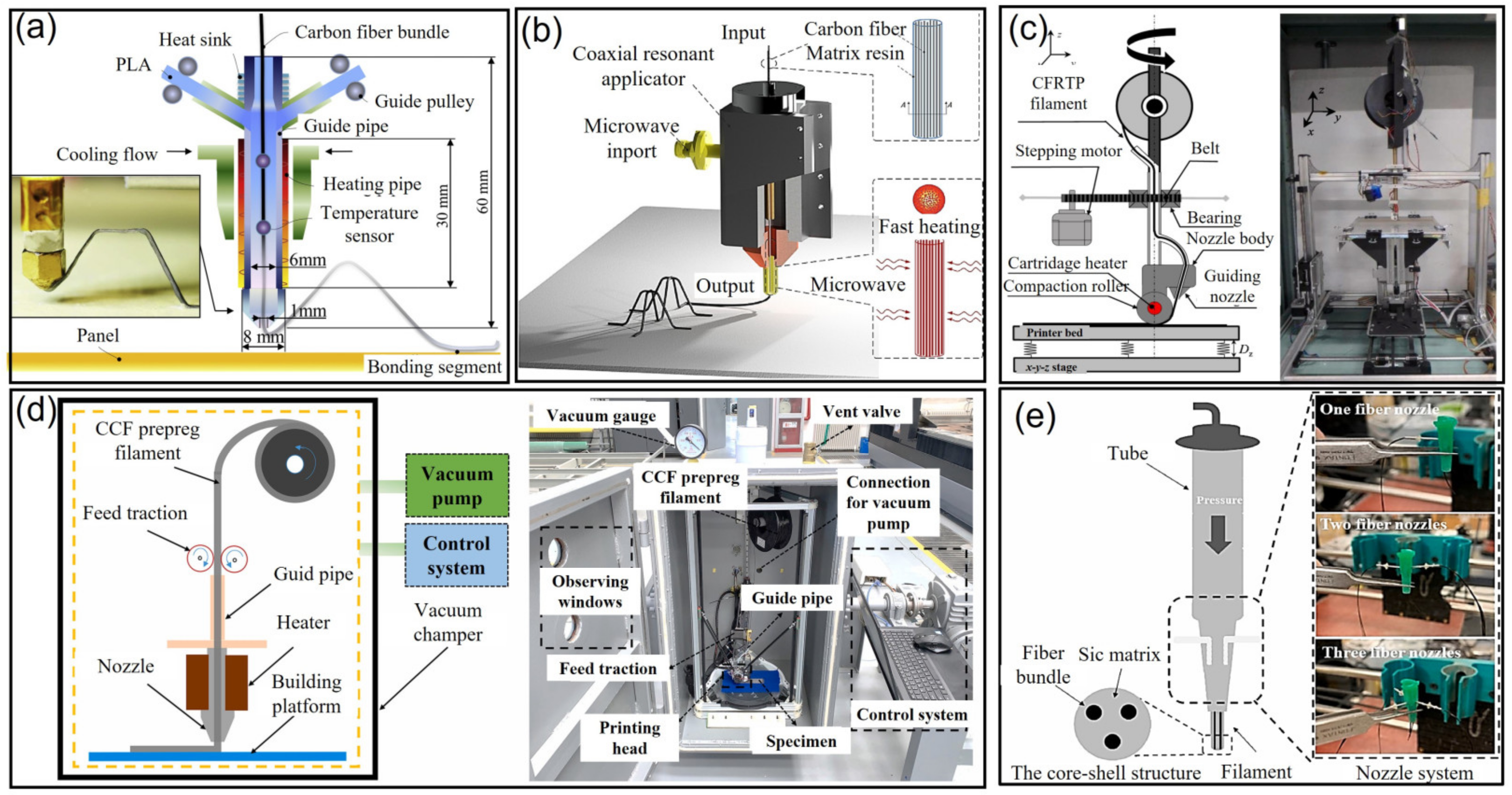
5.1.4. Vacuum Printing

As space missions become more and more important in aerospace strategy, vacuum 3D printing technology has also been gradually developed. Zocca et al. [188] noted that the flexibility of additive manufacturing could be used to achieve the application of space printing technologies, rather than predicting and preparing for all possible machine failures, accidents and other challenges in space missions. This technology for processing space materials has an irreplaceable role in the manufacture and repair of complex parts, equipment and large-scale infrastructure in the vacuum environment.

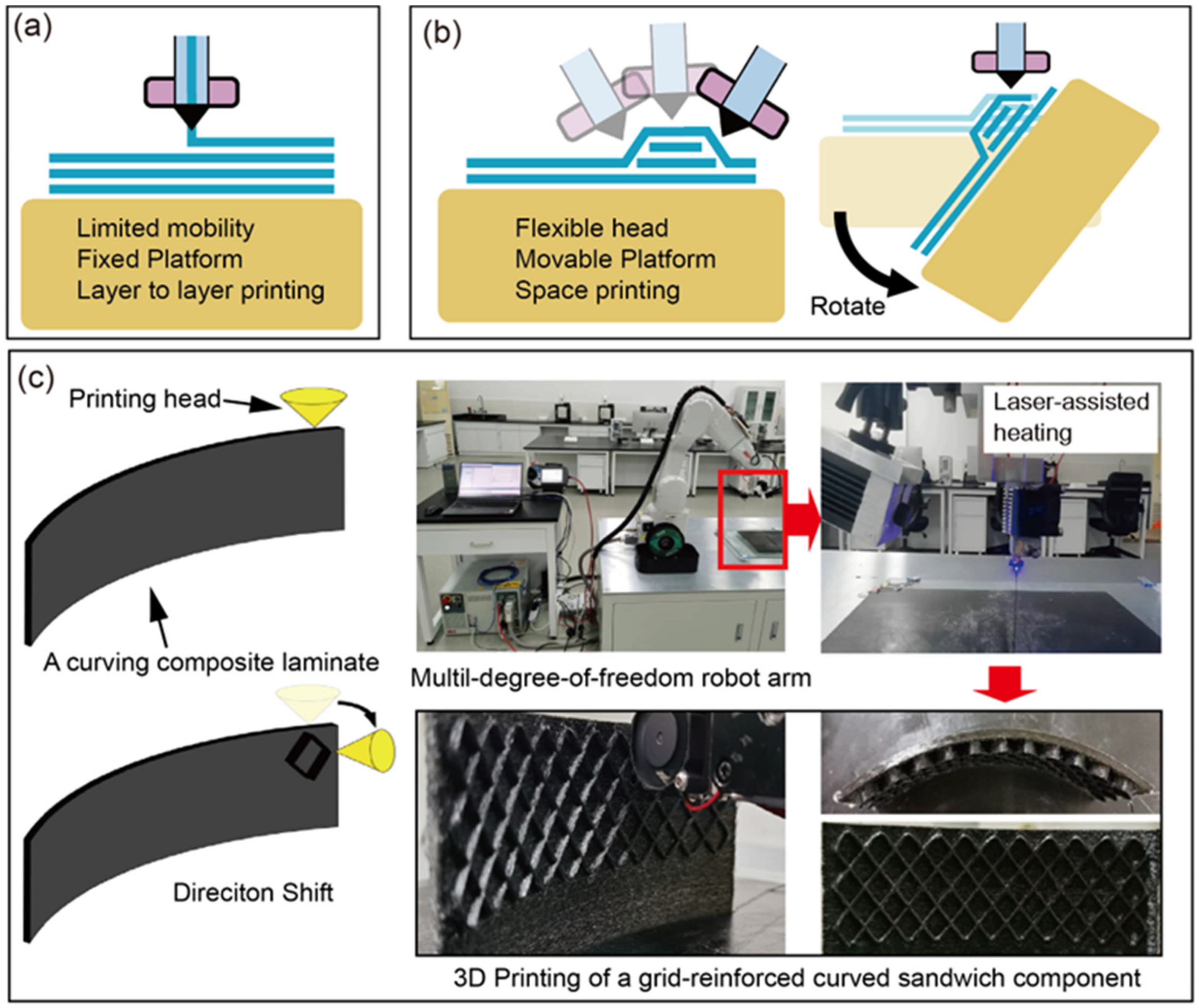
5.2. Muti-Degree of Freedom Additive Manufacturing

Although traditional additive manufacturing has been developed relatively maturely, it is hard to get rid of the principle of “layer-by-layer” production (Figure 14a), and there are several difficult limitations to overcome. First, traditional additive manufacturing must rely on much support to achieve the manufacture of some suspended structures. Too much support is not only difficult to remove, but also increases material consumption and economic cost. Second, during the additive manufacturing process, when the new layer is about to be added, the previous layer has already cooled and solidified. This fact leads to the weakness of the bonding between layers and creates a severe “step effect” [189]. This defect obviously destroys the continuity and directionality of continuous fiber-reinforced composites, and reduces the properties and service life of products. Because of these limitations, traditional additive manufacturing cannot meet the increasing demand for production quality; therefore, a better additive manufacturing process, multi-degree-of-freedom additive manufacturing, was proposed (Figure 14b). In this method, a spatial multi-degree-of-freedom device (such as a five-axes machining center, a six-axes manipulator, etc.) is usually used as a movement mechanism to accomplish non-single direction manufacturing. As shown in Figure 14c, we are committed to using the multi-DOF additive manufacturing method to print a grid-reinforced curved sandwich component with laser-assisted heating, in which the space printing was conducted on the side of the curved panel after the curved panel is fabricated in a layer-by-layer stacking form [190].
Multi-degree-of-freedom additive manufacturing can print products in a more advanced way. Products with complex shapes can be manufactured by adding composites in multiple directions by using a robotic arm that is capable of moving in three or more degrees of freedom. This kind of additive manufacturing extends the designability of fiber orientation and ensures the continuity and directionality of fibers, which can reasonably overcome the problems encountered in traditional additive manufacturing (Table 2).
Because of the many advantages of multi-degree-of-freedom additive manufacturing, researchers have paid much attention to it. Bin Ishak et al. [191] proposed a method of additive manufacturing using a six-degrees-of-freedom industrial manipulator to add layers in multi-planes. Compared with the traditional additive manufacturing, which adds layers in one plane, the path planning of multi-degree-of-freedom additive manufacturing was extended to the scope of space. Although the system expands the scope of path planning, it still does not break through the principle of layer-by-layer printing on a base. Eichenhofer et al. [192] proposed continuous lattice fabrication (CLF) to produce fiber reinforced thermoplastic composites. To really eliminate the use of molds and sacrificial layers, CLF consolidates commingled yarns in situ and allows for the continuous deposition of high fiber volume fraction materials along a programmable trajectory that can be suspended, which break through the principle of layer-by-layer printing.
However, the study of multi-degree-of-freedom additive manufacturing also has many insufficiencies. First, the range of materials available is limited. At present, only thermoplastic materials and a small number of thermosetting materials can be used in additive manufacturing. Second, due to the limited material properties, the strength of composites made by additive manufacturing is lower than that of composites made by traditional methods. Third, the printing process is still limited in factors such as printing time, maximum printing size, printing precision and so on [172]. Therefore, a wide range of future research on multi-degree-of-freedom additive manufacturing is still needed.

Intellectualization Development

As smart additive manufacturing processes and equipment are developed, automatic and autonomous fabrication of advanced composites or multi-material structure can be achieved. In situ process detecting and closed-loop control will be realized by embedding various sensors and actuators into 3D printing equipment [193]. In addition, the concept of multi-degree-of-freedom additive manufacturing is also in line with the development of intelligent manufacturing. Intelligent manufacturing is a kind of man–machine integration intelligent system which is composed of intelligent machines and human researchers. This system can carry out intelligent activities such as analysis, reasoning, judgment, conception, and decision making during the manufacturing process, and extends and updates the concept of automated manufacturing to flexibility, intellectualization and high integration. Intelligent manufacturing connects the manufacturing industry with the internet of things, big data, the cyber–physical system, and artificial intelligence in order to accomplish the manufacturing concepts of intellectualization, synergy, transparency and greenness. Now, intelligent manufacturing is moving in the direction of smart manufacturing, digital twin, and life-cycle big data [194].

6. Summary

Since lightweight fiber-reinforced composite structures were invented, they has been widely used in various industries and create great value, especially in aerospace. Manufacturing technologies have undergone significant development in recent decades, and currently aim to fabricate composite structures economically, automatically, reliably, and smartly, with advanced molding techniques including OoA, RTM, ALT, and additive manufacturing, the advantages, disadvantages and challenges of which are presented in Table 3. Although these techniques have many advantages and are gradually entering the realm of aerospace, there are still many disadvantages and challenges which will hopefully be overcome soon by using intelligent technology. The numeralization and intellectualization of manufacturing technologies for FRP composites are summarized in Table 4. The application of AI to additive manufacturing is still rare due to the very recent development of additive manufacturing using filament fibers.
Since both the design and manufacturing technologies are crucial for the performance of composite structures, an intelligent platform integrating the design and manufacturing technologies of composites based on big data, interpretable machine learning, digital twin, and the industrial Internet of Things will be developed gradually. This platform will provide integrated technology, including design, manufacturing, monitoring, self-optimization, and self-healing during the full life-cycle of composites. Depending on the platform, the total research and development cycle of composite structures can be reduced significantly, their cost will be much lower, and the performance of production will be enhanced. In a word, intelligence technology has the potential to accelerate the development of the design and manufacturing processes of composite structures.
Additionally, the other important development trend is designing and manufacturing advanced aircrafts with smart composite structures which have the abilities of self-perception and self-healing alongside other smart functions. Therefore, design and manufacturing technologies integrating sensors and smart materials on composite structures need to be developed for advanced aircrafts. In addition, many countries are accelerating their exploration of outer space, for example, through the exploration of Mars. With the extension of composites’ application, design and manufacturing technologies will also evolve to fabricate more intelligent composite structures that exhibit better performance.

Author Contributions

Conceptualization, Y.L., W.Y. and W.L. methodology, J.Z., Z.L. and H.Z.; formal analysis, Z.L. and H.Z.; investigation, Z.L. and H.Z.; writing—original draft preparation, Y.C., Z.L. and H.Z.; writing—review and editing, Y.C., Z.L. and H.Z.; visualization, Y.C., Z.L. and H.Z.; supervision, W.Y. and T.Y.; project administration, J.C.; funding acquisition, W.Y. and Y.L. All authors have read and agreed to the published version of the manuscript.

Funding

This research was funded by [The National Key R&D Program of China] grant number [2020YFB0311500]; [The National Natural Science Foundation of China] grant number [12002238]; [Shanghai Pujiang Program] grant number [2020PJD072]; [The National Natural Science Foundation of China] grant number [12202312]. And The APC was funded by [The National Key R&D Program of China] grant number [2020YFB0311500].

Data Availability Statement

There is no data available.

Conflicts of Interest

The authors declare no conflict of interest.

References

  1. Sun, S.; Han, Z.; Fu, H.; Jin, H.; Dhupia, J.S.; Wang, Y. Defect Characteristics and Online Detection Techniques During Manufacturing of FRPs Usiang Automated Fiber Placement: A Review. Polymers 2020, 12, 1337. [Google Scholar] [CrossRef] [PubMed]
  2. Wang, K.; Liu, H.; Zhao, Y. Advance in Automated Fiber Placement Technology on Continuous Fiber Reinforced Thermoplastic Resin Matrix Composites. Aeronaut. Manuf. Technol. 2021, 64, 41–49. [Google Scholar] [CrossRef]
  3. Wang, F.; Wang, G.; Ning, F.; Zhang, Z. Fiber–matrix impregnation behavior during additive manufacturing of continuous carbon fiber reinforced polylactic acid composites. Addit. Manuf. 2021, 37, 101661. [Google Scholar] [CrossRef]
  4. Zhao, Y.; Sun, H.; Li, Z. Manufacturing Technology and Its Application of Aerospace Advanced Polymer Matrix Composites. Aerosp. Mater. Technol. 2016, 46, 1–7. [Google Scholar]
  5. Xie, L.; Jonathan, D.; Garth, M.P. Automation of tow wise modelling for automated fibre placement and filament wound composites. Compos. Part A Appl. Sci. Manuf. 2021, 147, 106449. [Google Scholar]
  6. Van Grootel, A.; Chang, J.; Wardle, B.L.; Olivetti, E. Manufacturing variability drives significant environmental and economic impact: The case of carbon fiber reinforced polymer composites in the aerospace industry. J. Clean. Prod. 2020, 261, 121087. [Google Scholar] [CrossRef]
  7. Parmar, H.; Khan, T.; Tucci, F.; Umer, R.; Carlone, P. Advanced robotics and additive manufacturing of composites: Towards a new era in Industry 4.0. Mater. Manuf. Process. 2022, 37, 483–517. [Google Scholar] [CrossRef]
  8. Composites World. Compression RTM for Production of Future Aerostructures. 2020. Available online: https://www.compositesworld.com/articles/compression-rtm-for-production-of-future-aerostructures (accessed on 11 June 2022).
  9. Lukaszewicz, D.H.J.A.; Ward, C.; Potter, K.D. The engineering aspects of automated prepreg layup: History, present and future. Compos. Part B Eng. 2012, 43, 997–1009. [Google Scholar] [CrossRef]
  10. Boon, Y.D.; Joshi, S.C.; Bhudolia, S.K. Review: Filament Winding and Automated Fiber Placemeant with In Situ Consolidation for Fiber Reinforced Thermoplastic Polymer Composites. Polymers 2021, 13, 1951. [Google Scholar] [CrossRef]
  11. Zhang, J.; Xiao, J.; Wen, L.; Qi, J.; Dang, X. Research Progress of Automated Tape-laying Technology. J. Mater. Eng. 2010, 42, 87–91. [Google Scholar]
  12. Brasington, A.; Sacco, C.; Halbritter, J.; Wehbe, R.; Harik, R. Automated fiber placement: A review of history, current technologies, and future paths forward. Compos. Part C Open Access 2021, 6, 100182. [Google Scholar] [CrossRef]
  13. Rana, K.I.; Sajid, Z.; Tao, J.; Khan, L.A. Effect of vacuum manipulation on inter laminar shear strength and flexural strength in double bag vacuum infusion moulding. Polym. Polym. Compos. 2021, 29 (Suppl. 9), S432–S440. [Google Scholar] [CrossRef]
  14. Ermanni, P.; Fratta, C.D.; Trochu, F. Molding: Liquid Composite Molding (LCM). In Wiley Encyclopedia of Composites; Nicolais, L., Borzacchiello, A., Eds.; Wiley & Sons: Hoboken, NJ, USA, 2012. [Google Scholar]
  15. Harshe, R. A Review on Advanced Out-of-Autoclave Composites Processing. J. Indian Inst. Sci. 2015, 95, 207–220. [Google Scholar]
  16. Joanna, B. The MC-21 Wing—Why It’s A World’s First. 2021. Available online: https://simpleflying.com/mc-21-wing-world-first (accessed on 20 May 2022).
  17. Aleksendrić, D.; Carlone, P. Soft Computing in the Design and Manufacturing of Composite Materials; Woodhead Publishing: Sawston, UK, 2015. [Google Scholar]
  18. Martin, I.; Saenz Del Castillo, D.; Fernandez, A.; Guemes, A. Advanced Thermoplastic Composite Manufacturing by In-Situ Consolidation: A Review. J. Compos. Sci. 2020, 4, 149. [Google Scholar] [CrossRef]
  19. Zhang, J.; Yang, W.; Li, Y. Application of artificial intelligence in composite materials. Adv. Mech. 2021, 51, 865–900. [Google Scholar]
  20. Seyhan, A.T.R.; Tayfur, G.; Karakurt, M.; TanoğLu, M. Artificial neural network (ANN) prediction of compressive strength of VARTM processed polymer composites. Comput. Mater. Sci. 2005, 34, 99–105. [Google Scholar] [CrossRef] [Green Version]
  21. Lichtenwalner, P.F. Neural network-based control for the fiber placement composite manufacturing process. J. Mater. Eng. Perform. 1993, 2, 687–691. [Google Scholar] [CrossRef]
  22. Sacco, C.; Baz Radwan, A.; Anderson, A.; Harik, R.; Gregory, E. Machine learning in composites manufacturing: A case study of Automated Fiber Placement inspection. Compos. Struct. 2020, 250, 112514. [Google Scholar] [CrossRef]
  23. Brüning, J.; Denkena, B.; Dittrich, M.A.; Hocke, T. Machine Learning Approach for Optimization of Automated Fiber Placement Processes. Procedia CIRP 2017, 66, 74–78. [Google Scholar] [CrossRef]
  24. Wanigasekara, C.; Oromiehie, E.; Swain, A.; Prusty, B.G.; Nguang, S.K. Machine learning-based inverse predictive model for AFP based thermoplastic composites. J. Ind. Inf. Integr. 2021, 22, 100197. [Google Scholar] [CrossRef]
  25. Bi, F.Y.; Jin, T.G.; Peng, G.I. A Rapid Design and Design Knowledge Management System for Mould of Aetoclave Forming Resin Matrix Composite Components. Polym. Polym. Compos. 2012, 20, 183–190. [Google Scholar]
  26. Miracle, D.B.; Donaldson, S.L. ASM Handbook Volume 21: Composites; ASM International: Materials Park, OH, USA, 2001. [Google Scholar]
  27. ASC Process Systems. ASC Completes the Largest Autoclave in the World. 2012. Available online: http://www.aschome.com/index.php/zh/asc-completes-worlds-largest-autoclave (accessed on 11 May 2022).
  28. TESLARATI. Forward Fuselage of the 787 on a Mandrel. 2018. Available online: https://www.teslarati.com/spacex-bfr-tent-spy-shot-mars-rocket-tooling-molds/forward-fuselage-of-the-787-on-a-mandrel-credit-boeing/ (accessed on 20 May 2022).
  29. RobotPig.net. X-55 (ACCA). 2009. Available online: https://robotpig.net/aerospace-news/x-55-acca-_1546 (accessed on 21 May 2022).
  30. Loos, A.C.; Springer, G.S. Curing of Epoxy Matrix Composites. J. Compos. Mater. 1983, 17, 135–169. [Google Scholar] [CrossRef] [Green Version]
  31. Guo, H.; Xiao, G.; Mrad, N.; Yao, J. Fiber optic sensors for structural health monitoring of air platforms. Sensors 2011, 11, 3687–3705. [Google Scholar] [CrossRef]
  32. Güemes, A.; Fernández-López, A.; Díaz-Maroto, P.F.; Lozano, A.; Sierra-Perez, J. Structural Health Monitoring in Composite Structures by Fiber-Optic Sensors. Sensors 2018, 18, 1094. [Google Scholar] [CrossRef] [PubMed] [Green Version]
  33. Rocha, H.; Semprimoschnig, C.; Nunes, J.P. Sensors for process and structural health monitoring of aerospace composites: A review. Eng. Struct. 2021, 237, 112231. [Google Scholar] [CrossRef]
  34. Sonnenfeld, C.; Luyckx, G.; Collombet, F.; Grunevald, Y.-H.; Douchin, B.; Crouzeix, L.; Torres, M.; Geernaert, T.; Sulejmani, S.; Chah, K.; et al. Cure cycle monitoring of laminated carbon fiber-reinforced plastic by fiber Bragg gratings in microstructured optical fiber. In Proceedings of the 19th International Conference on Composite Materials, Montreal, QC, Canada, 28 July–2 August 2013. [Google Scholar]
  35. Sonnenfeld, C.; Luyckx, G.; Collombet, F.; Grunevald, Y.H.; Douchin, B.; Crouzeix, L.; Torres, M.; Geernaert, T.; Sulejmani, S.; Eve, S.; et al. Embedded Fiber Bragg Gratings in Photonic Crystal Fiber for Cure Cycle Monitoring of Carbon Fiber-Reinforced Polymer Materials. In Micro-Structured and Specialty Optical Fibres II; SPIE Digital Library: Bellingham, WA, USA, 2013. [Google Scholar]
  36. Ding, G.; Cao, H.; Xie, C. Multipoint cure monitoring of temperature and strain of carbon fibre-reinforced plastic shafts using fibre Bragg grating sensors. Nondestruct. Test. Eval. 2019, 34, 117–134. [Google Scholar] [CrossRef]
  37. Cable, D. Imbedded Fiber Optic Pressure and Temperature Sensors Enable Cure Monitoring of Pultruded Composite Materials. In Proceedings of the Society of Manufacturing Engineers, Conference on Effective Manufacturing Methods of Pultrusion, Manhattan Beach, CA, USA, 9–10 May 1990. [Google Scholar]
  38. Rocha, H.; Semprimoschnig, C.; Nunes, J.P. Small-diameter optical fibre sensor embedment for ambient temperature cure monitoring and residual strain evaluation of CFRP composite laminates produced by vacuum-assisted resin infusion. CEAS Space J. 2021, 13, 353–367. [Google Scholar] [CrossRef]
  39. Lynch, K.; Hubert, P.; Poursartip, A. Use of a simple, inexpensive pressure sensor to measure hydrostatic resin pressure during processing of composite laminates. Polym. Compos. 1999, 20, 581–593. [Google Scholar] [CrossRef]
  40. Xin, C.; Gu, Y.; Li, M.; Li, Y.; Zhang, Z. Online monitoring and analysis of resin pressure inside composite laminate during zero-bleeding autoclave process. Polym. Compos. 2011, 32, 314–323. [Google Scholar] [CrossRef]
  41. Wang, B.; Fan, S.; Chen, J.; Yang, W.; Liu, W.; Li, Y. A review on prediction and control of curing process-induced deformation of acontinuous fiber-reinforced thermosetting composite structures. Compos. Part A 2023, 165, 107321. [Google Scholar] [CrossRef]
  42. Benavente, M.; Marcin, L.; Courtois, A.; Lévesque, M.; Ruiz, E. Numerical analysis of viscoelastic process-induced residual distortions during manufacturing and post-curing. Compos. Part A 2018, 107, 205–216. [Google Scholar] [CrossRef]
  43. Benavente, M.; Marcin, L.; Courtois, A.; Lévesque, M.; Ruiz, E. Viscoelastic distortion in asymmetric plates during post curing. Compos. Part A 2017, 103, 122–130. [Google Scholar] [CrossRef]
  44. Chen, W.; Zhang, D. A micromechanics-based processing model for predicting residual stress in fiber-reinforced polymer matrix composites. Compos. Struct. 2018, 204, 153–166. [Google Scholar] [CrossRef]
  45. Li, D.; Li, X.; Dai, J. Process Modelling of Curing Process-Induced Internal Stress and Deformation of Composite Laminate Structure with Elastic and Viscoelastic Models. Appl. Compos. Mater. 2018, 25, 527–544. [Google Scholar] [CrossRef]
  46. Bailleul, J.L.; Sobotka, V.; Delaunay, D.; Jarny, Y. Inverse algorithm for optimal processing of composite materials. Compos. Part A 2003, 34, 695–708. [Google Scholar] [CrossRef]
  47. Zobeiry, N.; Humfeld, K.D. A physics-informed machine learning approach for solving heat transfer equation in advanced manufacturing and engineering applications. Eng. Appl. Artif. Intell. 2021, 101, 104232. [Google Scholar] [CrossRef]
  48. Liang, Q.; Feng, X.-P.; Zhang, K.; Hui, X.-M.; Hou, X.; Ye, J.-R. Effect of curing pressure on the curing behavior of an epoxy system: Curing kinetics and simulation verification. Polymer 2022, 256, 125162. [Google Scholar] [CrossRef]
  49. Šesták, J.; Berggren, G. Study of the kinetics of the mechanism of solid-state reactions at increasing temperatures. Thermochim. Acta 1971, 3, 1–12. [Google Scholar] [CrossRef]
  50. Maji, P.; Neogi, S. Development of kinetics sub-model of cyanate ester-based prepregs for autoclave molding process simulation. High Temp. Mater. Process. 2018, 37, 769–776. [Google Scholar] [CrossRef]
  51. Bheemreddy, V.; Huo, Z.; Chandrashekhara, K.; Brack, R.A. Modeling and Simulation of Cure Kinetics and Flow in Cavity-Molded Composites. J. Am. Helicopter Soc. 2016, 61, 022004. [Google Scholar] [CrossRef]
  52. Davé, R. A Unified Approach to Modeling Resin Flow During Composite Processing. J. Compos. Mater. 1990, 24, 22–41. [Google Scholar] [CrossRef]
  53. Hill, R.R., Jr.; Muzumdar, S.V.; Lee, L.J. Analysis of volumetric changes of unsaturated polyester resins during curing. Polym. Eng. Sci. 1995, 35, 852–859. [Google Scholar] [CrossRef]
  54. Klingler, A.; Gilberg, M.; Wetzel, B.; Krüger, J.K. Simultaneous access to different types of volume changes and the degree of cure during isothermal polymerization of polymer networks. Express Polym. Lett. 2022, 16, 1193–1207. [Google Scholar] [CrossRef]
  55. Zhang, C.; Zhang, G.; Xu, J.; Shi, X.P.; Wang, X. Review of curing deformation control methods for carbon fiber reinforced resin composites. Polym. Compos. 2022, 43, 3350–3370. [Google Scholar] [CrossRef]
  56. Kravchenko, O.G.; Kravchenko, S.G.; Pipes, R.B. Cure history dependence of residual deformation in a thermosetting laminate. Compos. Part A 2017, 99, 186–197. [Google Scholar] [CrossRef]
  57. Fernlund, G.; Rahman, N.; Courdji, R.; Bresslauer, M.; Nelson, K. Experimental and numerical study of the effect of cure cycle, tool surface, geometry, and lay-up on the dimensional fidelity of autoclave-processed composite parts. Compos. Part A Appl. Sci. Manuf. 2002, 33, 341–351. [Google Scholar] [CrossRef]
  58. Dai, J.; Xi, S.; Li, D. Numerical Analysis of Curing Residual Stress and Deformation in Thermosetting Composite Laminates with Comparison between Different Constitutive Models. Materials 2019, 12, 572. [Google Scholar] [CrossRef] [Green Version]
  59. Fan, S.; Zhang, J.; Wang, B.; Chen, J.; Yang, W.; Liu, W.; Li, Y. A deep learning method for fast predicting curing process-induced deformation of aeronautical composite structures. Compos. Sci. Technol. 2023, 232, 109844. [Google Scholar] [CrossRef]
  60. Krumenacker, N. Experimental Study of Variability and Defects in Vacuum-Bag-Only Corner Laminates; McGill University: Montreal, QC, Canada, 2018; p. 303. [Google Scholar]
  61. Kappel, E.; Stefaniak, D.; Hühne, C. Process distortions in prepreg manufacturing—An experimental study on CFRP L-profiles. Compos. Struct. 2013, 106, 615–625. [Google Scholar] [CrossRef]
  62. Radford, D.W.; Rennick, T.S. Separating Sources of Manufacturing Distortion in Laminated Composites. J. Reinf. Plast. Compos. 2000, 19, 621–641. [Google Scholar] [CrossRef]
  63. Mostafa, H.E.; El-Dakhakhni, W.W.; Mekky, W.F. Use of reinforced rigid polyurethane foam for blast hazard mitigation. J. Reinf. Plast. Compos. 2010, 29, 3048–3057. [Google Scholar] [CrossRef]
  64. Gajjar, T.; Shah, D.B.; Joshi, S.J.; Patel, K.M. Experimental and simulation investigation on spring-in deformation for L-shape component. Curved Layered Struct. 2019, 6, 169–180. [Google Scholar] [CrossRef]
  65. Çınar, K.; Ersoy, N. Effect of fibre wrinkling to the spring-in behaviour of L-shaped composite materials. Compos. Part A 2015, 69, 105–114. [Google Scholar] [CrossRef]
  66. Chen, X.; Li, Y.; Huan, D.; Wang, W.; Jiao, Y. Influence of resin curing cycle on the deformation of filament wound composites by in situ strain monitoring. High Perform. Polym. 2021, 33, 1141–1152. [Google Scholar] [CrossRef]
  67. Feng, Y.; Han, Z.; Li, R.; Zhang, W. Numerical modeling for curing of unidirectional carbon fiber reinforced polymer based on micromechanics in Laplace domain. Compos. Sci. Technol. 2022, 228, 109637. [Google Scholar] [CrossRef]
  68. Li, Y.; Cheng, L.; Zhou, J. Curing multidirectional carbon fiber reinforced polymer composites with indirect microwave heating. Int. J. Adv. Manuf. Technol. 2018, 97, 1137–1147. [Google Scholar] [CrossRef]
  69. Li, Y.; Li, N.; Zhou, J.; Cheng, Q. Microwave curing of multidirectional carbon fiber reinforced polymer composites. Compos. Struct. 2019, 212, 83–93. [Google Scholar] [CrossRef] [Green Version]
  70. Zhou, J.; Li, Y.; Li, N.; Liu, S.; Cheng, L.; Sui, S.; Gao, J. A multi-pattern compensation method to ensure even temperature in composite materials during microwave curing process. Compos. Part A 2018, 107, 10–20. [Google Scholar] [CrossRef]
  71. Nawab, Y.; Tardif, X.; Boyard, N.; Sobotka, V.; Casari, P.; Jacquemin, F. Determination and modelling of the cure shrinkage of epoxy vinylester resin and associated composites by considering thermal gradients. Compos. Sci. Technol. 2012, 73, 81–87. [Google Scholar] [CrossRef] [Green Version]
  72. Nawab, Y.; Jaquemin, F.; Casari, P.; Boyard, N.; Sobotka, V. Evolution of chemical and thermal curvatures in thermoset-laminated composite plates during the fabrication process. J. Compos. Mater. 2013, 47, 327–339. [Google Scholar] [CrossRef] [Green Version]
  73. Ahmad, F.N.; Jaafar, M.; Palaniandy, S.; Azizli, K.A.M. Effect of particle shape of silica mineral on the properties of epoxy composites. Compos. Sci. Technol. 2008, 68, 346–353. [Google Scholar] [CrossRef]
  74. Khan, L.A.; Khan, W.A.; Ahmed, S. Out-of-Autoclave (OOA) Manufacturing Technologies for Composite Sandwich Structures. In Handbook of Research on Manufacturing Process Modeling and Optimization Strategies; Khan, A.K.W.A., Ahmed, S., Eds.; IGI Global: Hershey, PA, USA, 2017; pp. 292–317. [Google Scholar]
  75. Tooling up for Larger Launch Vehicles. 2013. Available online: https://www.compositesworld.com/articles/tooling-up-for-larger-launch-vehicles. (accessed on 8 June 2022).
  76. Grunenfelder, L.K.; Nutt, S.R. Void formation in composite prepregs—Effect of dissolved moisture. Compos. Sci. Technol. 2010, 70, 2304–2309. [Google Scholar] [CrossRef]
  77. Centea, T.; Grunenfelder, L.K.; Nutt, S.R. A review of out-of-autoclave prepregs–Material properties, process phenomena, and manufacturing considerations. Compos. Part A 2015, 70, 132–154. [Google Scholar] [CrossRef]
  78. Hou, T.H.; Jensen, B.J. Evaluation of Double-Vacuum-Bag Process for Composite Fabrication. In Proceedings of the International SAMPE Symposium and Exhibition, SAMPE 2004, Long Beach, CA, USA, 16–20 May 2004. [Google Scholar]
  79. Hou, T.H.; Jensen, B.J. Double-vacuum-bag technology for volatile management in composite fabrication. Polym. Compos. 2008, 29, 906–914. [Google Scholar] [CrossRef]
  80. Gardiner, G. Out-of-Autoclave Prepregs: Hype or Revolution? High Perform. Compos. 2011, 19. [Google Scholar]
  81. Fratta, C.D.; Sun, Y.; Causse, P.; Trochu, F. A Dimensionless Characteristic Number for Process Selection and Mold Design in Composites Manufacturing: Part II—Applications. J. Compos. Sci. 2020, 4, 10. [Google Scholar] [CrossRef] [Green Version]
  82. Parnas, R.S. Liquid Composite Molding; Hanser Publications: Cincinnati, OH, USA, 2000. [Google Scholar]
  83. Jungang, G.U.O.; Xinjuan, Z.; Yiyao, T.; Chao, Y.a.N.; Junjun, J.; Yujun, L.I. Development and Application of Liquid Composite Molding Technique on Aircraft. Aerosp. Mater. Technol. 2022, 52, 85–91. [Google Scholar]
  84. Abdellaoui, H.; Echaabi, J. Rheological models for modeling the viscoelastic behavior in liquid composite molding processes (LCM) review. J. Reinf. Plast. Compos. 2014, 33, 714–732. [Google Scholar] [CrossRef]
  85. Sozer, M.; Simacek, P.; Advani, G. Resin transfer molding (RTM) in polymer matrix composites. In Manufacturing Techniques for Polymer Matrix Composites (PMCs); Advani, S.G., Hsiao, K.T., Eds.; Woodhead Publishing Series in Composites Science and Engineering; Woodhead Publishing: Sawston, UK, 2012; pp. 245–309. [Google Scholar]
  86. Vita, A.; Castorani, V.; Germani, M.; Marconi, M. Comparative life cycle assessment of low-pressure RTM, compression RTM and high-pressure RTM manufacturing processes to produce CFRP car hoods. Procedia CIRP 2019, 80, 352–357. [Google Scholar] [CrossRef]
  87. Kranbuehl, D.; Kingsley, P.; Hart, S.; Loos, A.; Dexter, B. Sensor-model prediction, monitoring and in-situ control of liquid RTM advanced fiber architecture composite processing. In Proceedings of the 37th International SAMPE Symposium & Exhibition, Anaheim, CA, USA, 9–12 March 1992. [Google Scholar]
  88. Hasko, G.; Dexter, H.B.; Loos, A.; Kranbuehl, D. Application of science-based RTM for fabricating primary aircraft structural elements. J. Adv. Mater. 1994, 26, 9–15. [Google Scholar]
  89. Rutt, M.; Lekakou, C.; Smith, P.A.; Sordon, A.; Santoni, C.; Meeks, G.; Hamerton, I. Methods for process-related resin selection and optimisation in high-pressure resin transfer moulding. Mater. Sci. Technol. 2019, 35, 327–335. [Google Scholar] [CrossRef]
  90. The European Space Agency. Ariane 5. 2022. Available online: https://www.esa.int/Enabling_Support/Space_Transportation/Launch_vehicles/Ariane_5. (accessed on 6 June 2022).
  91. Avila, S.J.; Oliveira, R.L.A.; Campos, A.S.; Coelho, V.J.V. A numerical investigation of the resin flow front tracking applied to the RTM process. Mater. Res. 2011, 14, 345–354. [Google Scholar]
  92. Lin, J.L.; Young, W.B. The Effect of Preheater on the Resin Transfer Molding. J. Optoelectron. Adv. Mater. 1999, 18, 954–965. [Google Scholar] [CrossRef]
  93. Trochu, F.; Gauvin, R.; Gao, D. Numerical analysis of the resin transfer molding process by the finite element method. Adv. Polym. Technol. 2010, 12, 329–342. [Google Scholar] [CrossRef]
  94. Chang, C.Y. Modeling and evaluation of the filling process of vacuum-assisted compression resin transfer molding. J. Polym. Eng. 2013, 33, 211–219. [Google Scholar] [CrossRef]
  95. Kardos, J.L.; Duduković, M.; Dave, R. Void growth and resin transport during processing of thermosetting—Matrix composites. In Epoxy Resins and Composites IV; Springer: Berlin/Heidelberg, Germany, 1986. [Google Scholar]
  96. Kang, M.K.; Lee, W.I.; Hahn, H.T. Formation of microvoids during resin-transfer molding process. Compos. Sci. Technol. 2000, 60, 2427–2434. [Google Scholar] [CrossRef]
  97. Lee, D.H.; Lee, W.I.; Kang, M.K. Analysis and minimization of void formation during resin transfer molding process. Compos. Sci. Technol. 2006, 66, 3281–3289. [Google Scholar] [CrossRef]
  98. Gu, Y.; Li, M.; Zhang, Z.; Sun, Z. Void formation model and measuring method of void formation condition during hot pressing process. Polym. Compos. 2010, 31, 1562–1571. [Google Scholar] [CrossRef]
  99. Li, Y.; Li, Q.; Ma, H. The voids formation mechanisms and their effects on the mechanical properties of flax fiber reinforced epoxy composites. Compos. Part A 2015, 72, 40–48. [Google Scholar] [CrossRef]
  100. Cai, Z. Simplified Mold Filling Simulation in Resin Transfer Molding. J. Compos. Mater. 1992, 26, 2606–2630. [Google Scholar]
  101. Ito, T.; Yamagishi, K.; Okumura, I.; Kitade, S.; Shigegaki, Y. Smart manufacturing of low-cost integrated panel by resin-transfer molding. Adv. Compos. Mater 2004, 13, 57–66. [Google Scholar] [CrossRef]
  102. Bickerton, S.; Stadtfeld, H.C.; Steiner, K.V.; Advani, S.G. Design and application of actively controlled injection schemes for resin-transfer molding. Compos. Sci. Technol. 2001, 61, 1625–1637. [Google Scholar] [CrossRef]
  103. Kang, M.K.; Jung, J.J.; Lee, W.I. Analysis of resin transfer moulding process with controlled multiple gates resin injection. Compos. Part A Appl. Sci. Manuf. 2000, 31, 407–422. [Google Scholar] [CrossRef]
  104. Yu, B.; Chiu, H.T.; Ding, Z.; Lee, L.J. Analysis of Flow and Heat Transfer in Liquid Composite Molding. Int. Polym. Process. J. Polym. Process. Soc. 2013, 15, 273–283. [Google Scholar] [CrossRef]
  105. Eum, S.; Kageyama, K.; Murayama, H.; Ohsawa, I.; Uzawa, K.; Kanai, M.; Igawa, H. Resin flow monitoring in vacuum assisted resin transfer molding using optical fiber distributed sensor. In Proceedings of the Conference on Behavior and Mechanics of Multifunctional and Composite Materials, San Diego, CA, USA, 18–22 March 2007. [Google Scholar]
  106. Yildiz, M.; Ozdemir, N.G.; Bektas, G.; Keulen, C.J.; Boz, T.; Sengun, E.F.; Ozturk, C.; Menceloglu, Y.Z.; Suleman, A. An Experimental Study on the Process Monitoring of Resin Transfer Molded Composite Structures Using Fiber Optic Sensors. J. Manuf. Sci. Eng.-Trans. ASME 2012, 134, 044502. [Google Scholar] [CrossRef]
  107. Matsuzaki, R.; Kobayashi, S.; Todoroki, A.; Mizutani, Y. Full-field monitoring of resin flow using an area-sensor array in a VaRTM process. Compos. Part A Appl. Sci. Manuf. 2011, 42, 550–559. [Google Scholar] [CrossRef]
  108. Matsuzaki, R.; Kobayashi, S.; Todoroki, A.; Mizutani, Y. Control of resin flow/temperature using multifunctional interdigital electrode array film during a VaRTM process. Compos. Part A Appl. Sci. Manuf. 2011, 42, 782–793. [Google Scholar] [CrossRef]
  109. Khan, T.; Ali, M.A.; Irfan, M.S.; Khan, K.A.; Liao, K.; Umer, R. Resin infusion process monitoring using graphene coated glass fabric sensors and infusible thermoplastic and thermoset matrices. Polym. Compos. 2022, 43, 2924–2940. [Google Scholar] [CrossRef]
  110. Liu, X.; Li, Y.; Zhu, J.; Wang, Y.; Qing, X. Monitoring of resin flow front and degree of cure in vacuum-assisted resin infusion process using multifunctional piezoelectric sensor network. Polym. Compos. 2021, 42, 113–125. [Google Scholar] [CrossRef]
  111. Yu, Y.; Cui, X.; Liang, Z.; Qing, X.; Yan, W. Monitoring of three-dimensional resin flow front using hybrid piezoelectric-fiber sensor network in a liquid composite molding process. Compos. Sci. Technol. 2022, 229, 109712. [Google Scholar] [CrossRef]
  112. Del Rio, J.S.; Pascual-Gonzalez, C.; Martinez, V.; Jimenez, J.L.; Gonzalez, C. 3D-printed resistive carbon-fiber-reinforced sensors for monitoring the resin frontal flow during composite manufacturing. Sens. Actuators A Phys. 2021, 317, 112422. [Google Scholar] [CrossRef]
  113. Carlone, P.; Rubino, F.; Paradiso, V.; Tucci, F. Multi-scale modeling and online monitoring of resin flow through dual-scale textiles in liquid composite molding processes. Int. J. Adv. Manuf. Technol. 2018, 96, 2215–2230. [Google Scholar] [CrossRef]
  114. Cristovao, C.; Bodaghi, M.; Correia, N.; Gomes, R. Experimental characterization of voids in high fibre volume fraction composites processed by high injection pressure RTM. Compos. Part A Appl. Sci. Manuf. 2016, 82, 88–99. [Google Scholar]
  115. Pham, X.; Trochu, F. Simulation of compression resin transfer molding to manufacture thin composite shells. Polym. Compos. 1999, 20, 436–459. [Google Scholar] [CrossRef]
  116. Simacek, P.; Advani, S.G.; Iobst, S.A. Modeling Flow in Compression Resin Transfer Molding for Manufacturing of Complex Lightweight High-Performance Automotive Parts. J. Compos. Mater. 2008, 42, 2523–2545. [Google Scholar] [CrossRef]
  117. Davenport, D.E.; Petrovich, R.; Sutton, G. Low Pressure Resin Transfer Molding for Cost Effective Aircraft Quality Structures; North Coast Composites: Cleveland, OH, USA, 2014. [Google Scholar]
  118. Chaudhari, R.; Rosenberg, P.; Karcher, M.; Schmidhuber, S.; Elsner, P.; Henning, F. High-Pressure RTM Process Variants for Manufacturing of Carbon Fiber Reinforced Composites. In Proceedings of the International Conference on Composite Materials (ICCM-19), Montreal, QC, Canada, 28 July–2 August 2013; pp. 1–9. [Google Scholar]
  119. Rosenberg, P.; Chaudhari, R.; Karcher, M.; Henning, F.; Elsner, P. Investigating Cavity Pressure Behavior in High-Pressure RTM Process Variants. In Proceedings of the AIP Conference, Surakarta, Indonesia, 12 May 2014. [Google Scholar]
  120. Bhat, P.; Merotte, J.; Simacek, P.; Advani, S.G. Process analysis of compression resin transfer molding. Compos. Part A Appl. Sci. Manuf. 2009, 40, 431–441. [Google Scholar] [CrossRef]
  121. Grone, R.; Grimshaw, M. Composite Tape Laying Machine with Pivoting Presser Member. U.S. Patent EP0250673A1, 9 December 1986. [Google Scholar]
  122. Goldsworthy, W.; Estates, P.; Karlson, H.; Monica, S.; Hardesty, E. Geodesic Path Length Compensator for Composite-Tape Placement Method. U.S. Patent 3810805, 14 April 1974. [Google Scholar]
  123. Clancy, G.; Peeters, D.; O’higgins, R.M.; Weaver, P.M. In-line variable spreading of carbon fibre/thermoplastic pre-preg tapes for application in automatic tape placement. Mater. Des. 2020, 194, 108967. [Google Scholar] [CrossRef]
  124. Rizzolo, R.H.; Walczyk, D.F. Ultrasonic consolidation of thermoplastic composite prepreg for automated fiber placement. J. Thermoplast. Compos. Mater. 2016, 29, 1480–1497. [Google Scholar] [CrossRef]
  125. Kontis, K.; Romano, F.; Barile, M.; Cacciapuoti, G.; Godard, J.-L.; Vollaro, P.; Barabinot, P.; Pantelakis, S. Advanced OoA and Automated Technologies for the Manufacturing of a Composite Outer Wing Box. MATEC Web Conf. 2018, 233, 00005. [Google Scholar]
  126. GKN Aerospace. Advanced Automated Fibre Placement Machine. Available online: https://www.gknaerospace.com/en/newsroom/video-library/ (accessed on 12 June 2022).
  127. Han, Z.; Sun, S.; Fu, H.; Fu, Y. Multi-Scale Low-Entropy Method for Optimizing the Processing Parameters during Automated Fiber Placement. Materials 2017, 10, 1024. [Google Scholar] [CrossRef] [Green Version]
  128. Niu, X.; Liu, Y.; Wu, J.; Yang, T. Curvature-controlled trajectory planning for variable stiffness composite laminates. Compos. Struct. 2020, 238, 111986. [Google Scholar] [CrossRef]
  129. Zhao, A. Automatic paving path planning method on complex surfaces. J. Beijing Univ. Aeronaut. Astronaut. 2022, 48, 595–601. [Google Scholar]
  130. Jiang, J.; He, Y.; Ke, Y. Pressure distribution for automated fiber placement; design optimization of compaction rollers. J. Reinf. Plast. Compos. 2019, 38, 860–870. [Google Scholar] [CrossRef]
  131. Qu, W.; Gao, J.; Yang, D.; He, R.; Yang, Q.; Cheng, L.; Ke, Y. Automated fiber placement path generation method based on prospective analysis of path performance under multiple constraints. Compos. Struct. 2021, 255, 112940. [Google Scholar] [CrossRef]
  132. Shirinzadeh, B.; Cassidy, G.; Oetomo, D.; Alici, G.; Ang, M.H., Jr. Trajectory generation for open-contoured structures in robotic fibre placement. Rob. Comput. Integr. Manuf. 2007, 23, 380–394. [Google Scholar] [CrossRef]
  133. Zhao, C.; Wang, B.; Xiao, J. Macroscopic characterization of fiber micro-buckling and its influence on composites tensile performance. J. Reinf. Plast. Compos. 2017, 36, 196–205. [Google Scholar] [CrossRef]
  134. Almeida, J.H.S.; Bittrich, L.; Jansen, E.; Tita, V.; Spickenheuer, A. Buckling optimization of composite cylinders for axial compression: A design methodology considering a variable-axial fiber layout. Compos. Struct. 2019, 222, 110928. [Google Scholar] [CrossRef]
  135. Bittrich, L.; Spickenheuer, A.; Almeida, J.H.S.; Müller, S.; Kroll, L.; Heinrich, G. Optimizing Variable-Axial Fiber-Reinforced Composite Laminates: The Direct Fiber Path Optimization Concept. Math. Probl. Eng. 2019, 2019, 8260563. [Google Scholar] [CrossRef]
  136. Arhant, M.; Davies, P. Thermoplastic Matrix Composites for Marine Applications. In Marine Composites; Pemberton, R., Summerscales, J., Graham-Jones, J., Eds.; Woodhead Publishing: Sawston, UK, 2019; pp. 31–53. [Google Scholar]
  137. Chen, J.; Wang, K.; Dong, A.; Li, X.; Fan, X.; Zhao, Y. A comprehensive study on controlling the porosity of CCF 300/PEEK composites by optimizing the impregnation parameters. Polym. Compos. 2018, 39, 3765–3779. [Google Scholar] [CrossRef]
  138. Liu, H.; Zhao, Y.; Li, N.; Zhao, X.; Han, X.; Li, S.; Lu, W.; Wang, K.; Du, S. Enhanced interfacial strength of carbon fiber/PEEK composites using a facile approach via PEI&ZIF-67 synergistic modification. J. Mater. Res. Technol. 2019, 8, 6289–6300. [Google Scholar]
  139. August, Z.; Ostrander, G.; Michasiow, J.; Hauber, D. Recent Developments in Automated Fiber Placement of Thermoplastic Composites. SAMPE J. 2014, 50, 30–37. [Google Scholar]
  140. Song, Q.; Xiao, J.; Wen, L.; Wang, X.; Zhao, C.; Chu, Q. Non-isothermal Crystallization Kinetics of Thermoplastic Composite for Automated Fiber Placement. J. Mater. Eng. 2018, 46, 120–126. [Google Scholar]
  141. Song, Q.; Liu, W.; Xiao, J.; Chen, P.; Yang, Y.; Chen, J. Infrared heating system based on automated fiber placement for thermoplastic composites. J. Mater. Eng. 2019, 47, 77–83. [Google Scholar]
  142. Danezis, A.; Williams, D.; Edwards, M.; Skordos, A.A. Heat transfer modelling of flashlamp heating for automated tape placement of thermoplastic composites. Compos. Part A 2021, 145, 106381. [Google Scholar] [CrossRef]
  143. Jiang, J.; He, Y.; Wang, H.; Ke, Y. Modeling and experimental validation of compaction pressure distribution for automated fiber placement. Compos. Struct. 2021, 256, 113101. [Google Scholar] [CrossRef]
  144. Bakhshi, N.; Hojjati, M. Effect of compaction roller on layup quality and defects formation in automated fiber placement. J. Reinf. Plast. Compos. 2020, 39, 3–20. [Google Scholar] [CrossRef]
  145. Denkena, B.; Schmidt, C.; Weber, P. Automated Fiber Placement Head for Manufacturing of Innovative Aerospace Stiffening Structures. In Proceedings of the 16th Machining Innovations Conference for Aerospace Industry (MIC), Garbsen, Germany, 23–24 November 2016. [Google Scholar]
  146. Zacchia, T.T.; Shadmehri, F.; Fortin-Simpson, J.; Hoa, S.V. Design of hard compaction rollers for automated fiber placement on complex mandrel geometries. In Proceedings of the Canadian Society for Mechanical Engineering International Congress, Toronto, ON, Canada, 27–30 May 2018. [Google Scholar]
  147. Heider, D.; Piovoso, M.J.; Gillespie, J.W. Intelligent Control of the Thermoplastic Composite Tow-Placement Process. J. Thermoplast. Compos. Mater. 1998, 11, 573–595. [Google Scholar] [CrossRef]
  148. Maass, D. Progress in automated ply inspection of AFP layups. Reinf. Plast. 2015, 59, 242–245. [Google Scholar] [CrossRef]
  149. Halbritter, A.; Harper, R. Big parts demand big changes to the fiber placement status quo. SME Compos. Manuf. 2012, 2012. [Google Scholar]
  150. Peters, K.; Pattis, P.; Botsis, J.; Giaccari, P. Experimental verification of response of embedded optical fiber Bragg grating sensors in non-homogeneous strain fields. Opt. Lasers Eng. 2000, 33, 107–119. [Google Scholar] [CrossRef]
  151. Oromiehie, E.; Prusty, B.G.; Compston, P.; Rajan, G. In situ process monitoring for automated fibre placement using fibre Bragg grating sensors. Struct. Health Monit. Int. J. 2016, 15, 706–714. [Google Scholar] [CrossRef]
  152. Croft, K.; Lessard, L.; Pasini, D.; Hojjati, M.; Chen, J.; Yousefpour, A. Experimental study of the effect of automated fiber placement induced defects on performance of composite laminates. Compos. Part A Appl. Sci. Manuf. 2011, 42, 484–491. [Google Scholar] [CrossRef] [Green Version]
  153. Woigk, W.; Hallett, S.R.; Jones, M.I.; Kuhtz, M.; Hornig, A.; Gude, M. Experimental investigation of the effect of defects in Automated Fibre Placement produced composite laminates. Compos. Struct. 2018, 201, 1004–1017. [Google Scholar] [CrossRef] [Green Version]
  154. Oromiehie, E.; Prusty, B.G.; Compston, P.; Rajan, G. Characterization of process-induced defects in automated fiber placement manufacturing of composites using fiber Bragg grating sensors. Struct. Health Monit. Int. J. 2018, 17, 108–117. [Google Scholar] [CrossRef]
  155. Denkena, B.; Schmidt, C.; Voeltzer, K.; Hocke, T. Thermographic online monitoring system for Automated Fiber Placement processes. Compos. Part B Eng. 2016, 97, 239–243. [Google Scholar] [CrossRef]
  156. Schmidt, C.; Hocke, T.; Denkena, B. Artificial intelligence for non-destructive testing of CFRP prepreg materials. Prod. Eng. 2019, 13, 617–626. [Google Scholar] [CrossRef]
  157. Han, Z.; Sun, S.; Li, W.; Zhao, Y.; Shao, Z. Experimental study of the effect of internal defects on stress waves during automated fiber placement. Polymers 2018, 10, 413. [Google Scholar] [CrossRef] [Green Version]
  158. Wanigasekara, C.; Oromiehie, E.; Swain, A.; Prusty, B.G.; Nguang, S.K. Machine Learning Based Predictive Model for AFP-Based Unidirectional Composite Laminates. IEEE Trans. Ind. Inf. 2020, 16, 2315–2324. [Google Scholar] [CrossRef]
  159. Nagelsmit, M.H.; Kassapoglou, C.; Gürdal, Z. A New Fibre Placement Architecture for Improved Damage Tolerance; NLR-TP-2010-626; National Aerospace Laboratory NLR: Amsterdam, The Netherlands, 2010. [Google Scholar]
  160. Li, X.; Hallett, S.R.; Wisnom, M.R. Modelling the effect of gaps; overlaps in automated fibre placement (AFP)-manufactured laminates. Sci. Eng. Compos. Mater. 2015, 22, 115–129. [Google Scholar] [CrossRef]
  161. Nagelsmit, M.H. Fibre Placement Architectures for Improved Damage Tolerance. Ph.D. Thesis, Delft University of Technology, Delft, The Netherlands, 2013. [Google Scholar]
  162. Vakili Rad, C.; Thomas, F.D.; Seay, B.; Van Tooren, M.J.L.; Sockalingam, S. Manufacturing and characterization of novel clutch non-conventional fiber-reinforced composite laminates. Compos. Struct. 2019, 215, 454–470. [Google Scholar] [CrossRef]
  163. Tooren, M.V.; Sockalingam, S. Non-conventional Composite Laminates—Clutch Laminates. In Proceedings of the American Society for Composites 2017—32th Technical Conference, West Lafayette, IN, USA, 23–25 October 2017. [Google Scholar]
  164. Rutger, K.; Marco, P.; Francisca, M.-H.; Antonio, P. Dynamic response of Advanced Placed Ply composites. Compos. Part B 2023, 248, 110347. [Google Scholar]
  165. Drach, B.; Drach, A.; Tsukrov, I.; Penverne, M.; Lapusta, Y. Finite element models of 3D woven composites based on numerically generated micro-geometry of reinforcement. In Proceedings of the American Society for Composites 2014—29th Technical Conference on Composite Materials, La Jolla, CA, USA, 8–10 September 2014. [Google Scholar]
  166. Yang, C.; Tian, X.; Liu, T.; Cao, Y.; Li, D. 3D printing for continuous fiber reinforced thermoplastic composites: Mechanism and performance. Rapid Prototyp. J. 2017, 23, 209–215. [Google Scholar] [CrossRef]
  167. Blok, L.G.; Longana, M.L.; Yu, H.; Woods, B.K.S. An investigation into 3D printing of fibre reinforced t hermoplastic composites. Addit. Manuf. 2018, 22, 176–186. [Google Scholar]
  168. Saeed, K.; Mcilhagger, A.; Harkin-Jones, E.; Kelly, J.; Archer, E. Predication of the in-plane mechanical properties of continuous carbon fibre reinforced 3D printed polymer composites using classical laminated-plate theory. Compos. Struct. 2021, 259, 113226. [Google Scholar] [CrossRef]
  169. Thomas, A.J.; Barocio, E.; Pipes, R.B. A machine learning approach to determine the elastic properties of printed fiber-reinforced polymers. Compos. Sci. Technol. 2022, 220, 109293. [Google Scholar] [CrossRef]
  170. Wu, Y.; Wang, K.; Neto, V.; Peng, Y.; Valente, R.; Ahzi, S. Interfacial behaviors of continuous carbon fiber reinforced polymers manufactured by fused filament fabrication: A review and prospect. Int. J. Mater. Form. 2022, 15, 18. [Google Scholar] [CrossRef]
  171. Liu, G.; Zhang, X.; Chen, X.; He, Y.; Cheng, L.; Huo, M.; Yin, J.; Hao, F.; Chen, S.; Wang, P.; et al. Additive manufacturing of structural materials. Mater. Sci. Eng. R Rep. 2021, 145, 100596. [Google Scholar] [CrossRef]
  172. Zhao, H.; Liu, X.; Zhao, W.; Wang, G.; Liu, B. An Overview of Research on FDM 3D Printing Process of Continuous Fiber Reinforced Composites. J. Phys. Conf. Ser. 2019, 1213, 052037. [Google Scholar] [CrossRef]
  173. Rakhshbahar, M.; Sinapius, M. A Novel Approach: Combination of Automated Fiber Placement (AFP) and Additive Layer Manufacturing (ALM). J. Compos. Sci. 2018, 2, 42. [Google Scholar] [CrossRef] [Green Version]
  174. Liu, S.; Li, Y.; Li, N. A novel free-hanging 3D printing method for continuous carbon fiber reinforced thermoplastic lattice truss core structures. Mater. Des. 2018, 137, 235–244. [Google Scholar] [CrossRef]
  175. Li, N.; Link, G.; Jelonnek, J. Rapid 3D microwave printing of continuous carbon fiber reinforced plastics. CIRP Ann. 2020, 69, 221–224. [Google Scholar] [CrossRef]
  176. Ueda, M.; Kishimoto, S.; Yamawaki, M.; Matsuzaki, R.; Todoroki, A.; Hirano, Y.; Le Duigou, A. 3D compaction printing of a continuous carbon fiber reinforced thermoplastic. Compos. Part A 2020, 137, 105985. [Google Scholar] [CrossRef]
  177. Li, H.; Liu, B.; Ge, L.; Chen, Y.; Zheng, H.; Fang, D. Mechanical performances of continuous carbon fiber reinforced PLA composites printed in vacuum. Compos. Part B 2021, 225, 109277. [Google Scholar] [CrossRef]
  178. Chen, R.; Bratten, A.; Rittenhouse, J.; Leu, M.C.; Wen, H. Additive manufacturing of continuous carbon fiber-reinforced SiC ceramic composite with multiple fiber bundles by an extrusion-based technique. Ceram. Int. 2022, 49, 9839–9847. [Google Scholar] [CrossRef]
  179. Dong, K.; Ke, H.; Panahi-Sarmad, M.; Yang, T.; Huang, X.; Xiao, X. Mechanical properties and shape memory effect of 4D printed cellular structure composite with a novel continuous fiber-reinforced printing path. Mater. Des. 2021, 198, 109303. [Google Scholar] [CrossRef]
  180. Chen, X.; Fang, G.; Liao, W.-H.; Wang, C.C.L. Field-Based Toolpath Generation for 3D Printing Continuous Fibre Reinforced Thermoplastic Composites. Addit. Manuf. 2022, 49, 102470. [Google Scholar] [CrossRef]
  181. Bi, M.; Xia, L.; Tran, P.; Li, Z.; Wan, Q.; Wang, L.; Shen, W.; Ma, G.; Xie, Y.M. Continuous contour-zigzag hybrid toolpath for large format additive manufacturing. Addit. Manuf. 2022, 55, 102822. [Google Scholar] [CrossRef]
  182. Sayam, A.; Rahman, A.N.M.M.; Rahman, M.S.; Smriti, S.A.; Ahmed, F.; Rabbi, M.F.; Hossain, M.; Faruque, M.O. A review on carbon fiber-reinforced hierarchical composites: Mechanical performance, manufacturing process, structural applications and allied challenges. Carbon Lett. 2022, 32, 1173–1205. [Google Scholar] [CrossRef]
  183. Fan, C.; Shan, Z.; Zou, G.; Zhan, L.; Yan, D. Interfacial Bonding Mechanism and Mechanical Performance of Continuous Fiber Reinforced Composites in Additive Manufacturing. Chin. J. Mech. Eng. 2021, 34, 21. [Google Scholar] [CrossRef]
  184. Zhang, Y.; Qiao, J.; Zhang, G.; Li, Y.; Li, L. Prediction of deformation and failure behavior of continuous fiber reinforced composite fabricated by additive manufacturing. Compos. Struct. 2021, 265, 113738. [Google Scholar] [CrossRef]
  185. Fasel, U.; Keidel, D.; Baumann, L.; Cavolina, G.; Eichenhofer, M.; Ermanni, P. Composite additive manufacturing of morphing aerospace structures. Manuf. Lett. 2020, 23, 85–88. [Google Scholar] [CrossRef]
  186. Zhu, J.; Zhou, H.; Wang, C.; Zhou, L.; Yuan, S.; Zhang, W. A review of topology optimization for additive manufacturing: Status and challenges. Chin. J. Aeronaut. 2021, 34, 91–110. [Google Scholar] [CrossRef]
  187. Zocca, A.; Wilbig, J.; Waske, A.; Günster, J.; Widjaja, M.P.; Neumann, C.; Clozel, M.; Meyer, A.; Ding, J.; Zhou, Z.; et al. Challenges in the Technology Development for Additive Manufacturing in Space. Chin. J. Mech. Eng. Addit. Manuf. Front. 2022, 1, 100018. [Google Scholar] [CrossRef]
  188. Zhang, Y.; Wu, L.; Zou, M.; Zhang, L.; Song, Y. Suppressing the Step Effect of 3D Printing for Constructing Contact Lenses. Adv. Mater. 2022, 34, 2107249. [Google Scholar] [CrossRef]
  189. Zhang, H.; Zhang, J.; Yang, W.; Li, Y. Simulation and optimization of continuous fiber reinforced composite curved sandwich structure fabricated by Multi-DOF 3D printing. Addit. Manuf. 2022; submitted for publication. [Google Scholar]
  190. Bin Ishak, I.; Fisher, J.; Larochelle, P. Robot Arm Platform for Additive Manufacturing using Multi-Plane Toolpaths. In Proceedings of the International Design Engineering Technical Conferences and Computers and Information in Engineering Conference, Charlotte, NC, USA, 21–24 August 2016. [Google Scholar]
  191. Eichenhofer, M.; Wong, J.C.H.; Ermanni, P. Continuous lattice fabrication of ultra-lightweight composite structures. Addit. Manuf. 2017, 18, 48–57. [Google Scholar] [CrossRef]
  192. Tian, X.; Todoroki, A.; Liu, T.; Wu, L.; Hou, Z.; Ueda, M.; Hirano, Y.; Matsuzaki, R.; Mizukami, K.; Iizuka, K.; et al. 3D Printing of Continuous Fiber Reinforced Polymer Composites: Development, Application, and Prospective. Chin. J. Mech. Eng. Addit. Manuf. Front. 2022, 1, 100016. [Google Scholar] [CrossRef]
  193. Yang, T.; Yi, X.; Lu, S.; Johansson, K.H.; Chai, T. Intelligent Manufacturing for the Process Industry Driven by Industrial Artificial Intelligence. Engineering 2021, 7, 1224–1230. [Google Scholar] [CrossRef]
  194. Su, H.B.; Fan, L.T.; Schlup, J.R. Monitoring the process of curing of epoxy/graphite fiber composites with a recurrent neural network as a soft sensor. Eng. Appl. Artif. Intell. 1998, 11, 293–306. [Google Scholar] [CrossRef]
  195. Pillai, V.; Beris, A.N.; Dhurjati, P. Intelligent Curing of Thick Composites Using a Knowledge-Based System. J. Compos. Mater. 1997, 31, 22–51. [Google Scholar] [CrossRef]
  196. Rai, N.; Pitchumani, R. Optimal cure cycles for the fabrication of thermosetting-matrix composites. Polym. Compos. 1997, 18, 566–581. [Google Scholar] [CrossRef]
  197. Oh, J.H.; Lee, D.G. Cure Cycle for Thick Glass/Epoxy Composite Laminates. J. Compos. Mater. 2002, 36, 19–45. [Google Scholar] [CrossRef]
  198. Michaud, D.J.; Beris, A.N.; Dhurjati, P.S. Thick-Sectioned RTM Composite Manufacturing, Part II. Robust Cure Cycle Optimization. Control. J. Compos. Mater. 2002, 36, 1201–1231. [Google Scholar]
  199. Ruiz, E.; Trochu, F. Comprehensive thermal optimization of liquid composite molding to reduce cycle time and processing stresses. Polym. Compos. 2005, 26, 209–230. [Google Scholar] [CrossRef]
  200. Kopparthi, P.K.; Kundavarapu, V.R.; Dasari, V.R.; Kaki, V.R.; Pathakokila, B.R. Modeling of glass fiber reinforced composites for optimal mechanical properties using teaching learning based optimization and artificial neural networks. SN Appl. Sci. 2019, 2, 131. [Google Scholar] [CrossRef] [Green Version]
  201. Meister, S.; Wermes, M.; Stüve, J.; Groves, R.M. Investigations on Explainable Artificial Intelligence methods for the deep learning classification of fibre layup defect in the automated composite manufacturing. Compos. Part B 2021, 224, 109160. [Google Scholar] [CrossRef]
Figure 1. Main manufacturing technologies for continuous fiber-reinforced composite structures: (a) Hand layup and automated layup with dry fibers or prepreg; (b) RTM technology including resin injection and preform curing process; (c) A preform waiting for curing; (d) Autoclave and OoA curing process; and (e) Additive manufacturing with in situ consolidation.
Aerospace 10 00206 g001
Figure 2. Autoclave and OoA molding technology. (a) Autoclave and the temperature and pressure monitoring/controlling system, (b) The largest autoclave in the world from Boeing Company in Chicago, USA (Ref. [27]. 2012, ACS Process Systems), and the forward fuselage of Boeing 787 (Ref. [28]. 2018, TESLARATI), (c) Schematic diagram of OoA; (d) Schematic diagram of the cross sections of composites molded by autoclave or OoA, (e) Curing deformation schematic diagram in autoclave molding process, and (f) The wing of MC-21 (Ref. [17]. 2021, Simple Flying) and the fuselage skin of X-55, an advanced composite cargo aircraft, molding by OoA process (Ref. [29]. 2009, Robotpig.net).
Aerospace 10 00206 g002
Figure 4. Prediction of PID. (a) Residual stress and PID prediction of a four-layer CFRP by FE simulation (Open Access, [58]. 2019, MDPI); (b) Laminates with different stacking orientation; and (c) Tail rudder composite structure of aircraft by FE simulation and deep learning [59]. 2023, Elsevier).
Aerospace 10 00206 g004
Figure 5. DVB derived from OoA [78]. (a) Initial stage; (b) the first stage, as two bags are attached to steel diaphragm; and (c) the second stage, as gas is filled between two bags.
Aerospace 10 00206 g005
Figure 6. Three liquid composite molding processes. (a) RTM, the mold is closed during the injection of resin; (b) VARI, an open mold and vacuum bag are used; (c) RFI, resin film is used to infuse the preform; and (d) Direction of resin flow in the three processes.
Aerospace 10 00206 g006
Figure 7. Dry spots forming during the resin flowing process in RTM. (a) Dry spots between fibers and (b) Dry spot between yarns.
Aerospace 10 00206 g007
Figure 8. Monitoring systems for resin flow based on (a) FBG sensor (Reprinted with the permission from Ref. [105]. 2007, Photo-Optical Instrumentation Engineers (SPIE), (b) interdigital electrode array film (Reprinted with permission from Ref. [108]. 2011, Elsevier), (c) hybrid FBG/piezoelectric sensor network (Reprinted with permission from Ref. [111]. 2022, Elsevier), (d) graphene-coated glass fabric sensors (Reprinted with permission from Ref. [109]. 2022, John Wiley and Sons), (e) electrically resistive sensors made of reinforced continuous carbon fibers (Reprinted with permission from Ref. [112]. 2021, Elsevier), and (f) non-invasive dielectric monitoring sensors [113]. 2018, Springer Nature).
Aerospace 10 00206 g008
Figure 9. Molding process of variants of RTM (Adapted with permission from Ref. [86]. 2019, Elsevier).
Aerospace 10 00206 g009
Figure 10. Automated layup technology. (a) AFP machine placing 64 fiber tows simultaneously [126]; (b) AFP process with in situ consolidation (Reprinted with permission from Ref. [127]. 2017, Elsevier); (c) Tow wrinkling at curving path (Reprinted with permission from Ref. [128]. 2020, Elsevier); (d) Pavement path planning along different direction of the winglet surface [129]; (e) Soft compaction roller (Reprinted with permission from Ref. [130]. 2019, SAGE); and (f) Segmented compaction rollers consisting of multiple small rollers (Open Access, Ref. [13], 2021, Elseiver).
Aerospace 10 00206 g010
Figure 12. Robot arm for additive manufacturing. (a) Simplified model of a robot with integrated 3D printer and (b) Multifilament 3D printing using continuous fiber (Open Access, Ref. [174]. 2018, MDPI).
Aerospace 10 00206 g012
Figure 13. Traditional additive manufacturing technologies for continuous carbon fiber-reinforced composites. The diagrams of (a) free-hanging 3D printing (Reprinted with permission from Ref. [175]. 2018, Elsevier), (b) 3D microwave printing [176]. 2020, Elsevier), (c) 3D compaction printing [177]. 2020, Elsevier), (d) vacuum 3D printing (Reprinted with permission from Ref. [178]. 2021, Elsevier), and (e) multiple fiber bundles 3D printing (Reprinted with permission from Ref. [179]. 2022, Elsevier).
Aerospace 10 00206 g013
Figure 14. Additive manufacturing. (a) Traditional additive manufacturing by layer to layer; (b) Multi-degree-of-freedom additive manufacturing; and (c) Multi-degree-of-freedom additive manufacturing of a grid-reinforced curved sandwich component with laser-assisted heating [190].
Aerospace 10 00206 g014
Table 1. Development of traditional additive manufacturing technologies for continuous carbon fiber-reinforced composites.
TechnologyAdvantageReferences
Free-hanging 3D printing (2018)
  • Free-hanging (Suspended) printing toolpath
[175]
3D microwave printing (2020)
  • Faster heating rate by microwave
  • Faster printing efficiency
[176]
3D compaction printing (2020)
  • Stronger interface
  • Less porosity
[177]
Vacuum 3D printing (2021)
  • Printing in vacuum environment
[178]
Multiple fiber bundles 3D printing (2022)
  • High volume content in composites
[179]
Table 2. Comparison of between traditional additive manufacturing and multi-degree-of-freedom additive manufacturing.
ProjectTraditional Additive ManufacturingMulti-Degree-of-Freedom Additive Manufacturing
Print trajectoryLine in the horizontal planeSpace line or curve
Calibration difficultyEasyDifficult
Print flexibilityLowHigh
Step effectObviousNot obvious
Supporting materialMuchFew or none
Table 3. Comparison of main manufacturing technologies for fiber-reinforced composite structures.
Manufacturing TechnologyAdvantageDisadvantageChallenge
Autoclave
  • Good product repeatability
  • High fiber volume content
  • Low or no porosity
  • Reliable mechanical properties
  • Highly time-consuming
  • Costly
  • Size limitation
  • Reducing cycle time
  • Enlarging tank size
OoA
  • Low-cost
  • Large structure size
  • High porosity
  • Low fiber volume fraction
  • Reducing porosity
  • Improving fiber volume fraction
LCM
  • Low-cost
  • High efficiency
  • High porosity
  • Limited structure size
  • Improving the resin infiltration
  • Reducing dry spots
ALT
  • Flexibility
  • High efficiency
  • Low material consumption
  • High automation level
  • High equipment requirement
  • Low interface property
  • Planning complex layup path
  • Monitoring and detection during layup process
Additive Manufacturing
  • Flexibility
  • Adaptability for complex structure
  • Low material consumption
  • High automation level
  • Poor interface property
  • Limited structure size
  • Improving material design theory
  • Developing high performance resin matrix
Table 4. Numeralization and intellectualization of manufacturing technologies for FRP composites.
Manufacturing TechnologyProcess MonitoringProcess ControllingProperty and PID Prediction
Autoclave
& OoA
  • Wireless strain meter for process-induced strain [66]
  • FBG-based sensor [34,35,36,37,38]
  • Recurrent neural network (RNN) serving as a soft sensor [194]
  • Microwave curing setup [68,69]
  • Knowledge-based system [195]
  • Multi-physics coupling numerical model [58]
  • Combining finite element method and convolutional neural network (CNN) [59]
  • Finite difference method [196,197]
LCM
  • FBG based sensor [105,106]
  • Interdigital electrode array film [107,108]
  • Piezoelectric material-based sensor network [110,111]
  • Graphene-coated glass fabric sensors [109]
  • Simulation-based optimization and control methodology [198]
  • Comprehensive curing optimization algorithm [199]
  • Artificial neural network (ANN) [20]
  • Teaching learning-based optimization and artificial neural networks [200]
ALT
  • Convolution neural network (CNN) [145,155,156]
  • Thermographic online monitoring system [155]
  • Explainable Artificial Intelligence method [201]
  • Neural network-based control system [21,147]
  • Machine learning method [22,23]
  • Neural network-based inverse predictive mode [24,158]
  • Neural network-based predictive model [158]
Disclaimer/Publisher’s Note: The statements, opinions and data contained in all publications are solely those of the individual author(s) and contributor(s) and not of MDPI and/or the editor(s). MDPI and/or the editor(s) disclaim responsibility for any injury to people or property resulting from any ideas, methods, instructions or products referred to in the content.

