Article

Experimental Investigation of Flameholding in Scramjet Combustor by Pylon with Plasma Actuator Based on Q-DC Discharge

by
Aleksandr A. Firsov
Joint Institute for High Temperatures of the Russian Academy of Sciences (JIHT RAS), 125412 Moscow, Russia
Aerospace 2023, 10(3), 204; https://doi.org/10.3390/aerospace10030204
Submission received: 29 November 2022 / Revised: 6 February 2023 / Accepted: 15 February 2023 / Published: 21 February 2023
(This article belongs to the Section Aeronautics)

Abstract

:
This paper presents the results of testing and optimization of a plasma-assisted combustion scheme based on a pylon for fuel injection equipped with a plasma actuator. Electrodes were installed behind the stern of the pylon for the creation of Q-DC discharge with voltage U = 200–2500 V and current I = 3–7.5 A. The experiments were performed in the PWT-50 supersonic wind tunnel of the JIHT RAS under the following conditions: Mach number M = 2, static pressure ~200 Torr, stagnation temperature T0 = 300 K. Gaseous fuel ethylene was used and the fuel mass flow rate was 0.5–4 g/s. The pylon had a streamlined shape that prevented the formation of a stagnant zone; plasma-assisted combustion was performed under more difficult conditions compared to plasma-assisted combustion on a flat wall, where separated flows near the wall are easily formed by discharge. In this work, two new geometries of pylon equipped with electrodes were proposed and experimentally tested. A second version providing a longer discharge length demonstrates stable ignition and intense combustion in a fully discussed fuel mass flow rate. The process of ignition in a supersonic flow and flame front pulsations was described. A reduction in the energy input in comparison with the previously considered configurations of plasma-assisted combustion was also demonstrated.

1. Introduction

Ignition and flame holding in a supersonic airflow is a well-known practical problem for engineers and researchers other the world [1]. In addition to ignition and combustion, a significant scope of work is devoted to mixing [2], however, we will not focus on the topic of mixing in this work. From a wide range of scientific papers devoted to the ramjet and the scramjet, it is necessary to highlight the main approach to combustion organization based on cavity-based flameholding [3]. The fundamentally different approach is based on the use of plasma for the organization of a stable ignition of fuel and a flameholding in a combustion chamber of a scramjet engine, and it is actively considered in many research studies [4]. Within the framework of this approach, one of the most well-known configurations is based on DC electrical discharge located near the wall [5,6]. DC electrical discharge near a flat wall was successfully used to ignite gaseous and liquid hydrocarbon fuels at various flow conditions.
In the works devoted to the scramjet, various fuels are considered, including hydrogen [7] and ethylene [8,9], as well as liquid fuels—kerosene [10] and JP-10 [11]. For liquid fuels, ignition approaches using pilot gaseous fuels [12] are considered, as well as options for adding aluminum particles to increase the calorific value [11]. Therefore, in general, studies of the combustion of gaseous fuels remain relevant both for use as an independent fuel and for the case of use as a pilot fuel for igniting liquid fuel.
In both designated areas—cavity-based combustion and plasma-assisted combustion, research continues. For cavities, work is being carried out to optimize injection and cavity sizes [13,14]. Investigations of plasma actuators under various conditions are continuing, and parameters such as the electron concentration and plasma temperature are being refined [15,16,17], as well as the influence of discharge on the flow [18]. In general, the addition of plasma provides both heating to high temperatures (usually in a DC discharge [17]) and the formation of active radicals that accelerate the chain reactions of the combustion of hydrocarbon fuels [19].
In the latest works, there is a tendency to combine known approaches, taking advantage of both. Thus, in the paper [20] research on modes of plasma-stabilized combustion in a cavity-based M = 2 configuration was performed, where the DC discharge was located mainly in front of the cavity in the supersonic area. The most recent studies are devoted to experimental investigation of flameholding in a cavity-based scramjet combustor by a single [21] or multichannel gliding arc [22], where the discharge was located at the bottom of the cavity. In paper [23] a fuel mixture formed in a stagnation zone and was then ignited by a plasma torch located downstream. In all cases, the advantages of DC/arc discharge were noted.
However, when considering such schemes for organizing supersonic combustion, the issue of scalability in large combustion chambers arises. To solve the scalability issue, it is important to organize a fuel supply system and localization of energy input in the flow core. For this purpose, several investigations were performed with a configuration in which DC discharge is moved away from the wall by a transverse fuel jet. Combustion performance [24] and mixing benefits were noted [25].
To improve the penetration and mixing of a transverse fuel jet to the supersonic airflow, some geometrical models are discussed, including a pylon, installed in front of the jet [26]. Using a pylon makes it possible to organize plasma-assisted combustion in any location in the cross-section of the combustion chamber. Attempts to use a pylon for discharge organization and fuel supply look reasonable [27]. However, the design of a pylon for plasma-assisted combustion should be simple and concise. In our previous work, the development and testing of a new geometry of pylon were presented [28,29], and in this current paper, we present an extended description of the testing and modification of that pylon. This work aims to answer the following questions: Is one discharge loop in the flow without mechanical stabilizers enough to organize stable plasma-assisted combustion? Is plasma-assisted combustion possible in free flow (not near the wall)? Does the process of ignition and stabilization of the flame somehow change in the case of the location of the discharge far from the walls? Indeed, in this case, the discharge cannot create separation zones near the wall, in which combustion then occurs.

2. Experimental Setup and Diagnostics

The experimental investigation was performed on a blowdown supersonic wind tunnel IADT-50 at the Joint Institute for High Temperatures of the Russian Academy of Sciences [5]. The experimental setup consists of a high-pressure tank separated by four electromagnetic valves from a low-pressure part. The latter consists of a plenum with a honeycomb, supersonic nozzle with Mach number M = 2, a test section, and a receiver. The receiver is pumped down to 50 Torr before each launch of IADT-50. The start-up phase of the tunnel lasted about 150 ms, and the steady phase lasted 300 ms, including ~100 ms for the fuel supply and discharge operations. The parameters of the airflow at the entrance to the test section were: flow velocity ~ 500 m/s, static pressure 200 Torr, stagnation temperature 300 K, and dry air mass flow rate 1.2 kg/s. Inlet pressure stability was about 7% due to the gradual emptying of the pressure tank. Dry air in the high-pressure tank was prepared using a commercial air dryer Remeza RFD 61. The test section has an initial cross-section of 60 × 70 mm, expanding in the middle area to 70 × 70 mm, and a length of 600 mm (see Figure 1). The test section is equipped with 3 pairs of optical windows ∅100 mm.
The following diagnostics were implemented in the experiment: high-speed video recording, high-speed Schlieren visualization; and measurement of current and voltage of the discharge, and registration of static pressure distribution on the channel walls (16 points, 2.5 ms per time point by NetScanner 9116 connected using 40 cm length tubules and 2 channels of fast Kulite XT-140 connected using 3 cm length tubules).
A preliminary study of several models of geometry was performed. The first geometry had short electrodes and fuel injection in the stern [28]. In the second model, the stern was narrowed to prevent separation flow and the electrodes were lengthened to provide a stable formation of a long discharge loop [29]. For the third model, the fuel injectors were moved to the side walls of the pylon to improve mixing. It is this third version of the pylon (height 26 mm and thickness 6 mm) that is discussed in this paper. It was installed in the first third of the test section and is visible through the first pair of windows. Fuel (ethylene C2H4) is injected through the four holes ∅2 mm, two per each side wall of the pylon. Each through-hole forming a pair of outlets is connected by a thin channel of the same diameter to the connection point of a fuel supply hose of a larger diameter (see Figure 1). The fuel mass flow rate (MFR) was varied in the range of 0.5–4 g/s. The pylon has two electrodes with an interelectrode distance of ~5 mm, installed at the trailing edge for the creation of a Q-DC discharge.
Two versions of the pylon with different electrode schemes studied in this work are presented in Figure 2: ver.a with straight electrodes and ver.b with elongated electrodes bent at the end (based on the configuration from [30]). In the latter case, by reducing the minimum distance between the electrodes, the breakdown of the discharge is facilitated. However, after the breakdown, the discharge is blown to the ends of the electrodes, and the increased distance between them provides a longer discharge loop [30]. Previously, we assumed that, in supersonic flow, due to the high flow rate and low rate of chemical reactions, it is important to increase the interaction time between the discharge and the air-fuel mixture, so it is important to increase the discharge length [31].
The discharge was powered from a voltage source with an open-circuit voltage of ~5 kV, and the circuit current was varied from 1 to 8 A using a ballast resistance. The power input to the discharge was 3–5 kW (compared to 10–18 kW in previous works [5]).

3. Results

3.1. Experiments with Pylon Ver.a

The first series of experiments were performed with the geometry presented in Figure 2a. With a ballast resistance of 1000 Ω, the current in the discharge was 3.2 A, the average voltage was 1000 V, and the average power was 3.2 kW. These parameters varied within 15% depending on fuel consumption. Analysis of the static pressure distribution shows that stable ignition of ethylene was obtained in this configuration (see Figure 3). A slight pressure increase without discharge and combustion at the 120 mm point was caused by bow shock reflection initiated by the pylon, and also slight pressure increase at the end of the test section was caused by oblique shock from the end of the expansion part seen through the second pair of windows. An increase in pressure, indicating combustion, was observed by the sensors in the downstream part of the test section which was up to 450 Torr in the region X = 400–500 mm and was approximately the same for different fuel mass flow rates (in comparison with an inlet static pressure of 200 Torr).
Reducing the ballast resistance to 750 Ω led to an increase in power to 3.4 kW (current 4.7 A, voltage 725 V). According to the distribution of static pressure, the combustion intensity increased only for low fuel flow rates of 0.5–1 g/s, at which the pressure along the channel increased; the high-pressure zone moved closer to the pylon; and the maximum pressure increased up to 500 Torr (see Figure 3).
It is important to note that the discharge has a significantly higher power in the case without a fuel supply. At a ballast resistance of 500 Ω, the discharge has a long length and high total discharge resistance without the fuel supply and combustion, which results in a voltage of 655 V, a current of 7.2 A, and a power of 4.7 kW. In the case of active combustion at MFRs of 0.5–1.5 g/s, the discharge parameters were the following: power 3.6 kW, current 7.5 A, and voltage 480 V), and this option led to an even greater displacement of the combustion zone upstream, an increase in the maximum pressure to 550 Torr (Figure 3), as well as the appearance of oscillations of the flame front. The fluctuations in the combustion zone also affect the discharge length (see Figure 4a,b) and voltage: the voltage fluctuated in the range of 200 to 800 V, and the low-frequency component of the pulsations was ~330 Hz (Figure 5). Intensive combustion at flow rates of 1.75–4 g/s was not observed—only in the downstream part of the test section was a pressure rise to 450 Torr detected as in the case of 1000 Ω and 750 Ω. Of the noted shortcomings of this version of the pylon, one can also note a rare breakdown of the discharge on the pylon body along the electrode insulation, as it is shown in Figure 4c.

3.2. Experiments with Pylon Ver.b

Changing the geometry of electrodes affects the discharge behavior. Pylon ver.b features elongated electrodes with curved ends (see Figure 2b). The Q-DC discharge operation was accompanied by periodic re-breakdown of the discharge taking place between the electrodes or between the parts of the discharge filament. Since the discharge has a falling voltage-current characteristic [17], an increase in the current leads to a decrease in specific voltage and an increase in the length of the discharge—a longer length is needed to achieve the re-breakdown voltage. A certain voltage is required to initiate a breakdown and re-breakdown, the value of which depends on the interelectrode gap. An increase in the interelectrode distance leads to an increase in the discharge length [30], complicating the initial breakdown, however. The curved electrodes allow this problem to be solved, providing a low initial breakdown voltage and a longer length due to a larger interelectrode distance at the ends. Changing the geometry of the electrodes (from ver.a to ver.b) at the same values of ballast resistance led to a significant increase in the length and the voltage of the discharge and hence the power input, but the discharge current decreased due to an increase in the length of the plasma loop (see Table 1). It is important to note that the average values are given because the discharge current and voltage fluctuate strongly; due to the considerable length of the discharge, the plasma resistance is comparable to the ballast resistance.
Typical oscillograms of current and voltage for a pylon ver.b without fuel with resistance 500 Ω are shown in Figure 6 in comparison with ver.a. A regular increase in voltage caused by an elongation of the discharge is clearly visible, which also leads to a decrease in the current. Then, a re-breakdown process occurs (see Figure 6a), which leads to a significant voltage drop, and then the process is repeated (this is explained further in [32,33]). The difference between ver.a and ver.b is clearly visible—ver.b has a significantly higher maximal and average voltage, but results in current pulsations of significant amplitude. In both cases, the re-breakdown does not have a dedicated frequency, but statistical analysis allows us to estimate a frequency range of 6 to 25 kHz. However, when fuel is supplied, the characteristics of the discharge change: the length and voltage decrease, and the frequency of breakdowns increases, as shown in Figure 7.
For the pylon ver.b configuration, the following combustion regimes were obtained. At 1000 Ω, good combustion was observed at an ethylene flow rate of about 1 g/s, as indicated by an increase in pressure being observed immediately behind the pylon. At higher flow rates, an increase in pressure was recorded only in the zone far from the pylon, as is shown in Figure 8. At a resistance of 750 Ohm, active combustion in the area behind the pylon was observed for all the considered flow rates in the range from 0.5 to 4 g/s; however, there was practically no dependence of the pressure in the combustion chamber on the flow rate—the best pressure rise was obtained at flow rates of 1–1.5 g/s.
A typical flow structure without fuel and during combustion is shown using Schlieren visualization in Figure 9. High-speed Schlieren visualization obtained by Photron NOVA S9 is presented in the Supplementary Materials—5000 fps and exposure 100 ns by IR laser slowed down to 30 fps. It can be seen that, between the turbulent zone of combustion (the movement of combustion products) and the bottom wall, a supersonic flow is preserved, i.e., the combustion chamber operates in scramjet mode.
With a ballast resistance of 500 Ω, the most favorable ethylene combustion regime was obtained, the pressure for all fuel consumption rose to more than 400 Torr immediately after the pylon, and reached 600 Torr by the end of the section (see Figure 8). For the considered fuel mass flow rate, there was a tendency for an increase in the pressure in the combustion chamber with an increase in fuel consumption. At the same time, at a maximum fuel mass flow rate of 4 g/s, a short-term blocking of the channel was observed, and, in most cases, combustion was accompanied by fluctuations in pressure and flame front position, which also led to fluctuations in the discharge parameters, as shown in the oscillograms in Figure 10. The oscillogram shows that, at the beginning of the experiment, the discharge has a high voltage (high length), which leads to a slight decrease in the current and significant pulsation amplitudes of both quantities. Starting from 0.02 s, the discharge operates already in the air–fuel mixture formed behind the pylon, which leads to a decrease in the discharge voltage. Then, ignition occurs starting from 0.03 s, and the flame front comes into the region of operation of the discharge, which results in pulsations of pressure, discharge length, and voltage.

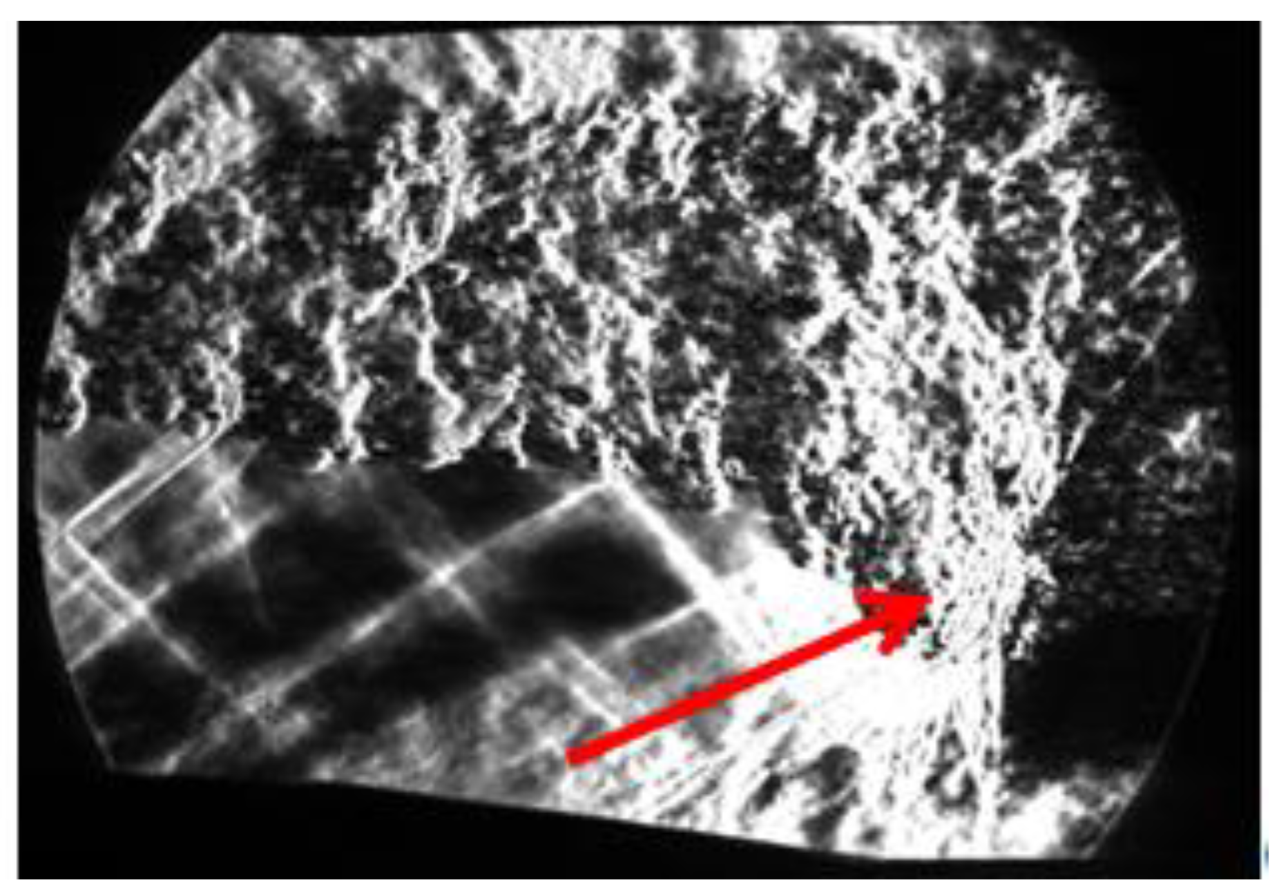
3.3. Dynamics of Ignition and Motion of the Flame Front

For some of these experiments, the author had access to high-speed video recording by Phantom VEO 410 color camera with a 200 µs exposure and a frame rate of 5 kHz, which made it possible to obtain important new data on ignition dynamics and flame oscillations. When the discharge is turned on in airflow, the discharge has a characteristic color due to the glow of molecular nitrogen N22+. When fuel is supplied, the color of the discharge changes, and a greenish-bluish glow is observed in the wake of the discharge, which is characteristic of the glow of CN molecules. This zone is closed by an area with a bluer color, after which the glow is practically absent (Figure 11). A comparison of high-speed shooting data and pressure made it possible to establish that, in the greenish-bluish glow region, there is practically no pressure rise, and only with the arrival of the blue region to the sensor zone is a pressure rise observed due to intense heat release. Thus, the dynamics of ignition and stabilization of the flame front in the case of 500 Ω turned out to be as follows: after fuel is supplied to the discharge zone, the so-called cold flame is formed in the wake of the discharge, and it takes some time (~1–2 ms) to ignite the first volumes of the mixture treated with plasma. However, these volumes are carried downstream by the flow; ignition (transition to a hot flame) occurs in the third window or downstream, after which the flame front begins to move upstream at a speed of ~100 m/s (relative to the channel), or with an absolute speed (taking into account the supersonic flow with an initial speed of 500 m/s) about 400–600 m/s, i.e., the deflagration mode of flame propagation through the mixture treated with plasma is realized (see Figure 12 or Supplementary Materials Video S2). The boundary between the cold flame and the zone of intense heat release was also fixed using Schlieren visualization (see Figure 13). It is assumed that here fast deflagration or deflagration to detonation transition takes place. Hot air–fuel mixture processed by plasma is flowing down. The speed of the mixture is high, but due to the temperature of the plasma, the Mach number is lower (the expected value is 0.8–1.2). Under such conditions, a fast deflagration takes place after ignition (transition from cold to hot flame for some portion of the mixture) and the flame front moves upstream. A detailed study of this effect is beyond the scope of this article. After the arrival of the flame front to the discharge zone the position of the flame front pulsates with frequencies of 70–400 Hz, depending on the experimental conditions.
With a fixed current limiting mode, a lower oscillation frequency corresponds to a higher fuel consumption. Oscillations occur similarly to the mechanism described in [34]: the flame front reaches the plasma region, burning out the already formed mixture and reducing the length (power) of the discharge. Because both elements of maintaining combustion (the presence of a mixture and the discharge power) decreased, the flame weakens and is blown down by the flow. This leads to the production of a new volume of the mixture and the restoration of the discharge length and power. Thereafter the flame front again reaches the plasma region and the process is repeated. The resulting oscillation frequencies are presented in Table 2. In the case of 750 Ω, the oscillations had an insignificant amplitude, compared with the variant with the maximum current at 500 Ω.

4. Conclusions

In this work, a new geometry of pylon equipped with long electrodes was proposed, experimentally tested, and optimized. The modes of operation were also described.
It has been shown that one long loop could ignite fuel in supersonic flow and provide flameholding in conditions without flow separation, but it must be long and powerful enough (~40 mm long loop (~80 mm plasma filament) with 4 kW power during combustion). At the same time, a significant reduction in power requirements was achieved relative to previous configurations: 3–5 kW instead of 10–18 kW used in other schemes [5,20]; the obtained pressure distribution is the same or better than that obtained previously. The increase in pressure is facilitated by improved mixing due to the remoteness of fuel injection from the walls of the channel. It is also important to note that the power impact to discharge is much lower than release during the complete combustion of 1 g/s of ethylene (48 kW).
Stabilization of the flame front was performed in the flow away from the wall to prevent or reduce the near-wall separation zone, and the pylon was made in a streamlined shape and did not have a stabilizing effect. Thus, this work shows the ability of plasma to ignite a mixture in a supersonic flow in the most difficult conditions without other flame stabilizers and could be used as an emergency tool for the start/restart of a scramjet engine. It is noteworthy that the spatiotemporal visualization of the ignition delay in the case of plasma-assisted combustion in a supersonic flow presented in the paper was obtained for the first time. However, it is important to note that the ignition delay time is 1–2 ms, and during this time the mixture flows downstream a considerable distance. Further research may be aimed at reducing the ignition delay time.
It was shown that in the presented configuration, ignition occurs at a considerable distance from the pylon, close to the exit from the combustion chamber; and, depending on the pylon version (or discharge configuration), the position of the flame front stabilization could be located in the downstream part of the channel, or the area near discharge. For the latter configuration (ver.b) with 500 Ω ballast resistance, the flame front moves upstream to the discharge region along the mixed volume of the air-fuel mixture treated with plasma. This allows us to speak about the possibility of creating short combustion chambers. To reduce the fluctuations in the flame front in subsequent studies, we can investigate the use of a discharge with controlled power.
The proposed configuration allows the scaling of the combustion chamber by delivering fuel and discharge to the core of the flow in comparison to the classical chamber with a cavity. In addition, such a solution could be used to design less thermally loaded combustion chambers, when the flow near the wall will remain cold.

Supplementary Materials

The following supporting information can be downloaded at: https://www.mdpi.com/article/10.3390/aerospace10030204/s1, Video S1: Schlieren visualization of plasma-assisted combustion, Video S2: High-speed video of ignition and flameholding by discharge.

Funding

This work was performed within State Assignment No. 075-01056-22-00 by the Ministry of Science and Higher Education of the Russian Federation.

Data Availability Statement

Data are available upon reasonable request.

Acknowledgments

The authors thank engineer K.V. Savelkin and jr. researcher N.A. Kolosov for their help in the preparation and performing of the experiments.

Conflicts of Interest

The author declares no conflict of interest.

References

  1. Liu, Q.; Baccarella, D.; Lee, T. Review of Combustion Stabilization for Hypersonic Airbreathing Propulsion. Prog. Aerosp. Sci. 2020, 119, 100636. [Google Scholar] [CrossRef]
  2. Huang, W.; Du, Z.B.; Yan, L.; Xia, Z. xun Supersonic Mixing in Airbreathing Propulsion Systems for Hypersonic Flights. Prog. Aerosp. Sci. 2019, 109, 100545. [Google Scholar] [CrossRef]
  3. Cai, Z.; Wang, T.; Sun, M. Review of Cavity Ignition in Supersonic Flows. Acta Astronaut. 2019, 165, 268–286. [Google Scholar] [CrossRef]
  4. Leonov, S. Electrically Driven Supersonic Combustion. Energies 2018, 11, 1733. [Google Scholar] [CrossRef] [Green Version]
  5. Firsov, A.; Savelkin, K.V.; Yarantsev, D.A.; Leonov, S.B. Plasma-Enhanced Mixing and Flameholding in Supersonic Flow. Philos. Trans. R. Soc. A Math. Phys. Eng. Sci. 2015, 373, 20140337. [Google Scholar] [CrossRef] [Green Version]
  6. Shibkov, V.M.; Shibkova, L.V.; Kopyl, P.V.; Logunov, A.A. Stabilization of Supersonic Combustion of Propane in an Expanding Aerodynamic Channel with the Use of Low-Temperature Plasma. High Temp. 2019, 57, 164–176. [Google Scholar] [CrossRef]
  7. Goldfeld, M. The Heat Flux Research in Hydrogen Supersonic Combustor at Mach Number of 4. Int. J. Hydrogen Energy 2021, 46, 13365–13376. [Google Scholar] [CrossRef]
  8. Jia, D.; Pan, Y.; Wang, N.; Liu, C.; Yang, K. Combustion Modes and Unsteady Characteristics during the Condition Transition of a Scramjet Combustor. Energies 2021, 14, 2522. [Google Scholar] [CrossRef]
  9. He, Z.; Wang, H.; Li, F.; Tian, Y.; Wan, M.; Zhu, J. Effect of Fuel-Injection Distance and Cavity Rear-Wall Height on the Flameholding Characteristics in a Mach 2.52 Supersonic Flow. Aerospace 2022, 9, 566. [Google Scholar] [CrossRef]
  10. Goldfeld, M.A.; Starov, A.V. Determination of the Fuel Concentration Distribution in a Supersonic Combustion Chamber. Combust. Explos. Shock. Waves 2019, 55, 274–281. [Google Scholar] [CrossRef]
  11. Jin, Y.; Dou, S.; Yang, Q.; Xu, X.; Fu, Q.; Pan, L. Performance Characteristics of a Scramjet Engine Using JP-10 Fuel Containing Aluminum Nanoparticles. Acta Astronaut. 2021, 185, 70–77. [Google Scholar] [CrossRef]
  12. Yarantsev, D.A.; Fisov, A.A.; Dolgov, E.V.; Savelkin, K.V.; Talyzin, V.A.; Nikolaev, A.A.; Voloshenko, O.V. Ignition of Gaseous and Liquid Hydrocarbon Fuel in Supersonic Flow by Means of Plasma Generator. J. Phys. Conf. Ser. 2019, 1394, 012014. [Google Scholar] [CrossRef]
  13. Li, X.; Lei, Q.; Zhao, X.; Fan, W.; Chen, S.; Chen, L.; Tian, Y.; Zhou, Q. Combustion Characteristics of a Supersonic Combustor with a Large Cavity Length-to-Depth Ratio. Aerospace 2022, 9, 214. [Google Scholar] [CrossRef]
  14. Tang, T.; Zhao, G.; Wang, H.; Sun, M.; Wang, Z. Effects of Cavity Parameters on Flame Flashback Phenomenon in a Supersonic Crossflow with a Cavity Flameholder. J. Proc. Inst. Mech. Eng. G J. Aerosp. Eng. 2022. [Google Scholar] [CrossRef]
  15. Efimov, A.V.; Firsov, A.A.; Kolosov, N.S.; Leonov, S.B. Characterization of Electric Discharge Collocated with Gas Jet in Supersonic Airflow. Plasma Sources Sci. Technol. 2020, 29, 07LT01. [Google Scholar] [CrossRef]
  16. Shibkov, V.M.; Kornev, K.N.; Logunov, A.A.; Nesterenko, Y.K. Electron Density and Temperature in a Transverse–Longitudinal Discharge Plasma in High-Speed Airflows. Plasma Phys. Rep. 2022, 48, 806–811. [Google Scholar] [CrossRef]
  17. Firsov, A.; Bityurin, V.; Tarasov, D.; Dobrovolskaya, A.; Troshkin, R.; Bocharov, A. Longitudinal DC Discharge in a Supersonic Flow: Numerical Simulation and Experiment. Energies 2022, 15, 7015. [Google Scholar] [CrossRef]
  18. Andrews, P.; Lax, P.; Leonov, S. Triggering Shock Wave Positions by Patterned Energy Deposition. Energies 2022, 15, 7104. [Google Scholar] [CrossRef]
  19. Filimonova, E.A.; Dobrovolskaya, A.S.; Bocharov, A.N.; Bityurin, V.A.; Naidis, G.V. Formation of Combustion Wave in Lean Propane-Air Mixture with a Non-Uniform Chemical Reactivity Initiated by Nanosecond Streamer Discharges in the HCCI Engine. Combust. Flame 2020, 215, 401–416. [Google Scholar] [CrossRef]
  20. Leonov, S.B.; Elliott, S.; Carter, C.; Houpt, A.; Lax, P.; Ombrello, T. Modes of Plasma-Stabilized Combustion in Cavity-Based M = 2 Configuration. Exp. Therm. Fluid Sci. 2021, 124, 110355. [Google Scholar] [CrossRef]
  21. Feng, R.; Li, J.; Wu, Y.; Zhu, J.; Song, X.; Li, X. Experimental Investigation on Gliding Arc Discharge Plasma Ignition and Flame Stabilization in Scramjet Combustor. Aerosp. Sci. Technol. 2018, 79, 145–153. [Google Scholar] [CrossRef]
  22. Feng, R.; Sun, M.; Wang, H.; Huang, Y.; Tian, Y.; Wang, C.; Liu, X.; Zhu, J.; Wang, Z. Experimental Investigation of Flameholding in a Cavity-Based Scramjet Combustor by a Multi-Channel Gliding Arc. Aerosp. Sci. Technol. 2022, 121, 107381. [Google Scholar] [CrossRef]
  23. Kim, C.H.; Jeung, I.S. Forced Combustion Characteristics Related to Different Injection Locations in Unheated Supersonic Flow. Energies 2019, 12, 1746. [Google Scholar] [CrossRef] [Green Version]
  24. Leonov, S.; Houpt, A.; Elliott, S.; Hedlund, B. Ethylene Ignition and Flameholding by Electrical Discharge in Supersonic Combustor. J. Propuls. Power 2018, 34, 499–509. [Google Scholar] [CrossRef]
  25. Firsov, A.A.; Efimov, A.V.; Kolosov, N.S.; Moralev, I.A.; Leonov, S.B. Intensification of Mixing of Fuel with Supersonic Air Flow When Injection and Electric Discharge Are Combined. J. Phys. Conf. Ser. 2021, 2100, 012007. [Google Scholar] [CrossRef]
  26. Vishwakarma, M.; Vaidyanathan, A. Experimental Study of Mixing Enhancement Using Pylon in Supersonic Flow. Acta Astronaut. 2016, 118, 21–32. [Google Scholar] [CrossRef]
  27. Inshakov, S.I.; Skvortsov, V.V.; Rozhkov, A.F.; Shakhatov, V.A.; Inshakov, I.S.; Uspensky, A.A.; Urusov, A.Y. Spectroscopic Studies of Longitudinal Discharges in a Supersonic Air Flow during the Injection of Propane, Ethylene, and Oxygen into the Discharge Zone. High Temp. 2019, 57, 798–807. [Google Scholar] [CrossRef]
  28. Firsov, A.A.; Dolgov, E.V.; Kolosov, N.S.; Yarantsev, D.A. CFD Analysis of Pylon Equipped by Plasma Module for Combustion in Supersonic Airflow. J. Phys. Conf. Ser. 2020, 1698, 012014. [Google Scholar] [CrossRef]
  29. Firsov, A.A.; Kolosov, N.S. Combustion in a Supersonic Flow Using a Pylon Equipped with a Plasma Actuator. J. Phys. Conf. Ser. 2021, 2100, 012017. [Google Scholar] [CrossRef]
  30. Logunov, A.A.; Kornev, K.N.; Shibkova, L.V.; Shibkov, V.M. Influence of the Interelectrode Gap on the Main Characteristics of a Pulsating Transverse-Longitudinal Discharge in High-Velocity Multicomponent Gas Flows. High Temp. 2021, 59, 19–26. [Google Scholar] [CrossRef]
  31. Firsov, A.A.; Dolgov, E.V.; Leonov, S.B. Optimization of the Plasma System for the Ignition of Ethylene in a Supersonic Flow. Vestn. Obedin. Inst. Vysok. Temp. 2018, 1, 13–18. [Google Scholar] [CrossRef]
  32. Shibkov, V.M.; Shibkova, L.V.; Logunov, A.A. Effect of the Air Flow Velocity on the Characteristics of a Pulsating Discharge Produced by a DC Power Source. Plasma Phys. Rep. 2018, 44, 754–765. [Google Scholar] [CrossRef]
  33. Houpt, A.; Hedlund, B.; Leonov, S.; Ombrello, T.; Carter, C. Quasi-DC Electrical Discharge Characterization in a Supersonic Flow. Exp. Fluids 2017, 58, 25. [Google Scholar] [CrossRef]
  34. Savelkin, K.V.; Yarantsev, D.A.; Adamovich, I.V.; Leonov, S.B. Ignition and Flameholding in a Supersonic Combustor by an Electrical Discharge Combined with a Fuel Injector. Combust. Flame 2015, 162, 825–835. [Google Scholar] [CrossRef]
Figure 1. Test section with pylon installed.
Aerospace 10 00204 g001
Figure 2. Principal view of the pylon, equipped with fuel injectors and a plasma module: (a) Ver.a—straight electrodes; (b) Ver.b—angled ends of the electrodes (image after tests).
Aerospace 10 00204 g002
Figure 3. Static pressure distribution for pylon ver.a in the case of ballast resistance of (a) 750 and 1 kΩ; and (b) 500 Ω. The pylon is located between 50 and 80 mm, and the ends of the electrodes are located at 110 mm.
Aerospace 10 00204 g003
Figure 4. Schlieren visualization of ethylene combustion when testing pylon ver.a: (a,b) Current 7.5 A, visible variable discharge length; (c) Breakdown on the pylon body.
Aerospace 10 00204 g004
Figure 5. Oscillogram of discharge voltage during flame pulsations.
Aerospace 10 00204 g005
Figure 6. Re-breakdown process visualization (0, 5, and 15 µs) (a); Oscillograms of voltage and current of Q-DC discharge without fuel at 500 Ω (b).
Aerospace 10 00204 g006
Figure 7. Statistical data about discharge voltage and re-breakdown period for ver.b configuration.
Aerospace 10 00204 g007
Figure 8. Static pressure distribution for pylon ver.b in the case of ballast resistance of (a) 750 and 1 kΩ; and (b) 500 Ω. The pylon is located between 50 and 80 mm, and the ends of the electrodes are located at 120 mm.
Aerospace 10 00204 g008
Figure 9. Schlieren visualization of the flow during the operation of the discharge (top) and during plasma-assisted combustion (bottom).
Aerospace 10 00204 g009
Figure 10. Oscillogram of the current and voltage of the discharge, as well as the pressure in the region of the flame front.
Aerospace 10 00204 g010
Figure 11. Visualization of the experiment using Phantom VEO 410, top image—discharge into supersonic airflow and bottom image—combustion: 1—plasma region, 2—«cold» flame, 3—hot flame.
Aerospace 10 00204 g011
Figure 12. Dynamics of the flame front after ignition for 500 Ω case.
Aerospace 10 00204 g012
Figure 13. The transition between «cold» and hot flame (the area is shown by an arrow) obtained by Schlieren visualization in the second window.
Aerospace 10 00204 g013
Table 1. Typical electrical characteristics of the discharge in the flow behind the pylon without fuel supply.
Rbal, ΩAverage Current, A
(Ver.a, No Fuel)
Average Current, A
(Ver.b, No Fuel)
10003.202.70
7504.753.96
5007.205.50
Table 2. Frequency (Hz) of flame front oscillations.
Fuel MFR
(g/s)
0.50.7511.5234
Case
750 Ohm--256204968370
500 Ohm-400345313294182188
Disclaimer/Publisher’s Note: The statements, opinions and data contained in all publications are solely those of the individual author(s) and contributor(s) and not of MDPI and/or the editor(s). MDPI and/or the editor(s) disclaim responsibility for any injury to people or property resulting from any ideas, methods, instructions or products referred to in the content.

