Article

Micro Turbojet Engine Nozzle Ejector Impact on the Acoustic Emission, Thrust Force and Fuel Consumption Analysis

by
Grigore Cican
1,*,
Tiberius-Florian Frigioescu
2,
Daniel-Eugeniu Crunteanu
1 and
Laurentiu Cristea
2
1
Faculty of Aerospace Engineering, University Politehnica of Bucharest, 1-7 Polizu Street, 1, 011061 Bucharest, Romania
2
National Research and Development Institute for Gas Turbines COMOTI, 061126 Bucharest, Romania
*
Author to whom correspondence should be addressed.
Aerospace 2023, 10(2), 162; https://doi.org/10.3390/aerospace10020162
Submission received: 30 November 2022 / Revised: 6 February 2023 / Accepted: 7 February 2023 / Published: 10 February 2023
(This article belongs to the Special Issue Aeroacoustics and Noise Mitigation)

Abstract

:
This paper explores the implementation of an ejector to a micro turbojet engine and analysis of the advantages in terms of acoustic and thrust/fuel consumption. Starting with the analytical equations and a series of numerical simulations, the optimal ejector geometry for maximum thrust was obtained. The ejector was manufactured and integrated with the Jet Cat P80 micro turbo engine for testing. The purpose of this article is to report on an improved geometry that results in no significant increase in the frontal area of the turbo engine, which could increase drag. The tests were completed using various functioning regimes, namely idle, cruise and maximum. For each of them, a comparative analysis between engine parameters with and without an ejector was performed. During the experiments, it was observed that, when the ejector was used, the thrust increased for each regime, and the specific consumption decreased for all regimes. The stability of the engine was tested in transient regimes by performing a sudden acceleration sequence, and one carried out the operating line and the modification of temperature values in front of the turbine for both configurations. For each regime, the acoustic noise was monitored at a few points that were different distances from the nozzle, and a decrease was identified when the ejector was used. The advantages of using the ejector on the Jet Cat P80 turbo jet engine are an increased thrust, a lower specific consumption and a reduced noise level, and at the same time, the integrity of the engine in stable operational states and transient operating regimes is not affected.

1. Introduction

Chemical and noise pollution [1,2] are the most significant problems for mankind. The transportation sector is one of the most significant chemical and noise pollution sources, and an important element of it is represented by aviation [3,4]. The burning of hydrocarbons in turbo engines is the source of chemical pollution, and the take-off and landing phases of an aircraft are the main noise sources in aviation. The engines of commercial airplanes are an important noise source, and the jet is the main noise source of turbojet engines [5,6].
In the last few years, there has been increasing interest in finding available solutions to stop the effects of chemical and noise pollution on the environment and human beings. Biofuel and alternative fuel [7,8,9], hydrogen [10,11], electrical propulsion [12], etc., are common solutions to reduce or eliminate chemical pollution [13].
In order to reduce aircraft noise pollution, chevrons [14,15], acoustic liners, [16] performance engine design, [17,18] etc., are common solutions to reduce the noise pollution of jet engines.
Jet ejectors are conceptual and construction solutions that are able to reduce the fuel consumption and noise pressure level of a turbo jet engine. A jet ejector is a component where a fluid is thrown out through a nozzle exit into an empty, mainly cylindrical shape and is also used to employ a high-velocity primary jet that produces a derived secondary one through momentum and energy transfer [19].
Jet ejectors have a simple geometry and no moving components, and their functioning does not involve electrical devices or rotational mechanical components driven by a shaft; their simplicity reduces the total equipment mass and increases reliability.
In an article from 1950, Keenan and Neumann [20] studied ejector problems from their theoretical and experimental aspects. Ejectors are extensively used in power plant applications, aerospace propulsion and the refrigeration industry due to the above-mentioned aspects [21,22].
In aviation, ejectors can be used in both military and civil aircraft turbo engines for the purpose of increasing the thrust or decreasing the fuel consumption and reducing the jet noise. Douglas DC-8 commercial airplanes propelled by the Rolls-Royce Conway engine were equipped with a nozzle jet ejector. This ejector was used on the DC-8s powered by JT3C, JT4A or RR Conway engines. Usually lengthened for take-off and landing, the ejector was withdrawn during flight after take-off because it was no longer used and produced drag at higher speeds; then, it was lengthened again during the descent and approach phase. This “ejector” claimed to reduce the sound level by 3–4 decibels [23].
SR-71 Black Bird military aircraft were propelled by J-58 turbo engines, which had an ejector system [24]. The detonation engine [25], ram jet engine [26], rocket engine [27] and special military applications [28] are other propulsion systems that can use the jet ejector. A subsonic, mixed-flow turbofan installation and a cylindrical shroud ejector were investigated numerically in [29]. The study aimed to gain an understanding of secondary flow entrainment and thrust enhancement, ejector performance trends, the possibility of extracting installation boundary layers with ejector pumping and estimating drag reductions. An arrangement with incomplete mixing showed an important gross thrust increase of 24% stationary at sea level and 18% at Mach 0.6 to 0.8 at altitude.
For large aviation turbo engines, it is quite inconvenient to implement an ejector-type system because of the dimensions and the control system, since it is efficient only at low flight speeds. For micromotors that can be used in drones and unmanned aircraft systems, an ejector may be a solution because there is a concern about equipping micromotors with ejectors that do not make a lot of noise and are resistant to impingement, which has advantages in terms of increasing thrust, lowering the specific consumption and reducing noise.
The studies in specialized literature are quite poor regarding the use of ejectors on aviation micromotors used on drones.
A numerical simulation and the projecting of very small turbojet engine ejector nozzles are presented in [30]; they studied the possibility of enhancing thrust up to 9% and significantly reducing exhaust gas temperatures with the ejector nozzle concept.
This paper presents the implementation of an ejector on a micro turbojet engine.
The proposed solution is a simple one that does not greatly increase the frontal area of the engine in order to avoid high drag, and it was also decided that the ejector should be very simple, easy to make and very light. The advantages in terms of noise level, thrust/fuel consumption and engine stability on transient regimes were analyzed. The purpose of this article is to demonstrate that the use of an ejector nozzle could be a solution to reduce the fuel consumption and acoustic pressure level of micro turbojet engines.
Bourhan et al. presented a wide study of ejector concepts, performance and applications [31].
This paper presents the implementation of an ejector to a micro turbojet engine and analysis of the advantages in terms of acoustic and thrust/fuel consumption.

2. Materials and Methods

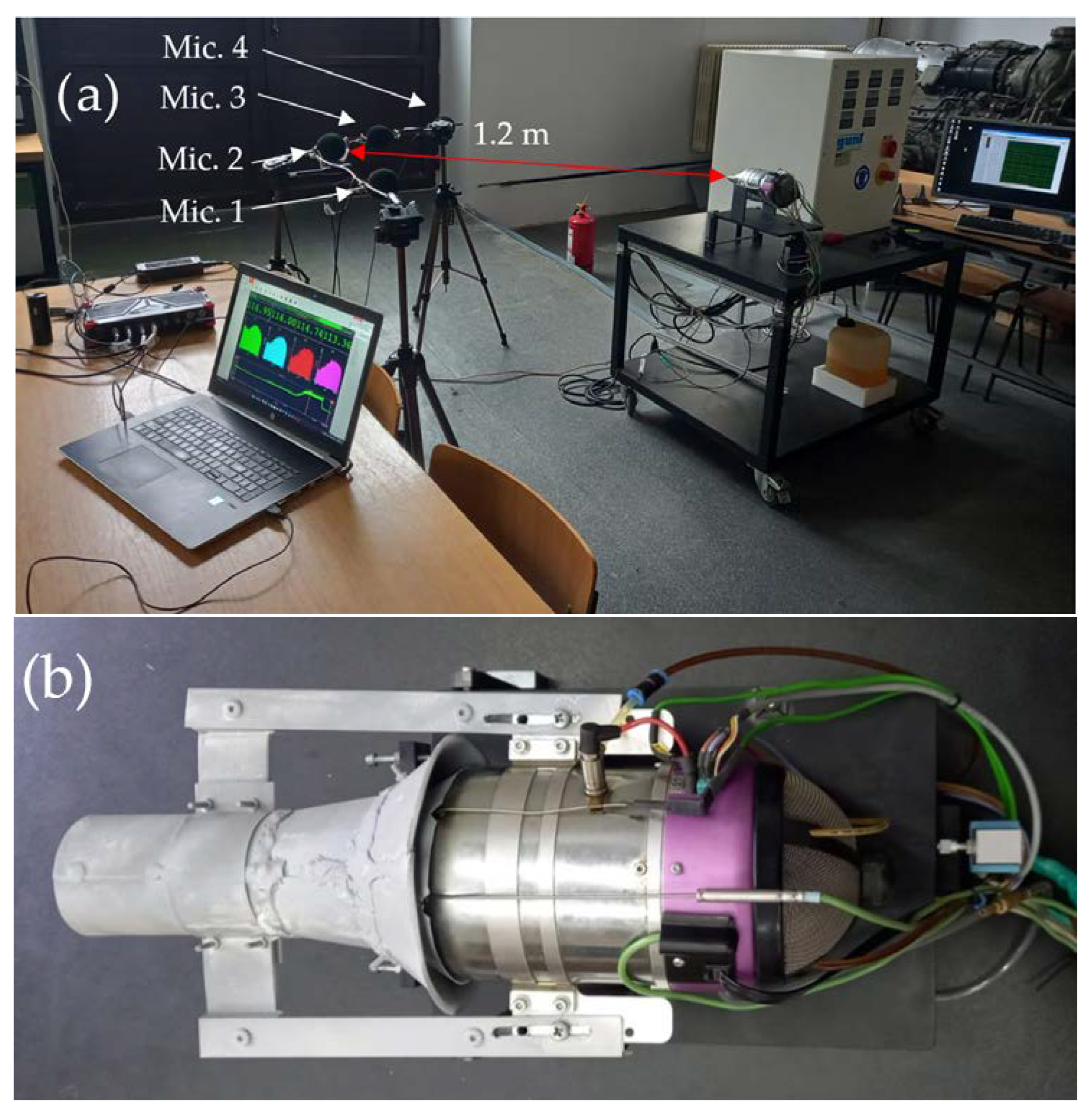
2.1. Experimental Test Bench

The experiments were performed on the Jet CAT P80 micro turbojet engine, which is housed in a laboratory of the Faculty of Aerospace Engineering at Bucharest Polytechnical University [32]. A multi-channel acquisition system with a 50.000 S/s per channel sample rate was used for the measurements. As shown in Figure 1, four microphones were positioned radially 1.2 m away from the engine nozzle. Software was used to process the raw signals using a linear amplitude function, RMS, linear weighting, windowing and linear overall averaging with 50% overlapping. A FFT analysis was performed to visualize the signals’ spectral properties, and band-stop filtering was utilized close to the spectral components related to the shaft speed and its harmonics.
The tests were carried out with the base nozzle and the ejector attached to the engine running at three distinct regimes (Regime 1—35,000 RPM, Regime 2—55,000 RPM and Regime 3—110,000 RPM). The measured parameters were averaged over the course of each regime, which involved maintaining a constant speed for 1 min. The temperatures behind the compressor (T2) and in front of the turbine (T3), pressure in the combustion chamber, air flow, fuel consumption (Qc), resulting compressor ratio (Pic) and force (F) were all monitored with the turbo engine instrumentation.

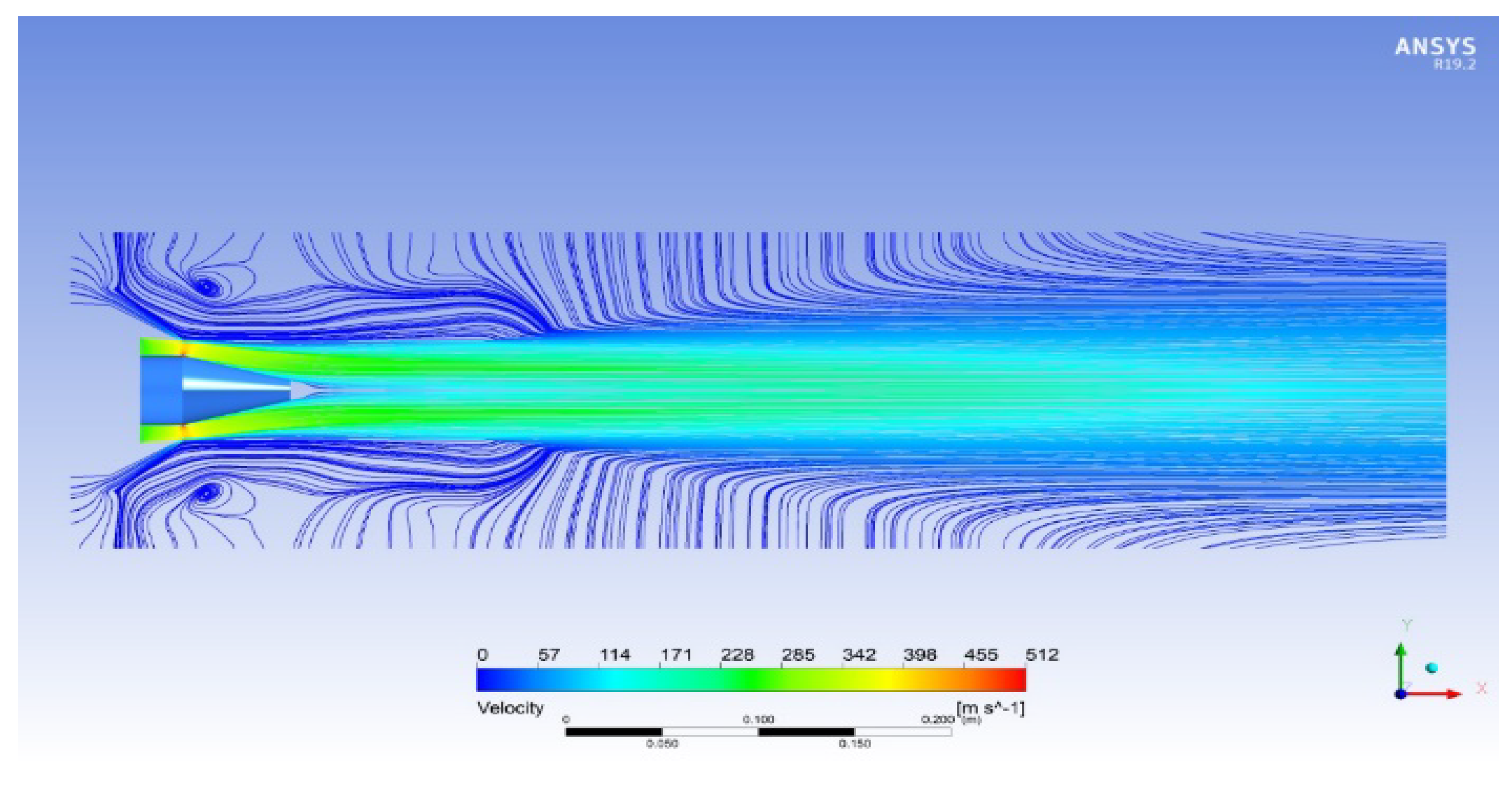
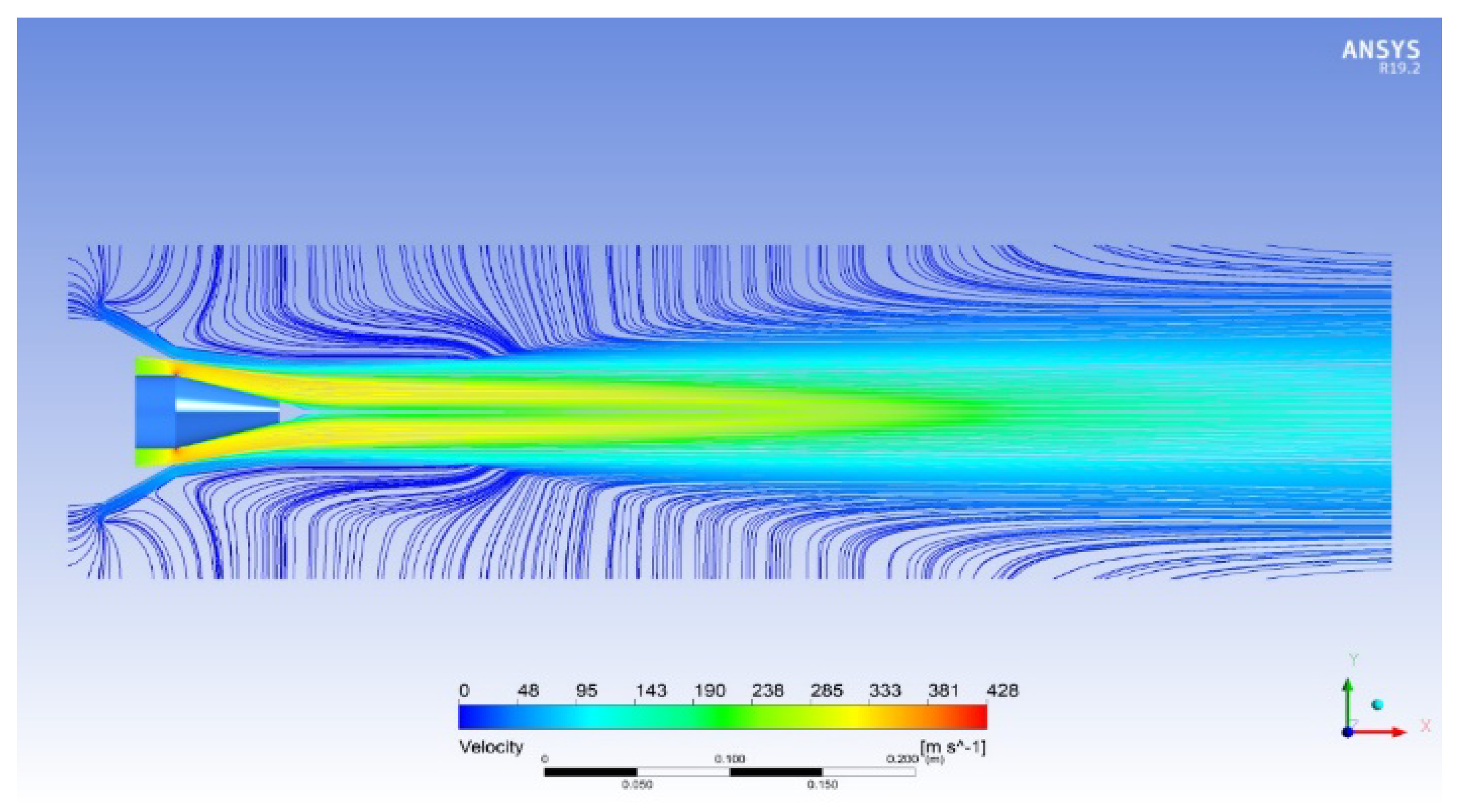
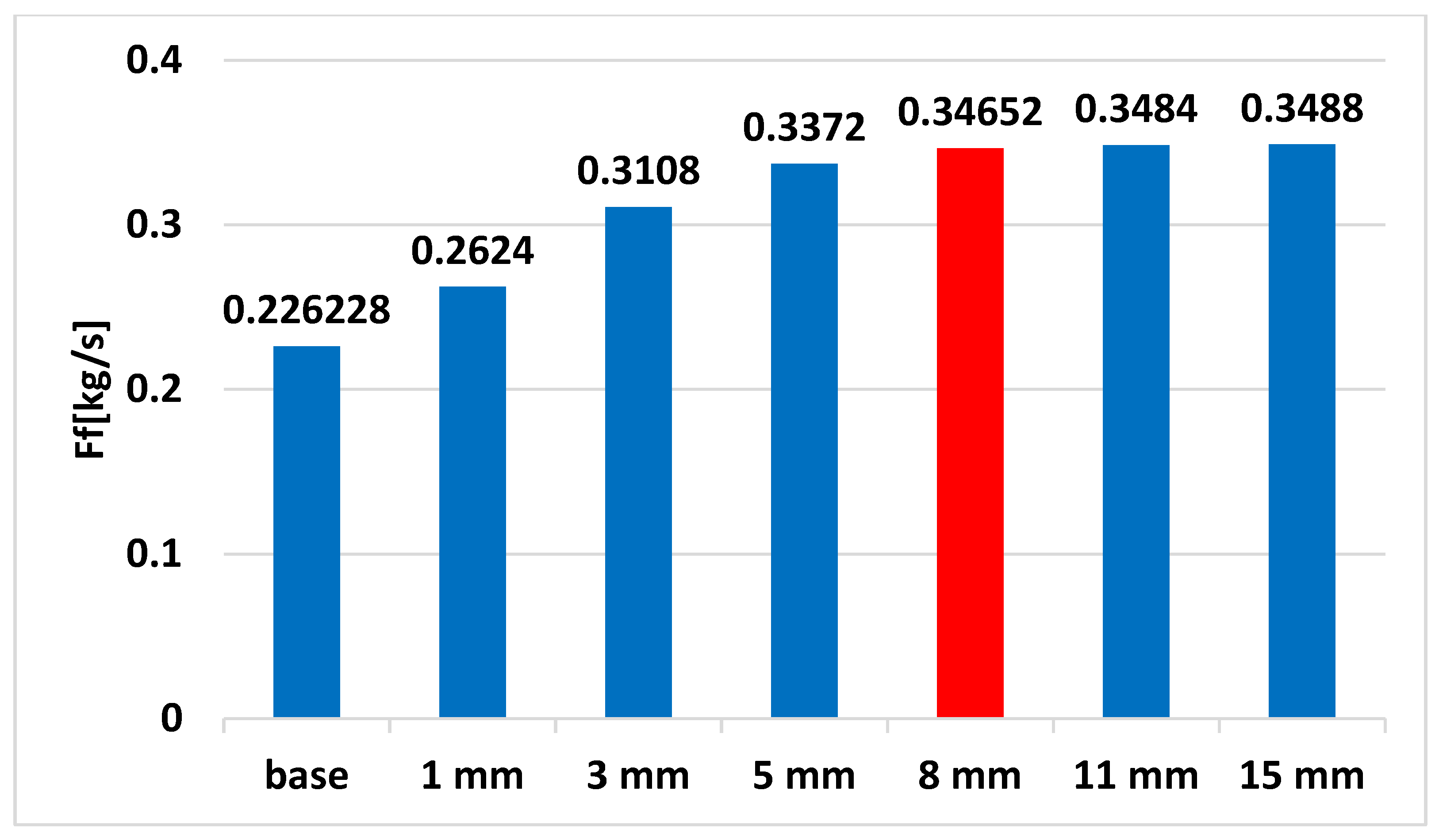
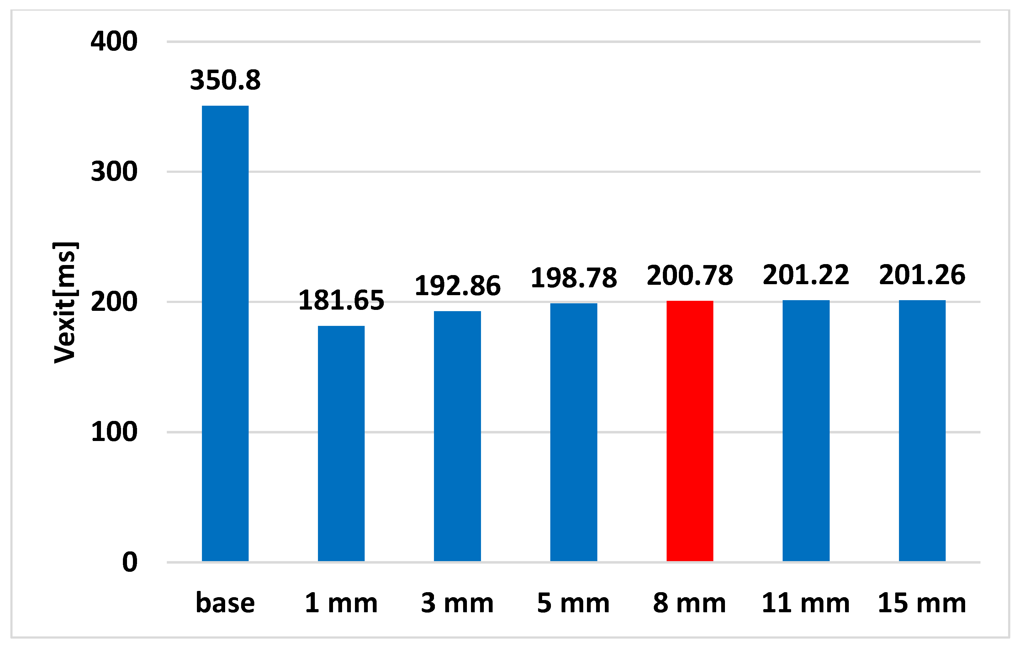
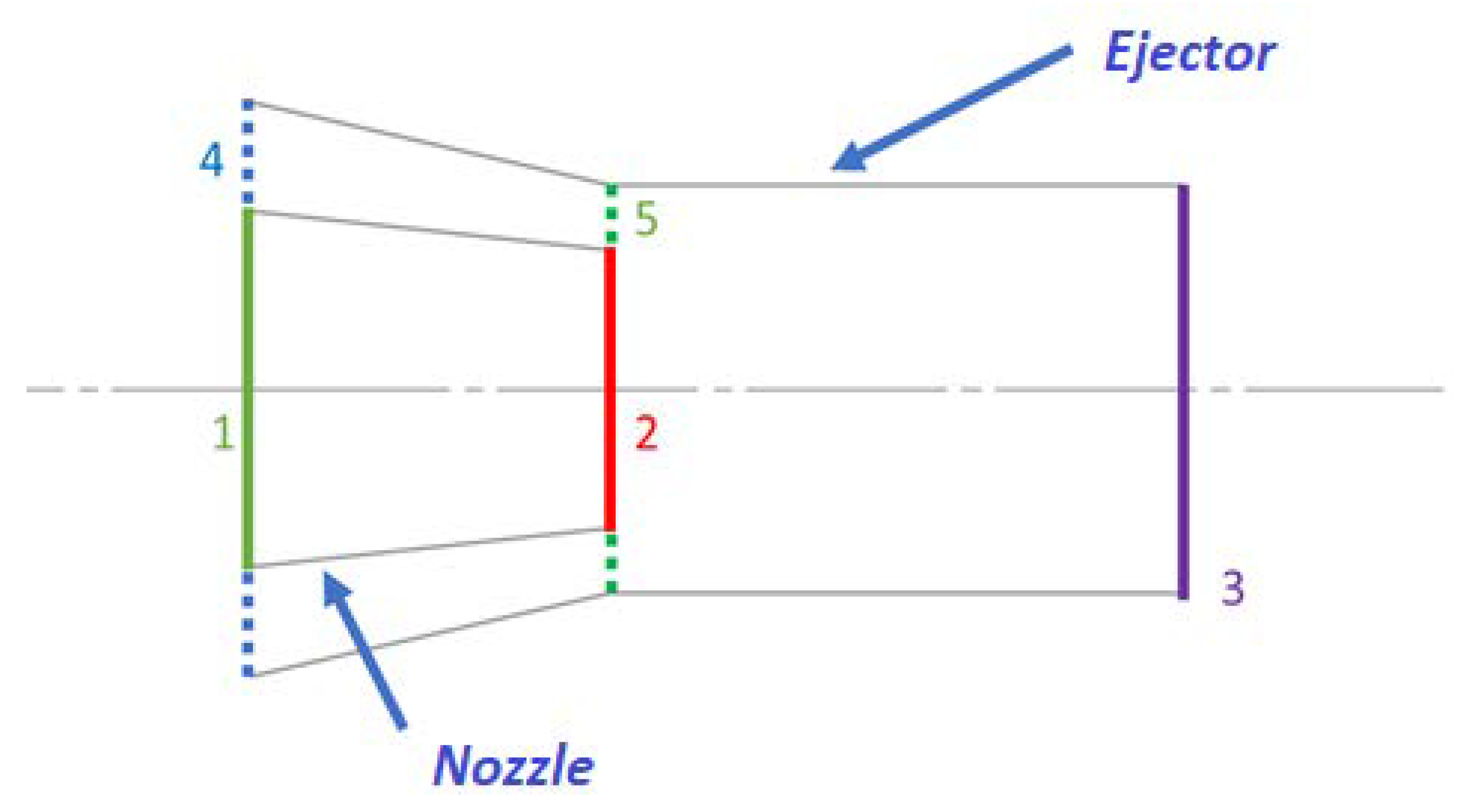
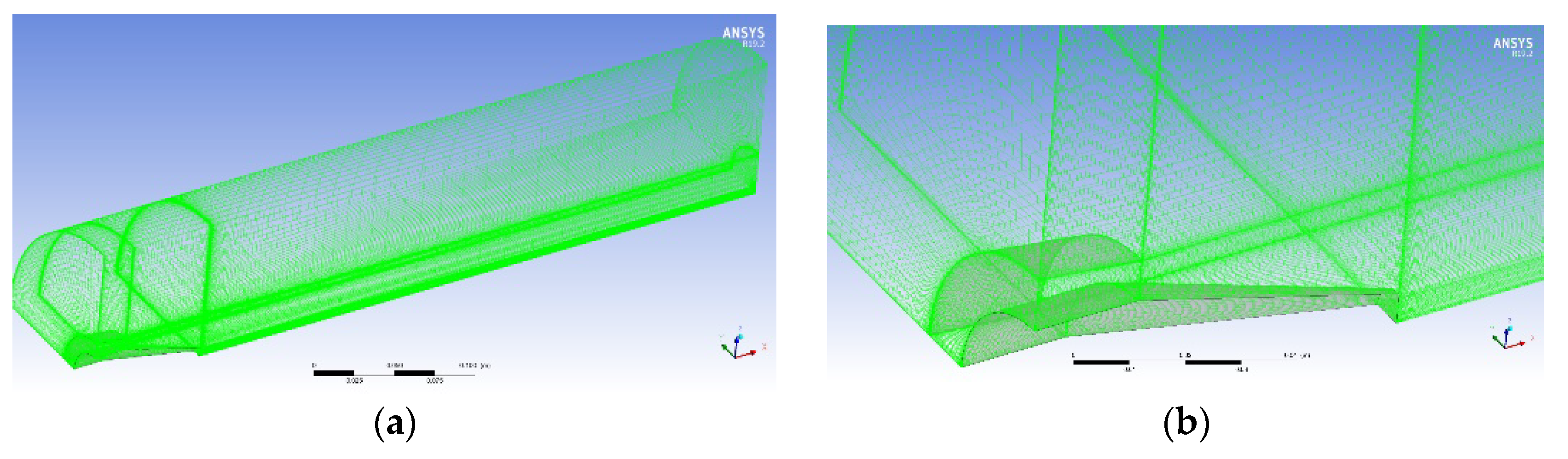
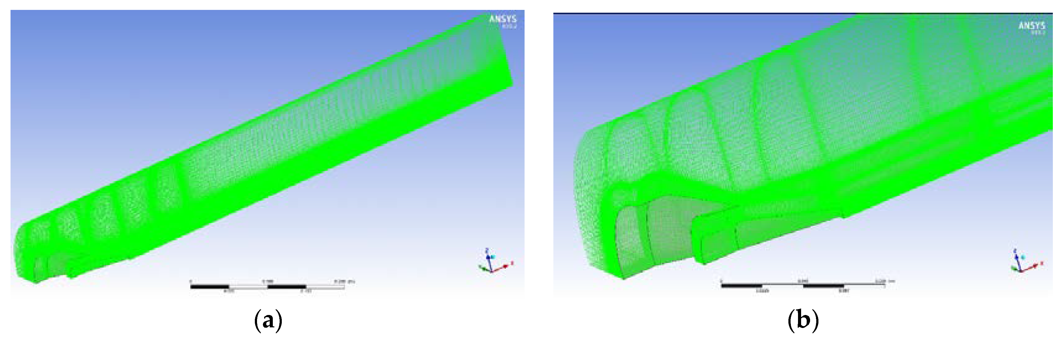
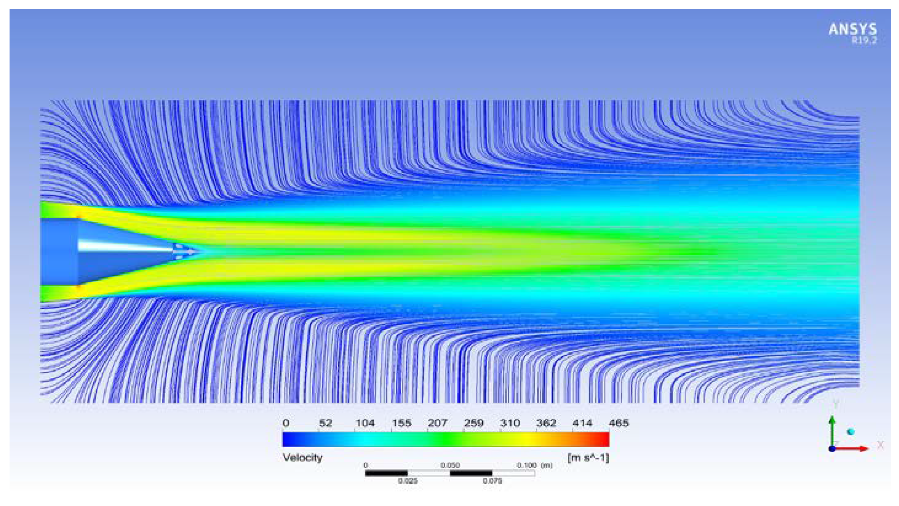
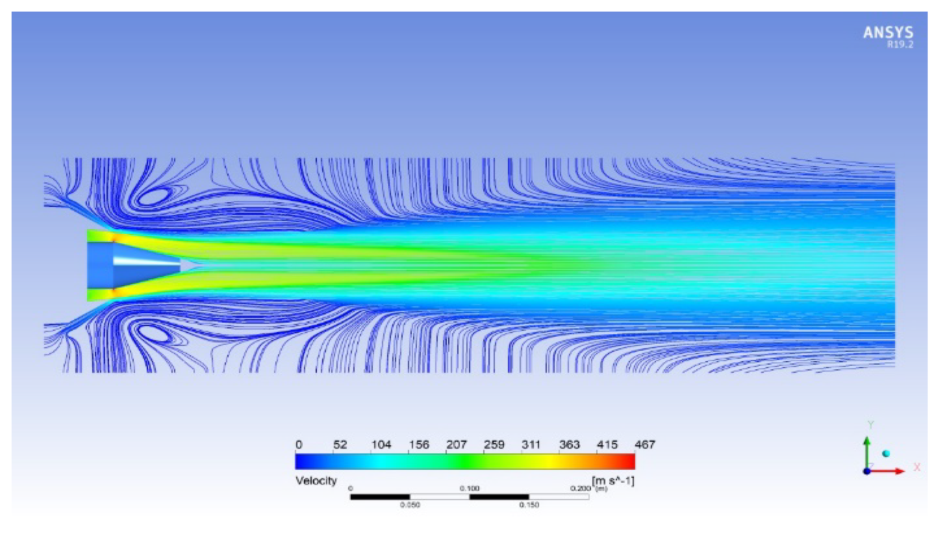
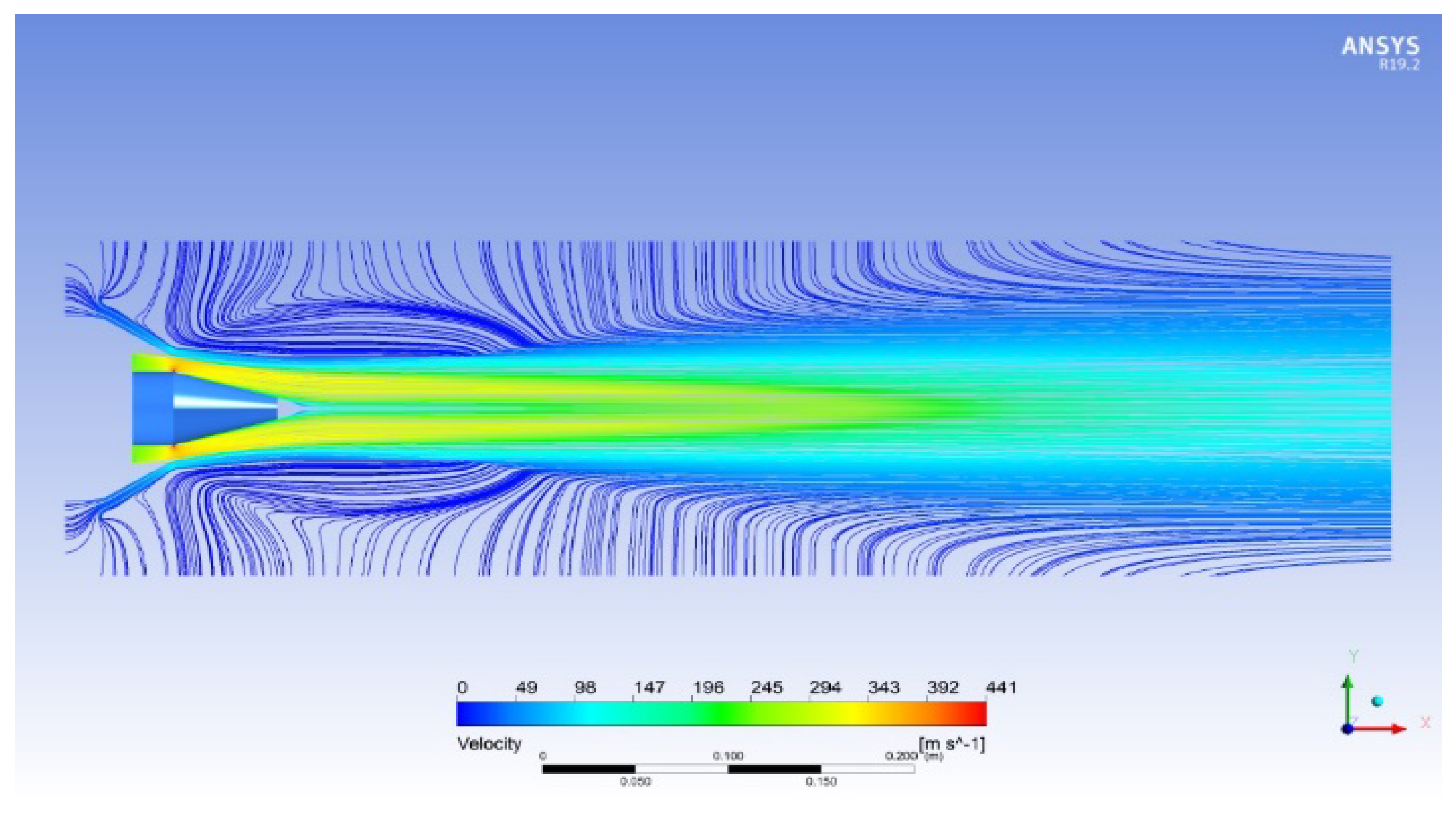
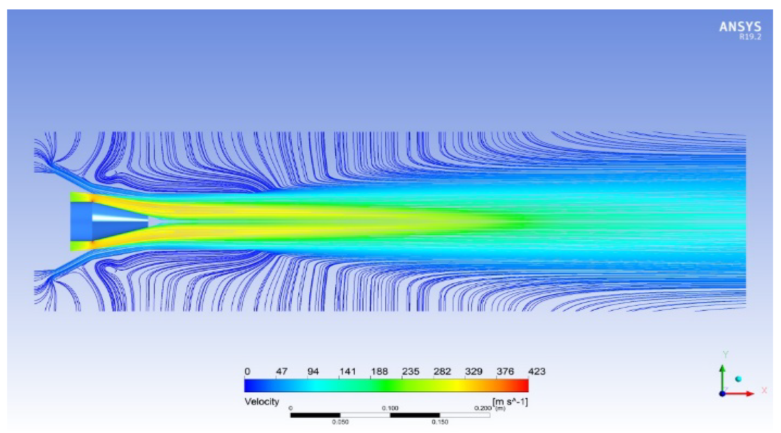
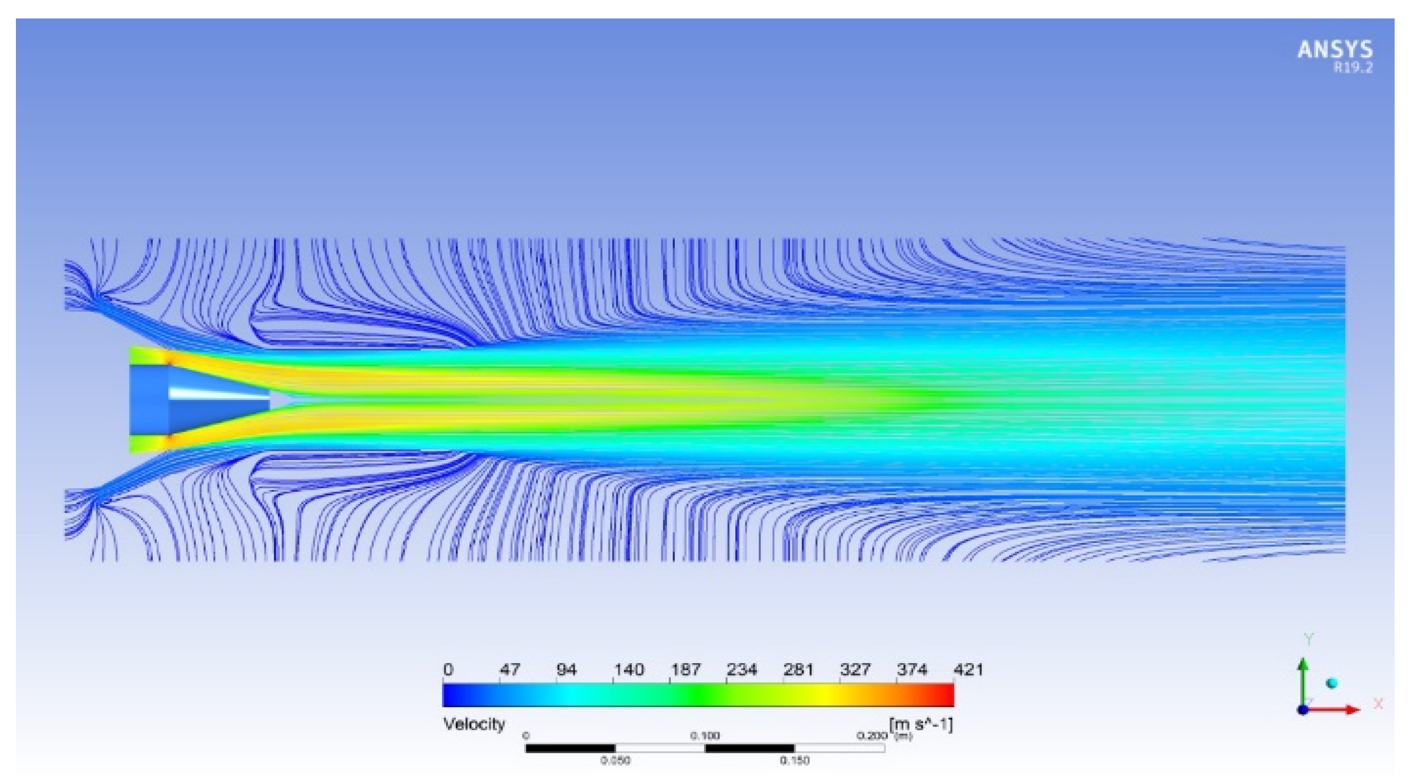
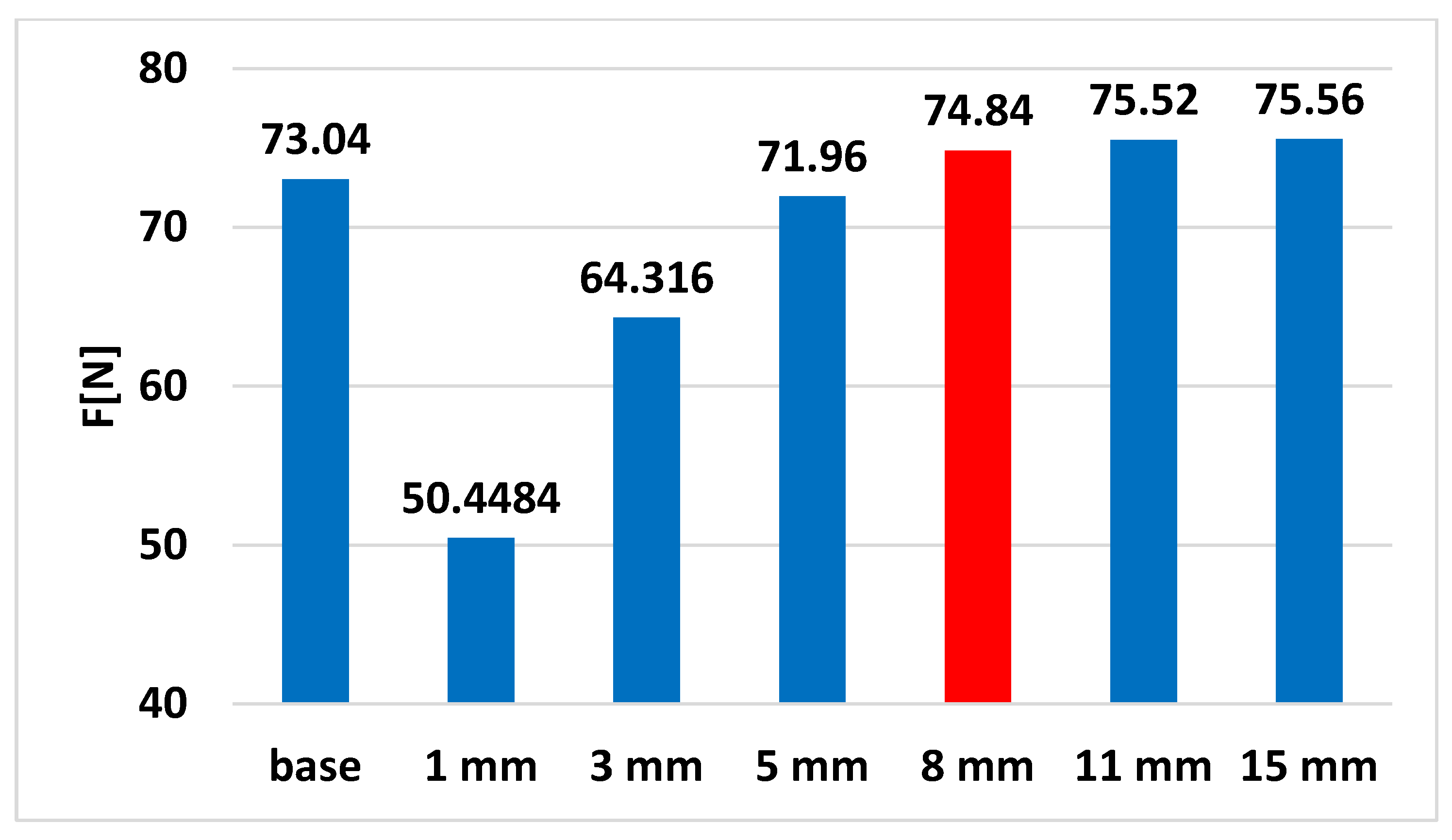
2.2. Design and Optimization of the Ejector Jet

An ejector is a component in which a fluid is ejected through a nozzle exit into an empty, commonly cylindrical body. Based on the shear stresses amongst the moving fluid and the ambient resting fluid, a proportion of the kinetic energy is shifted to the resting fluid. The ejector is used to induce a secondary fluid by momentum and energy transfer from a high-velocity primary jet and, as a consequence, can be used as a pump, blower-augmenter and noise-silencer. When the jet ejector is acting with no modification in pressure, it does not conduct to a pumping effect; however, it does contribute to a thrust increase for the setting-up.
A commonly used jet ejector model is presented schematically in Figure 2.
With this model, the primary jet flow is ejected through the nozzle exit into the ejector, and the velocity is roughly constant, distributed through the whole of the cross-section of the way out of the nozzle. A sub-atmospheric pressure field is obtained, and as a consequence, a secondary flow is created in the rest of the cross-section area of the ejector at the first plane.
The continuity equation, momentum equation, energy equation, thermal equation of state, etc., were applied to the equations governing the thermodynamic system consisting of a nozzle and an injector (for Figure 2).
Applying this system, the engine comes with the gas jet where the following parameters are known: pressure, density, speed, static and total temperature and exhaust area. From the point of view of the flow, the pressure, density and static temperature are known. Imposing a geometry on the ejector means that both the secondary flow area and the ejector exit area are known, and the ejector exit device must achieve a complete expansion; therefore, the ejector exit pressure is also known. The density, velocity and temperature at the exit of the ejector, the absorption pressure of the secondary ambient flow and the flow rate of the secondary air flow remain unknown in this system.
In the first case, an estimated geometry will be required to better understand the actual physical phenomena, and after testing, the above system will be used to find the area of the secondary flow and the area of the ejector exit such that the propulsion force increases.
A turbojet ejector has both advantages and disadvantages because it brings an extra mass of fluid to the system, and at the same time, it slows down as it exits due to the interaction between a high-velocity fluid and a much lower-velocity fluid. Thus, it is necessary to find the optimal value of the areas for which the increase in the mass flow brings a plus to the force even if the evacuation speed decreases.
For the first case, namely the studied case, the following choices were adopted. Given that the area of the exit section of the engine was 1485 × 10−3 m2, it was chosen that the inlet section in the thermodynamic system (ejector) had approximately the same area as that of the engine with an area of 1559 × 10−3 m2. This assumed a ratio of the primary jet section to the ejector inlet section of 0.5 [33]. The ejector must have an inlet. As a border is required for a uniform flow of air and a gradual acceleration of the ambient air fluid velocity from zero velocity to the pressure-corresponding velocity, the secondary flow nozzle must be convergent due to subsonic flow. Thus, an acceptable value of the ejector intake inlet section of 3979 × 10−3 m2 was reached.
In order to optimize the dimensions of the ejector that was built, a series of simulations were performed to choose the best dimensions. In this sense, a series of constraints were imposed on the geometry, such as the length of the ejector and its diameter. A first version of the ejector is shown in Figure 3. In this figure, the dimensions of the nozzle of the Jet Cat P80 micromotor were used, and the ejector was built around it.
With this first scheme of the ejector geometry, a structured mesh was built for the case of the basic nozzle and for 6 cases with dimensions of 1, 3, 5, 8, 11 and 15 mm in section 5 of Figure 3.
In the case of the simulations carried out with ANSYS software, the gas flow rate from the maximum regime at which the micromotor was tested and the total nozzle inlet temperature were used as the input data. The convergence criterion was 10−5 for all residues.
In order to reduce the number of elements and, as a consequence, the running time of the calculator, only a quarter of the domain was taken, being that it was symmetrical.
As this study does not aim to optimize the ejector in terms of the length of the mixing chamber, an indicative length of the ejector was taken so that it would not become too long and would not make the ejector motor assembly difficult. There are several numerical simulation studies in the literature where numerical simulations were performed in order to optimize the ejectors [34,35,36].
For the base case, a structured mesh was created with 575,625 elements with a domain length of 55.2 cm and a domain radius of 24.2 cm, sufficient to not influence the flow as shown in Figure 4.
For the ejector case, a structured mesh with 1,741,480 elements was created as shown in Figure 5.
After carrying out the simulations for all cases, the velocity field with the streamlines is presented. Figure 6 shows the velocity field and streamlines for the base case without the ejector.
Next, Figure 7, Figure 8, Figure 9, Figure 10, Figure 11 and Figure 12 show the results of the numerical simulations for all the cases for which the opening of the working channel section 5 has the value of 1, 3, 5, 8, 11 and 15 mm.
After performing the numerical simulations, the value of the flow force and the velocity data in the exhaust section of the ejector (Section 3) were measured and compared with those for the base case without an ejector as shown in Figure 13, Figure 14 and Figure 15.
It can be seen that, from the 8 mm value, the force starts to increase less and less, and the air flow and the exhaust speed remain almost constant; thus, a value of 8 mm was chosen in order not to greatly increase the frontal area of the motor with the ejector.

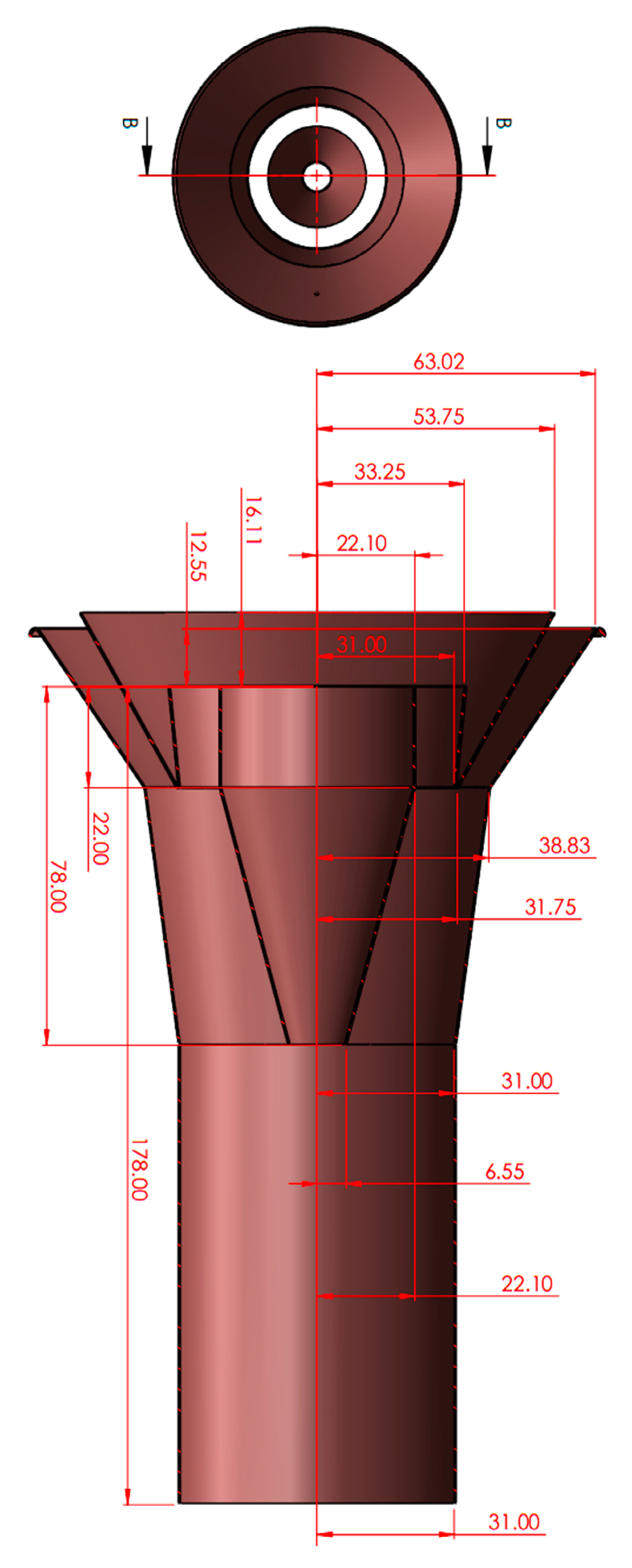
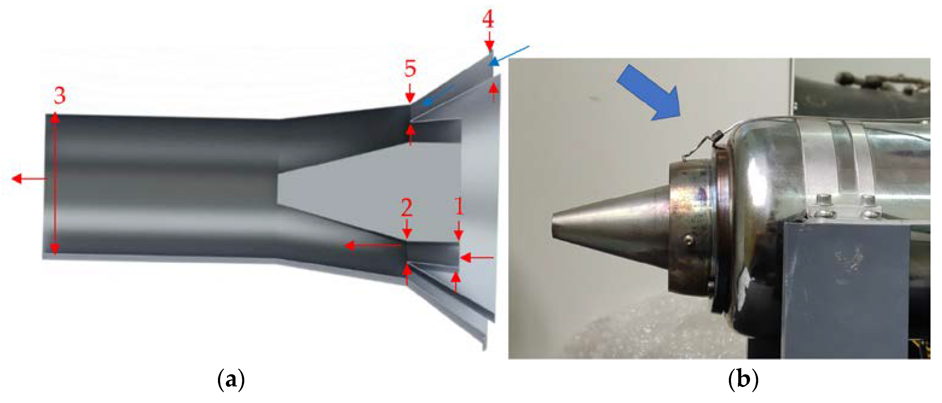
2.3. Ejector Nozzle Manufacturing

Following the above choices, the ejector was drawn in the CAD program SolidWorks. With the inlet and exit sections of the ejector in the previous chapter, it was an assembly of three cones and a cylinder. The first outer cone at the entrance to the ejector has the role of the external intake of the ejector, and the second cone has the role of making the transition between the intake cone and the cylinder. The cylinder is the ejector mixing chamber and, at the same time, the ejector discharge device, in which case the ejector does not have a convergent exhaust nozzle body. The last component is a central cone.
Due to the way the motor nozzle is mounted on its body, the transition from the nozzle to the body is not uniform, and the mounting of an ejector would prevent the ejector inlet from having a uniform channel on the inside due to the shape of the motor. Thus, a central body is needed in order to have an ejector inlet channel as uniform and as important as possible, and to have a convergence of the intake in order to achieve a maximum relaxation between the ambient pressure and the pressure zone and, thus, obtain maximum secondary flow speed.
From the point of view of the choice of material, the mechanical strength must not be high, as the ejector is only subjected to pressure forces generated by the flue gas jet at the inlet. From a thermal point of view, the flue gas comes out at approximately 600 degrees Celsius, but due to the phenomenon of ejection and the geometry of the ejector, the inner walls of the ejector are traversed by the jet attracted from the environment, which has a much lower temperature than the flow of flue gas.
A galvanized sheet with a thickness of 0.3 mm was chosen for the construction of the ejector. The need to choose a construction topology so that the mass of the ejector is as low as possible should not influence the force sensor attached to the test stand. The influence of the mass on the sensor was taken into account by increasing the friction force on the rolling table that hit the leaf sensor. After the step of choosing the material, from a technological point of view, the processing techniques were those for a backgammon board structure. Thus, as above, four pieces of sheet metal were taken and cut to the following dimensions according to the calculations. The calculations were performed after the CAD piece was completed. These calculations have the role of turning a cone into an unfolded board and vice versa. In Figure 16, the dimensions of the ejector nozzle are presented.
The shapes were obtained by cutting the sheet with sheet metal scissors. After cutting them, the central cone and the intake cone were provided with three holes each; the holes were necessary for mounting the final assembly with screws. Thus, after these procedures, the sheets were rolled and welded according to the annexes with execution drawings. Prior to welding, the sheets were riveted and then welded with a silicone that hardens and withstands up to 1250 degrees Celsius. After welding each part, riveting and welding took place between them to obtain the large outer assembly, which was mounted with the inner cone through the three screws and adjusted by nuts until it reached the projected ejector inlet section. Following the procedure for obtaining the actual ejector, the following part was obtained. According to the SolidWorks program, without the motor mounting bracket, the ejector had a total mass of 52.13 g.

3. Results and Discussions

The experimental performances were analyzed with regard to two objectives: engine performance and acoustic performance.

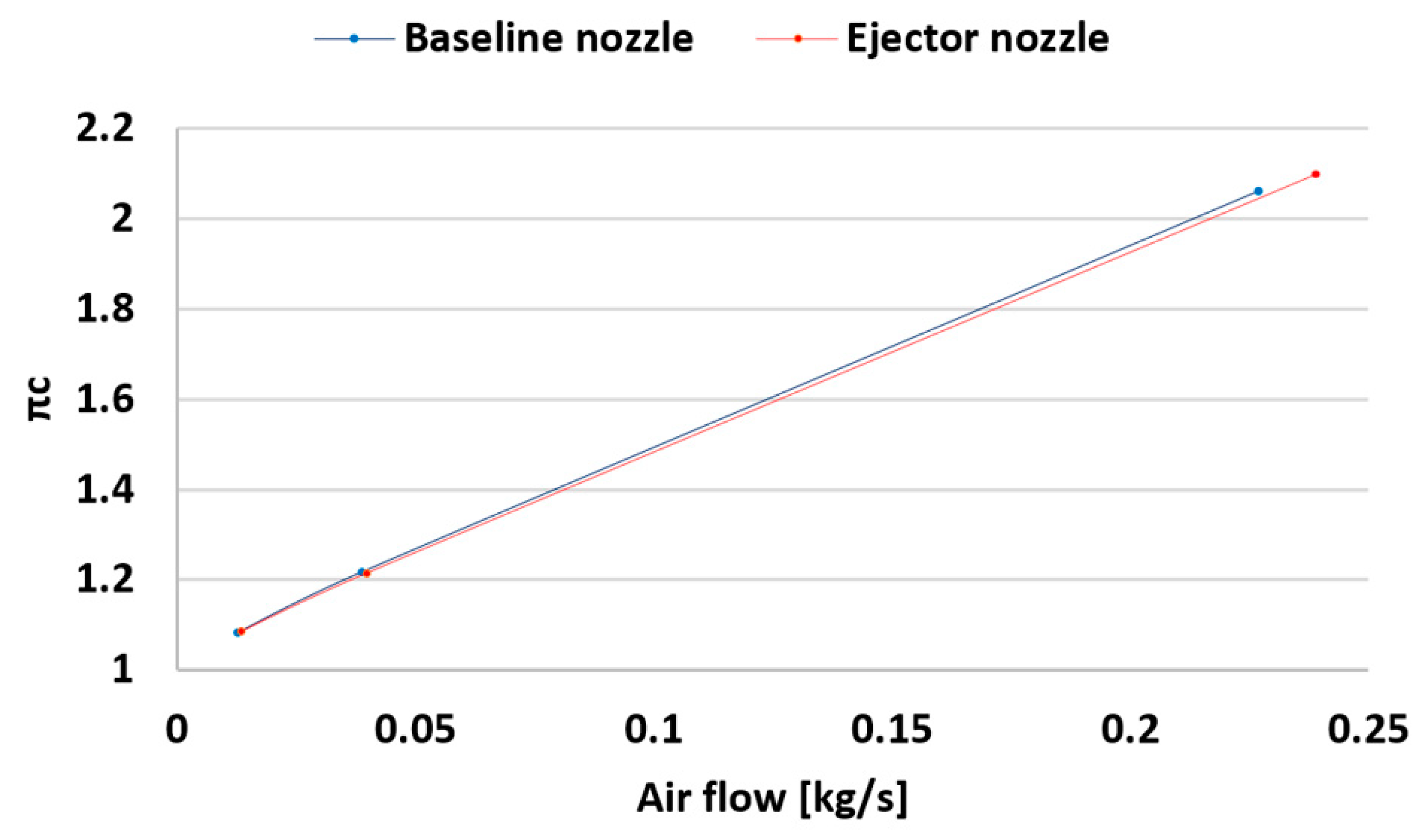
3.1. Engine Performance

The experimental engine performances were in both stable operational states of the engine and transient performances.

3.1.1. Stable Operational States of the Engine Performance

The jet ejector’s performance was assessed using the measured parameters as in Table 2. The temperature at intake level T1 was regarded as being the temperature value in front of the micro turbojet engine. These variables were used to determine the specific consumption and engine efficiency, and the mathematical relation (Equation (1)—specific consumption S; Equation (2)—compressor efficiency ηc) between them is expressed as [37]
S = 3600 F f F   [ kg N h ]
η c = c p T 1 ( π c k 1 k 1 ) c p T 2 c p T 1
where k is the adiabatic exponent and cp the specific heat capacity. The resulted engine characteristics, shown in Table 1, were utilized to calculate the compressor efficiency and specific consumption.
The ambient temperature value used for the measurements, taken close to the intake engine, was T1 = 291 K.
The force thrust, specific fuel consumption and compressor efficiency compared to the baseline nozzle and their variation over the tested regimes are shown below in the graphs (Figure 17, Figure 18 and Figure 19) for a clearer understanding of the engine characteristics shown in Table 1.
The characteristics visualized on the graphs show that, when the ejector is employed in regimes 2 and 3, the temperature in front of the turbine decreases as well as increases in the idle regime, and the engine’s compression ratio exhibits no significant fluctuations in any operating regime. When the ejector nozzle is utilized, the fuel flow decreases during all test regimes. One of the most significant findings is that the produced force increases when the ejector nozzle is utilized with a larger number of chevrons, and the intake air flow follows a similar downward pattern. Comparing the current ejector nozzle case to the reference one, the specific fuel consumption decreases.

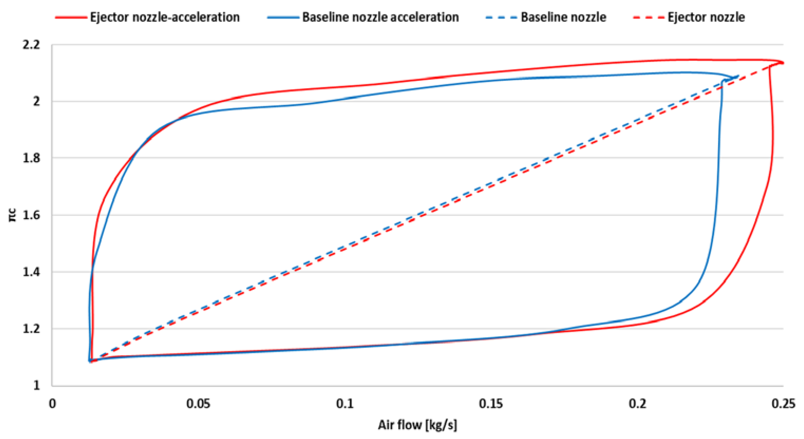
3.1.2. Transient Performance

In order to analyze the stability of the ejector micromotor, tests were also carried out at transient states, accelerations and decelerations. The first step was to draw the working line of the micromotor (Figure 20).
Figure 20 reveals that, while the surge line was not crossed, the operating lines of the compressor for the ejector nozzle were somewhat adjusted without affecting the engine’s structural integrity.
Next, the variation of the operating line for a sudden acceleration and deceleration is presented (Figure 21).
From Figure 21, it can be seen that, during a sudden acceleration, the operation of the engine in the case of being equipped with an ejector comes closer to the pumping limit. During a sudden deceleration, it can be observed that, in the case of using the ejector, the jet cycle moves closer to a blocking limit. During both operations, sudden acceleration and sudden deceleration, the unity and operationality of the engine were not put at risk.
Figure 22 shows the temperature variation in front of turbine T3 during sudden acceleration and deceleration with and without the ejector.
From the above graph, it can be seen that the temperature in front of the turbine is lower during sudden acceleration, idling and sudden deceleration without endangering the integrity and functionality of the engine. This is true even after the engine has been in the regime for a few seconds to stabilize before being suddenly decelerated.

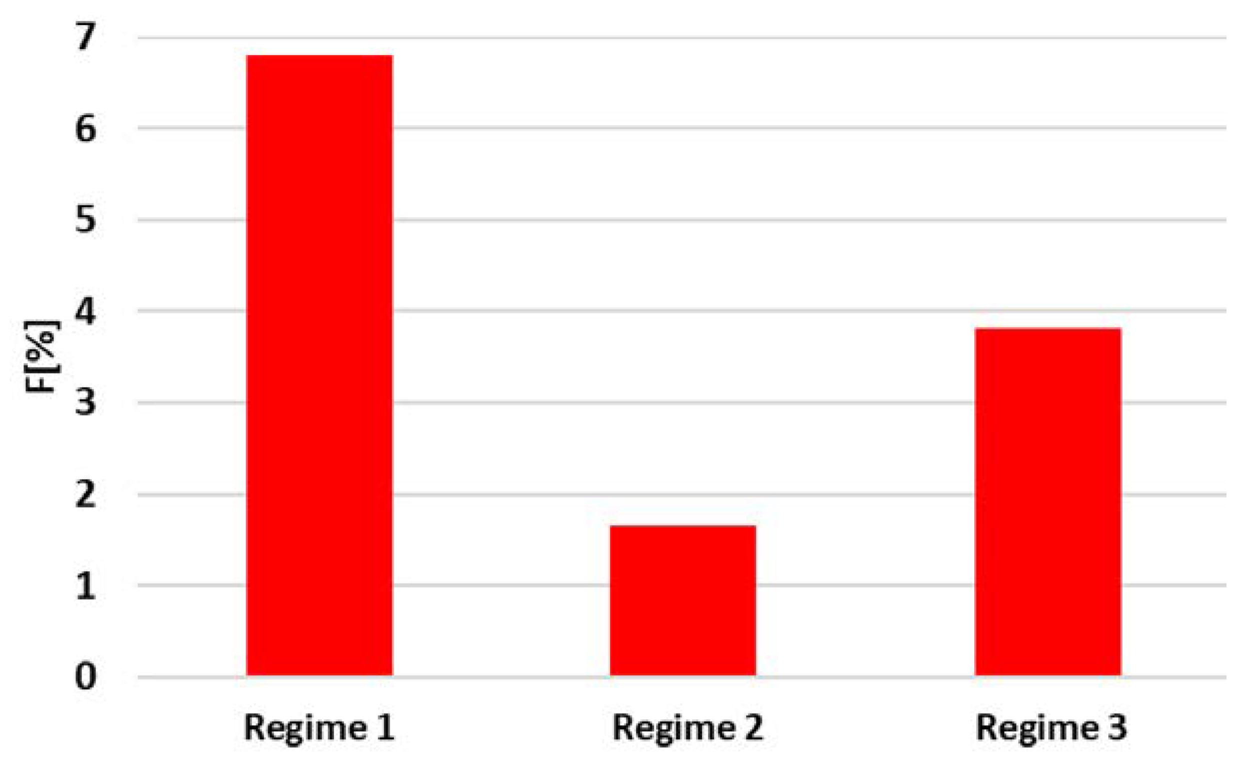
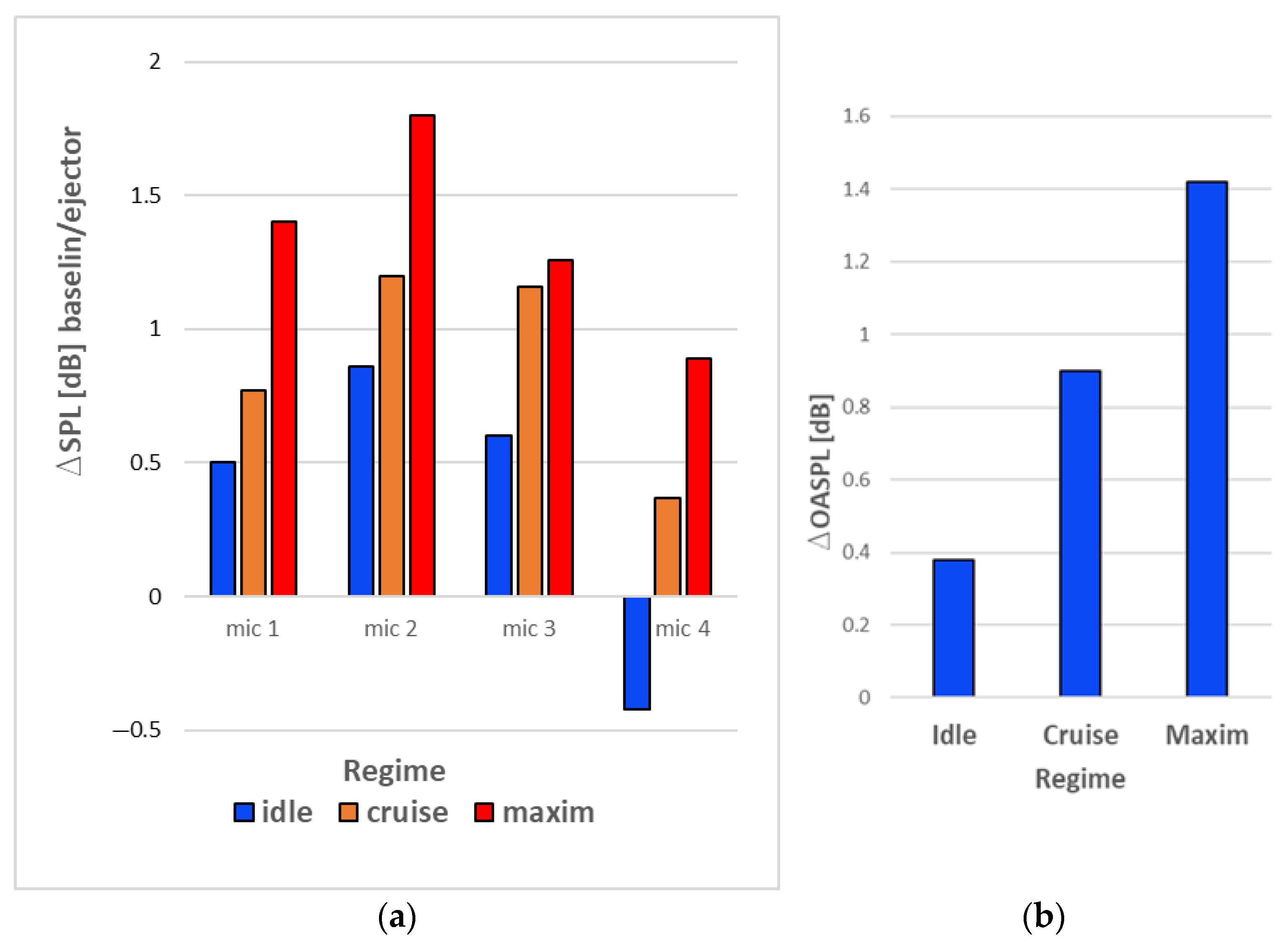
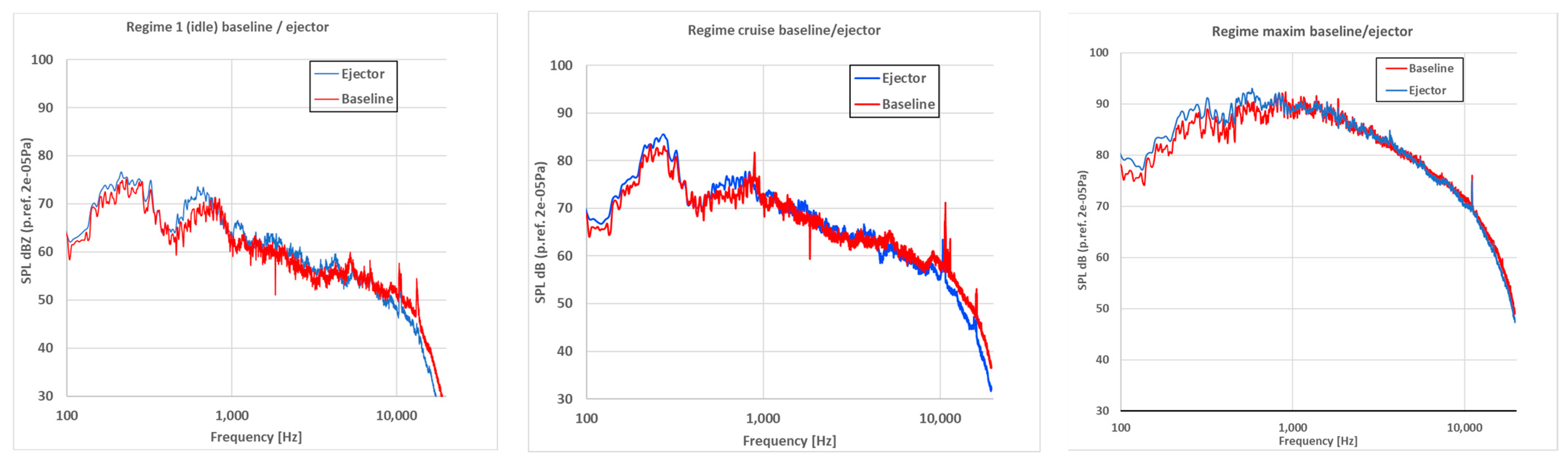
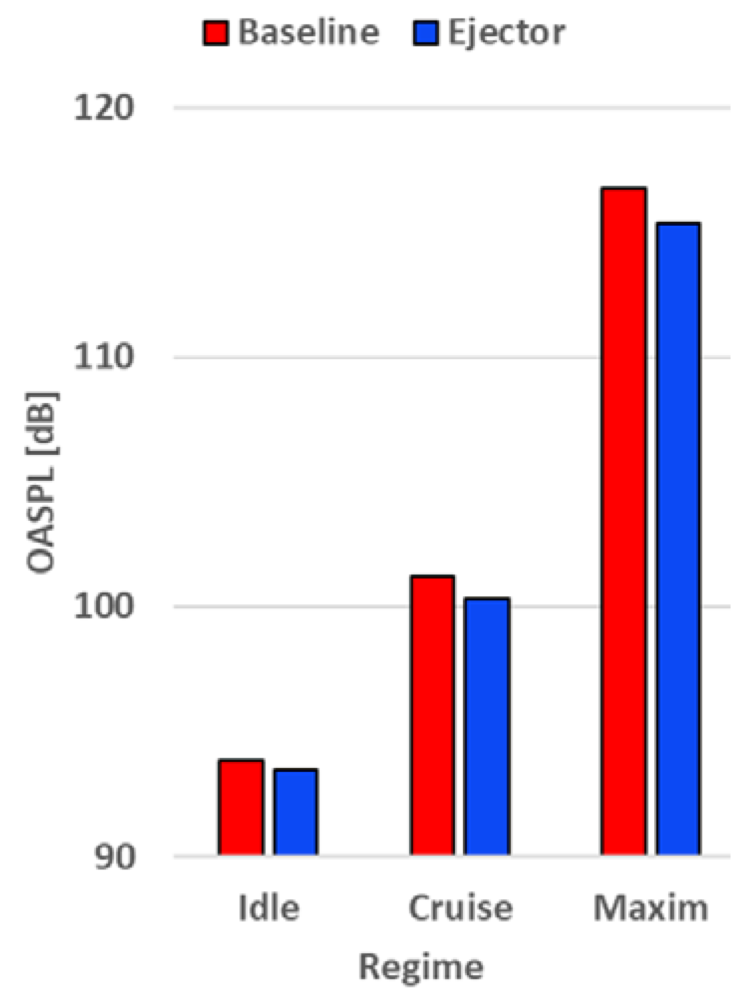
3.2. Acoustic Evaluation Results

The noise reduction in the hot jet gases passing through an ejector nozzle as compared to the reference nozzle was studied in the present article, and it must be noted that, in addition to the jet noise, there are numerous other sound sources produced by the micro engine while it is operating, including air flow at the input zone, turbulences produced by the air flow at the compressor, mechanical noise produced by the rotation of the shaft, rotor-stator reciprocation Blade Passing Frequency (BPF), combustion noise, etc.
The jet noise, which is created while turbulently mixing high-speed gases with the surrounding air, is the parameter of interest that is analyzed in this study. It is required to recognize the frequency spectrum components of the noise sources, which were earlier discussed, with the filtering of the components that are not of importance to us; as a result, we can compare the reduction in noise, created simply by the jet gases, by the ejector nozzle. The engine parameters and acoustic signal data were recorded and analyzed, and their centralization is shown in the next section. The Fast Fourier Transform (FFT) function in the frequency domain and averaging the total time length were used to analyze the acoustic raw data. The noise spectra from the four microphones were averaged using Equation (3) for better comparability and graphical representation, and a spectrum was produced for each tested configuration and regime.
L p = 10 lg 1 n i = 1 n 10 L i / 10
where Lp represents the average sound pressure level, n is the number of microphones and Li is the individual sound pressure levels in decibels for each microphone. Applying a band-stop filter to the spectrum components of shaft speed, compressor, turbine BPF and its harmonics served as the first stage of noise-signal filtering.
In Figure 23, the filtered averaged sound spectra for each regime and nozzle configuration are presented.
The tonal components that correspond to engine speed have greater amplitudes in the unfiltered noise spectra, especially at high engine speeds corresponding to the maximum regime, and when the band-stop filter is applied, a broad acoustic spectrum results. When all the spectra from all regimes are compared, a broadband component with a peak at approximately 200 Hz is found; this component’s maximum peak frequency is not considerably affected by the engine speed. This component is thought to be created by combustion; hence, it will not be considered when calculating the total sound pressure level.
Table 2 displays the overall sound pressure levels (OASPL) for each microphone, each regime and each nozzle. Based on the filtered sound spectra shown in Figure 23 with a frequency range of 100–20,000 Hz, the acoustic OASPL were calculated.
The averaged OASPL for each regime and nozzle configuration were determined based on the overall sound pressure levels in each microphone shown in Table 2; the findings are shown in Figure 24.
The noise reduction in the ejector nozzle was calculated using these OASPL shown in Figure 24, using the baseline nozzle noise as a reference. Figure 25 shows the noise reductions for the nozzle in each regime.
The nozzle ejector utilization resulted in a minor reduction in noise for the first regime; however, at higher regimes with high gas velocities, the ejector started to take action, and the noise was decreased by an average of 1 dB and as much as 1.7 dB on microphone location 2 in Regime 3 (maximum).
From a functional point of view, the ejector effect was steady for all three regimes; nevertheless, at the location of microphone 4, where the idle regime was seen, an increase in noise of 0.4 dB was noted. The bigger surface area of the reference nozzle acts as an obstruction; thus, it is assumed that, by shortening or shrinking the nozzle with the ejector, the noise from inside the engine is propagating more readily. The alteration of the engine operating line is one theory for the noise increase.

4. Conclusions

The main conclusions of this study are that, by using an ejector designed and optimized for the Jet Cat P80 micromotor, its performance in terms of power and consumption are improved, and the acoustic pressure level is decreased.
By testing the micromotor on three representative regimes (Regime 1—idle, Regime 2—cruise and Regime 3—almost max), it was observed that the engine performances, in terms of engine traction force, increased up to 7 percent for regime 1, 2 percent for regime 2 and approximately 4 percent for regime 3, and in terms of specific consumption, the engine specific consumption decreased up to 12 percent for regime 1 and approximately 5% for regimes 2 and 3.
By testing the micromotor with and without an ejector at transient regimes of sudden acceleration and deceleration, the stability of the motor was not put at risk.
The concluding remark is that the noise mitigation of more than 1 dB comes with an increase in the engine performance, and the stability and the integrity of the engine were not in danger.
The ejector nozzle could be a solution to reduce the fuel consumption and acoustic pressure level of micro turbojet engines, and also, this solution could be extended to other turbo engine types.
Future work will be focused on ejector nozzles developed in combination with special mixer nozzles or a combination with chevrons having the goal of increasing the pumping performance, thrust augmentation and jet noise reduction.

Author Contributions

G.C. and D.-E.C.; Conceptualization, T.-F.F.; Nozzle ejector manufacturing, L.C. and G.C.; Acoustic evaluation, G.C. and D.-E.C.; Micro turbojet engine performance evaluation. All authors have read and agreed to the published version of the manuscript.

Funding

This research was carried out under “Nucleu” Program, Grant no. 12N/2023, Project PN 23.12.03.01, funded by Romanian Ministry of Research, Innovation and Digitization. The APC was also funded by Romanian Ministry of Research, Innovation and Digitization through “Nucleu” Program, Grant no. 31N/2023.

Institutional Review Board Statement

Not applicable.

Informed Consent Statement

Not applicable.

Data Availability Statement

Not applicable.

Conflicts of Interest

The authors declare no conflict of interest.

References

  1. Guercio, V.; Pojum, I.C.; Leonardi, G.S.; Shrubsole, C.; Mac Gowers, A.; Dimitroulopoulou, S.; Exley, K.S. Exposure to indoor and outdoor air pollution from solid fuel combustion and respiratory outcomes in children in developed coun-tries: A systematic review and meta-analysis. Sci. Total. Environ. 2021, 755, 142187. [Google Scholar] [CrossRef] [PubMed]
  2. European Union Aviation Safety Agency. European Aviation Environmental Report; European Union Aviation Safety Agency: Köln, Germany, 2019.
  3. Bogdanov, D.; Gulagi, A.; Fasihi, M.; Breyer, C. Full energy sector transition towards 100% renewable energy supply: Integrating power, heat, transport and industry sectors including desalination. Appl. Energy 2021, 283, 116273. [Google Scholar] [CrossRef]
  4. Gössling, S.; Humpe, A. The global scale, distribution and growth of aviation: Implications for climate change. Glob. Environ. Chang. 2020, 65, 102194. [Google Scholar] [CrossRef]
  5. Zhao, K.; Okolo, P.; Neri, E.; Chen, P.; Kennedy, J.; Bennett, G. Noise reduction technologies for aircraft landing gear—A bibliographic review. Prog. Aerosp. Sci. 2020, 112, 100589. [Google Scholar] [CrossRef]
  6. Torija, A.; Self, R. Aircraft classification for efficient modelling of environmental noise impact of aviation. J. Air Transp. Manag. 2018, 67, 157–168. [Google Scholar] [CrossRef]
  7. Cican, G.; Deaconu, M.; Mirea, R.; Ceatra, L.C.; Cretu, M. An Experimental Investigation to Use the Biodiesel Resulting from Recycled Sunflower Oil, and Sunflower Oil with Palm Oil as Fuels for Aviation Turbo-Engines. Int. J. Environ. Res. Public Health 2021, 18, 5189. [Google Scholar] [CrossRef]
  8. Zhang, H.; Fang, Y.; Wang, M.; Appels, L.; Deng, Y. Prospects and perspectives foster enhanced research on bio-aviation fuels. J. Environ. Manag. 2020, 274, 111214. [Google Scholar] [CrossRef]
  9. Cican, G.; Toma, A.; Puşcaşu, C.; Catana, R. Jet CAT P80 thermal analyses and performance assessment using different fuels types. J. Therm. Sci. 2018, 27, 389–393. [Google Scholar] [CrossRef]
  10. Hoelzen, J.; Silberhorn, D.; Zill, T.; Bensmann, B.; Hanke-Rauschenbach, R. Hydrogen-powered aviation and its reliance on green hydrogen infrastructure—Review and research gaps. Int. J. Hydrog. Energy 2022, 47, 3108–3130. [Google Scholar] [CrossRef]
  11. Petrescu, R.V.; Machín, A.; Fontánez, K.; Arango, J.; Márquez, F.; Petrescu, F.I. Hydrogen for aircraft power and propulsion. Int. J. Hydrog. Energy 2020, 45, 20740–20764. [Google Scholar] [CrossRef]
  12. Pelz, P.; Leise, P.; Meck, M. Sustainable aircraft design—A review on optimization methods for electric propulsion with derived optimal number of propulsors. Prog. Aerosp. Sci. 2021, 123, 100714. [Google Scholar] [CrossRef]
  13. Dahal, K.; Brynolf, S.; Xisto, C.; Hansson, J.; Grahn, M.; Grönstedt, T.; Lehtveer, M. Techno-economic review of alternative fuels and propulsion systems for the aviation sector. Renew. Sustain. Energy Rev. 2021, 151, 111564. [Google Scholar] [CrossRef]
  14. Cican, G. Marius Deaconu and Daniel-Eugeniu Crunteanu, Impact of Using Chevrons Nozzle on the Acoustics and Performances of a Micro Turbojet Engine. Appl. Sci. 2021, 11, 5158. [Google Scholar] [CrossRef]
  15. Crispo, C.M.; Greco, C.S.; Cardone, G. Flow field features of chevron impinging synthetic jets at short nozzle-to-plate distance. Exp. Therm. Fluid Sci. 2019, 106, 202–214. [Google Scholar] [CrossRef]
  16. Ferrante, P.; De Roeck, W.; Desmet, W.; Magnino, N. Back-to-back comparison of impedance measurement techniques applied to the characterization of aero-engine nacelle acoustic liners. Appl. Acoust. 2016, 105, 129–142. [Google Scholar] [CrossRef]
  17. Sadeghian, M.; Bandpy, M.G. Technologies for aircraft noise reduction: A review. J. Aeronaut. Aerosp. Eng. 2020, 9, 219. [Google Scholar]
  18. Liu, X.; Zhao, D.; Guan, D.; Becker, S.; Sun, D.; Sun, X. Development and progress in aeroacoustic noise reduction on turbofan aeroengines. Prog. Aerosp. Sci. 2022, 130, 100796. [Google Scholar] [CrossRef]
  19. Kracik, J.; Dvorak, V. Secondary flow choking in axisymmetric supersonic air ejector with adjustable mo-tive nozzle. Appl. Therm. Eng. 2022, 204, 117936. [Google Scholar] [CrossRef]
  20. Keenan, J.H.; Neumann, E.P.; Lustwerk, F. An Investigation of Ejector Design by Analysis and Experiment. J. Appl. Mech. 1950, 17, 299–309. [Google Scholar] [CrossRef]
  21. Zhang, Z.; Wang, C.; Yang, S.; Cheng, F.; Geng, J.; Yang, Z.; Lyu, Y.; Yu, L. Research on performance of multi-nozzle ejector for aeroengine air system. Therm. Sci. Eng. Prog. 2023, 38, 101651. [Google Scholar] [CrossRef]
  22. Zhang, Z.; Feng, X.; Tian, D.; Yang, J.; Chang, L. Progress in ejector-expansion vapor com-pression refrigeration and heat pump systems. Energy Convers. Manag. 2020, 207, 112529. [Google Scholar] [CrossRef]
  23. Available online: https://aviation.stackexchange.com/questions/37332/what-is-this-ring-shaped-device-behind-this-dc-8s-jet-engine (accessed on 10 July 2021).
  24. Jack, C.; Ned, A. The Engines of Pratt & Whitney: A Technical History; American Institute of Aeronautics and Astronautics: Reston, VA, USA, 1020; pp. 321–333. ISBN 9781-60086-711-8. [Google Scholar]
  25. Peng, C.; Fan, W.; Zhang, Q.; Yuan, C.; Chen, W.; Yan, C. Experimental study of an air-breathing pulse detonation engine ejector. Exp. Therm. Fluid Sci. 2011, 35, 971–977. [Google Scholar]
  26. Shi, L.; Zhao, G.; Yang, Y.; Qin, F.; Wei, X.; He, G. Experimental study on ejector-to-ramjet mode transition in a divergent kerosene-fueled RBCC combustor with low total temperature inflow. Aerosp. Sci. Technol. 2020, 99, 105734. [Google Scholar] [CrossRef]
  27. Shi, L.; Zhao, G.; Yang, Y.; Gao, D.; Qin, F.; Wei, X.; He, G. Research progress on ejec-tor mode of rocket-based combined-cycle engines. Prog. Aerosp. Sci. 2019, 107, 30–62. [Google Scholar] [CrossRef]
  28. Chen, H.; Zhang, H.; Xi, Z.; Zheng, Q. Modeling of the turbofan with an ejector nozzle based on infrared prediction. Appl. Therm. Eng. 2019, 159, 113910. [Google Scholar] [CrossRef]
  29. Khalid, S.; Sokhey, J.; Chakka, P.; Pierluissi, A. Ejector/Engine/Nacelle Integration for Increased Thrust minus Drag. In Proceedings of the 46th AIAA/ASME/SAE/ASEE Joint Propulsion Conference & Exhibit, Nashville, TN, USA, 25–28 July 2010. [Google Scholar]
  30. Schmidt, R.; Hupfer, A. Design and numerical simulation of ejector nozzles for very small turbojet engines. CEAS Aeronaut. J. 2021, 12, 923–940. [Google Scholar] [CrossRef]
  31. Tashtoush, B.M.; Al-Nimr, M.A.; Khasawneh, M.A. A comprehensive review of ejector design, performance, and applications. Appl. Energy 2019, 240, 138–172. [Google Scholar] [CrossRef]
  32. Jet Cat USA. Jet Cat Instruction Manual. U.S. Patent 6216440, 17 April 2001.
  33. Constantinescu, V.; Galetuse, S. Mecanica Fluidelor si Elemente de Aerodinamica; Editura Didactica si Pedagogica: Bucuresti, Romania, 1983. [Google Scholar]
  34. Dong, Z.; Sun, M.; Wang, Z.; Cai, Z.; Yao, Y.; Gu, R. Numerical investigation on flow and mixing characteristics inside a converging-diverging mixing duct of rocket-based combined-cycle engine in ejector mode. Aerosp. Sci. Technol. 2020, 106, 106102. [Google Scholar] [CrossRef]
  35. Zhang, K.; Zhu, X.; Ren, X.; Qiu, Q.; Shen, S. Numerical investigation on the effect of nozzle position for design of high performance ejector. Appl. Therm. Eng. 2017, 126, 594–601. [Google Scholar] [CrossRef]
  36. Ye, W.; Zhang, J.; Xu, W.; Zhang, Z. Numerical investigation on the flow structures of the multistrut mixing enhancement ejector. Appl. Therm. Eng. 2020, 179, 115653. [Google Scholar] [CrossRef]
  37. Mattingly, J. Elements of Propulsion: Gas Turbines and Rockets, 2nd ed.; American Institute of Aeronautics and 557 Astronautics: Reston, VA, USA, 2006. [Google Scholar]
Figure 1. Test bench and instrumentation: (a) engine without the ejector nozzle, (b) engine with the ejector nozzle.
Aerospace 10 00162 g001
Figure 2. Principal scheme of an ejector, where 1 is the nozzle inlet, 2 is the nozzle exit, 3 is the ejector exit, 4 is the ejector inlet and 5 is the section between the nozzle exit and the ejector.
Aerospace 10 00162 g002
Figure 3. Scheme of the ejector for the Jet Cat P80 micromotor (a) and the nozzle of the micromotor (b).
Aerospace 10 00162 g003
Figure 4. The mesh for the entire flow domain without ejector (a) and detail (b).
Aerospace 10 00162 g004
Figure 5. The mesh for the entire flow domain with ejector (a) and detail (b).
Aerospace 10 00162 g005
Figure 6. Velocity field and streamlines for the base case without the ejector.
Aerospace 10 00162 g006
Figure 7. Velocity field and streamlines for the case when section 5 has a value of 1 mm.
Aerospace 10 00162 g007
Figure 8. Velocity field and streamlines for the case when section 5 has a value of 3 mm.
Aerospace 10 00162 g008
Figure 9. Velocity field and streamlines for the case when section 5 has a value of 5 mm.
Aerospace 10 00162 g009
Figure 10. Velocity field and streamlines for the case when section 5 has a value of 8 mm.
Aerospace 10 00162 g010
Figure 11. Velocity field and streamlines for the case when section 5 has a value of 11 mm.
Aerospace 10 00162 g011
Figure 12. Velocity field and streamlines for the case when section 5 has a value of 12 mm.
Aerospace 10 00162 g012
Figure 13. The variation of the propulsion force read in section 3 obtained through numerical simulations for the variation of section 5.
Aerospace 10 00162 g013
Figure 14. The variation of the gas flow rate read in section 3 obtained through numerical simulations for the variation of section 5.
Aerospace 10 00162 g014
Figure 15. The variation of the exhaust velocity of the gases read in section 3 obtained in the numerical simulations for the variation of section 5.
Aerospace 10 00162 g015
Figure 16. The dimensions of the nozzle ejector.
Aerospace 10 00162 g016
Figure 17. Variation of the engine thrust depending on the regime.
Aerospace 10 00162 g017
Figure 18. Variation of the specific fuel consumption depending on the regime.
Aerospace 10 00162 g018
Figure 19. Variation of the compressor efficiency depending on the regime and nozzle type.
Aerospace 10 00162 g019
Figure 20. Engine operating line.
Aerospace 10 00162 g020
Figure 21. Variation of the operating line of the engine during sudden acceleration and deceleration.
Aerospace 10 00162 g021
Figure 22. Temperature variation in front of the turbine during acceleration and sudden acceleration.
Aerospace 10 00162 g022
Figure 23. Averaged noise spectra for each configuration and regime.
Aerospace 10 00162 g023
Figure 24. Averaged OASPL variation depending on the tested regime and nozzle configuration.
Aerospace 10 00162 g024
Figure 25. Noise reduction in the ejector nozzle for all the tested regimes by microphone location (a) and averaged (b).
Aerospace 10 00162 g025
Table 1. Turbojet engine operating parameters.
Regime
Speed n (rpm)
Nozzle TypeT2
[K]
T3
[K]
πcQc
[L/h]
F
[N]
S
[Kg/Nh]
ηc
[%]
1Idle
35,000
baseline23.4637.01.0836.884.541.2130.72
ejector22.0663.11.0856.594.871.0830.86
2Cruise
55,000
baseline34.1606.01.21610.1913.320.6120.83
ejector32.4587.21.2159.8913.540.5840.90
3Maxim
110,000
baseline102.0655.22.05922.0072.930.2410.76
ejector88.2600.62.09821.8275.830.2300.93
Table 2. Acoustic results.
Regime/Speed n (rpm)Nozzle TypeMic 1 (dB)Mic 2 (dB)Mic 3 (dB)Mic 4 (dB)
1Idle
35,000
baseline93.4694.0094.3393.49
ejector92.9693.1493.7393.91
2Cruise
55,000
baseline101.33101.54101.50100.47
ejector100.56100.34100.34100.10
3Maxim
110,000
baseline118.16117.72115.89114.19
ejector116.76115.92114.63113.30
Disclaimer/Publisher’s Note: The statements, opinions and data contained in all publications are solely those of the individual author(s) and contributor(s) and not of MDPI and/or the editor(s). MDPI and/or the editor(s) disclaim responsibility for any injury to people or property resulting from any ideas, methods, instructions or products referred to in the content.

