Article

An Efficient Approach for Parametric Modeling and Prediction of the Hollow Blade Manufacture Shape

1
Research Institute of Aero-Engine, Beihang University, Beijing 100191, China
2
School of Energy and Power Engineering, Beihang University, Beijing 100191, China
3
Beijing Key Laboratory of Aero-Engine Structure and Strength, Beijing 100191, China
4
United Research Center of Mid-Small Aero-Engine, Beijing 100191, China
*
Author to whom correspondence should be addressed.
Aerospace 2023, 10(2), 145; https://doi.org/10.3390/aerospace10020145
Submission received: 1 January 2023 / Revised: 28 January 2023 / Accepted: 2 February 2023 / Published: 5 February 2023

Abstract

:
In recent years, hollow fan blades have been widely used to meet the requirements of aeroengines for lightweight and better performance. However, the hollow fan blade will change from the manufacture shape to the operating shape with large deformations during operation. This deviation, if neglected, will lead to deceptive results for structural and aerodynamic analysis. However, the existing methods have low prediction accuracy or require a lot of calculation in case of large deformations. In this paper, an iterative method for parametric modeling, automatic generation of finite element model, and hot-to-cold analysis of an H-shaped hollow fan blade are proposed. The accuracy and efficiency of the traditional uncoupling (UCM) and weak coupling methods (WCS), as well as the proposed strong–weak coupling method (SWCS), are compared with the strong coupling method (SCU) as a reference. Results show that improvements in the prediction accuracy can be made by the SWCS method, and the error of the maximum blade deformation is 2.3%, while the error of the UCM method and WCS method is 30% and 12%, respectively. An excellent agreement can be observed between the SWCS and SCU methods in the whole blade height with errors of 2%~5%, and the calculation time of the SWCS method is only 2.5% of the SCU method, which is reduced from 7200 min to 180 min, making it possible to conduct the hot-to-cold analysis at the design stage.

1. Introduction

Modern aeroengines pursue higher thrust-to-weight ratios, better aerodynamic performance, and stronger structural strength, which impose new requirements on materials, aerodynamic layout, structural design, and manufacturing processes. Compared with the conventional solid fan blades, wide-chord hollow fan blades have outstanding advantages in increasing engine surge margin, resisting foreign object damage and reducing structural weight [1], and have become a widely used structural design for advanced turbofan engines. However, the complex internal structure of hollow fan blades brings great challenges to manufacturing feasibility, structural integrity, and maintenance capability [2].
The early exploration of hollow fan blades mainly focused on the research of manufacturing processes. The superplastic forming, combined with the diffusion bonding (SPF/DB) process, has been extensively evaluated from diamond-shaped specimens to full-size prototype blades [3] and has become the main manufacturing process of hollow fan blades due to the weight and cost advantages [4,5]. Since the 1980s, Rolls-Royce and Pratt & Whitney Aircraft have explored hollow fan blades with different configurations of reinforcing ribs. Based on the SPF/DB process, hollow fan blades with honeycomb structure, triangular truss structure, and H-shaped structure have been successively designed, as shown in Figure 1 [6]. Compared with the honeycomb structure, triangular truss and H-shaped structures have better weight reduction and strength performance and have been widely applied to advanced turbofan engines. In the early 21st century, researchers have been committed to designing novel hollow fan blades, including composite material filling [7], low-noise consideration [8], airflow passage design [9], and topology optimization of rib structure [10,11,12]. However, the triangular truss and H-shaped structures are still the most widely used hollow fan blades due to their mature design and manufacturing level.
Regarding the analysis of hollow fan blades, researches mainly focused on the influence of structural parameters on blade strength [13], stiffness [14], damping characteristics [6,15], optimization of rib structure [16,17], and numerical simulation of the bird strike [18,19]. However, the above researches are based on the operating blade shape (deformed hot blade). However, the strength analysis should be carried out for the manufacture blade shape (cold blade before deformation). This deformation caused by centrifugal loads, aerodynamic pressures, and non-uniform temperature distribution is an important result for strength analysis and structural design. Results show that differences in blade shape significantly affect the aerodynamic loads, aeroelastic response and noise levels [20,21]. Since hollow fan blades have lower stiffness, the deformation will be more considerable than normal and cannot be ignored.
To ensure the strength analysis and structural design of the hollow fan blade, the accurate prediction of the manufacture blade shape from the known aerodynamic design shape (called a hot-to-cold analysis) is crucial. Fu [22] proposed an uncoupling method for the hot-to-cold analysis applied to the solid fan blade. Zhang [6] proposed a weak coupling method and assumed that aerodynamic loads were constant during hot-to-cold analysis. However, due to the large deformation of hollow blades, the above constant flow assumption and uncoupling treatments are no longer effective. Yang [23] calculated the unsteady aerodynamic loads of each estimated blade shape in detail, which requires a huge amount of calculation and is difficult to meet the needs of design applications. Therefore, a fast and properly coupled method is needed in the hot-to-cold analysis. Besides, the initial hot blade shape is a solid blade. To ensure the automatic hot-to-cold analysis of the hollow fan blade, it is necessary to realize the automatic FEM generation of hollow fan blades based on the structural parameters.
In this paper, an automatic iteration method from the solid aerodynamic design blade to the hollow manufacture blade is established for the typical H-shaped hollow fan blade. It is arranged as follows: the methods for the determination of hollow manufacture blade are proposed in Section 2, including the model parameterization method; the auto-generation method of FEM; and the hot-to-cold analysis methods. A description of the test rig is presented in Section 3. Performances of four hot-to-cold methods are compared in Section 4. Then the paper ends with concluding remarks.

2. Numerical Methodology

2.1. Model Parameterization of Hollow Fan Blade

The hollow fan blade can be divided into outer-profile and inner-hollow parts. The design of the outer-profile is based on aerodynamic performance, which is similar to the solid blade. The design of the inner-hollow needs to consider weight reduction, manufacturing technology and strength requirements. For H-shaped hollow fan blades, the main structural features include the upper, lower, leading, and trailing boundaries of the cavity, the inner and outer panels, fillets, and ribs. To reasonably parameterize the hollow fan blade, eight structural parameters are proposed, as shown in Table 1. Figure 2 shows the hollow section with 3 and 4 uniformly distributed ribs, where N1 and N2 are the distances from the leading and trailing edges to the boundaries of the cavity, which are related to the wall thickness and outermost-fillet radius.
In order to describe the structural features simply and comprehensively, the following principles are proposed.
(1) In the hollow section, the wall thickness, rib thickness, and position are symmetrically distributed.
(2) The thicknesses and positions of ribs on the same side of the symmetry axis are independent.
(3) The leading and trailing boundaries of the cavity are determined by the outermost-fillet radius and the wall thickness. The position where the fillet radius can be accommodated is defined as the boundary of the cavity.
(4) The wall is divided into equal-thickness and variable-thickness regions along the chordline. The equal-thickness region is near the leading and trailing boundaries of the cavity, and the rest is the variable-thickness region.
(5) Five uniformly distributed hollow sections are chosen to describe the wall thickness variation along the blade height. Other sections are interpolated by cubic splines according to these five sections.

2.2. Auto-Generation Method of FEM

Before the establishment of the FEM, it is necessary to determine the positions of the cavity, ribs, and fillets based on structural parameters, as shown in Figure 3. The key points are as follows.
(1) Outer-wall surface is fitted by data points of the blade’s outer-profile using bicubic spline interpolation.
(2) Inner-wall surface is obtained by offsetting the outer-wall curve inward by wall thickness in the normal direction.
(3) Upper and lower boundaries of the cavity are determined by parameters M1 and M2.
(4) New curves can be obtained by offsetting the inner-wall curves inward by the fillet radius, and the intersection of the new curves is the center of the outermost-fillet. The tangent of the fillet is the leading and trailing boundary of this hollow section. The maximum value of N1 in all hollow sections is considered the cavity boundary, and the same goes for N2.
(5) The centerline of ribs can be obtained according to the parameter H when the cavity boundaries are determined. Curves on both sides can be obtained by rib thickness.
(6) The inner-fillet radius can be calculated by Equation (1). Then, the position of the tangent point on the inner-wall curve can be adjusted until the fillet radius is satisfied.
R = l sin θ tan ( θ 2 )
where θ is the angle between the rib and the tangent direction of the point on the inner-wall curve, and l is the distance from this point to the rib.
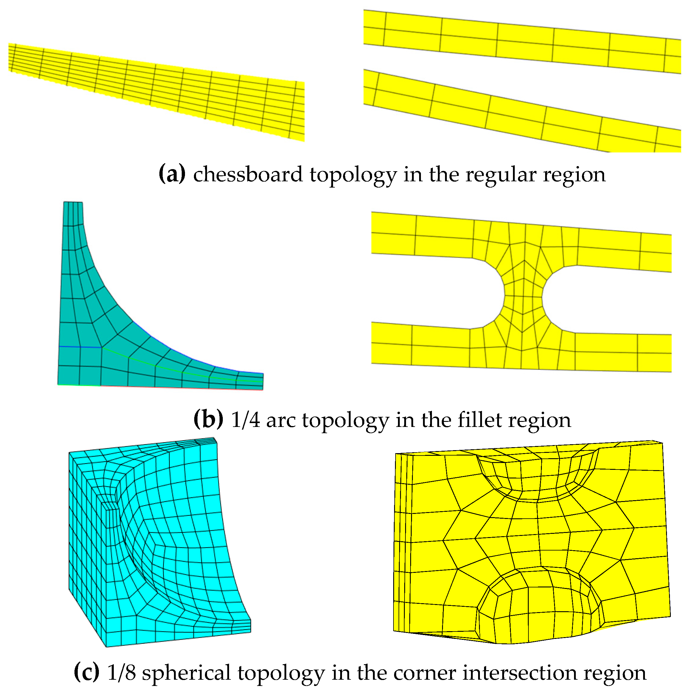
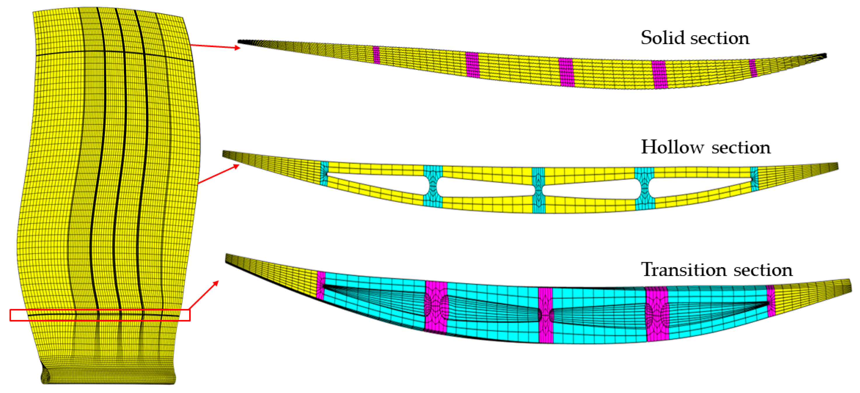
Then the FEM can be established using MATLAB software. According to the structural features, the hollow fan blade can be divided into solid, transition, and hollow sections, as shown in Figure 4. The solid and hollow sections have their own FEM topologies. The transition section is divided into several regions along the chordline with different mesh topologies, such as regular regions with the chessboard topology, fillet regions with the 1/4 arc topology, and corner intersection regions with the 1/8 spherical topology, as shown in Figure 5. The quadrilateral meshes of each section are created by corresponding nodes on the feature curves first. Then the hexahedral elements are composed of the quadrilateral meshes of adjacent sections.

2.3. Hot-to-Cold Analysis Methods

The hot-to-cold analysis is a multidisciplinary iterative process of fluid, structural and thermal fields. The pressure and temperature distributions on the blade surface are obtained by solving the three-dimensional compressible Reynolds-averaged Navier-Stokes equations with the k-ε turbulence model in double precision. The high-resolution scheme is used to calculate the advection term and turbulence numerics. The structural analysis is performed under the force and displacement constraints. Nonlinear effects such as large deformation, stress stiffening and rotational softening are considered in the calculation. Four hot-to-cold analysis methods, with different coupling levels, are given below.

2.3.1. Uncoupling Method without Flow Simulation (UCM)

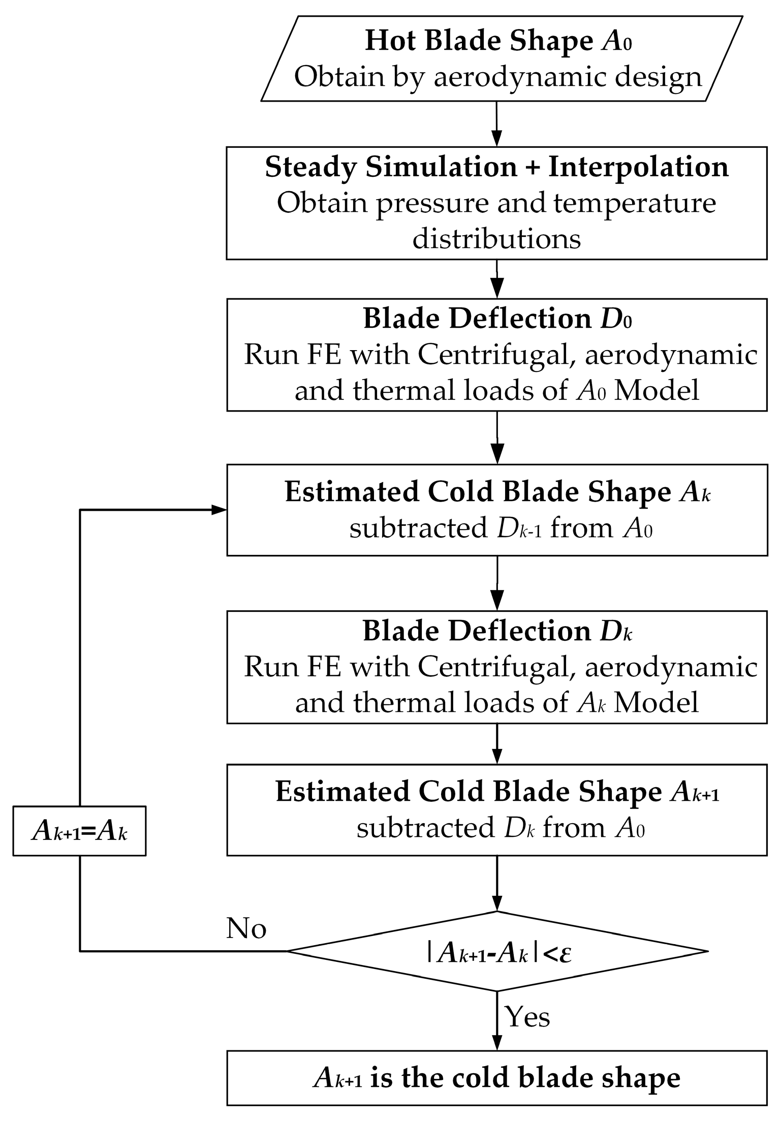
For the UCM method, only centrifugal loads are considered in the hot-to-cold analysis [22]. For a given hot blade, the blade deflections caused by centrifugal loads are calculated by the structural solver. An estimate of the cold blade shape is then determined by subtracting the blade deflections from the hot blade. This process is repeated until a convergent cold blade shape is obtained, as shown in Figure 6.

2.3.2. Weak Coupling Method with Steady Simulation (WCS)

For the WCS method, aerodynamic, centrifugal, and thermal loads are all considered in the hot-to-cold analysis. However, it is assumed that the pressure and temperature distributions on the blade surface are constant, and the flow field is solved only in the first calculation [6], as shown in Figure 7. The steady simulation is performed to calculate the aerodynamic pressure and temperature under the specified operating condition. The invariant pressure, thermal, and centrifugal loads are applied to the estimated cold shape in the structural analysis. As the structural and fluid meshes are not matched exactly, interpolation is used for the deflections and aerodynamic loads transfer between these two meshes.

2.3.3. Strong Coupling Method with Unsteady Simulation (SCU)

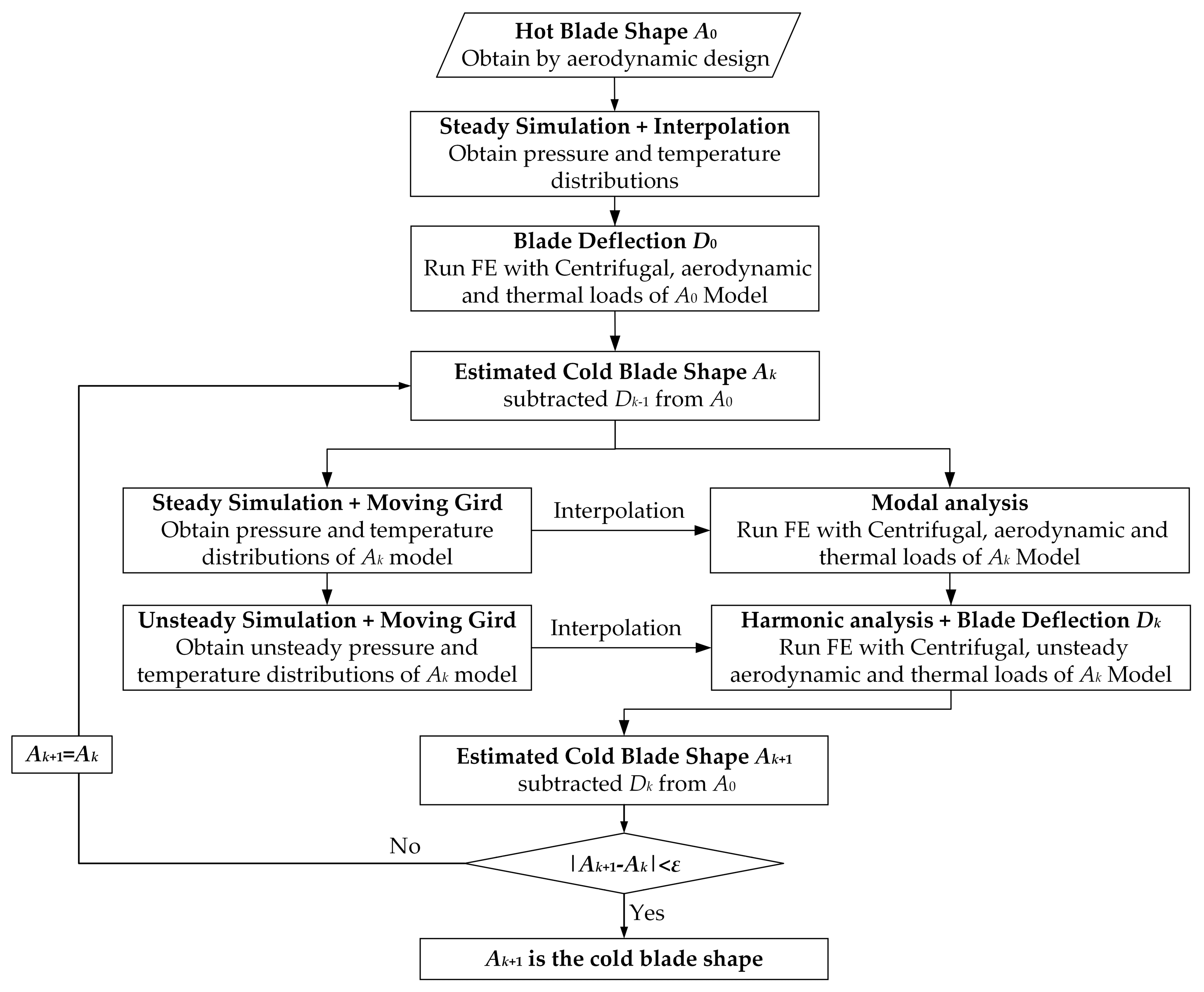
For the SCU method, centrifugal, unsteady aerodynamic, and thermal loads are considered in the hot-to-cold analysis [23], as shown in Figure 8. Modal and harmonic analysis methods are used for calculating unsteady deflections. The damping ratio is given as 0.3% (typical value of the blade) during calculation. Dynamic moving grid technique is used to update the fluid mesh. This method is the most accurate method with a huge calculation and is regarded as the benchmark for testing other methods.

2.3.4. Strong-Weak Coupling Method with Steady Simulation (SWCS)

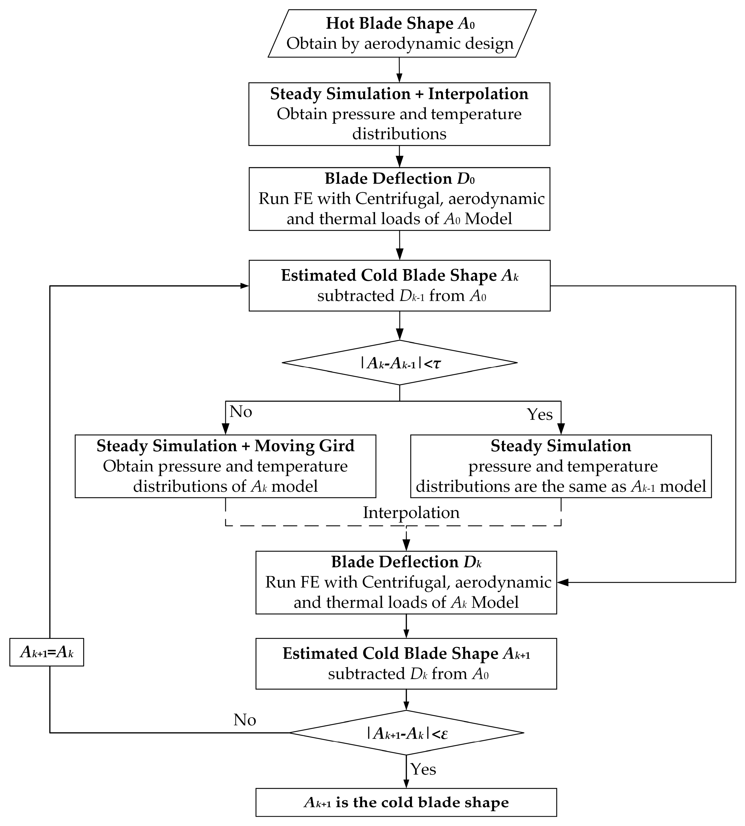
The SWCS method is proposed to properly consider the aerodynamic, centrifugal, and thermal loads in the hot-to-cold analysis. When the blade profile changes violently, the strong coupling between the flow and structural fields is performed to update the pressure, temperature, and deflections. When the blade profile changes slightly, the weak coupling method is used, as shown in Figure 9.

3. Test Case

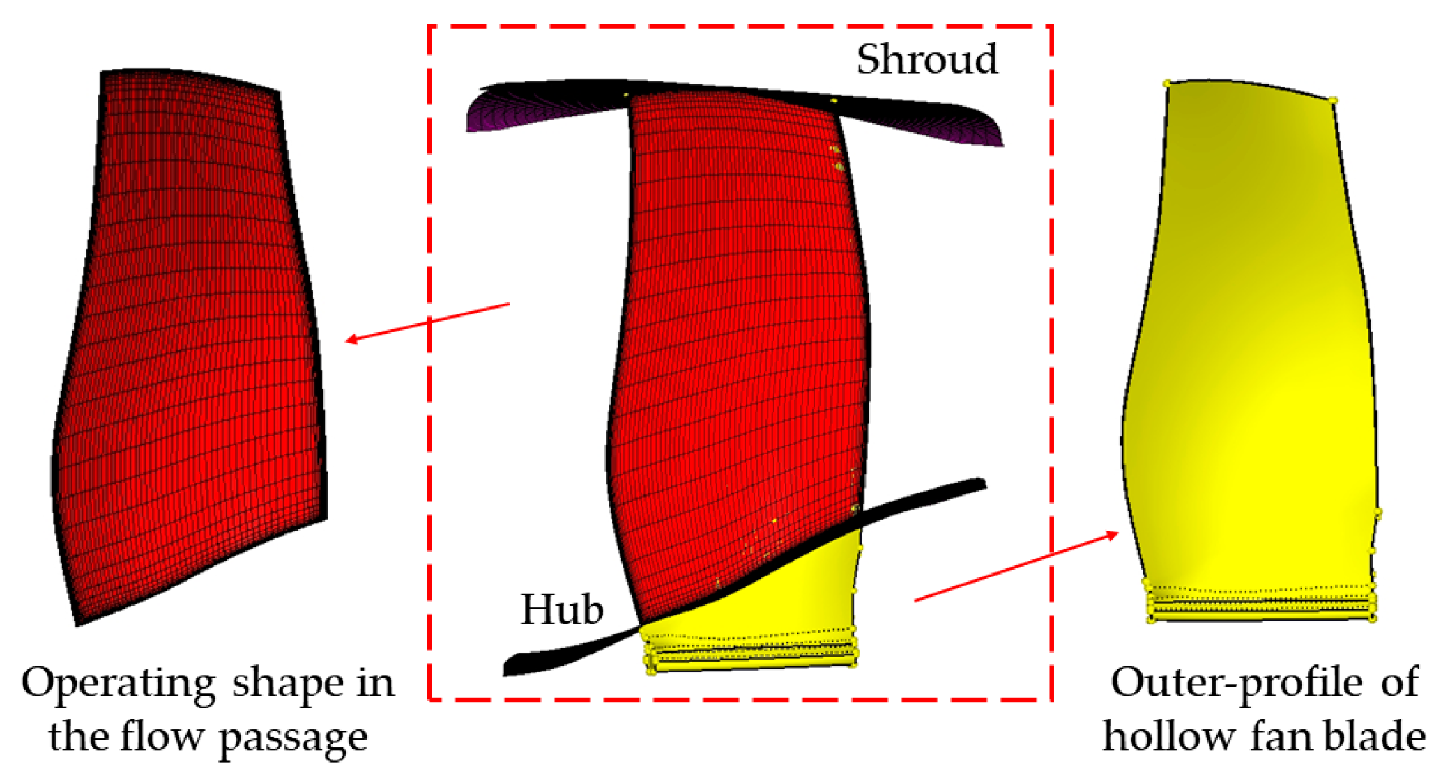
A wide-chord transonic fan blade is studied in this paper, which is partially located in the flow passage and connected with the disk through the tenon/mortise, as shown in Figure 10. The operating shape in the flow passage is determined by aerodynamic design at the design point, and its structural parameters are shown in Table 2. The density of the rotor blade is 4440 kg/m3, the elastic modulus is 109 GPa, and the Poisson’s ratio is 0.34.
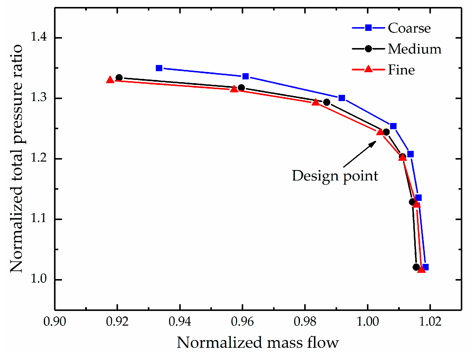
For the flow simulation, the inlet boundary is given as total pressure, total temperature and airflow angle, and the outlet boundary is the mass flow rate. Non-slip and adiabatic wall conditions are set for all walls. The fluid calculation domain is shown in Figure 11. The mesh sensitivity study is performed using three mesh densities with about 310,000 (coarse), 640,000 (medium), and 1,060,000 (fine) nodes per passage. Results show that medium and fine meshes give essentially identical predictions of the aerodynamic performance at the design point, as shown in Figure 12. Considering the computing resources and accuracy, the medium mesh is used for flow simulations with a suitable near-wall thickness for the k–ε turbulence model.

4. Results and Discussions

The results and discussions of the wide-chord fan blade model in Section 3 are presented below. A typical hollow structure is generated according to the parametric modeling method of the hollow fan blade given in Section 2.1 and Section 2.2. Based on this hollow fan blade, the differences between the four hot-to-cold methods (proposed in Section 2.3) are compared, and the reasons for the differences are discussed.

4.1. Modeling of Hollow Fan Blade

The structural parameters of the hollow fan blade are listed in Table 3. Three ribs are uniformly distributed in this model. The wall thickness DR1 ~ DR5 of five hollow sections are given as the percentage of the maximum blade thickness in the corresponding section. The variable wall thickness DC is given as the percentage of the blade thickness in the corresponding position. The parameters M1 and M2 are expressed as the ratio of the distance-to-blade height. According to the request of the fabrication technology, the outermost fillet radius near the leading and trailing edges is 0.5 mm.
Figure 13 shows the FEM of the hollow fan blade and cross sections in the hollow, transition and solid parts. It is divided into 71 elements along the blade height, three elements of the transition part, and adjustable elements according to parameters M1 and M2 of the hollow part. In addition, there are 91 elements along the chordline and eight elements along the thickness direction. Each rib has six elements along the chordline and four elements along the thickness direction. The number of elements is about 60,000 of the hollow fan blade.

4.2. Comparison of Hot-to-Cold Methods

According to the hot-to-cold methods presented in Section 2.3, the cold blade shape can be obtained when the difference between the maximum deformation of two adjacent estimated blades is less than 1%. If the difference is less than 5%, the weak coupling is performed in the SWCS method (after four iterations in this model). The maximum deformation of the blade gradually stabilizes with the increase of the iteration number, as shown in Figure 14. It can be seen that a convergent cold blade is obtained after 12 or 13 iterations. Table 4 lists the maximum deformations of cold blades and the computational effort of four methods. Results show that compared with the SCU method, the prediction error of the UCM method is up to 30% due to the neglect of aerodynamic loads. When the interaction between the structure and flow field is not considered, the prediction error is about 12%, as shown in the WCS method. Obviously, the SWCS method shows a good agreement (error of 2.3%) with the SCU method. It leads to a significant reduction in computing time by a factor of 40 due to considering the aerodynamic variation only in the case of large deformation differences.
A comparison of the hot blade shape and the predicted cold blades by four methods is demonstrated in Figure 15. It presents the difference in blade shape from a three-dimensional perspective, and different colors represent different methods. It can be seen that under the effect of centrifugal and aerodynamic loads, the pre-twisting of the hot blade is weakened compared with the cold blade. The difference between these two shapes is largest at the blade tip and decreases along the blade height, reaching zero at the hub. Greater deformations at the leading edge than at the trailing edge can be observed both in 90% and 50% blade height. The cold blade profiles obtained by SCU and SWCS methods show excellent consistency and lie between the blade shape obtained by UCM and WCS methods.
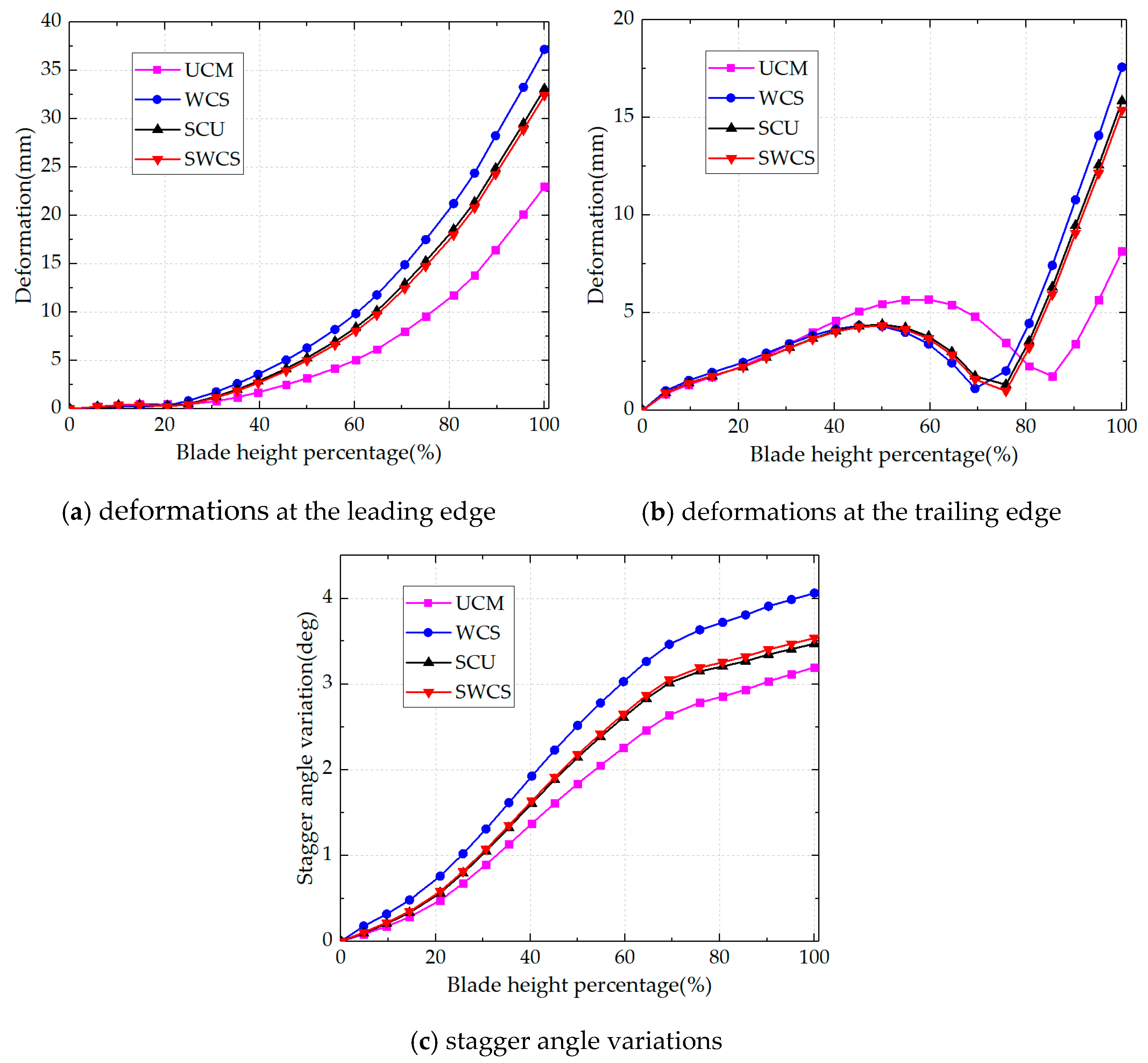
For further comparison, the relative deformations and stagger angle variations along the blade height between the cold and hot blade shapes are presented in Figure 16. The variation trend of the four methods is consistent, which is that deformations at the leading edge increase with the blade height, while that at the trailing edge is non-monotonic. The largest difference between the four methods appears at the blade tip. An excellent agreement can be observed between the SWCS and SCU methods in the whole blade height with an error of 2~5%. In addition, the differences between WCS and SCU methods become larger with the increase of blade height, reaching errors of about 12~20%, above 70% blade height. Unfortunately, the results of the UCM method are seriously deviated from the SCU method, with errors up to 30~40% at the leading edge, 50% at the trailing edge near the blade tip, and 175% at the trailing edge near the 70% blade height.
The deformation of leading and trailing edges results in a change in the stagger angle. The slope of the staggered line is nearly linear at the 20~70% blade height, then decreases, which means that the stagger angles vary uniformly along the blade height. This challenges the validity of the assumption that the stagger angle offset is constantly used in traditional methods to determine the manufacture blade.
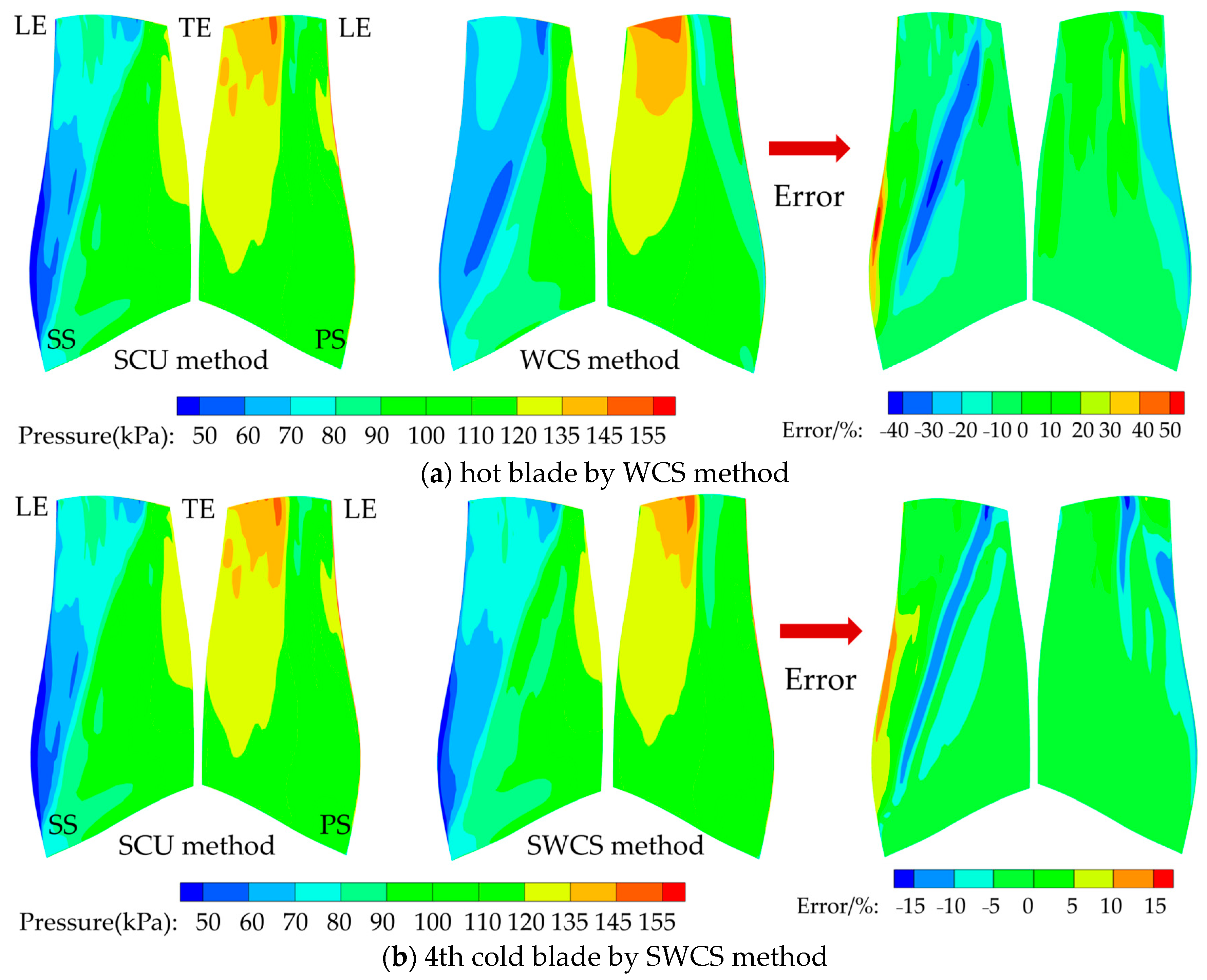
The difference in the prediction results of the above four methods mainly comes from the treatment of aerodynamic loads. In order to explain the reason for such differences, closer attention to the aerodynamic loads on the blade surface is required. Since the temperature gradient on the fan blade surface is small and the deformation caused by thermal loads can be ignored, so the aerodynamic pressure is mainly compared in the following. The influence of blade shape difference on the steady pressure is compared, as shown in Figure 17. The steady pressure distribution of the 13th convergent cold blade in the SCU method is regarded as the benchmark. The result of the WCS method is from the hot blade shape, and that of the SWCS method is from the 4th cold blade.
It can be seen that there are some deviations between the WCS and SCU methods, especially in the suction surface. The difference is ±20% in most areas, except for the leading edge with a maximum error greater than 50%. A better accordance can be observed by the SWCS method, and the error in most areas is in the range of −10% to 5%. This leads to a more accurate prediction of the cold blade shape by the SWCS method compared with the WCS method. This also shows that it is reasonable to ignore the strong coupling between the structure and flow field when the difference in blade shape is small.
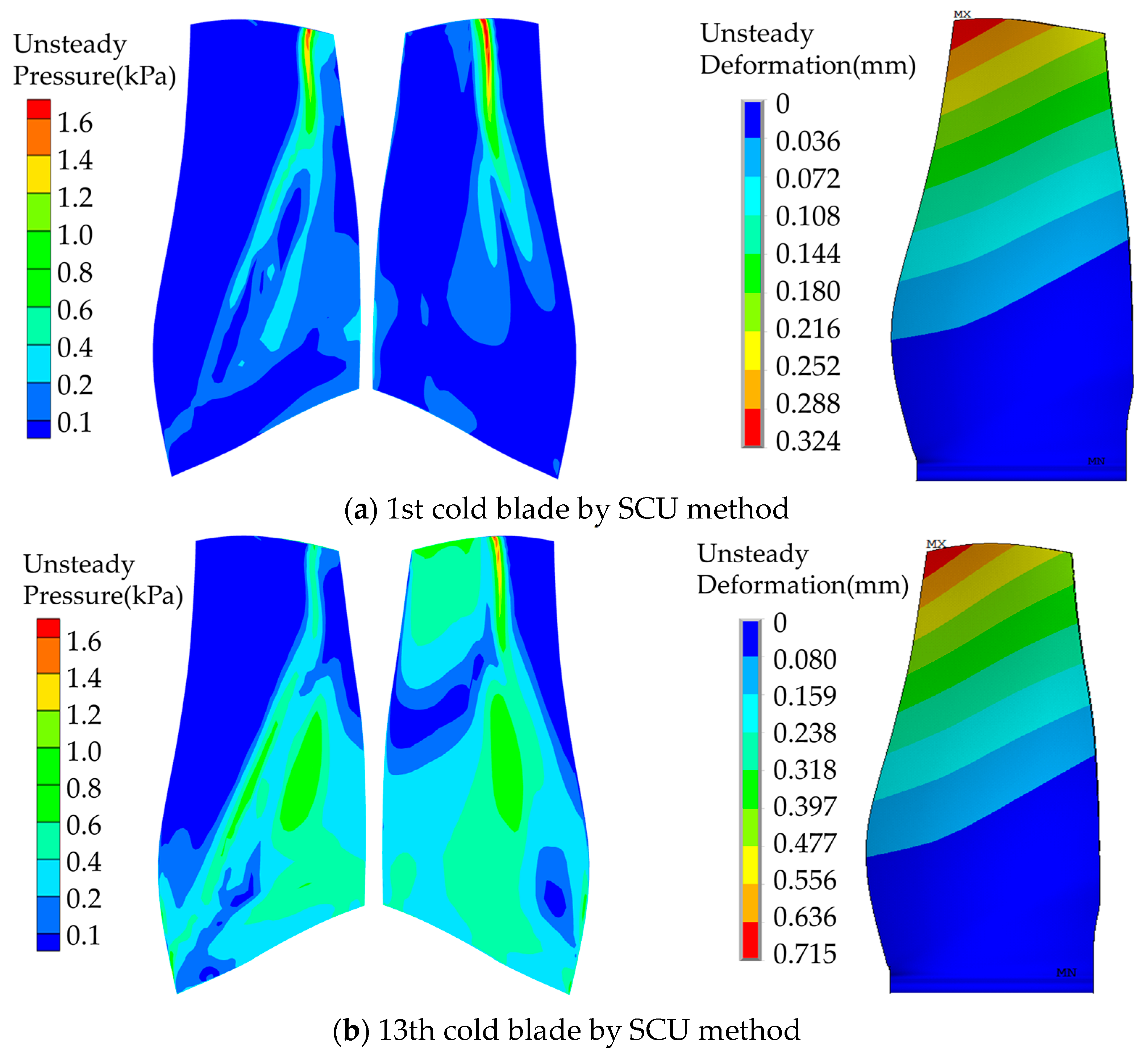
After the comparison of the steady pressure, it is also necessary to clarify the effect of the unsteady simulation. The distributions of the unsteady pressure and deformations from the first and last predicted cold blade by the SCU method are presented in Figure 18. It can be observed that the unsteady pressure is less than 0.5 kPa in most areas due to the lack of wake excitation, which is only 0.5% of the steady pressure. By adjusting the excitation frequency, the first bending mode resonance occurs, and the maximum amplitude is only 0.324 mm for the 1st cold blade and 0.715 mm for the last cold blade. Compared with the deformation (about 33 mm) caused by centrifugal loads and steady pressure, the deformation caused by unsteady pressure can be ignored, which is why the SWCS method can provide similar predictions to the SCU method.
It is an encouraging result because the SWCS method only requires a small amount of steady simulations, while the SCU method needs to perform unsteady simulations in the whole hot-to-cold process. Considering the accurate predictions and the highly reduced computational time, the SWCS method can be applied to quickly predict the manufacture shape of hollow fan blades. It should be noted that the WCS method can also give satisfactory results for solid blades with small deformations. In addition, when the unsteady excitation is large, and the resonance response is significant, the unsteady simulation also needs to be considered. Of course, prominent vibration at the design point will be avoided during design. For the case of large deformation and small vibration of the hollow fan blade discussed in this study, the SWCS method can obtain accurate results.

5. Conclusions

In this study, a strong-weak coupling method with steady simulations (SWCS) is proposed to obtain the manufacture cold blade shape from a given operating hot shape. Aerodynamic loads and deformations are calculated by CFD and structural solvers. The prediction accuracy of the SWCS method is verified using the strong coupling method with unsteady simulation (SCU) as a reference. The computational accuracy and efficiency of the proposed method are also compared with the uncoupling method (UCM) and the weak coupling method (WCS). Before studying the hot-to-cold behaviors, the model parameterization of the hollow fan blade is analyzed. Eight structural parameters are proposed to describe the characteristics of the hollow fan blade. Based on these parameters, an automatic finite element generation method is proposed. An iterative procedure is performed until the estimate of the manufacture blade shape converges.
Numerical results show that the largest differences between the four methods appear at the blade tip. Compared with the maximum deformation predicted by the SCU method (33.19 mm), the result of the UCM method is 22.98 mm with a prediction error of up to 30%. The result of the WCS method is about 37.18 mm with an error of 12%, and that of the SWCS method is 32.44 mm with an error of only 2.3%. Moreover, since only four steady simulations are performed in the SWCS method, the computing time is significantly reduced by 40 times compared with the SCU method, from 7200 min to 180 min, making it possible to conduct the hot-to-cold analysis at the design stage.
The steady pressure of the 4th cold blade shape is in good agreement with those of the 13th cold blade, and the error in most regions is within the range of −10% to 5%. Therefore, it is reasonable of the coupling treatment between the structure and flow fields in the SWCS method. It provides an accurate and rapid method for determining the hollow manufacture blade, which can be used for better structural analysis and better modeling of aerodynamic phenomena.

Author Contributions

Conceptualization, X.Z. and D.H.; methodology, X.Z. and W.C.; validation, D.H.; formal analysis, X.Z.; investigation, X.Z.; resources, D.H. and R.W.; data curation, R.W.; writing—original draft preparation, X.Z.; writing—review and editing, D.H.; supervision, W.C.; project administration, R.W.; funding acquisition, D.H. and R.W. All authors have read and agreed to the published version of the manuscript.

Funding

This study was co-supported by the National Natural Science Foundation of China (No. 52205081 and No. 52022007), the Fundamental Research Funds for the Central Universities, the National Science and Technology Major Project, China (No. 2017-IV-0004-004 and No. J2019-IV-0009-0077).

Institutional Review Board Statement

Not applicable.

Informed Consent Statement

Not applicable.

Data Availability Statement

Not applicable.

Conflicts of Interest

The authors declare no conflict of interest.

References

  1. Fitzgerald, G.; Broughton, T. The Rolls-Royce wide chord fan blade. In Proceedings of the 1st International Conference of the Titanium Products and Applications, San Francisco, CA, USA, 19–22 October 1986; pp. 1–19. [Google Scholar]
  2. Halle, J.; Michael, C. Energy Efficient Engine Fan Component Detailed Design Report; NASA: Washington, DC, USA, 1981; Report No.: NASA-CR-165466. [Google Scholar]
  3. Michael, C. Energy Efficient Engine Shroudless, Hollow Fan Blade Technology Report; NASA: Washington, DC, USA, 1982; Report No.: NASA-CR-165586. [Google Scholar]
  4. Xun, Y.; Tan, M. Applications of superplastic forming and diffusion bonding to hollow engine blades. J. Mater. Process. Technol. 2000, 99, 80–85. [Google Scholar] [CrossRef]
  5. Li, G.; Tan, M.; Liew, K. Three-dimensional modeling and simulation of superplastic forming. J. Mater. Process. Technol. 2004, 150, 76–83. [Google Scholar] [CrossRef]
  6. Zhang, X.; Wang, Y.; Chen, W.; Jiang, X. Parametric study on the flutter sensitivity of a wide-chord hollow fan blade. Chin. J. Aeronaut. 2022, 35, 277–293. [Google Scholar] [CrossRef]
  7. Kosmatka, J.; Mehmed, O. Development of an integral damping treatment for NASA’s next-generation hollow fan blades. In SPIE 4697, Smart Structures and Materials 2002: Damping and Isolation; SPIE: San Diego, CA, USA, 2002; Volume 4697, pp. 15–24. [Google Scholar]
  8. Kosmatka, J. Design and spin testing of integrally damped hollow core composite fan blades. In Proceedings of the 46th AIAA Structures, Structural Dynamics and Materials Conference, Austin, TX, USA, 18–21 April 2005; AIAA: Reston, VA, USA, 2005. Report No.: AIAA-2005-2032. [Google Scholar]
  9. Eberlinc, M.; Širok, B.; Hočevar, M. Experimental investigation of the interaction of two flows on the axial fan hollow blades by flow visualization and hot-wire anemometry. Exp. Therm. Fluid Sci. 2009, 33, 929–937. [Google Scholar] [CrossRef]
  10. Velicki, A. SPF/DB Hollow Core Fan Blade. United States Patent US 5240376, 31 August 1993. [Google Scholar]
  11. McKaveney, C.; Wang, L. Hollow Fan Blade Rib Geometry. United States Patent US 0078703 A1, 28 March 2013. [Google Scholar]
  12. Weisse, M.; McKaveney, C. Hollow Fan Blade Channel Con-Figuration to Reduce Stress. U.S. Patent US 8801367 B2, 12 August 2014. [Google Scholar]
  13. Ogawa, A.; Sofue, Y.; Isobe, T. Structural Analysis of Hollow Blades: Torsional Stress Analysis of Hollow Fan Blades for Aircraft Jet Engines; NASA: Washington, DC, USA, 1979; Report No.: NASA-TM-75718. [Google Scholar]
  14. Kajbyshev, O.; Galimov, A.; Kruglov, A.; Lutfullin, R.; Safiullin, R. Numerical analysis of the hollow fan blade design. Probl. Mashinostraeniya I Nadezhnosti. Mashin. 2004, 2004, 90–95. [Google Scholar]
  15. Kielb, R. Mass balancing of hollow fan blades. J. Eng. Gas Turbines Power 1986, 108, 577–582. [Google Scholar] [CrossRef]
  16. Meng, J.; Liao, L.; Li, D.; Cao, Y.; Yang, L.; Chen, Y. Topology optimization method research on hollow wide-chord fan blade of a high-bypass turbofan engine. Procedia Eng. 2015, 99, 1228–1233. [Google Scholar] [CrossRef]
  17. Ma, Y.; Xu, S.; Liu, H.; Wang, X. Optimization of reinforcing ribs of a hollow fan blade using metamodel-based optimization algorithm. In Proceedings of the ASME Turbo Expo 2016: Turbomachinery Technical Conference and Exposition, Seoul, Republic of Korea, 13–17 June 2016; pp. 1–8. [Google Scholar]
  18. Audic, S.; Berthillier, M.; Bonini, J. Prediction of bird impact in hollow fan blades. In Proceedings of the 36th AIAA/ASME/SAE/ASEE Joint Propulsion Conference and Exhibit, Las Vegas, NV, USA, 24–28 June 2000; pp. 1–7. [Google Scholar]
  19. Hou, N.; Li, Y.; Liu, J. Numerical simulation of bird impact on hollow blades of titanium fan assembly. J. Aerosp. Eng. 2019, 32, 04019044. [Google Scholar] [CrossRef]
  20. Wilson, M.; Imregun, M.; Sayma, A. The effect of stagger variability in gas turbine fan assemblies. J. Turbomach. 2007, 129, 404–411. [Google Scholar] [CrossRef]
  21. Kallesøe, B.; Hansen, M. Some effects of large blade deflections on aeroelastic stability. In Proceedings of the 47th AIAA Aerospace Sciences Meeting Including the New Horizons Forum and Aerospace Exposition, Orlando, FL, USA, 5–8 January 2009. AIAA 2009-839. [Google Scholar]
  22. Fu, Z.; Wang, Y.; Jiang, X.; Wei, D. Tip clearance effects on aero-elastic stability of axial compressor blades. J. Eng. Gas Turbines Power 2015, 137, 012501. [Google Scholar] [CrossRef]
  23. Yang, H.; Zheng, Y. A fluid-structure coupling method for rotor blade unrunning design. In Proceedings of the ASME Turbo Expo 2013: Turbine Technical Conference and Exposition, San Antonio, TX, USA, 3–7 June 2013; pp. 1–10. [Google Scholar]
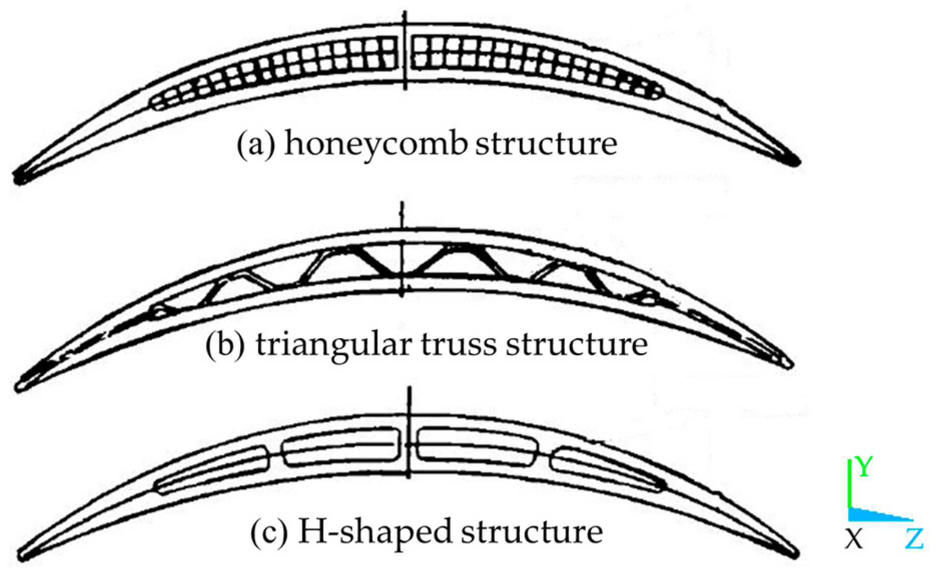
Figure 1. Hollow fan blades with different reinforcing ribs [6].
Aerospace 10 00145 g001
Figure 2. Model parameterization of hollow section.
Aerospace 10 00145 g002
Figure 3. Structural frame of the hollow section.
Aerospace 10 00145 g003
Figure 4. Establishment process of FEM.
Aerospace 10 00145 g004
Figure 5. FEM topologies in the different regions.
Aerospace 10 00145 g005
Figure 6. Flow chart of UCM method.
Aerospace 10 00145 g006
Figure 7. Flow chart of WCS method.
Aerospace 10 00145 g007
Figure 8. Flow chart of SCU method.
Aerospace 10 00145 g008
Figure 9. Flow chart of SWCS method.
Aerospace 10 00145 g009
Figure 10. Model of wide-chord fan blade.
Aerospace 10 00145 g010
Figure 11. Mesh overview of the fluid calculation domain.
Aerospace 10 00145 g011
Figure 12. Aerodynamic performance of three mesh densities.
Aerospace 10 00145 g012
Figure 13. FEM of the hollow fan blade.
Aerospace 10 00145 g013
Figure 14. Variation of maximum deformation with iteration number.
Aerospace 10 00145 g014
Figure 15. Comparison of the hot and cold blades.
Aerospace 10 00145 g015
Figure 16. Relative deformations and stagger angle variations along blade height.
Aerospace 10 00145 g016
Figure 17. Comparison of the pressure distributions by steady simulations, error = (PPSCU)/PSCU.
Aerospace 10 00145 g017
Figure 18. Pressure distributions and deformations of unsteady simulations by SCU method.
Aerospace 10 00145 g018
Table 1. Structural parameters of hollow fan blade.
SymbolStructural ParametersUnitsRanges
Lsymmetry axis position-0 < L< 1
Hrib position-0 < H< 1
DRwall thickness of the equal-thickness sectionmm0 < DR, DC < half of the maximum blade thickness
DCwall thickness of the variable-thickness sectionmm
Brib thicknessmmB > 0
M1distance from the upper boundary of the cavity to blade tipmm0 < M1 < blade height
M2distance from the lower boundary of the cavity to blade rootmm0 < M2 < blade height
Rfillet radiusmmR > 0
Table 2. Structural parameters of wide-chord fan blade.
ParameterValue
Blade number22
Average hub/tip ratio0.34
Average aspect ratio2.13
Average thickness/chord ratio0.06
Tip clearance(mm)0.7
Table 3. Structural parameters of hollow fan blade.
ParameterDR1DR2DR3DR4DR5DCM1M2B(mm)
Value0.160.180.230.250.270.310.150.201.50
Table 4. Comparison of hot-to-cold analysis methods.
MethodMaximum Deformation/mmError/%Computing Time/min
UCM22.9830.75~15
WCS37.1812.03~50
SCU33.190~7200
SWCS32.442.25~180
Disclaimer/Publisher’s Note: The statements, opinions and data contained in all publications are solely those of the individual author(s) and contributor(s) and not of MDPI and/or the editor(s). MDPI and/or the editor(s) disclaim responsibility for any injury to people or property resulting from any ideas, methods, instructions or products referred to in the content.