Article

Parameter Analysis and Experiment Validation of Deployment Characteristics of a Rectangular Tether-Net

1
School of Mechanical Engineering, Nanjing University of Science and Technology, Nanjing 210094, China
2
Aerospace System Engineering Shanghai, Shanghai 201109, China
*
Author to whom correspondence should be addressed.
Aerospace 2023, 10(2), 115; https://doi.org/10.3390/aerospace10020115
Submission received: 12 December 2022 / Revised: 22 January 2023 / Accepted: 24 January 2023 / Published: 25 January 2023
(This article belongs to the Collection Space Systems Dynamics)

Abstract

:
Tether-nets in space applications are flexible capture systems for removing space debris. A new, low-mass, rectangular tether-net deployed by ten towing blocks is proposed in this paper for the purpose of capturing the main body of satellites. The dynamic model of a rectangular tether-net during the deployment process was established. The accuracy of the simulation model was validated by comparing it with on-ground experiments. In addition, the influence of towing block mass and launch speed on the maximum deployment area and the deployment lengths of the long side and short side of the rectangular tether-net were systematically analyzed. The results show that the tether-net configuration and launch distance of the simulations were consistent with those of the experiments, demonstrating the good accuracy of the simulation model. Moreover, with the increase in towing block mass, the maximum deployment area and deployment lengths of both sides of the rectangular tether-net showed a gradually increasing tendence, while the recoil impulse and structural weight increased. When the launch speed of the towing blocks increased, the maximum deployment area and deployment lengths increased significantly and further caused the extension of the shape-preserving distance.

1. Introduction

With space exploration speeding up, the number of on-orbit satellites increases, which increases the risk of spacecrafts being impacted by space debris. According to the information released by the European Space Agency (ESA) at the end of 2020, over 34,000 space debris pieces were greater than 10 cm in size; over 900,000 space debris pieces were in the range of [1 cm, 10 cm]; and around 130 million space debris pieces were between 0.1 cm and 1 cm in orbit [1]. By the end of 2014, over 240 on-orbit spacecraft carrier explosions or impact events had occurred. With the increase in these explosions and disintegration events, more space debris is generated [2]. To remove space debris, many active capturing methods have been proposed. According to their working principles and structural characteristics, these methods can be divided into rigid capturing means [3,4] and flexible capturing means [5,6]. Compared with traditional rigid capture, tether-net systems for space applications possess the features small volume, light weight and longer operating distance [7], which are useful, as well as practical, for capturing space debris [8].
Research on tether-nets has gained fruitful results. Gao et al. [9] established the finite element model of a tether-net using mass–spring–damper elements. The flexible net was modelled as a series of collected semi-damp springs with mass lumped at appropriate nodes. The motion equations of each tether node were developed considering internal elastic force and external forces. Shan et al. [10] established a tether-net dynamic model based on the absolute nodal coordinate method (ANCF). They found that the ANCF model can describe the flexibility of a tether-net better than the mass–spring–damper model, but it requires more calculation time. In addition, compared with the results of the microgravity test, it was found that the mass–spring–damper model is more accurate in describing the trajectory of tether-net towing blocks, while the ANCF model is closer to the real situation in describing the spatial shape and position of the internal nodes of a tether-net. However, these models are inefficient in solving the deployment of large-deformation and multi-contact tether-nets, and the solving process is more complicated. Golebiowski et al. [5] implemented flexible bodies using the Cosserat rods model. It allows one to simulate flexible threads or wires with elasticity and damping for stretching, bending and torsion. Threads may be combined into structures of any topology; therefore, the model is able to simulate nets, pure tethers, tether bundles, cages, trusses, etc.
As for self-collision research on tether-nets, Botta et al. [11] used spherical nodes instead of threads to present a preliminary study of self-collision. Other research on the self-collision of large-scale flexible bodies is mostly concentrated on cloth simulation [12,13]. The basic principle is to divide cloth into triangular meshes and realize the simulation of cloth self-collision by detecting the contact relationship between vertices and triangular meshes. Si et al. [14] proposed a line–line self-collision detection algorithm according to the geometric characteristics of a tether-net. Thereafter, combined with the nonlinear collision model, the self-collision process of the tether-net was studied. However, the method mentioned above is not systematic and cannot be used to detect tether-net collision quickly and conveniently.
Regarding the influence of various parameters on the deployment performance of a tether-net, Yu et al. [15] established an analytical model and a finite element model of a square tether-net and then proposed an index to measure the deployment effect of the tether-net. Botta et al. [16] conducted tether-net simulations with and without bending stiffness; then, the influence of bending stiffness on deployment performance was discussed. They [17] also analyzed the effects of different parameters, such as the ratio of the corner mass values to the total mass, the initial linear momentum and the direction of the initial velocity vectors. Li et al. [18] compared two different kinds of models of a tether-net and proposed an algorithm for solving the nonlinear dynamic model of the deployment of the tether-net. In addition, the influence of launch angle, launch speed and the equivalent damping of the tether on the deployment effect under different working conditions was discussed. Zhang et al. [19] produced an appropriate initial condition after the analysis of the releasing characteristics, including folding pattern, shooting angle and shooting velocity. However, the tether-nets studied by the abovementioned researchers are generally square and hexagonal nets, with little relevant research on rectangular tether-nets.
The abovementioned researchers focused most of their efforts on capturing targets with the aspect ratio of 1:1:1, but few studies have focused on designing novel net configurations for catching actual targets with solar panels. In this paper, a non-equilateral rectangular tether-net aiming to capture the main body of its target is proposed. Instead of covering the whole structure of the target with axisymmetric nets [20], the rectangular rope net is a more suitable method for capturing objects with solar wings. To study the deployment of this rectangular tether-net, the dynamic model of the tether-net was developed based on the explicit dynamic method, and the accuracy of the model was verified by comparing it to on-ground experiments. Then, the influence of towing block mass and launch speed on the maximum deployment area, as well as the deployment lengths of the long side and the short side, was analyzed.
The structure of this paper is as follows: Section 1 summarizes the relevant research and the main contributions of this work. In Section 2, the dynamic model of a rectangular tether-net is established. In Section 3, the accuracy of the simulation model is verified with a comparison with on-ground experiments. The parameter analysis of the rectangular tether-net is included in Section 4. Section 5 concludes the whole research study.

2. Dynamic Model of the Rectangular Tether-Net

2.1. Overview of the Rectangular Tether-Net

The traditional axisymmetric tether-net covers the whole structure of the target, including its solar panels, while the rectangular tether-net employs a different way to capture debris, i.e., it wraps the main body of the target. Figure 1 shows the capture process of a rectangular tether-net. Compared with the traditional equilateral tether-net [21], the rectangular tether-net captures the main body of the target instead of covering the whole structure, which significantly decreases the area of the tether-net. Once the rectangular tether-net is fully deployed, the middle part of the net interacts with the target, which causes the towing blocks to rotate around the target. The tether-net further intertwines with itself and the main body thanks to the rotational motion of ten towing blocks, which achieves the reliable capture of the target. Since the net only interacts with and captures the main body, the area of the tether-net can be remarkably reduced.

2.2. Model Description

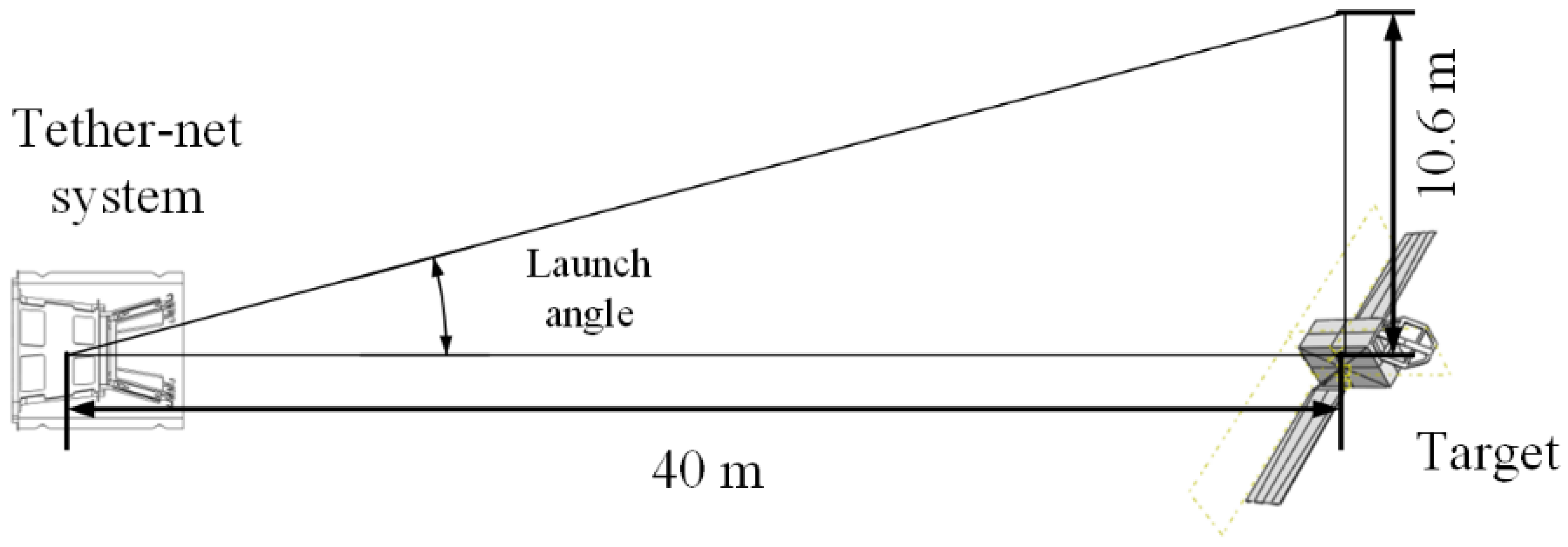
In the present work, a tether-net was designed to be deployed by ten towing blocks, which help the rectangular tether-net be deployed well in both the transverse and the longitudinal directions. The main structure of the rectangular tether-net launching system is shown in Figure 2. The towing blocks were installed in the launcher. Each towing block was fixed with an aluminum baffle, which prevented the towing blocks from falling off from the launch base. As shown in Figure 3, the distance between the target and the launch base was set to 40 m, while the maximum reachable radius of the tether-net after full deployment was set to 10.6 m. According to the parameters in Figure 3, the launching angle, which corresponds to launch angle α between the axis of the towing block and the launch direction, was calculated to be 16° (Figure 2). The initial launching speed and mass of the towing blocks were set to 30 m/s and 170 g, respectively, based on the following considerations: 1. The target had a rotational angular speed of around 15°/s, and the distance between the launch base and the target was 40 m. Because the target was the main body of the debris piece, to prevent the tether-net from hitting the solar panels as the target rotated, the tether-net had to reach the target less than 2 s after launching. 2. The towing blocks had to possess enough kinetic energy to pull out the tether-net and deploy it during flight. 3. The recoil force generated by launching had to remain at a low level to protect the launch base, which set the upper limit of launching speed and mass of the towing blocks. 4. The total structural mass had to be small, which limited the mass of the towing blocks.
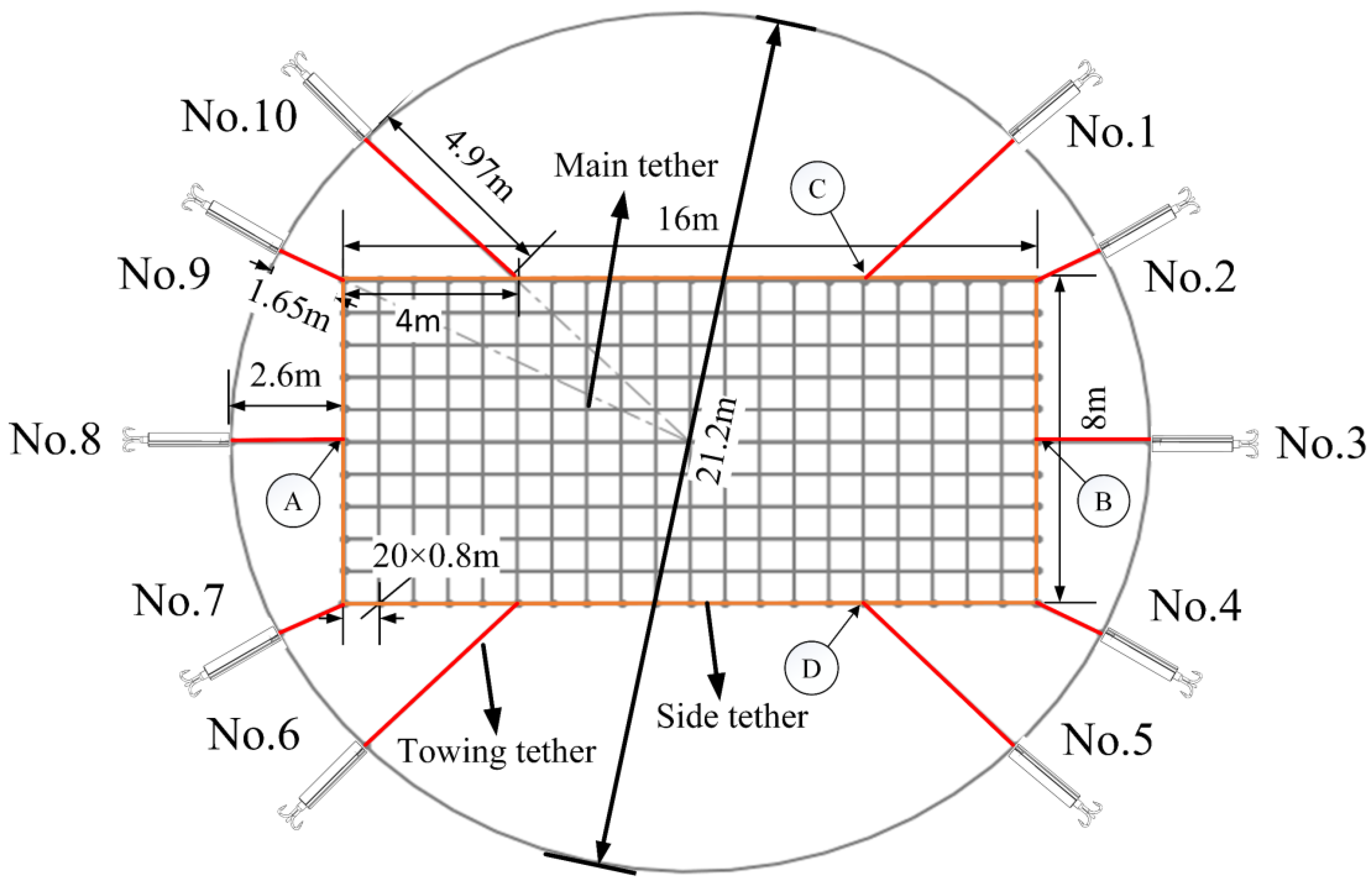
The launcher was installed on the launch base, which could attenuate the recoil impulse transmitted to the platform. The flexible net was stored in the net cabin outside of the launcher. Since the rectangular tether-net is non-equilateral, the ten towing blocks were not in a uniform circumferential arrangement. To obtain the fully extended state of the rectangular tether-net shown in Figure 4, the position of each towing block was specially arranged as can be seen in Figure 2, with different lengths of the towing tethers. The angle between towing block No. 1 and towing block No. 3 was set to 45°, while the angle between towing block No. 2 and towing block No. 3 was 26.5°. The other towing blocks were symmetrical with respect to Nos. 1, 2 and 3 along the central axis.
The configuration of the rectangular tether-net is shown in Figure 4. The size of the tether-net was 16 × 8 m, and the size of each square grid was 0.8 m × 0.8 m. Ten towing tethers with different lengths were arranged along the circumference of the tether-net, connecting the towing blocks with the tether-net. In the fully deployed state of the tether-net, the towing blocks were distributed in a circle with a diameter of 21.2 m. The parameters for the rectangular tether-net dynamic model are summarized in Table 1.

2.3. Establishment of the Tether-Net Dynamic Model

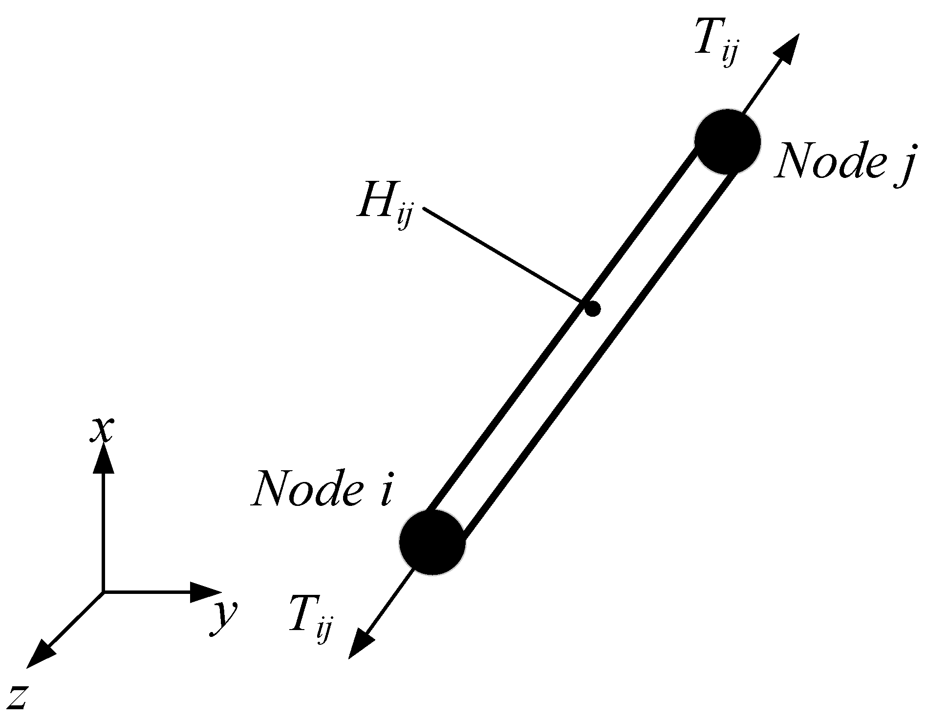
The T3d2 element (two-node, linear, three-dimensional truss element) in ABAQUS was selected [22] to construct the rectangular tether-net model. The truss elements in the finite element model were connected with element nodes. When the truss elements are under compression loading conditions, they rotate around the nodes freely to avoid the effect of compression loads. Therefore, multiple truss elements connected by element nodes could simulate the dynamics performance of tethers. Additionally, each truss element can bear internal and external forces during movement. The dynamic model of the rectangular tether-net system consists of a set of dynamic equations for single truss elements [23]. Figure 5 shows the force transmission of the truss elements in the deployment process. The truss element is a double-node element (node i and node j), as a two-node linear three-dimensional truss element used for modeling truss structures in space. It has six degrees of freedom per node, allowing for deformations in all three dimensions. It is ideal for modeling truss structures because it can handle large deformations and compressive loads well, and unit axial force Tij of the element can be calculated as follows:
T i j = k i j ( l i j l i j 0 )
where lij is the deformed length of truss element Hij, parameter l i j 0 is the initial length of the truss element and kij is the equivalent stiffness of the truss element, which depends on the material of the net tether (Aramid III, in this study). The equivalent stiffness (kij) is calculated as
k i j = E A i j l i j 0
where E is the elastic modulus of the tether material and Aij is the cross-sectional area of the tether.

2.4. Contact between Net Tethers

When two tethers make contact, the non-penetration condition for the contact is set to prevent penetration between different net tethers. In Figure 6, ΩA and ΩB are the current configurations of two tethers. BA and BB are the boundary surfaces. x p t is the coordinate of a specified point P on boundary surface BA at time t. dt is used to represent the distance between point P and point Q (Figure 6) on boundary surface BB, which can be expressed as
d t = d ( x P t , t ) = | x P t x Q t |
In order to satisfy the non-penetration condition, for random point P on boundary surface BA, the formula needs to be modified as follows [24]:
d n t = d ( x p t , t ) = ( x p t x Q t ) n Q t 0
where subscript n of d n t represents the distance along the normal direction, n Q t is the unit normal vector at point Q on boundary surface BB at time t, d n t > 0 indicates the separation of P point and surface BB, and = 0 indicates that point P is in contact with surface BB during the collision of tethers. Given that Equation (4) should be valid for random points on the contact surface, the requirement of the non-penetration condition is given as
d n t = d ( x ( A ) t , t ) = ( x ( A ) t x ( B ) t ) n ( B ) t 0
According to the law of action and reaction, the resultant force of two tethers on the contact surface is zero.
t N A + t N B = 0 t T A + t T B = 0
Here, t N A and t N B are the normal contact forces of tether A and tether B at the contact point, respectively; and t T A and t T B are the tangential contact forces of tether A and tether B at the contact point, respectively.
The normal contact force can only be pressured in the normal direction, and its condition is expressed as
t n B = t N B n B 0 t n A = t N B n B 0
The tangential contact force represents the friction force. It can be expressed as
t T A η t N A
where η is the coefficient of friction. When t T A = η t N A , there is tangential relative sliding between the contact surfaces; the direction of the tangential contact force can be expressed as
τ = v ¯ T v ¯ T = v T A v T B v T A v T B
where v ¯ T is the relative sliding velocity in the tangential direction.

2.5. Solution of the Tether-Net Dynamic Model

In this work, the ABAQUS/Explicit algorithm was used to solve the nonlinear deployment process of the rectangular tether-net. The solution procedure is summarized below.
Step 1: Node calculation
The acceleration of a node is obtained by solving the following dynamic equilibrium equation:
u ¨ ( t ) = ( M ) 1 ( P ( t ) I ( t ) )
where u ¨ ( t ) represents the acceleration of the node at time t, M is the mass matrix of the node, P ( t ) is the external force applied to the node and I ( t ) is the internal force of the element. The acceleration is explicitly integrated over time with the central difference method to solve the velocity and displacement through the following equations:
u ˙ ( t + Δ t 2 ) = u ˙ ( t - Δ t 2 ) + Δ t ( t + Δ t ) + Δ t ( t ) 2 u ¨ ( t )
u ( t + Δ t ) = u ( t ) + Δ t ( t + Δ t ) u ˙ ( t + Δ t 2 )
where u ˙ is velocity and u is displacement of the node. Subscript t refers to the increment number, and t + Δ t / 2 and t Δ t / 2 refer to the mid-increment values.
Step 2: Element calculation
The velocities at the midpoint of each incremental step are used to determine element strain rate ε ˙ [18].
ε ˙ i ( t + Δ t ) = u ˙ j ( t + Δ t 2 ) u ˙ i ( t + Δ t 2 ) l i j
here, u ˙ i and u ˙ j are the velocities of node i and node j, respectively, as shown in Figure 5.
Element strain increment d ε is calculated based on element strain rate.
d ε = ε ˙ d t
Element stress σ ( t + Δ t ) is calculated based on the material constitutive relationship. For linear elastic materials, the element stress is the product of elastic modulus E and strain ε ( t + Δ t ) . It can be further obtained as
ε ( t + Δ t ) = ε ( t ) + d ε
σ ( t + Δ t ) = E ε ( t + Δ t ) = E ( ε ( t ) + d ε )
Then, node internal force I t + Δ t can be calculated as follows:
I ( t + Δ t ) = A e σ ( t + Δ t )
where Ae is the cross-sectional area of the element.
Step 3: Proceed to the next time interval and return to step (1) until the simulation time is reached.
When applying the explicit method to solve a specific problem, the time step must be smaller than the stability time limit; otherwise, numerical instability is generated, and the solution fails to converge. The stabilization time is determined by the highest-order natural frequency of the system, and the stability condition is
Δ t Δ t stable = 2 ω n
where Δ t is the time step, Δ t stable is the stability time limit and ω n is the highest-order natural frequency of the system. The natural frequency of the smallest element in the system can be substituted with the actual highest-order natural frequency, because the natural frequency of the smallest element is often higher than the highest-order natural frequency of the entire model [25]. Based on this, the stable time limit can also be defined as
Δ t stable = L e ρ E
where Le is the minimum element size, E is the elastic modulus and ρ is the material density. In the simulation model, the smallest element was on the side tether, and the value of Δ t stable was calculated to be 0.017 s. According to Equation (18), time step Δ t was set to 0.01 s.

2.6. Elastic Moduli of Net Tethers

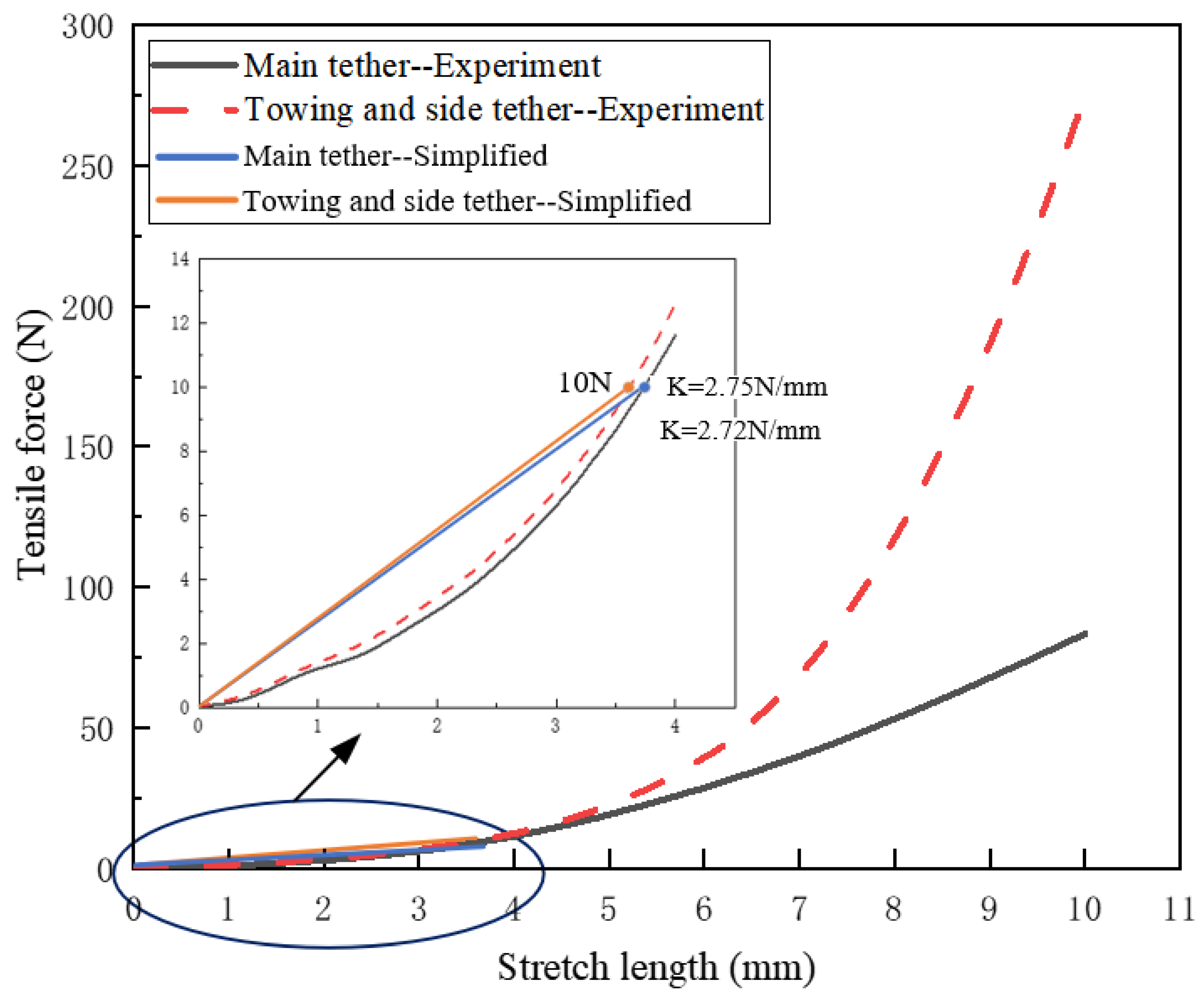
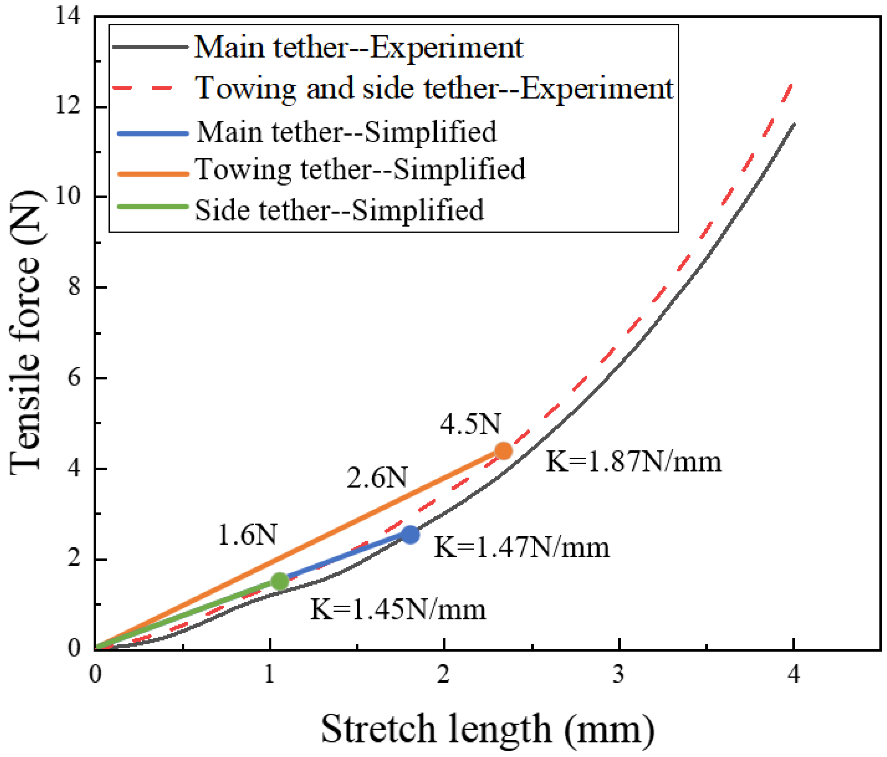
The rectangular tether-net is shown in Figure 4, including main tethers, towing tethers and side tethers. Tensile stiffness tests were carried out on Aramid III tethers with a diameter of 0.5 mm and a diameter of 2 mm. The tests were carried out on a SANS testing machine from the National Defense Key Laboratory in Nanjing University of Science and Technology. The measured force range was between 1 kN and 100 kN, and the precision of force indication could be achieved within ±1%. Before the tests, both ends of the tethers were tied to the upper and lower grippers of the testing machine, and the tethers were in a relaxed state. During the tests, the tethers were stretched, with the displacement and force sensors recording the real-time distance and tensile force. The initial length of each tether was 100 mm, and the maximum strain in the tests was set to 0.2. The results of tensile stiffness tests on net tethers are shown in Figure 7. The net tether stiffness of the two specifications increased with the increase in external load. However, when the external load was under around 10 N, the relationship between the net tether stiffness and elastic modulus of the net material could be simplified as linear, as shown in Equation (2), without impacting the precision of the calculation. The equivalent areas (Aij) of the two different types of net tethers were calculated to be 0.196 mm2 and 3.14 mm2, respectively; l i j 0 indicates the initial length of the tether (100 mm) in the tensile experiments.
The procedure of tether stiffness determination is described in the following: Firstly, define the initial maximum tension of the tether segment; subsequently, determine the constant tensile stiffness based on the tensile properties (Figure 7). Afterwards, execute the dynamic model of tether-net deployment, and obtain the new maximum tension during deployment. Finally, reselect the new tensile stiffness. Repeat the steps mentioned above until the maximum tension between two iterations is lower than 0.1 N. Then, determine the current tensile stiffness as the ultimate tether stiffness for subsequent analysis. The iterative flowchart is reported in Figure 8.
The initial maximum tension of the tether segment was firstly defined as 10 N, in which the stiffness of the main tethers was 2.72 N/mm and the stiffness of the towing tethers and side tethers was 2.75 N/mm. The elastic modulus of the main tethers was calculated, using Equation (2), to be 1385.3 MPa, and the elastic moduli of the towing tethers and side tethers were 87.5 MPa. Based on Figure 8, the iteration was performed to obtain the tensile stiffness values of the main tethers, towing tethers and side tethers. After eight iterations, the ending condition was satisfied, and the whole loop was finished. The final force curves of different kinds of tethers during deployment are shown in Figure 9. The results reveal that the maximum tension of the main tethers was 2.6 N, that of the towing tethers was 4.5 N and that of the side tethers was 1.6 N. Therefore, the stiffness values of the main tethers, towing tethers and side tethers were selected as 1.47 N/mm, 1.87 N/mm and 1.45 N/mm, respectively. The chosen stiffness is marked in Figure 10, and the time for maximum tension appeared to be in the range of 1.28~1.57 s. Under these conditions, the tether-net was fully deployed, and most tethers were in a straightened state. The elastic moduli of the main tethers, towing tethers and side tethers were obtained using Equation (2) and are summarized in Table 2. The computed elastic moduli were equivalent for the corresponding structures and could be applied to the overall net tether structure.

2.7. Interior Ballistics of the Tether-Net System

The launching of the rectangular tether-net was powered by the burning of propellant. Considering the safety of the system, the maximum chamber pressure needed to be calculated; this could be obtained by calculating the internal ballistics of the launcher. The ten towing blocks shared a single launch chamber. Therefore, with the equivalent principle, we equated the ten towing blocks to one, and the multiple launch chambers could be considered to be a single chamber. According to the rule of parameter equivalence, the total mass of the towing blocks was expressed as the sum mass of ten towing blocks. The total cross-sectional area of the launch chamber was equal to the sum of the ten cross-sectional areas. Each launch chamber and towing block were fixed with an aluminum baffle.
To obtain the interior ballistic data of the launcher, the equivalent launch model was designed by adopting the classical interior ballistic equation, which is shown below [26]:
ψ = χ Z 1 + λ Z + μ Z 2 d Z d t = μ 1 e 1 p n φ m d v d t = S p d l d t = v S p l ψ + l = f ω ψ k 1 2 φ m v
where ψ is the burned propellant percentage; χ , λ and μ are the shape characteristic quantities of the propellant; Z is the relative thickness of the propellant that has burned; t is the time in which the propellant burns; μ 1 is the coefficient of the burning rate; e 1 is the arc thickness of the main charge propellant; p is the chamber pressure; n is the burning rate–pressure exponent; φ is the secondary work coefficient; m is the mass of the towing blocks; v is the speed of the towing blocks; S is the cross-sectional area of the launch chamber; l is the travel length of the towing blocks in the launch chamber; l ψ is the equivalent length of the initial volume of the launch chamber; f is the gunpowder force; ω is the mass of propellant; and k is the specific heat ratio.

3. Experimental Validation

3.1. Prototype Design

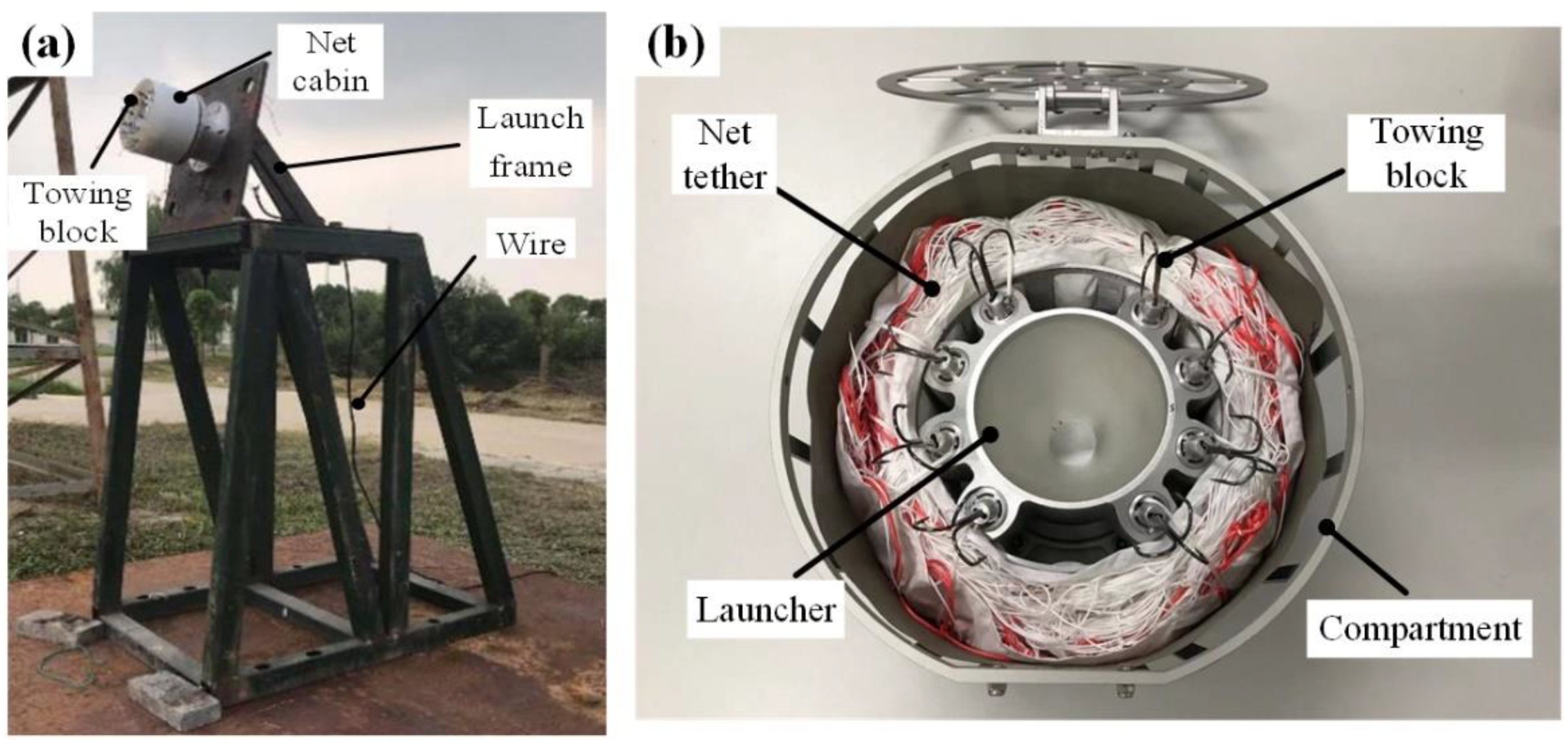
To verify the correctness of the parameters, the modeling method, the tether material and the solving algorithm, on-ground experiments were carried out to lay the foundation for subsequent parameter analysis in space. The setup of the experiment and the launcher of the tether-net are shown in Figure 11. It can be observed in Figure 11a that the launcher was connected to the launch base through shock-absorbing bolts, while the launch base was fixed to the launch frame with screws. Moreover, there was an upward angle between the launch direction and the horizontal direction to prevent the net from touching the ground due to gravity. The rectangular tether-net was stored in a net cabin. During the deployment experiment, the electric primer at the bottom of the launcher was ignited remotely, burning the gunpower and generating high-pressure gas. Subsequently, the ten towing blocks were immediately ejected to deploy the rectangular tether-net. Figure 11b shows the launcher of the tether-net. The launch base was installed in the compartment through the threaded hole at the bottom. The tether-net was stored within the annular space between the launcher and the compartment. There was a hatch on the top of the compartment, which is generally closed and unfolded by the electronic control system before launching the tether-net. It is notable that the compartment was not used, and the launch base was directly installed on the launch frame during the experiment. Ten towing blocks were circumferentially distributed with hooks mounted on the tip. The ignition command was sent out when the launch conditions of the platform were satisfied; then, 10 towing blocks were thrown out synchronously at designed speed with the pushing force of the pistons. The rectangular tether-net was further deployed by the towing blocks.

3.2. Comparison of Simulations and Experiments

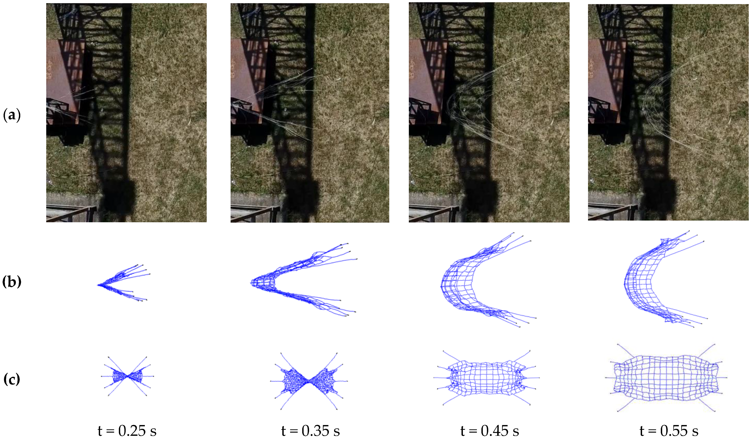
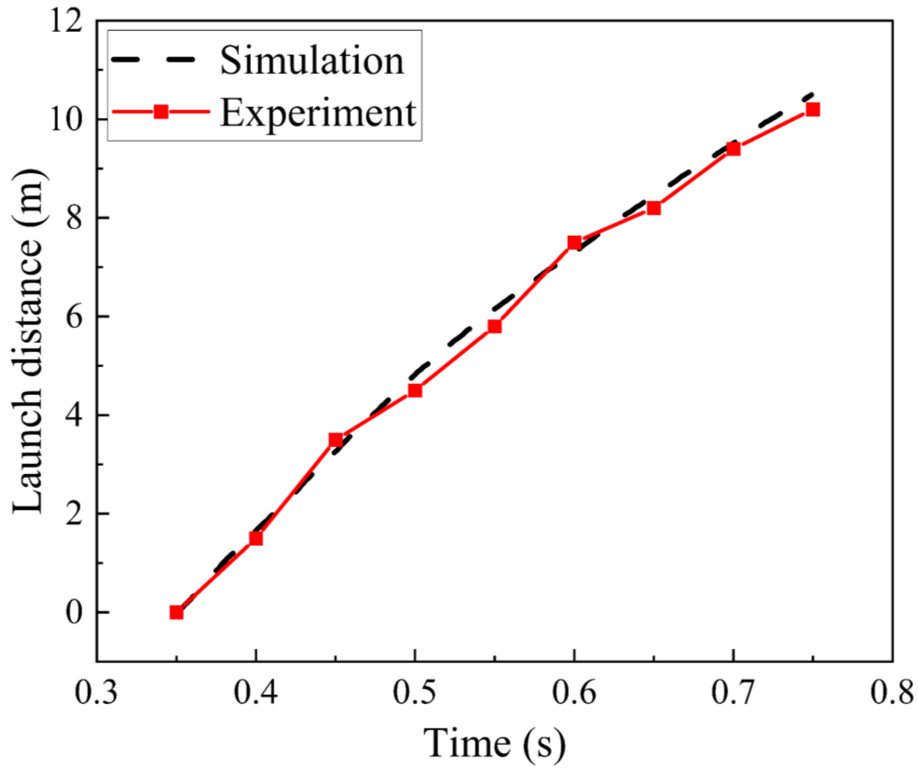
The on-site photos of the on-ground experiments and the corresponding dynamic simulation results are shown in Figure 12. The configuration of the tether-net at different times and the launch distance from the center point of the tether-net were obtained. The comparison of launch distance between simulation and experiment is illustrated in Figure 13.
It can be measured in Figure 12 and Figure 13 that the maximum deviation in the launch distance between simulations and experiments was 0.38 m. To support the quantitative comparative analysis of experiments and simulations, the relative root mean square (RMS) value of the response residuals (RRMS) [27] was defined as
R R M S = 1 m i = 1 m ( U mod ( t i ) U exp ( t i ) ) 2 1 m i = 1 m U exp 2 ( t i )
where U m o d t i represents the simulated data, U e x p t i represents the experimental data and m is the number of recorded sampling time instants ti. The calculation result was 3.55%, which is acceptable.
In general, the simulation results basically matched the test results in terms of trends and magnitudes, validating the accuracy and reliability of the dynamic model. This provided a solid foundation for the subsequent parameter analysis of deployment performance.

4. Parameter Analysis of the Rectangular Tether-Net

4.1. Deployment Performance of the Rectangular Tether-Net

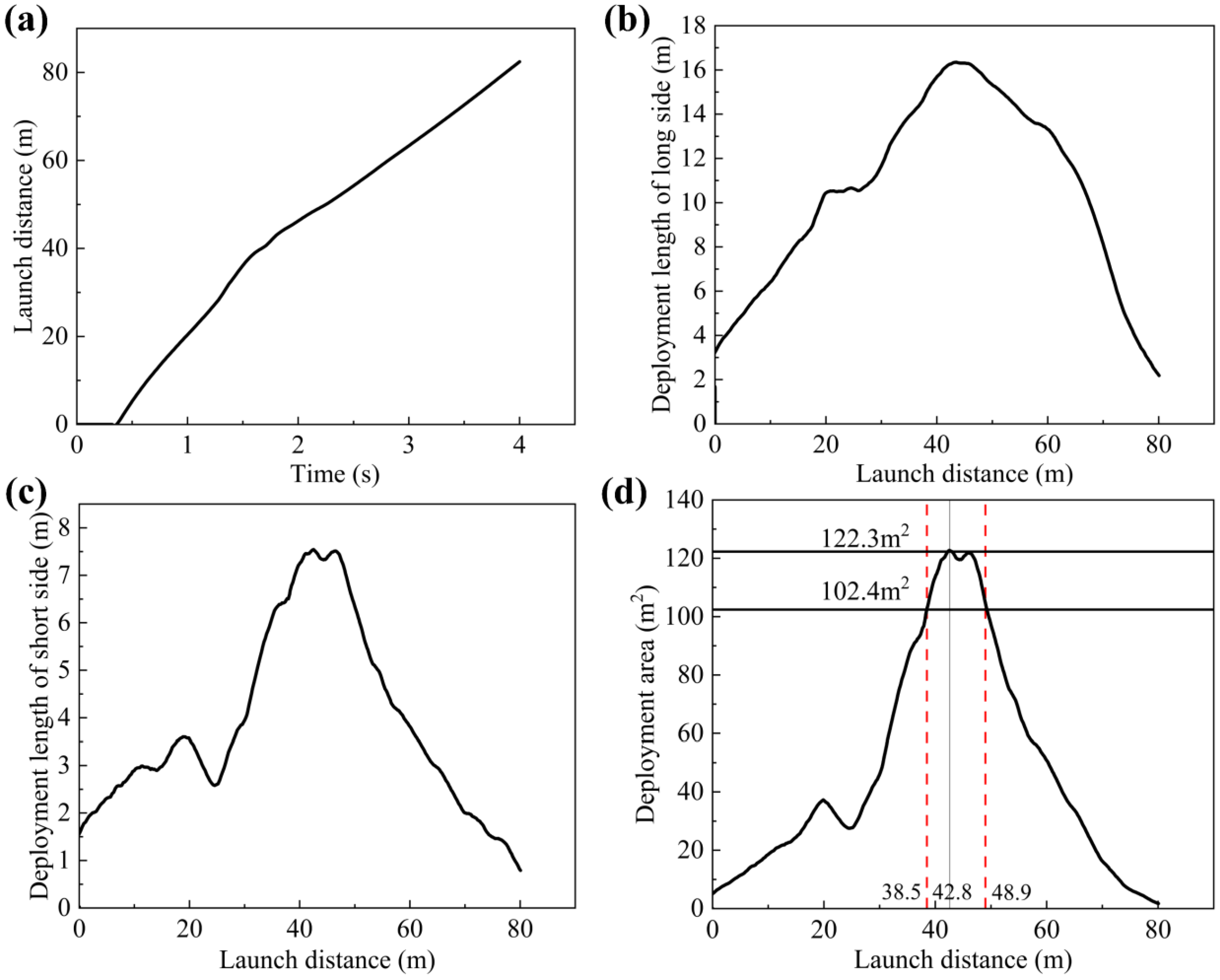
As shown in Figure 4, several indices were firstly introduced to evaluate the deployment characteristics of the rectangular tether-net: 1. Deployment length of long side: real-time distance between point A and point B during the deployment of the rectangular tether-net. 2. Deployment length of short side: real-time distance between point C and point D during deployment. 3. Maximum deployment area: maximum area of quadrangle formed by points A, B, C and D during deployment. 4. Deployment distance: launch distance of the tether-net when the maximum deployment area is reached (the launch distance represents the displacement of the tether-net center point along the launching direction). 5. Shape-preserving distance: range of launch distance where the deployment area is greater than 80% of the theoretical deployment area limit. The theoretical limit deployment area of the rectangular tether-net was 16 m × 8 m = 128 m2. Therefore, the shape-preserving distance was defined as the range of launch distance where the deployment area was over 102.4 m2. Once the dynamic model was established, the simulation of the rectangular tether-net system in the space environment was carried out. The configurations of the tether-net during deployment with the initial parameters are shown in Figure 14, the curves reflecting the deployment performance of the tether-net are shown in Figure 15 and the deployment parameters of the tether-net are shown in Table 3.
As shown in Figure 15 and Table 3, the maximum length of the long and short sides of the rectangular tether-net reached 16.3 m and 7.5 m at the launch distances of 43.0 m and 42.5 m (Figure 15a–c), respectively. The maximum deployment area (Figure 15d) was 122.3 m2 at the launch distance of 42.8 m, and the maximum expansion rate of the tether-net reached 95.6%. The deployment distance was 42.8 m around 1.8 s after launching, and the range of the shape-preserving distance was 38.5~48.9 m. Additionally, the deployment area gradually increased from 0.0 m2 to 122.3 m2 at first and then decreased to 1.5 m2 due to the rebound of the tether-net. Therefore, with the current imposed parameters, the optimal distance between the launcher and the target should be selected as 42.8 m. Additionally, towing blocks 1, 5, 6 and 10 moved at the highest speed, followed by towing blocks 3 and 8, while towing blocks 2, 4, 7 and 9 were the slowest ones. This was due to the different weight of the tether-net driven by each towing block, with the tether-net driven by towing blocks 1, 5, 6 and 10 being the lightest.
We then calculated the displacement curves of all towing blocks; according to the symmetry of the tether-net, as long as the displacement of towing blocks 1, 2 and 3 was output, the results below were obtained (Figure 16).
As can be seen in Figure 16, towing block 1 showed the highest speed among the three different towing blocks, while towing block 2 was the slowest under both conditions. This was due to the small size of the mass of the tether-net driven by towing block 1, which was the smallest compared with the others. In general, the discrepancy in the displacement of different towing blocks had a few impacts on the deployment performance of the rectangular tether-net. In addition, it can be seen from the black diagonal line in Figure 16a that all the towing blocks moved faster than the center of the tether-net except for towing block 2, which moved slower than the center of the tether-net when the launch distance ranged from 35 to 44 m in the corresponding time range of 1.47~1.85 s.
The mass and launch speed of the towing blocks are two important parameters in flexible tether-net systems. Therefore, their influence on the deployment performance was further studied.

4.2. Influence of the Mass of Towing Blocks

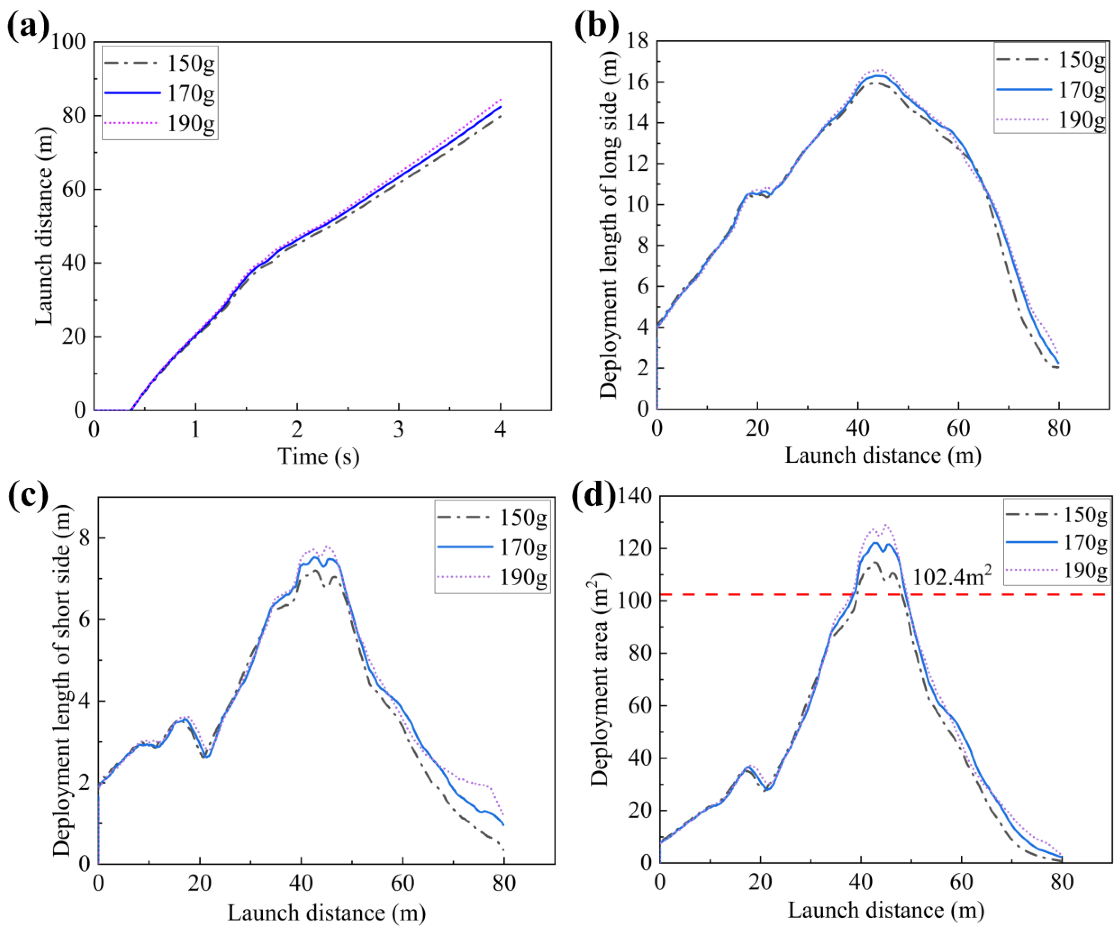
The mass of the towing blocks plays an important role in tether-net deployment. It affects the recoil force and impacts its transmission to the base structure. Therefore, it is necessary to select an appropriate mass value of the towing blocks for achieving the best deployment performance. In this section, the mass values of the towing blocks were chosen as 150 g, 170 g and 190 g to explore their influence on the dynamic responses of the tether-net. The results are shown in Figure 17 and Table 4.
Figure 17 and Table 4 present that with the increase in towing block mass from 150 g to 190 g, the maximum deployment area increased from 114.3 m2 to 128.7 m2. The maximum deployment lengths of the long and short sides increased from 16 m and 7.2 m to 16.6 m and 7.8 m, respectively. In addition, with the increase in towing block mass, the deployment distance and the shape-preserving distance were maintained around 42.4 m and in the range of 38.7~48.9 m, respectively. Based on the above results, it was concluded that as the mass of the towing blocks increased, better deployment performance of the tether-net was achieved. However, the propellant mass increased if the same launch speed was maintained, and this increased the chamber pressure and recoil force.
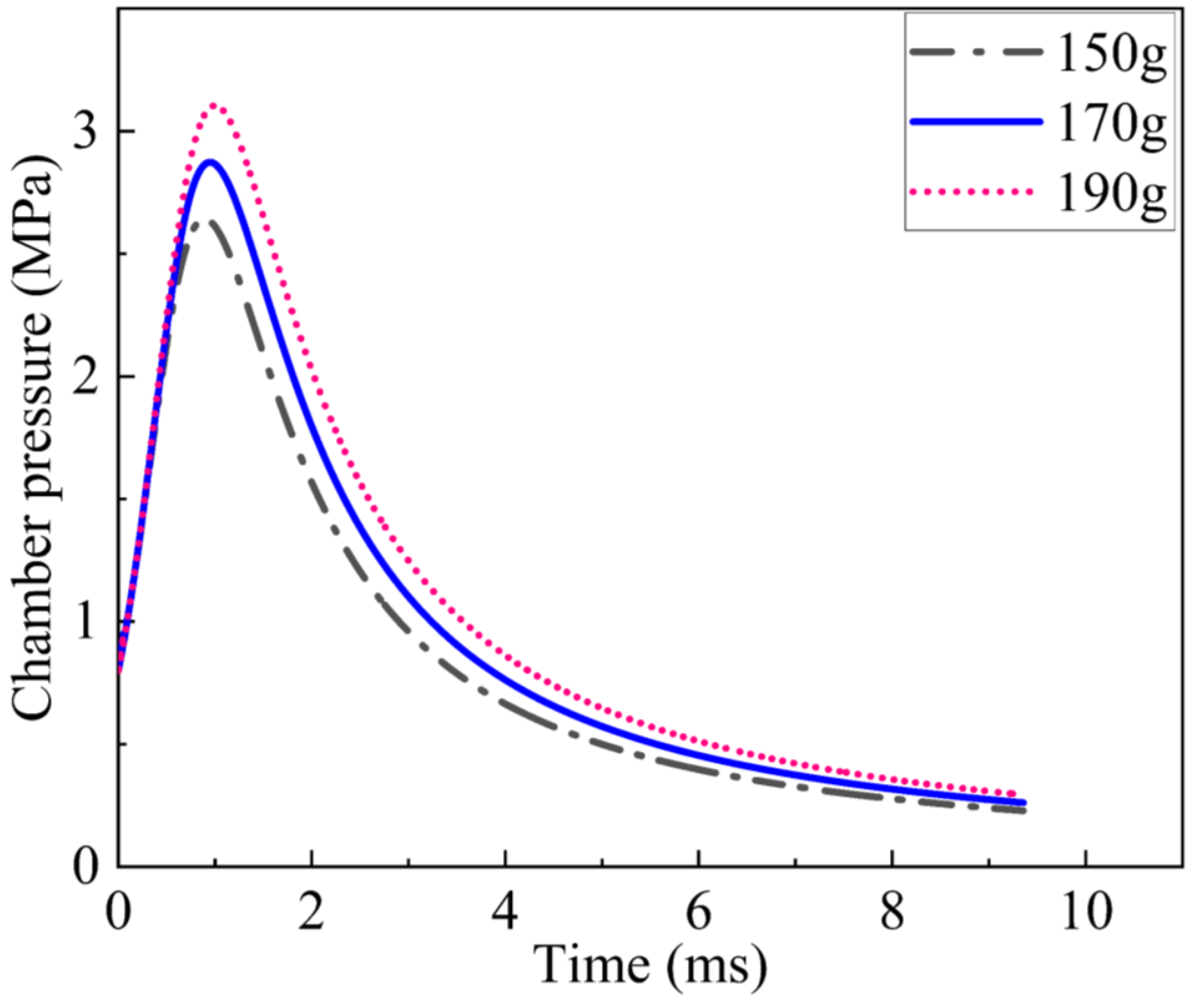
The chamber pressure during launch was calculated with three different towing block mass values using Equation (20), and the results are shown in Figure 18.
As shown in Figure 18, with the increase in towing block mass from 150 g to 190 g, the maximum chamber pressure gradually increased from 2.6 MPa to 3.1 MPa. The recoil impulse generated by the launch of the towing blocks can be calculated as follows:
I = m v = m v v cos α
where m is the total mass of the towing blocks and v v is the launch speed of the towing blocks.
Additionally, based on Equation (22), the recoil impulse transmitted to the launch base increased from 4.3 Ns to 5.5 Ns with the increase in towing block mass from 150 g to 190 g, which further caused an increase in structural weight.

4.3. Influence of the Launch Speed of Towing Blocks

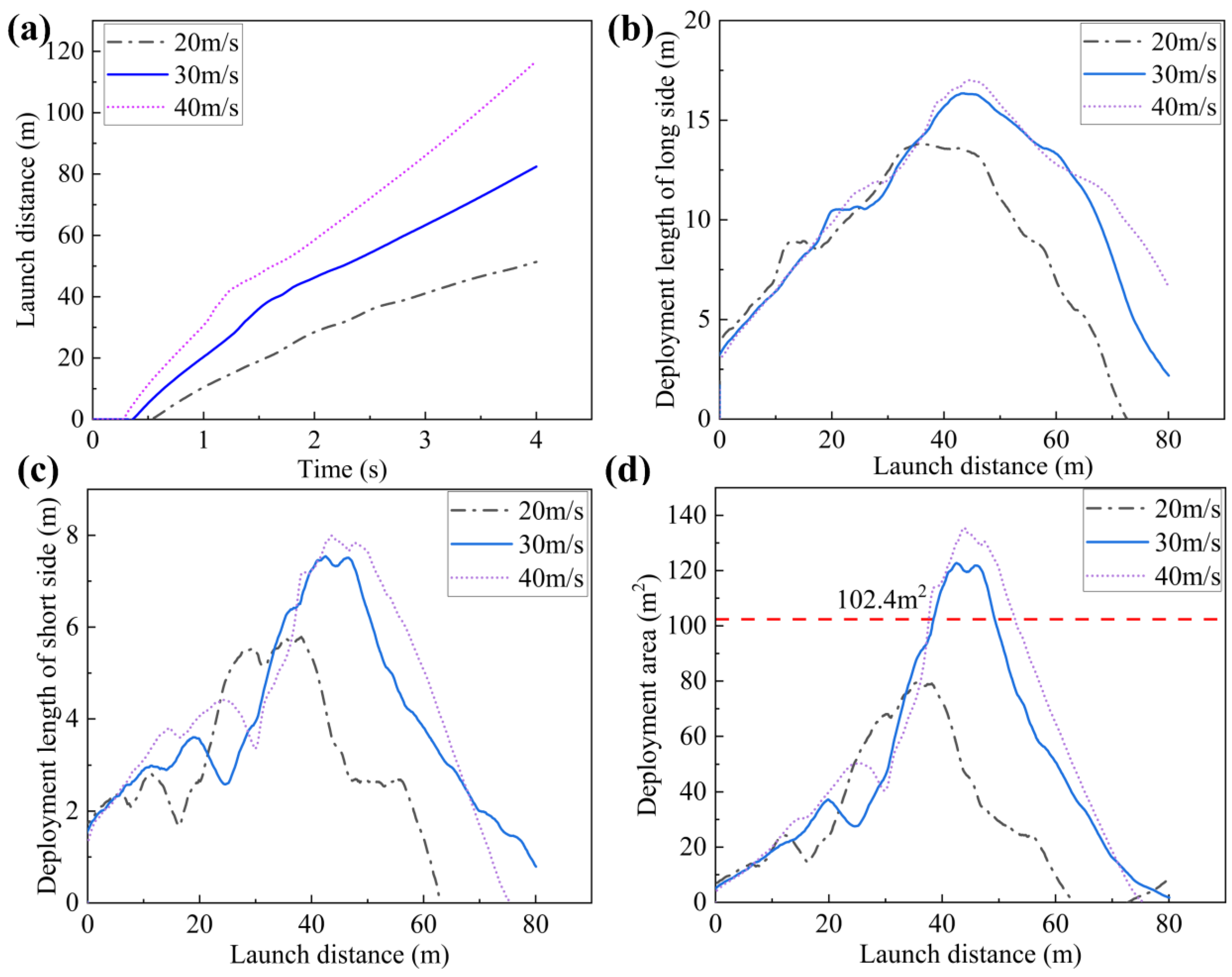
The launch speed of the towing blocks is another important parameter in tether-nets, as it has a vital impact on the deployment effect of tether-nets. In this section, the launch speed values of the towing blocks were set to 20 m/s, 30 m/s and 40 m/s, respectively, to study their influence on the dynamic responses of the tether-net. The results are shown in Figure 19 and Table 5.
As shown in Figure 19 and Table 5, with the increase in the launch speed from 20 m/s to 40 m/s, the maximum deployment area increased significantly, from 80 m2 to 135 m2. The maximum deployment lengths of the long and short sides increased from 13.8 m and 5.8 m to 17 m and 8 m, respectively. In addition, as shown in Figure 19 d, the range of the shape-preserving distance was reduced significantly with the decrease in launch speed. As the launch speed decreased from 40 m/s to 30 m/s, the range was reduced from 37.8~52.8 m to 38.5~48.9 m. When the launch speed was 20 m/s, the tether-net showed the lowest deployment area, with the maximum value not even reaching the area limit of 102.4 m2 throughout the whole deployment process. According to the above analysis, the deployment performance of the tether-net was better at the highest launch speed; however, the recoil impulse increased from 3.3 Ns to 6.5 Ns with the increase in launch speed from 20 m/s to 40 m/s based on Equation (22), which further caused an increase in structural weight.
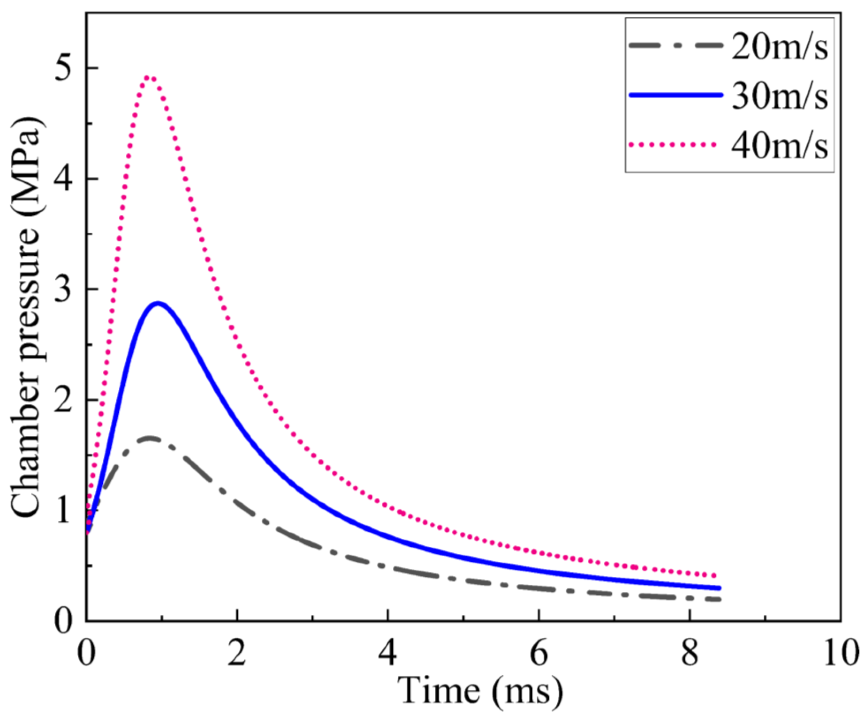
The influence of launch speed on chamber pressure was analyzed, and the results are shown in Figure 20. The results show that with the increase in launch speed from 20 m/s to 40 m/s, the maximum chamber pressure increased from 1.7 MPa to 4.9 MPa.

5. Conclusions

A new, rectangular tether-net deployed by towing blocks aiming to capture the main body of its target is proposed in this paper. Based on the explicit dynamic method, the dynamic model of the launch and deployment of the rectangular tether-net was established. Subsequently, on-ground experiments were designed and carried out. The accuracy of the established dynamic model was validated by comparing the real-time net configurations and launch distances of experiments and simulations. The effects of towing block mass and launch speed on tether-net deployment performance, including deployment length, deployment area and shape-preserving distance, were further studied. The conclusions can be drawn as follows:
(1) With the current design parameters, the maximum deployment area of the rectangular tether-net reached 122.3 m2, and the maximum expansion rate was 95.6%. The deployment distance was 42.8 m, and the shape-preserving distance ranged from 38.5 m to 48.9 m.
(2) Better deployment performance of the rectangular tether-net was obtained by increasing the towing block mass. However, the recoil force and impulse acting on the platform also increased, and the overall structural weight further increased. Additionally, the chamber pressure increased when the launch speed was maintained.
(3) Increasing the launch speed of the towing blocks also improved the deployment performance of the tether-net. However, higher recoil force, impulse acting on the platform and chamber pressure were induced by higher launch speed values, which affected the structural strength of the platform and rectangular tether-net system.

Author Contributions

Conceptualization, S.Y. and Z.D.; Software, M.L. and C.W.; Validation, M.L. and C.W.; Formal analysis, Z.Z.; Data curation, Z.Z.; Writing—original draft, S.Y.; Writing—review and editing, Q.Z.; Supervision, Z.D. All authors have read and agreed to the published version of the manuscript.

Funding

This work was supported by National Natural Science Foundation of China (No. 52102436); Fundamental Research Funds for the Central Universities (No. 30920021109); Natural Science Foundation of Jiangsu Province (No. BK20200496); China Postdoctoral Science Foundation (No. 2020M681615); and the project of Key Laboratory of Impact and Safety Engineering (Ningbo University), Ministry of Education (No. CJ202107).

Institutional Review Board Statement

Not applicable.

Informed Consent Statement

Not applicable.

Data Availability Statement

Data can be made available upon reasonable request.

Acknowledgments

All listed authors made significant scientific contributions to the research reported in the manuscript, approved its claims and agreed to be authors. Moreover, we also would like to thank Professor Du Zhonghua, who has provided us with valuable guidance in every stage of the writing of this thesis.

Conflicts of Interest

The authors declare that they have no conflicts of interest.

References

  1. Song, B.; Li, K.; Tang, H.-W. The latest development of foreign space debris. Int. Space 2021, 5, 14–19. [Google Scholar] [CrossRef]
  2. Mark, C.P.; Kamath, S. Review of Active Space Debris Removal Methods. Space Policy 2019, 47, 194–206. [Google Scholar] [CrossRef]
  3. Huang, P.F.; Zhang, F.; Cai, J.; Wang, D.K.; Meng, Z.J.; Guo, J. Dexterous Tethered Space Robot: Design, Measurement, Control and Experiment. IEEE Trans. Aerosp. Electron. Syst. 2017, 53, 1452–1468. [Google Scholar] [CrossRef]
  4. Cyril, X.; Jaar, G.J.; Misra, A.K. Dynamical modelling and control of a spacecraft-mounted manipulator capturing a spinning satellite. Acta Astronaut. 1995, 35, 167–174. [Google Scholar] [CrossRef]
  5. Golebiowski, W.; Michalczyka, R.; Dyrekb, M.; Battistac, U.; Wormnes, K. Validated simulator for space debris removal with nets and other flexible tethers applications. Acta Astronaut. 2016, 129, 229–240. [Google Scholar] [CrossRef]
  6. Yang, J.-K.; Ren, C.W.; Yang, C.H.; Wang, Y.Y.; Wan, S.-M.; Kang, R.J. Design of a Flexible Capture Mechanism Inspired by Sea Anemone for Non-cooperative Targets. Chin. J. Mech. Eng. 2021, 34, 77. [Google Scholar] [CrossRef]
  7. Sun, Y.J.; Wang, Q.; Liu, Y.-W.; Xie, Z.W.; Jin, M.H.; Liu, H. A survey of non-cooperative target capturing methods. J. Natl. Univ. Def. Technol. 2020, 42, 74–90. [Google Scholar] [CrossRef]
  8. Chen, T.; Wen, H. Autonomous assembly with collision avoidance of a fleet of flexible spacecraft based on disturbance observer. Acta Astronaut. 2018, 147, 86–96. [Google Scholar] [CrossRef]
  9. Gao, Q.Y.; Zhang, Q.B.; Peng, W.Y.; Tang, Q.G.; Feng, Z.W. Dynamic modelling and ground test of space nets. In Proceedings of the 2016 7th International Conference on Mechanical and Aerospace Engineering (ICMAE), London, UK, 18–20 July 2016; IEEE: London, UK, 2016; pp. 587–591. [Google Scholar] [CrossRef]
  10. Shan, M.H.; Guo, J.; Gill, E. Deployment Dynamics of Tethered-Net for Space Debris Removal. Acta Astronaut. 2017, 132, 293–302. [Google Scholar] [CrossRef]
  11. Botta, E.M.; Sharf, I.; Misra, A.K. Contact dynamics modeling and simulation of tether nets for space-debris capture. J. Guid. Control Dyn. 2017, 40, 110–123. [Google Scholar] [CrossRef]
  12. Bridson, R.; Fedkiw, R.; Anderson, J. Robust treatment of collisions, contact and friction for cloth animation. ACM Trans. Graph. 2002, 21, 594–603. [Google Scholar] [CrossRef]
  13. Harmon, D.; Vouga, E.; Tamstorf, R.; Grinspun, E. Robust treatment of simultaneous collisions. In ACM SIGGRAPH 2008 Papers, Proceedings of the Special Interest Group on Computer Graphics and Interactive Techniques Conference, Los Angeles, CA, USA, 11–15 August 2008; Association for Computing Machinery: New York, NY, USA, 2008; pp. 1–4. [Google Scholar] [CrossRef] [Green Version]
  14. Si, J.Y.; Pang, Z.J.; Du, Z.H.; Cheng, C. Dynamic modeling and simulation of self-collision of tether-net for space debris removal. Adv. Space Res. 2019, 64, 1675–1687. [Google Scholar] [CrossRef]
  15. Yu, Y.; Baoyin, H.X.; Li, J.F. Dynamic modeling and Simulation of space flying net projectile deployment. J. Astronaut. 2010, 31, 1289–1296. [Google Scholar] [CrossRef]
  16. Botta, E.M.; Sharf, I.; Misra, A.K.; Teichmann, M. On the simulation of tether-nets for space debris capture with vortex dynamics. Acta Astronaut. 2016, 123, 91–102. [Google Scholar] [CrossRef]
  17. Botta, E.M.; Sharf, I.; Misra, A.K. Energy and Momentum Analysis of the Deployment Dynamics of Nets in Space. Acta Astronaut. 2017, 140, 554–564. [Google Scholar] [CrossRef]
  18. Li, J.Y.; Yu, Y.; Baoyin, H.X.; Li, J.F. Comparative study on two dynamic models of space flying net. Chin. J. Theor. Appl. Mech. 2011, 43, 542–550. [Google Scholar] [CrossRef]
  19. Zhang, F.; Huang, P.F. Releasing Dynamics and Stability Control of Maneuverable Tethered Space Net. IEEE/ASME Trans. Mechatron. 2017, 22, 983–993. [Google Scholar] [CrossRef]
  20. Benvenuto, R.; Lavagna, M.; Salvi, S. Multibody dynamics driving GNC and system design in tethered nets for active debris removal. Adv. Space Res. 2016, 58, 45–63. [Google Scholar] [CrossRef]
  21. Sharf, I.; Thomsen, B.; Botta, E.M.; Misra, A.K. Experiments and simulation of a net closing mechanism for tether-net capture of space debris. Acta Astronaut. 2017, 139, 332–343. [Google Scholar] [CrossRef]
  22. Yu, Y.; Baoyin, H.X.; Li, J.F. Dynamic modeling method of space tether-net system. In Proceedings of the 16th Annual Meeting of Beijing Society of Mechanics; Beijing Society of Theoretical and Applied Mechanics: Beijing, China, 2010; pp. 164–166. [Google Scholar]
  23. Liu, H.T.; Zhang, Q.B.; Yang, L.P.; Zhu, Y.W. The deployment dynamic characteristics analysis of space web system. J. Natl. Univ. Def. Technol. 2015, 37, 68–77. [Google Scholar] [CrossRef]
  24. Wang, X.C.; Shao, M. Basic Principle and Numerical Method of Finite Element Method; Tsinghua Press: Beijing, China, 1997. [Google Scholar]
  25. Zhuang, Z.; You, X.C.; Liao, J.H. Based on ABAQUS Finite Element Analysis and Application; Tsinghua Press: Beijing, China, 2009. [Google Scholar]
  26. Wang, Y.L.; Yu, Y.; Wang, C.Y.; Zhou, G.; Aminreza, K.; Zhao, W.Z. On the out-of-plane ballistic performances of hexagonal, reentrant, square, triangular and circular honeycomb panels. Int. J. Mech. Sci. 2020, 173, 105402. [Google Scholar] [CrossRef]
  27. Yue, S.; Titurus, B.; Nie, H.; Zhang, M. Liquid spring damper for vertical landing Reusable Launch Vehicle under impact conditions. Mech. Syst. Signal Process. 2019, 121, 579–599. [Google Scholar] [CrossRef] [Green Version]
Figure 1. Capture process of rectangular tether-net, (a) t = 1 s, (b) t = 2 s, (c) t = 3 s, (d) t = 4 s.
Aerospace 10 00115 g001
Figure 2. Main structure of rectangular tether-net system. (a) Cutaway view. (b) Top view.
Aerospace 10 00115 g002
Figure 3. Schematic diagram of launching angle setting.
Aerospace 10 00115 g003
Figure 4. Configuration of rectangular tether-net.
Aerospace 10 00115 g004
Figure 5. Stress of the truss element.
Aerospace 10 00115 g005
Figure 6. Contact pair between net tethers.
Aerospace 10 00115 g006
Figure 7. Results of tensile stiffness test of net tethers.
Aerospace 10 00115 g007
Figure 8. Flowchart of procedure to determine tether stiffness.
Aerospace 10 00115 g008
Figure 9. Tether segment tension during deployment.
Aerospace 10 00115 g009
Figure 10. Result of stiffness selection.
Aerospace 10 00115 g010
Figure 11. On-ground experiment. (a) Experimental setup. (b) Launcher of tether-net.
Aerospace 10 00115 g011
Figure 12. Comparison of tether-net configuration between simulations and experiments. (a) On-site photos of on-ground experiments. (b) Main view of simulation results. (c) Top view of simulation results.
Aerospace 10 00115 g012
Figure 13. Comparison of launch distance between simulations and experiments.
Aerospace 10 00115 g013
Figure 14. Configuration of tether-net during deployment with initial parameters. (a) Main view. (b) Top view.
Aerospace 10 00115 g014
Figure 15. Tether-net deployment performance. (a) Launch distance. (b) Deployment length of long side. (c) Deployment length of short side. (d) Deployment area.
Aerospace 10 00115 g015
Figure 16. Displacement of different towing blocks. (a) Displacement–launch distance. (b) Displacement–time.
Aerospace 10 00115 g016
Figure 17. Deployment performance with different towing block mass values. (a) Launch distance. (b) Deployment length of long side. (c) Deployment length of short side. (d) Deployment area.
Aerospace 10 00115 g017
Figure 18. Chamber pressure with different towing block mass values.
Aerospace 10 00115 g018
Figure 19. Deployment performance with different launch speed values. (a) Launch distance. (b) Deployment length of long side. (c) Deployment length of short side. (d) Deployment area.
Aerospace 10 00115 g019
Figure 20. Chamber pressure with different launch speed values.
Aerospace 10 00115 g020
Table 1. Initial parameters of the dynamic model.
ParameterValue
Net size, m216 × 8
Net mesh, m20.8 × 0.8
Diameter of main tethers, mm0.5
Diameter of side tethers, mm2
Diameter of towing tethers, mm2
Towing block mass, g170
Launch speed, m/s30
Launch angle, °16
Table 2. Summary of elastic moduli of net tethers.
Tether Type Elastic Modulus
Main tether748.7 MPa
Towing tether59.5 MPa
Side tether46.2 MPa
Table 3. Deployment parameters.
ParameterValue
Maximum deployment length of the long side, m16.3
Maximum deployment length of the short side, m7.5
Maximum deployment area, m2122.3
Deployment distance, m42.8
Shape-preserving distance, m~m38.5~48.9
Table 4. Deployment parameters with different towing block mass.
Parameter150 g170 g190 g
Maximum deployment length of the long side, m1616.316.6
Maximum deployment length of the short side, m7.27.57.8
Maximum deployment area, m2114.3122.3128.7
Deployment distance, m42.842.845
Shape-preserving distance, m~m39.3~48.238.5~48.938.7~48.9
Table 5. Deployment parameters with different launch speeds.
Parameter20 m/s30 m/s40 m/s
Maximum deployment length of the long side, m13.816.317
Maximum deployment length of the short side, m5.87.58
Maximum deployment area, m280122.3135
Deployment distance, m42.842.845
Shape-preserving distance, m~m 38.5~48.937.8~52.8
Disclaimer/Publisher’s Note: The statements, opinions and data contained in all publications are solely those of the individual author(s) and contributor(s) and not of MDPI and/or the editor(s). MDPI and/or the editor(s) disclaim responsibility for any injury to people or property resulting from any ideas, methods, instructions or products referred to in the content.