Abstract
The variable cycle engine selects the appropriate working mode through mode switch to meet the requirements of low specific fuel consumption and high unit thrust. When the variable cycle engine switches between different modes, it should ensure the smooth transition of working modes and obtain the expected performance at the same time. Consequently, a general control schedule design method for mode switch is investigated in this paper. The feasible switching domains of single-bypass working mode and double-bypass working modes are obtained based on multifurcating tree traversal, and the switching point in the feasible switching domain is determined by solving the collaboration-game optimization problem based on sequential quadratic programming (SQP). Finally, the schedule of control variables is designed to realize smooth and fast switching between different working modes of variable cycle engine. The simulations show that based on the general control schedule of mode switch proposed in this paper, smooth transition of thrust and rotor speed can be achieved under the premise of safe engine operation, with small fluctuations and a short switching time, which is about 2.5 s.
1. Introduction
Due to its unique geometric structure, the variable cycle engine has the advantages of high specific thrust (produced by a low-bypass ratio turbofan engine) and low specific fuel consumption (by a high-bypass ratio turbofan engine), leading to it becoming one of the research hotspots in various countries [1,2]. Different structures of variable cycle engines have been designed by various aviation-focused countries, which are only theoretical studies and have not been put into production [3,4]. The third-generation variable cycle engine YF120 of the United States is the world’s first flight-proven variable cycle engine [5,6]. Compared with the traditional aeroengine, the most remarkable feature of the variable cycle engine is that there is more than one working mode. As far as the double-bypass variable cycle engine is concerned, there are two working modes: single-bypass working mode and double-bypass working mode [7,8,9]. Smooth and fast switching between modes is an important prerequisite for the variable cycle engine to achieve its expected performance [10,11].
There has been plenty of research on the mode switching of variable cycle engines. In the early 1980s, GE, in the United States, completed research on the variable geometry components and control system of a double-bypass variable cycle engine, and carried out the mode transition test of the ground demonstrator. However, only some of the control laws and test data of the mode transition process are in the open literature, and the design method of the control law of the mode transition process is not available [12,13,14,15]. Xu et al. adopted the decoupled method to calculate the performance of the front-variable-area bypass injector with high accuracy, which provides a basis for the design of a control schedule for mode switching of a variable cycle engine [16]. Xu et al. set reasonable design parameters for the core-driven fan stage to further improve the matching degree among components and the overall performance of the variable cycle engine model, thereby providing the possibility for the subsequent comprehensive and better control schedule design [17]. In addition, many scholars have also studied from the perspective of variable cycle engine modeling to lay the foundation for control schedule design [18,19].
Hao et al. mainly pointed out that the mode switch point should be determined comprehensively from the bypass ratio and specific fuel consumption, but did not give the change process of the geometric components of the mode switch in detail [20]. Chen et al. developed the adjustment sequence of each geometric component in the mode switch process from the perspectives of aeroengine safety and stability [21]. LV et al. investigated the effect of variable geometry in a rotating guide vane on the performance of an aeroengine and used it as a basis to try to come up with a feasible control schedule for mode switching [22].
All of these studies were based on the analysis of component characteristics to manually try to develop a control schedule for mode switching, which is not universal and is not conducive to the stable and efficient operation of the aeroengine within the whole flight envelope [23,24]. Zhang et al. studied the general control schedule for mode switching based on particle swarm optimization algorithm to avoid a manual trial but ignored the timing of mode switch of variable cycle engine [25].
A variable cycle engine is mission-oriented and achieves a more suitable working mode through mode switch, so as to obtain lower specific fuel consumption or higher unit thrust [26,27]. Gronstedt et al. determined the starting point and the ending point of mode switch mainly according to the specific fuel consumption, but the simulation showed that the thrust fluctuation was too large, and the engine operation stability was not considered in their research [28]. Ulizar et al. determined the mode switching point according to the requirements of the engine flight mission, but the constraints were not considered in the process, which was not conducive to the safe operation of the aeroengine [29].
Therefore, a general control schedule design method for mode switch of the variable cycle engine is proposed in this paper, which considers switching time, switching smoothness and constraints. The timing of mode switch is explored under the premise of no surge, no over-rotation and no over-temperature, and the feasible switching domain of mode switch is determined based on multifurcating tree traversal. The collaboration-game optimization problem is constructed considering the factors of thrust fluctuation, flow fluctuation and engine operation safety, and SQP is used to solve the optimization problem to determine the critical points of mode switch in the feasible switching domain. Based on the optimization results, the schedule of control variables during mode switch is designed to achieve smooth and fast mode switch.
It can be seen in the above that the conventional design methods for a mode switch control schedule only manually try to work out a feasible control schedule at typical operating points and do not fully consider the engine’s operation restrictions and actual operating state. In contrast, the proposed method is universal and applicable to the whole flight envelope of variable cycle engine. The safety and stability of the engine during operation are fully considered.
The remainder of the paper is organized as follows. Section 2 briefly introduces the requirements and steps of determining feasible switching domain of control variables; Section 3 focuses on the construction and solution of the collaboration-game optimization problem, so as to determine the starting point and ending point of mode switch; Section 4 designs the schedule of control variables based on the previous section; in Section 5, simulation and analysis are reported to verify the feasibility and effectiveness of the proposed method; Section 6 presents a summary.
2. Selection of Feasible Domain of Control Variables for Mode Switch
Mode switch is a remarkable feature of variable cycle engines, which are different from traditional aeroengine. By adjusting geometric components, the variable cycle engine can smoothly switch modes so that it can still maintain a high inlet flow rate when meeting different thrust requirements and achieve lower specific fuel consumption and less spillage drag than the conventional turbofan. The relevant research was carried out based on the component-level model of the variable cycle engine shown in Figure 1. The numbers in the figure represent each cross section of the variable cycle engine. The number 2 represents the fan inlet, the number 21 represents the fan outlet, the number 23 represents the CDFS (core driven fan stage) inlet, the number 24 represents the CDFS outlet, the number 15 represents the first bypass, the number 3 represents the HPC (high-pressure compressor) outlet, the number 4 represents the combustion chamber outlet, the number 5 represents the LPT (low pressure turbine) outlet, the number 6 represents the internal duct outlet, the number 7 represents the nozzle inlet, the number 8 represents the nozzle throat, the number 9 represents the nozzle outlet, the number 114 represents the MSV (mode selection valve), the number 224 represents the FVABI (front-variable-area bypass injector), the number 163 represents the RVABI (rear-variable-area bypass injector). The variable cycle engine mainly includes an inlet, a fan, a CDFS, an HPC, a combustion chamber, an HPT (high-pressure turbine), an LPT, a bypass, a mixer and a nozzle. The variable geometry components are an MSV, an FVABI, an RVABI, a CDFS with a guide vane, an HPC with a guide vane and an LPT with a guide vane.
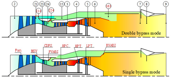
Figure 1.
Structure diagram of a variable cycle engine.
The mode switch is mission-oriented—that is, mode switch is performed only when the current working mode cannot meet the mission requirements, so the occurrence of mode switch needs to meet certain conditions. In this paper, the concept of feasible domain of control variables for mode switch is put forward. The aeroengine can switch modes only when it reaches the feasible domain of control variables from any state, as shown in Figure 2.
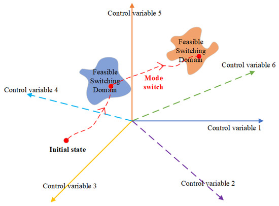
Figure 2.
Mode switching process.
Figure 2 shows that the start and end of mode switch both need to reach the feasible switching domain. At the same operating point, the feasible switching domain for mode switch is fixed, no matter whether the variable cycle engine switches from the double bypass to the single bypass mode or the variable cycle engine switches from the single bypass mode to the double bypass mode. Therefore, the variable cycle engine switching from the double bypass to the single bypass mode at the ground design point is analyzed as an example. When the variable cycle engine switches from double bypass mode to single bypass mode, the flow rate should be the maximum flow rate that can be achieved by the variable cycle engine with double bypass mode; that is, the low-pressure speed should be close to 100%, and the thrust should also be the maximum thrust at the ground design point without afterburning. At the same time, the bypass ratio is less than that at the design point, and the specific fuel consumption is greater than that at the design point; that is, the variable cycle engine has no advantage in continuing to work in double bypass mode, so it needs to switch to single bypass mode to continue to complete the flight mission [20]. Additionally, the whole process of mode switch needs to ensure a certain surge margin [25]. To sum up, the feasible switching domain requirements of variable cycle engine in double bypass mode are shown in Condition (1). The specific values of the limits in the condition are mainly based on engineering experience, and the rotor speed and thrust in this condition were normalized according to the design value.
where N is the rotor speed; F is the thrust; B is the bypass ratio; SFC is the specific fuel consumption; SM is the surge margin of different variable geometry compression components, that is, the fan, the CDFS and the HPC. Subscript L represents the low-pressure shaft, and the subscript d represents the ground design point. Meanwhile, the feasible switching domain requirements of variable cycle engine in single bypass mode are shown in Condition (2).
In this paper, the adjustable control variables of the variable cycle engine are shown in Table 1. It is necessary to find a suitable combination of control variables so that the performance of the engine meets the requirements of Condition (1) and Condition (2). The control variable flag, the control variable A114, and the control variable A224 have the fixed values in double bypass mode and in single bypass mode during mode switch, as shown in Table 2, which is not included in the control variables to be adjusted.

Table 1.
Adjustable control variables of a variable cycle engine.
Table 2.
Control variables with fixed values in double bypass mode and in single bypass mode.
Each adjustable control variable has a range of values, and the parameters’ values are selected to be at equal intervals. Multifurcating tree traversal is used to find the combinations of control variables that meet the requirements of switching to a feasible domain, as shown in Figure 3. Take a certain fuel flow rate as an example, this fuel flow rate corresponds to multiple A8, and each A8 also corresponds to multiple A163, and so on. Each path to the leaf node is a combination of control variables. Thus, several groups of feasible switching points which meet the switching requirements are determined.
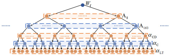
Figure 3.
Structure diagram of multifurcating tree traversal.
Considering that the control variables of aeroengine change continuously, the control variables under the action of control variables also change continuously, so the determined feasible switching points based on multifurcating tree traversal can be extended to the feasible switching domain, that is, multidimensional subspace. The feasible switching domain of the starting point of mode switch is defined as , and the feasible switching domain of the ending point of mode switch is defined as . The schedule diagram of the feasible switching domains of control variables is shown in Figure 4. In the figure, each line in the black box on the right is a combination of control variables found by multifurcating tree traversal that meets the switching requirements, namely, a point in or in the black box on the left. Multiple points can constitute a convex domain, which is the feasible switching domain.
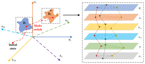
Figure 4.
Schematic diagram of feasible switching domains of control variables.
3. Determination of the Critical Points of Mode Switch
After the feasible switching domain consisting of the combination of each control variable is determined, the starting and ending points of mode switch need to be further determined. The initial state of the engine is random; it is actually an optimization problem to determine the critical point of mode switch in the feasible switching domain based on the control cost and the requirements of mode switch. Therefore, in this section, the collaboration-game optimization problem is further constructed and solved. Compared with the quadratic objective function based on empirical coefficients, the optimization problem constructed by game theory can be proved to have Pareto optimal solution by the following content.
3.1. Preliminaries of Cooperative Game Theory
The three main elements of the game are, respectively, the players, the feasible decisions of the players and the cost function associated with the decisions of all the players for each player. Consider a game problem with N players, and according to the game rules, the mapping relationship is as follows.
where Di and are the decision set and cost function of the player i, respectively. is the field of real numbers. This formula shows that the cost function of each player is affected by the decisions of other players. Usually, each player expects the least cost, so there exits the ideal decision that for all players satisfies
This means that it is necessary to obtain an N-tuple decision to minimize the cost function of each player. However, in general, there is no such perfect result [30,31,32]. In this way, players are faced with the choice of which mentality to use in the game. If each player works together to minimize the cost of all players, this kind of game is a collaboration game, and if each player only wants to minimize its own cost but does not care about the cost of other players, this kind of game is a non-collaboration game. The optimization problem constructed in this paper achieves the optimal matching between control cost and system performance through the common allocation of parameters. In this sense, this paper explores the problem of parameter optimization based on a kind of collaboration game.
The N-tuple decision or the joint decision is said to be Pareto-optimal if and only if the choice of other joint decisions leads to an increase in the cost of at least one participant, since this violates the collaborative mindset of the participants. That is, a decision N-tuple is Pareto optimal if and only if for each , it satisfies
or there exists at least one participant which satisfies
A graphic description about Pareto optimality is shown in Figure 5. Three players (the blue one, the orange one and the yellow one) pull a rigid plate at the same time, and the distances they pull represent the cost of the player. The farther the distance, the higher the cost. From (a), all players are at Pareto optimality; the plate is in the balance situation. When one player moves away from Pareto optimality, the plate is tilted. The cost of the blue player in (b) or the cost of the yellow player in (c) is increased without considering other players.
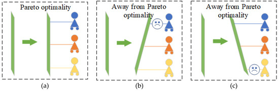
Figure 5.
Pareto optimality, (a) an example of Pareto optimality; (b) an example of deviating from Pareto optimality; (c) another example of deviating from Pareto optimality.
Then a lemma that contains sufficiency conditions for Pareto optimality can be established.
Lemma 1.
If there exist,and, satisfying
where, the N-tuple setis Pareto optimal [33].
From the above description, it can be seen that by treating the control variables and the objective function as decision and cost, the problem of determining critical points of mode switch studied in this paper can be transformed into the problem of seeking the optimal solution of the collaboration game.
3.2. Construction and Solution of Optimization Problems
In order to find the optimal combination of control variables, this section regards each control variable as a participant and constructs the cost function of each participant based on the requirements of mode switch.
The requirements for mode switch of variable cycle engine are as follows:
- Under the premise of reliable operation (no over-temperature, no surge and no over-rotation), the switching time should be as short as possible.
- All performance parameters, such as thrust, change smoothly (no sudden changes).
- The flow fluctuation is small; that is, the low-pressure rotor speed fluctuation is small.
Since the players in the collaboration game focus on the joint benefit, the performance cost and the control cost can be randomly allocated to each player. Participants in this collaboration game problem are , , , , and , as shown in Figure 6.
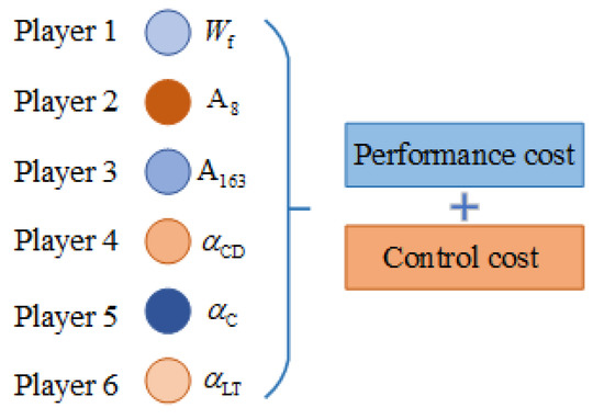
Figure 6.
Schematic diagram of the collaboration game.
Aiming at determining the starting point of mode switch from any initial state of the aeroengine, the following cost function was designed.
where represents the control variables of the starting point of mode switch, represents the control variables of the any initial state of aeroengine, represents the increment in control variables, represents the low-pressure rotor speed of the starting point and represents the low-pressure rotor speed of the ground design point. The cost function for the first player includes the control cost of itself and the performance cost which represents the best performance of the current working mode. The cost functions for other players are the control costs of themselves. There is a coupling relationship between the cost functions of all players, which embodies the concept of a cooperative game.
Recall from the definition of Pareto optimality that if there exist , and such that
the is Pareto-optimal, where .
Then, the problem of finding the Pareto optimality can be transformed to the following problem of constrained optimization, for any given , subject to
and the following restrictions need to be met.
Similarly, for determining the ending point of mode switch from the starting point of mode switch, the following cost function was designed:
where represents the control variables of the ending point of mode switch, represents the increment of control variables, represents the low-pressure rotor speed of the ending point, represents the thrust of the ending point of mode switch and represents the thrust of the starting point of mode switch. The second term on the right of the first equation is to reduce the rotor speed fluctuation during mode switch, and the third term is to reduce the thrust fluctuation during mode switch.
If there exist , and such that
the is a Pareto-optimal, where .
Then, the problem of finding the Pareto optimality can also be transformed to the following problem of constrained optimization, for any given , subject to
and the following restrictions need to be met.
So far, two collaboration-game optimization problems with constraints have been established for mode switch. In this paper, SQP is used to solve the optimization problem, and the optimal combination of control variables corresponding to the starting and ending points of mode switch is determined.
4. Design for Change Law of Control Variables
The optimal combination of control variables corresponding to the starting point and the ending point of mode switch is determined by solving the collaboration-game optimization problem in the previous section. From any initial state to the starting point of the mode switch, the control variables are designed to incrementally ramp up to the value corresponding to the starting point with the maximum increment of control variables limited by the actuator. In the process of mode switch, each control variable is designed to change from the value at the starting point of mode switch to the value at the end point of mode switch in a ramping fashion, and the switching time is set to 2.5 s, that is, the change in each control variable is to be completed within 2.5 s, as shown in Figure 7.
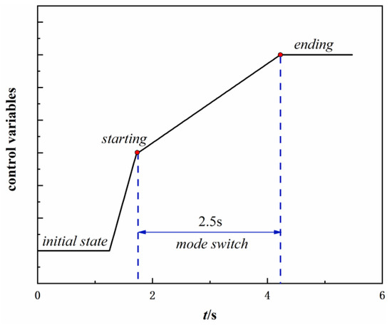
Figure 7.
Change curves of optimized control variables.
The change curves of control variables with fixed values in single bypass mode and double bypass mode, shown in Table 2, are shown in Figure 8 and Figure 9, which are designed to ramp-up or ramp-down. All control variables are set to change at the same time.
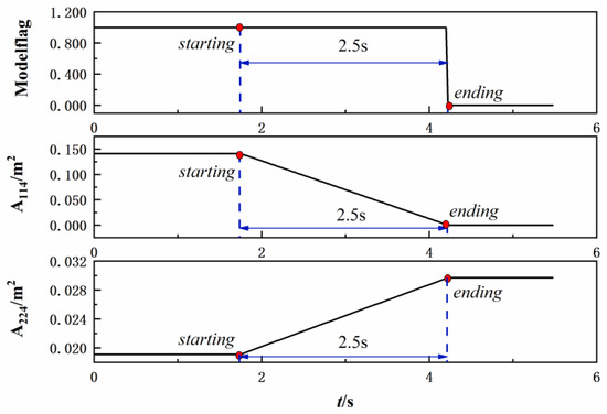
Figure 8.
Schedule of control variables with fixed values switching from double bypass to single bypass mode.
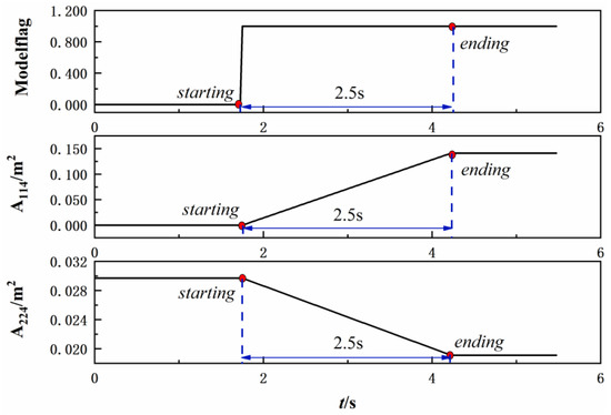
Figure 9.
Schedule of control variables with fixed values switching from single bypass to double bypass mode.
5. Simulation and Analysis
In one flight cycle of an aircraft, the appropriate variable cycle engine working mode should be selected for different flight states, which include idling, take off, climb, subsonic cruise, supersonic cruise, landing and approaching idling, as shown in Figure 10. The orange block represents the double bypass mode, and the blue block represents the single bypass mode. The red arrow indicates that the variable cycle engine needs to switch working modes.
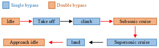
Figure 10.
Schematic diagram of the flight cycle of an aircraft.
As can be seen in the figure, the variable cycle engine is in the double bypass mode when it is in the idle state, and the operation mode is switched from the double bypass mode to the single bypass mode when the aeroengine needs to maintain high thrust during taking off and climbing. For subsonic cruising, the operating mode is switched to double bypass mode to achieve lower specific fuel consumption. In supersonic cruising, the single bypass mode is used to obtain more thrust, and the aeroengine should be switched to double bypass mode again when approaching idling.
Considering the applicable situation of the operating mode in the flight cycle, the simulation verification of the general control schedule design method for mode switch was carried out for two state points. One was the ground design point, altitude H = 0 km, Mach = 0, because at this point, the engine needs to switch between single bypass and double bypass mode to obtain lower specific fuel consumption or higher thrust. The other was the point of altitude H = 11 km, Mach = 1.2, considering that the double bypass mode of the variable cycle engine can realize a supersonic cruise at low Mach; it is a design feature for the engine to switch modes at Mach = 1.2.
5.1. Simulation of Mode Switch at the Design Point
Firstly, the simulation verification of switching from double bypass mode to single bypass mode was carried out. According to a randomly given initial state of the aeroengine, the optimal control variables of the starting point and the ending point of mode switch can be obtained based on the research in the previous section. Based on the control law designed in Section 4, the change curves of thrust, low pressure rotor speed and surge margin during mode switch are shown in Figure 11, Figure 12 and Figure 13. The thrust and low-pressure rotation speed in the figures were normalized. The fluctuation of the parameter is as follows:
where represents the value of the parameter of the starting point and represents the maximum value of fluctuation.

Figure 11.
Change curve of thrust of working-mode switching from double bypass to single bypass at H = 0 km, Ma = 0.
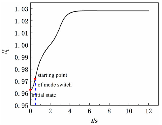
Figure 12.
Change curve of low-pressure rotor speed of working-mode switching from double bypass to single bypass at H = 0 km, Ma = 0.
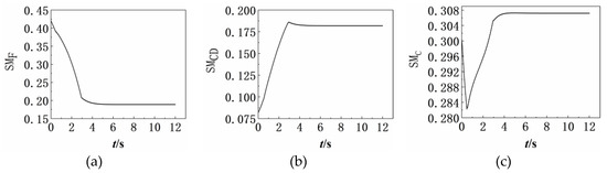
Figure 13.
Change curves of surge margin of working-mode switching from double bypass to single bypass at H = 0 km, Ma = 0, (a) Surge margin of fan; (b) surge margin of CDFS; (c) surge margin of HPC.
As can be seen in the above figure, when the variable cycle engine is switched from the double-bypass working mode to the single-bypass working mode at the design point, there is almost no fluctuation in thrust or speed, and a surge margin of more than 8% is ensured. The switching time is 2.5 s, and the time for the engine state to stabilize is about 4 s (the time for the engine state to stabilize refers to the time required for the response to reach and stay within of the final value). Therefore, the design method of the general control schedule for mode switch proposed in this paper is effective and feasible.
Similarly, the simulation verification of switching from single bypass mode to double bypass mode is also carried out. Based on the same control schedule design steps, the results are shown in Figure 14, Figure 15 and Figure 16.
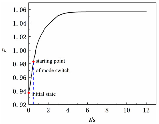
Figure 14.
Change curve of thrust of working-mode switching from single bypass to double bypass at H = 0 km, Ma = 0.
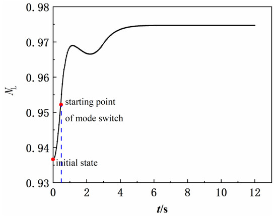
Figure 15.
Change curve of low-pressure rotor speed of working-mode switching from single bypass to double bypass at H = 0 km, Ma = 0.
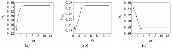
Figure 16.
Change curves of surge margin of working-mode switching from single bypass to double bypass at H = 0 km, Ma = 0. (a) Surge margin of fan; (b) surge margin of CDFS; (c) surge margin of HPC.
It can be seen in the above figure that when the variable cycle engine is switched from the single-bypass working mode to the double-bypass working mode at the design point, there is almost no fluctuation in thrust or rotation speed, and a surge margin of more than 10% is ensured. The switching time is 2.5 s, and the time for the engine state to stabilize is less than 4 s, which verifies the effectiveness and feasibility of the proposed control schedule design method.
5.2. Simulation of Mode Switch at the High-Altitude Point
In addition to the simulation verification at the ground design point, the relevant simulation was also carried out at the high-altitude point, namely, H = 11 km, Mach = 1.2. Based on the control schedule design method in the previous section, the change law of control variables of the variable cycle engine switching from double-bypass working mode to single-bypass working mode was designed at this state point, and the simulation results are shown in Figure 17, Figure 18 and Figure 19.

Figure 17.
Change curve of thrust of working-mode switching from double bypass to single bypass at H = 11 km, Ma = 1.2.
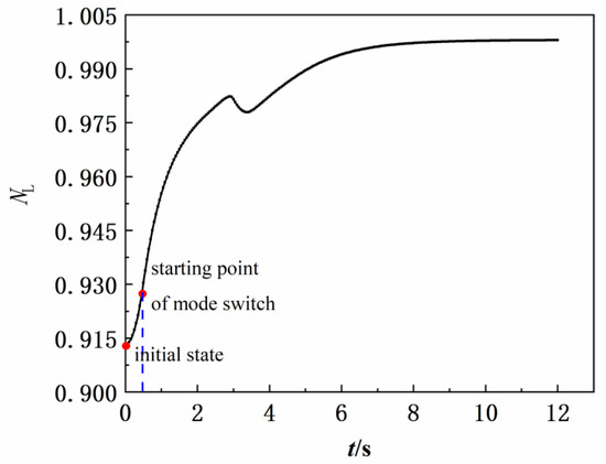
Figure 18.
Change curve of low-pressure rotor speed of working-mode switching from double bypass to single bypass at H = 11 km, Ma = 1.2.
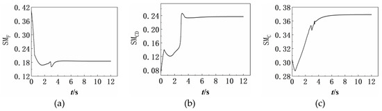
Figure 19.
Change curves of the surge margin of working-mode switching from double bypass to single bypass at H = 11 km, Ma = 1.2. (a) surge margin of fan; (b) surge margin of CDFS; (c) surge margin of HPC.
As can be seen in the above figure, when the variable cycle engine is switched from the double-bypass working mode to the single-bypass working mode at the high-altitude point, there is almost no fluctuation in thrust or rotation speed according to Equation (18), and a surge margin of more than 8% is ensured. The switching time is 2.5 s, and the time for the engine state to stabilize is about 6.5 s. Thus, the proposed control schedule design method for mode switch is also applicable to the off-design point of the variable cycle engine.
At the high-altitude point, the simulation results of variable cycle engine switching from single bypass mode to double bypass mode are as follows (Figure 20, Figure 21 and Figure 22).
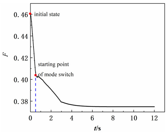
Figure 20.
Change curve of thrust of working-mode switching from single bypass to double bypass at H = 11 km, Ma = 1.2.
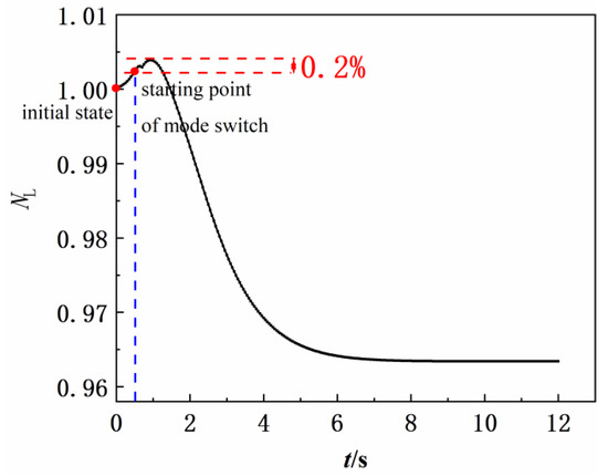
Figure 21.
Change curve of low-pressure rotor speed of working-mode switching from single bypass to double bypass at H = 11 km, Ma = 1.2.
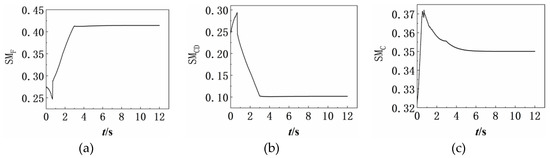
Figure 22.
Change curves of the surge margin of working-mode switching from single bypass to double bypass at H = 11 km, Ma = 1.2. (a) Surge margin of fan; (b) surge margin of CDFS; (c) surge margin of HPC.
It can be seen in the above figure that when the variable cycle engine is switched from the single-bypass working mode to the double-bypass working mode at the high-altitude point, there is almost no fluctuation in thrust, the fluctuation of rotation speed is about 0.2% and a surge margin of more than 10% is ensured. The switching time is 2.5 s, and the time for the engine state to stabilize is less than 4.7 s.
So far, the control schedule design method for mode switch proposed in this paper has been verified at typical points, namely, on the ground point and at a high altitude. In the mode switch process, the parameter fluctuation is small, the switching time is short and there is no surge, so smooth and fast switching can be achieved.
6. Conclusions
A general control schedule design method based on game theory for mode switch of a variable cycle engine was proposed in this paper. The following conclusions can be drawn:
- Based on the multifurcating tree traversal, a feasible switching domain that meets the requirements of mode switch and the limits of the aeroengine is obtained, which fundamentally ensures the safe and stable operation of the aeroengine during mode switch, and the timing of mode switch was investigated from the perspective of flight mission requirements.
- Considering the fluctuation requirements of mode switch and the limitations of aeroengines, the collaboration-game optimization problem was established and solved based on SQP. Based on any initial state, the optimal starting and ending points of mode switching can be determined by solving the cooperative game optimization problem.
- The open-loop change law of control variables was given, which is simple and effective, and it is easy to design the control schedule for mode switch of each state in time during the operation of aeroengine.
- According to the simulation results of mode switch of the variable cycle engine on the ground and at a high altitude, the general control schedule design method for mode switch in this paper can realize smooth, fast and safe mode switching, and has feasibility and effectiveness for the whole flight envelope.
Author Contributions
Conceptualization, J.H. and M.P.; methodology, Y.W.; software, Y.W.; validation, J.H., M.P. and W.Z.; formal analysis, Y.W.; investigation, M.P. and W.Z.; resources, J.H.; data curation, Y.W.; writing—original draft preparation, Y.W.; writing—review and editing, J.H. and M.P.; visualization, M.P.; supervision, J.H.; project administration, J.H.; funding acquisition, J.H. and M.P. All authors have read and agreed to the published version of the manuscript.
Funding
This research was funded by the National Science and Technology Major Project (No. 2019-V-0003-0094).
Data Availability Statement
Data are contained within the article.
Acknowledgments
The authors gratefully acknowledge the financial support for this project from the National Science and Technology Major Project (No. 2019-V-0003-0094).
Conflicts of Interest
The authors declare that they have no known competing financial interest or personal relationship that could have appeared to influence the work reported in this paper.
References
- Berton, J.J.; Haller, W.J.; Seidel, J.A.; Senick, P.F. A NASA Lewis comparative propulsion system assessment for the High-Speed Civil Transport. NASA 19940028971; 1992. Available online: https://ntrs.nasa.gov/citations/19940028971 (accessed on 20 November 2022).
- Vyvey, P.; Bosschaerts, W.; Fernandez, V.; Paniagua, G. Study of an Airbreathing Variable Cycle Engine. In Proceedings of the 47th AIAA/ASME/SAE/ASEE Joint Propulsion Conference & Exhibit, San Diego, CA, USA, 31 July 2011–3 August 2011. [Google Scholar]
- Wood, A.; Pilidis, P. A variable cycle jet engine for ASTOVL aircraft. Aircr. Eng. Aerosp. Technol. 1997, 69, 534–539. [Google Scholar] [CrossRef]
- Nascimento, M.; Pilidis, P. The Selective Bleed Variable Cycle Engine. Ph.D. Thesis, Cranfield Institute of Technology, School of Mechanical Engineering, Bedford, UK, 1992. [Google Scholar]
- Murthy, S.; Curran, E.T. Variable cycle engine developments at General Electric-1955–1995. In Developments in High-Speed Vehicle Propulsion Systems; American Institute of Aeronautics and Astronautics: Reston, VI, USA, 1996; pp. 105–158. [Google Scholar]
- French, M.W.; Allen, G.L. NASA VCE test bed engine aerodynamic performance characteristics and test results. In Proceedings of the AIAA 1981-1594, 17th Joint Propulsion Conference, Colorado Springs, CO, USA, 27–29 July 1981. [Google Scholar]
- Zheng, J.; Tang, H.; Chen, M.; Yin, F.-J. Equilibrium running principle analysis on an adaptive cycle engine. Appl. Therm. Eng. 2018, 132, 393–409. [Google Scholar] [CrossRef]
- Chen, H.; Zhang, H.; Hu, Z.; Zheng, Q. The Installation Performance Control of Three Ducts Separate Exhaust Variable Cycle Engine. IEEE Access 2018, 7, 1764–1774. [Google Scholar] [CrossRef]
- Zheng, J.; Chen, M.; Tang, H. Matching mechanism analysis on an adaptive cycle engine. Chin. J. Aeronaut. 2017, 30, 706–718. [Google Scholar] [CrossRef]
- Chen, H.; Cai, C.; Luo, J.; Zhang, H. Flow control of double bypass variable cycle engine in modal transition. Chin. J. Aeronaut. 2022, 35, 134–147. [Google Scholar] [CrossRef]
- Zhang, J.; Tang, H.; Chen, M. Robust Design Methodologies to the Adaptive Cycle Engine System Performance: Preliminary Analysis. Energy Procedia 2019, 158, 1521–1529. [Google Scholar]
- Vdoviak, J.; Knott, P.; Ebacker, J. Aerodynamic/Acoustic Performance of YJ101/Double Bypass VCE with Coannular Plug Nozzle. NASA CR-159869; 1981. Available online: https://ntrs.nasa.gov/api/citations/19810009323/downloads/19810009323.pdf (accessed on 20 November 2022).
- Hurtle, J.; Toot, P.D.; Wanger, R.P. Full Authority Digital Electronic Control (FADEC): Variable Cycle Engine Demonstration. In Proceedings of the 17th Joint Propulsion Conference, Colorado Springs, CO, USA, 27–29 July 1981. [Google Scholar] [CrossRef]
- Rock, S.; De Hoff, R. Variable Cycle Engine Multivariable Control Synthesis Interim Report: Control Structure Definition. AFAPL TR-79-204.
- Przybylko, S.; Rock, S. Evaluation of a multivariable control design on a variable cycle engine simulation. In Proceedings of the 18th Joint Propulsion Conference, Cleveland, OH, USA, 21–23 June 1982. [Google Scholar] [CrossRef]
- Xu, Z.; Li, M.; Tang, H.; Chen, M. A multi-fidelity simulation method research on front variable area bypass injector of an adaptive cycle engine. Chin. J. Aeronaut. 2021, 35, 202–219. [Google Scholar] [CrossRef]
- Xu, Y.; Chen, M.; Tang, H. Preliminary Design Analysis of Core Driven Fan Stage in Adaptive Cycle Engine. In Proceedings of the 53rd AIAA/SAE/ASEE Joint Propulsion Conference, Atlanta, GA, USA, 10–12 July 2017. [Google Scholar] [CrossRef]
- Ren, C.; Chen, Y.; Jia, L.; Zhou, C. Variable Compression Component Interpolation Method for Turbine Engine. In Proceedings of the 2018 9th International Conference on Mechanical and Aerospace Engineering (ICMAE), Budapest, Hungary, 10–13 July 2018; pp. 162–167. [Google Scholar]
- Li, Y.; Chen, Y.; Zhao, Q. Steady State Calculation and Performance Analysis of Variable Cycle Engine. In Proceedings of the 2018 9th International Conference on Mechanical and Aerospace Engineering (ICMAE), Budapest, Hungary, 10–13 July 2018; pp. 352–356. [Google Scholar]
- Hao, W.; Wang, Z.; Zhang, X.; Zhang, M. A New Design Method for Mode Transition Control Law of Variable Cycle Engine. In Proceedings of the 2018 Joint Propulsion Conference, Cincinnati, OH, USA, 9–11 July 2018. [Google Scholar] [CrossRef]
- Chen, M.; Zhu, Z.; Tang, H.; Zhu, D.; Zhang, J. Mode Transition Study of Turbine-Based Combined Cycle Engine Concepts. In Proceedings of the AIAA 2007-5374, 43rd AIAA/ASME/SAE/ASEE Joint Propulsion Conference & Exhibit, Cincinnati, OH, USA, 8–11 July 2007. [Google Scholar]
- Lyu, Y.; Tang, H.; Chen, M. A Study on Combined Variable Geometries Regulation of Adaptive Cycle Engine during Throttling. Appl. Sci. 2016, 6, 374. [Google Scholar] [CrossRef]
- Zhou, H.; Wang, Z.; Liu, Z.; Zhang, X.; Gao, X. Variable geometry characteristics research of double bypass variable cycle engine. Acta Aeronaut. Astronaut. Sin. 2014, 35, 2126–2135. [Google Scholar]
- Zhang, X.; Wang, Z.; Zhou, H. Analysis on Characteristics of Mode Transition Performance of Variable Cycle Engine with FLADE. J. Propuls. Technol. 2018, 39, 14–22. [Google Scholar]
- Zhang, J.; Dong, P.; Tang, H.; Zheng, J.; Wang, J.; Chen, M. General Design Method of Control Law for Adaptive Cycle Engine Mode Transition. AIAA J. 2022, 60, 330–344. [Google Scholar] [CrossRef]
- Willis, E.; Welliver, A. Variable-cycle engines for supersonic cruising aircraft. In Proceedings of the 12th Propulsion Conference, Key Biscayne, FL, USA, 14–17 November 1976. [Google Scholar] [CrossRef]
- Aygun, H.; Cilgin, M.E.; Ekmekci, I.; Turan, O. Energy and performance optimization of an adaptive cycle engine for next generation combat aircraft. Energy 2020, 209, 118261. [Google Scholar] [CrossRef]
- Groönstedt, U.T.J.; Pilidis, P. Control Optimization of the Transient Performance of the Selective Bleed Variable Cycle Engine During Mode Transition. J. Eng. Gas Turbines Power 2000, 124, 75–81. [Google Scholar] [CrossRef]
- Ulizar, I.; Pilidis, P. Transition Control and Performance of the Selective Bleed Variable Cycle Turbofan. In Proceedings of the ASME 1995 International Gas Turbine and Aeroengine Congress and Exposition, Houston, TX, USA, 5–8 June 1995; Volume 2, pp. 1–8. [Google Scholar]
- Vincent, T.; Leitmann, G. Control-space properties of cooperative games. J. Optim. Theory Appl. 1970, 6, 91–113. [Google Scholar]
- Leitmann, G.; Rocklin, S.; Vincent, T.L. A note on control space properties of cooperative games. J. Optim. Theory Appl. 1972, 9, 379–390. [Google Scholar] [CrossRef]
- Yu, P.; Leitmann, G. Compromise solutions, domination structures, and Salukvadze’s solution. J. Optim. Theory Appl. 1974, 13, 362–378. [Google Scholar]
- Yu, R.; Chen, Y.-H.; Han, B. Cooperative Game Approach to Robust Control Design for Fuzzy Dynamical Systems. IEEE Trans. Cybern. 2022, 52, 7151–7163. [Google Scholar] [CrossRef] [PubMed]
Disclaimer/Publisher’s Note: The statements, opinions and data contained in all publications are solely those of the individual author(s) and contributor(s) and not of MDPI and/or the editor(s). MDPI and/or the editor(s) disclaim responsibility for any injury to people or property resulting from any ideas, methods, instructions or products referred to in the content. |
© 2023 by the authors. Licensee MDPI, Basel, Switzerland. This article is an open access article distributed under the terms and conditions of the Creative Commons Attribution (CC BY) license (https://creativecommons.org/licenses/by/4.0/).