Abstract
The growing interest in the application of the hybrid-electric concept demands a rigorous method applied to balancing the energy efficiency improvement with the mass penalty. In hybrid-electric aircraft (HEA) design, it is necessary to avoid excessive usage of energy, which is caused by deliberate hybridising in pursuit of high electrical energy conversion efficiency. This paper presents a design method to achieve multi-objective designs conducted within a framework of multi-disciplinary design exploration appropriate for HEA, meeting the requirement of minimising the maximum take-off mass (MTOM) and fuel saving. A theoretical analysis proposes the existence of the optimum design area of HEA. This is followed by a series of demand-focused numerical design experiments that have verified the existence and position of the optimum design area by taking the mission of a short-range narrow-body airliner as the design target, considering the predicted technology timeline until 2050. Compared to a fuel-powered twin-turbofan aircraft, 65.56% fuel-saving, 16.4% reduction in flight operation cost, 44.58% reduction in block CO2 emission, and 75% improvement in the cost-specific air range (COSAR) are achieved via hybridisation using the proposed design optimisation method.
1. Introduction
1.1. Research on Hybrid-Electric Aircraft
Hybrid-electric aircraft (HEA) offers a potential solution to the exponentially increasing aviation fuel burn and the urgent requirement to make aviation more environmentally friendly [1,2,3]. The concept has already been put into practice in ground vehicles and ships. A considerable amount of research will be required, however, if it is going to be applied to the class of modern airliners. Thus, the growing interest in studying the potential of HEA design has led to a number of researchers expanding the repository of knowledge associated with HEA. Askin and researchers offered fundamental principles of hybrid energy aircraft design based on theoretical concepts [4,5,6] and optimisation methods [7,8,9,10]. In addition, further relevant knowledge was soon supplemented, such as range equations [11], application to specific small unmanned vehicles [12], and detailed research on propulsion [13,14]. These studies were based on the researchers’ assumptions relating to the morphological characteristics of the hybrid-electric propulsion (HEP) system.
The aerospace industry is showing great interest in the concept of HEA. Compared to the all-electric airliner, HEA is recognised as having a higher level of technology readiness than the current designs for electrical aircraft. In 2011, Boeing developed two versions of SUGAR Volt (i.e., ‘Balanced’ and ‘Core Shutdown’) boosted turbofan concepts to meet the requirements of the N+3 goal proposed by NASA [15,16,17,18]. In addition, Airbus, Rolls-Royce, and Seimens launched a hybrid-electric demonstrator E-Fan X with decarbonisation ambitions in 2017 [19,20,21,22]. E-Fan X is a hybridised BAE-146 aircraft with one of its four turbofans replaced by a 2 MW electric motor (EM).
In academia, researchers developed various design and assessment tools to verify the performance advantages of HEA. The up-to-date studies show that most designers were interested in initial sizing and the verification of the advantages of HEA [23,24,25]. In addition, the design and analysis environment developed for HEA mostly tends to integrate the specific powertrain model with the performance assessment model [5,26]. However, these tools were limited to their presumed mission—propulsion architecture, or other specific research aims [17,27,28,29,30,31,32]. As technology improves from the current state to 2050, when overall technology is confidently expected to have greatly progressed within an ample timeframe [2], corresponding power management strategies should be varied. Specifically, in view of the advanced technology assumed to apply in 2050—notably with electrical power then expected to be widely applied to the propulsion system—the currently available design space for HEA is surprisingly inadequate, despite potential benefits and penalties being already well known. In short, although some feasible design points have been explored and assured with given assumptions, the practical meaning and position of the optimum design area have yet to be specified and defined, considering the relative opportunities and challenges presented by HEA.
1.2. Classification of HEP and Power Management Strategies
With respect to the integrated design of aircraft, the method of hybridising the propulsion system and the degree of hybridisation are crucial factors in developing a hybrid-electric concept. Researchers always choose a fixed set of power management methods for their studies [33,34,35]. For instance, Voskuijl [36] applied two strategies: constant power split and constant operational modes of the gas turbine. Ang [26] applied electrical taxiing, and electrically assisted take-off and climb to his design. It is rare to have an identical power management strategy (PMS) due to the segmented nature of flight missions, which is a topic worthy of further study [37].
Summarising the existing studies, some common knowledge appears: (1) only aircraft with both electric energy storage and electric power generation is defined as HEA; (2) the unconventionality of HEA is based on its HEP, which can be characterised as the parallel and the series HEP; (3) compared to the serial HEP, the parallel HEP doesn’t require an extra generator to convert mechanical power from the internal combustion engine (ICE), resulting in less mass penalty and energy reconversion, but comes with more complex powerplant design technology; (4) existing forms of the parallel HEP can be classified into two broad categories as shown in Table 1, including the external parallel HEP and the internal parallel HEP which is more complex in its applied hybridising technology. Table 1 shows how researches have learned, verified, and explored various hybrid-electric architectures, and the variations in fuel and MTOM from each study are presented albeit without any explicit trend. Minimising MTOM is a general objective for aircraft designers as it is related to overall advantages (i.e., the lowest manufacturing costs, the lowest operational costs, the least flight energy consumption, etc.). However, for HEA design, minimising MTOM is always in contradiction to minimising fuel mass because the replacement of fuel by electricity has the potential to increase MTOM from the point of view of specific energy. Therefore, the design space is not clear for obtaining both optimum fuel consumption and optimum MTOM, and this needs to be specified.

Table 1.
Parallel HEP systems referenced in the literature.
1.3. The Objective of the Present Research
Table 1 classifies a range of design cases, including a summary of the specific design rules and assumptions under which their design missions were carried out. C. Pornet [39] proposed the sizing method for hybrid-electric design in the scope of 180 pax narrow-body transport aircraft, and F.Orefice [47] concluded the conceptual design method for 19 pax within regulation constraints on commuter aircraft. However, their principle and optimisation method was appropriate specifically to their characteristic design situation. Therefore, a more general design philosophy and principle appropriate for most large HEAs are still lacking. Such a philosophy should clarify the efficient boundary of benefit realised by the hybrid-electric concept, and its optimisation so as to define the feasible design space. Available guidance still needs to be supplemented to achieve a design of HEA that adequately balances the positive potentials in fuel or energy saving and negative ones in mass penalty or decreased specific energy of the battery. In order to explore the full benefits of HEA with certain mission profiles and technologies, the key question is how to obtain the optimum design area, which reasonably maximises the benefits of hybridisation with minimal resultant negative effects.
Meanwhile, large HEA remains at the stage of conceptual analysis, and few researchers cover the conceptual design and energy management of HEA using multi-objective optimization [48]. In this study, a two-step multi-objective multi-disciplinary design and evaluation framework for exploring the design space of HEA is constructed. The framework considered the practical physical meaning of optimisation objectives compared to other favoured multi-objective algorithms (e.g., equivalent consumption minimisation strategy in which the battery’s state of charge is only just sustained due to the equivalence factor being evaluated offline [49]). It explicitly includes design aspects such as airworthiness requirements, design disciplines, power management options, etc. A series of computational design experiments on designing HEA is carried out by the framework. It achieves the further objectives with four performance aspects of optimisation, while considering the general design aim to minimise the MTOM of HEA. The effects of hybridisation on fuel consumption, energy efficiency, cost and emissions of HEA were also quantitatively evaluated. The research aims to offer guidance to R&D, and helps to shorten the distance to the optimum HEA design in the long term.
2. The Framework of Design Exploration for Hybrid-Electric Aircraft
To explore the existence of the optimum design area, Section 2.1 presents a theoretical explanation that states the analysis from the mathematical point of view, which guided the computational design experiments that followed. The computational design experiments are derived from Section 2.2 which clarifies their scope and process. Additionally, critical components in the framework are introduced then, such as the design tool and the baseline used in the experiment.
2.1. Theoretical Analysis of the Trend of Energy Consumption
The key question in designing HEA is whether fuel consumption can theoretically be saved. This research aims to design the optimum HEA in terms of energy-saving and emission purifying, which is expected to bring the benefits of fuel-saving, energy-saving, cost-saving, efficiency improvement, environmental benefits, etc. This objective is essentially to balance the benefits and possible disadvantages caused by hybridising. In order to achieve this, Equations (1)–(8) were proposed to build the connection between propulsion efficiency (benefit) and mass penalty (disadvantage), based on parameters associated with degrees of hybridisation; these parameters, which depend on , were proposed to present the effects of the degrees of hybridising on specific energy, energy mass, propulsion efficiency, etc. Making use of these equations can help clarify the boundary between benefits and disadvantages, so as to deduce key design principles for HEA.
The mass penalty is split into three practical parts according to the different design disciplines, integrally connecting the hybridisation of power with mass for further design, so that the analysis presents the effect of the degree of hybridisation on hybridised performance such as hybridised energy efficiency and specific energy. Hybridising the aircraft may result in increased aircraft mass (i.e., mass penalty, ), which includes system-, energy- and aerodynamics-associated mass penalties (i.e., ,, and ), as expressed by Equation (1).
The system mass penalty, , is added by the electric accessory system. The value of the energy mass penalty, , depends on the weighted mean value of hybridised specific energy of the energy storage (), which is defined as Equation (2), where the specific energy of kerosene (is 11.9 kWh/kg [50], and that of the battery is assumed as 1.5 kWh/kg [51].
Equations (3) and (4) respectively represent the weight ratio () between electricity and total energy, and the degree of hybridisation for energy (. Equation (2) can be subsequently rewritten as Equation (5), illustrating the effect of each energy source and hybridising status on the total energy system.
In the above equations, is the parameter that can affect the mass of the energy system, being one of the critical indicators for HEA. Another critical indicator is the average efficiency (η) of the whole propulsion system, which affects the amount of energy usage. The variation in the degree of hybridisation can be reflected in both of and η for the evaluation of the performance of HEA. It is noted that energy consumption decreases with improving hybridised energy efficiency, expressed as Equation (6), wherein the energy efficiency of conventional turbofans is usually around 0.4~0.5 [52], and that of the electrical propulsion system is normally higher than 0.9 [15].
The variation of is directly related to the ratio of the hybridised energy mass () to the original energy mass (), , from which is derived Equation (7) and whereby 1 indicates the existence of
By combining Equations (4)–(7), it is shown that > 1 is achieved if satisfies Equation (8). Therefore, improving is a promising way to improve so as to eliminate , thus promoting the light-weight design of HEA. In short, Equation (8) provides criteria to quickly check whether the energy mass penalty can be eliminated.
In addition, and may trigger the aerodynamic mass penalty (). From the perspective of whole aircraft design, it is necessary to enlarge the lifting devices (shown in Figure 1) to provide sufficient aerodynamic performance for a heavier aircraft. Enlarging geometry also increases the mass of the aircraft, which forms an iteration between the mass penalty and enlarging of the lift device.
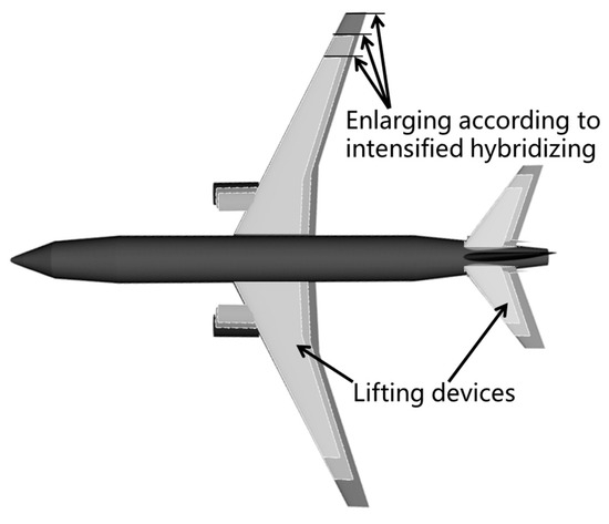
Figure 1.
Geometry and dimensional changes of lifting devices in accordance with aerodynamic requirement.
At low hybridising levels, only a fraction of fuel consumption is replaced by electricity (). For example, taxiing alone is partially electrified to lower the noise and emissions around the airport. It is desirable to offset some kerosene consumption () with electricity consumption considering the growing shortage of kerosene, which is a non-renewable energy source. However, hybridising also has the potential to consume more (rather than less) kerosene, since extra fuel () is required with increasing hybridising levels. Therefore, it is necessary to establish the boundary between those two situations (also shown in Figure 2), indicating the fuel-saving design space to avoid unexpected fuel wastage.
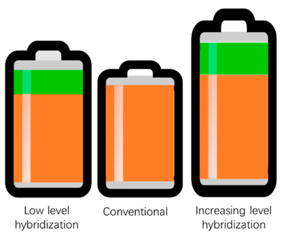
Figure 2.
Classic hybridisation results in different degrees of hybridisation.
The position of the boundary describing the fuel-saving design space is determined by various parameters including technological indicators, the mission of the aircraft, the degree of hybridisation, etc. Numerical design experiments based on a multidisciplinary optimisation design platform are promising as a means to help solve this problem.
2.2. Framework of Process for the Numerical Experiment on Hybridisation
The purpose of this study is to provide insights into design strategies used to achieve the balance between improved energy efficiency and the resultant mass penalty for HEA. Based on the conditions described above, hybridisation is implemented by increasing the installed power of the embedded EM, which is step B of the framework. As the power of EM grows from 0 MW to 70 MW to partially replace the power of the ICE, the integrated HEA is redesigned accordingly. The performance of these new designs is compared to the baseline. Understanding the trend of each key indicator is essential for the design space selection and appropriate hybridising of the target aircraft. To achieve this, a series of hybridising design experiments were carried out.
In summary, the framework of exploring the design space of HEA is illustrated in Figure 3, which facilitates pursuing the further benefits of HEA at the conceptual design stage. ‘Step A’, or designing the instances of the design experiment, requires an optimisation process (implemented using GENUS [6,53,54,55,56]) to take geometry, the propulsion system, mass estimation, performance evaluations and their coupling situations into account in the HEA design. For HEA, the classic HEP powertrain and power management strategies were added to the design process. All activated modules were validated in terms of both design and analysis [6], so it is applicable to support ‘Step A’ in the exploration framework (Figure 3). The hybrid-electric relevant multi-objective method is restricted in the specified research field [57]. The crucial obstacle to applying a multi-objective algorithm is that minimum MTOM is always being set as the common objective, whose importance cannot readily be overshadowed by others, so other objectives can only be paid attention to as a secondary priority. To overcome this limitation, a method of multi-objective design framework is proposed (‘Step B’) and carried out based on design method ‘Step A’. In ‘Step B’, authors process the design experiments by seeking for four key performance optimisation goals (i.e., fuel consumption, energy consumption, cost performance and emissions) that attract stakeholders considering the minimising MTOM. According to the logic relationship, the whole optimisation framework avoids the ignoring of crucial design factors (e.g., battery SoC [49]) in contrast to equivalent consumption minimisation strategies. The positive design space of HEA can be determined from this analysis by comparing these key aircraft performance indicators. A lighter and cheaper aircraft is always the preferred objective of the design (Table 2). The constraints applied in the optimisation are selected to ensure the following aspects.
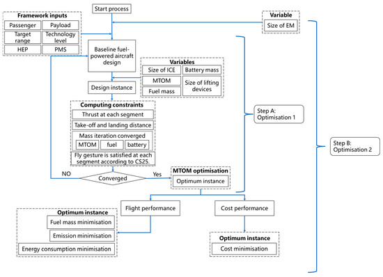
Figure 3.
Overview of two-step optimisation framework for exploring the balancing of the hybrid-electric aircraft design.

Table 2.
Objective and design variables for optimisations in Step A.
- The aircraft carries sufficient but not excessive amounts of fuel and battery;
- The mass iteration converges within an error of 5%;
- Take-off and landing distance requirements are met;
- The propulsion system meets the thrust requirement in each flight segment;
- The wing is sized according to a constant wing loading and aerodynamic requirements through all flight segments;
- The flightpath associated criteria in CS-25 [58] for each flight segment are met;
- The targeted flight range of the aircraft is met.
In the cost optimisation process of ‘Step B’, since electricity is cheaper energy compared with fuel, the replacement of fuel by electricity can be reflected in the energy cost () that can be expressed as in Equation (9), where and are the fuel and electricity costs respectively.
The flight-operational cost (FOC) is calculated based on Equation (10), where FOC is constituted by battery cost (), energy cost (), crew cost () and airport cost ().
Here, depends on the total mass, in turn affected by . The trade-off between fuel-saving benefits and mass penalties can also be manifested in cost performance, which is key for stakeholders.
2.3. Scope of the Numerical Experiment on Hybridisation
The essence of hybridisation of aircraft is to gradually replace conventional power with electrical power and to replace conventional fuel with electricity, forming a transformation in both the power provider and the energy source. This article aims to adopt a general architecture with a wide range of operating modes for both power splitting and energy splitting, which allows to change from zero to one as well as consume energy from pure kerosene to pure electricity at any flight segment (0 ≤ ≤ 1). The power flow is split between the EM and the ICE, resulting in a parallel energy flow in Figure 4, which can realise three powertrains: battery-kerosene powertrain, kerosene-powered powertrain and battery-powered powertrain. Hence, the EM and the ICE are combined and mechanically connected to the fan to guarantee that they can work either independently or collaboratively. Where the EM has not been put to work, the powerplant is regarded as a turbofan (Figure 4a). Alternatively, as the EM gradually replaces the ICE, the powerplant can transform into an all-electric one (Figure 4b). When the case is between these two extremes, the powerplant can be regarded as an EM that is embedded in the tail cone of a turbofan. In this article, shrinking the ICE while enlarging the embedded EM is the proposed method to raise the (Figure 4c). In this way, the design prevents mass redundancy from the replaced ICE provided that the thrust is sufficient.
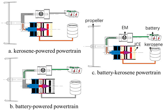
Figure 4.
Independently parallel hybrid propulsion architecture: (a) kerosene-powered powertrain, (b) battery-powered powertrain, (c) battery-kerosene powertrain.
In this investigation, the flight mission is separated into eight flight segments, from taxi out to taxi in (Figure 5). The power operation strategy of the HEP can be manifold. The main power management strategy adopted throughout the mission was the ‘electricity preferred strategy’, which maximised the usage of electricity and improved the efficiency of the propulsion system. There are two forms of expression in the airline: both throttles are in full throttle state at the take-off, climb, and landing segments; and the ICE is supplementary—needed only while the electric power is not enough to meet the segment requirement (e.g., cruise segment), but shut down during the flight when the electrical power is sufficient to work independently (e.g., descend segment and taxi segments). This operation strategy is considered the appropriate PMS corresponding to the technology that will have significantly improved by 2050, as well as the closest (most ready) to transfer to the all-electric mode. Specifically, the battery technology is anticipated to be improved to a sufficient level to realise the ambitious degree of hybridising. If not, the usage of electrical power should be optimised to limited periods during the whole mission.
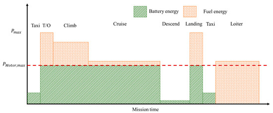
Figure 5.
Definition of battery operation strategy: maximum battery energy usage depending on EM power sizing.
In the process of aircraft design, aerodynamic devices need to be sized and redesigned in the optimisation stage so as to meet aerodynamic requirements throughout the whole flight. In this study, wing sizing complies with a constant wing loading of 645 kg/m2 and a wing aspect ratio of 11.6. Considering the stability and layout design of the aircraft, part of the luggage space is replaced by the accommodation of batteries and electrical accessories, which are distributed symmetrically around the centre of gravity. As a result, the battery storage is constrained by the underfloor space including the luggage volume. The volume of the battery is affected by the battery specific volume (unit: kg/m3).
According to the airworthiness regulation for large aeroplanes (i.e., CS-25) [58], the aeroplane is requested to meet specific requirements at each flight segment. The sizing of the propulsion system is based on those regulations to enable the design to cope with extreme conditions such as the ‘one engine inoperative’ condition and to complete the flight as requested by the mission. Such a hybrid-electric, narrow-body, twin-engine aircraft is designed in this study, targeting an entry into service year of 2050. The applied electrical technological level is predicted and parameterised according to the predictions carried out by Kuhn [59], Gerssen-Gondelach [60], Gogolák [51], and Delhaye [61]. Significantly, relevant technologies are developing fast, such as supercapacitors, superconducting technology, etc. Their key associated technical indicators are classified and listed in Table 3.

Table 3.
Specifications of the estimated technologies.
Only the state of charge (SOC), which has a significant impact on the overall mass of the aircraft, is considered in the following design. In addition, factors affecting electrical systems such as thermal management, charge and discharge rate, and dynamic behaviour are not considered in the design model of this paper. This is because the major design obstacle to the integration of the electrified aircraft is the weight penalty imposed by the battery; while the battery SOC needs to be tracked during the performance calculation, which needs to be kept above the safe value. In further modelling in future studies, the detailed design aspects of the battery as described above needs to be considered to make it more practical.
2.4. Fuel-Powered Baseline Aircraft
This part describes an advanced kerosene-powered twin-engine high aspect ratio aircraft as the baseline for the design experiment. A variety of propulsion arrangements and sizing tasks are conducted based on the baseline design, which includes the complete configuration from the viewpoint of the mission, geometry, mass breakdown, propulsion, performance, packaging, stability and cost, detailed hereafter.
The HEA designs are derived from their initial mission requirements that are shown in Table 4, including the common requirements of large airliners and technology challenges. The baseline aircraft (the sketch of which is shown in Figure 6) is equipped with two large-bypass specified turbofans. All flight segments are operated under the ‘kerosene-powered conventional’ mode and are defined according to the ICAO Annex 6 [62]. The cost-related settings are predicted according to the current state of the market.

Table 4.
Mission requirements of the baseline design.
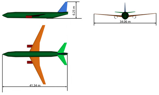
Figure 6.
Three-view drawing of the baseline design.
3. Results and Discussion
Section 2 presents the thinking behind and arrangement of the exploration of the HEA design. In this section, the exploration results are summarised and discussed, explaining the effects of hybridising on the key performance areas of the designed HEA, as elaborated in Section 3.1, Section 3.2 and Section 3.3 respectively. In addition, the positive design area indicating the condition of fuel-saving in the design space of HEA is elucidated, and the optimum design point highlighted, as discussed in Section 3.4.
3.1. The Effects of Hybridising on Mass and Energy
The key effects of hybridising are reflected in mass and energy changes, which is analysed in this section. Figure 7 shows the mass breakdown of all instances in this design experiment, highlighting the variation in battery mass (), fuel mass () and MTOM. Apparently, increases monotonously with increasing installed power of the EM (or with increasing size of the EM). By contrast, follows a different trend with its minimum point (i.e., minimum fuel consumption) being observed when the installed power of the EM equals 18 MW. The MTOW of the aircraft, which is composed of , and other types of mass (e.g., structural, system, operational masses, etc.), increases with EM, consistent with the theoretical prediction introduced in Section 2.1. More importantly, the experiment answered the question proposed at the end of Section 2.1.
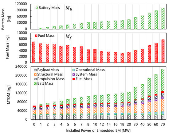
Figure 7.
The variation of MTOM and its breakdown (e.g., battery and fuel mass) at different hybridising levels.
In Figure 7, the existence of the design point with minimum fuel consumption demonstrates that the tendency of reduction, which results from replacing fuel with electricity, outweighs the tendency of increase. This latter is ascribed to the requirement of extra fuel to compensate for MTOM increase, when the EM power ranges between 0 and 18 MW. If the EM size further increases to a power greater than 18 MW, the above trend is reversed, hence the actual of the HEA increases despite the application of electric power and electricity. This phenomenon coincides well with the theoretical depiction of the potential fuel-saving design space described in Section 2.1.
Figure 8 further presents the growth ratio of MTOM (α-MTOM) with increasing EM size, along with that of energy efficiency (α-); is calculated using Equation (11), where t is the endurance and represents the instantaneous . It demonstrates that α-MTOM and α- decrease consistently when the installed EM power ranges from 0 to 18 MW, implying that the required energy by HEA, remains stable at this range; the value of depends on the competition between α-MTOM and α-, where greater α-MTOM results in increased , whereas improved α- leads to energy saving (i.e., reduced ). As EM becomes greater, α- approximately remains 1.0, implying that hardly changes, leading to greater required by growing MTOM (α-MTOM > 1.0); this trend of is due to the similar increasing rate between the required fuel and electricity.
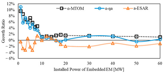
Figure 8.
Comparison between MTOM, average efficiency and in terms of their growth ratios.
More specifically, the energy performance can be represented by the energy specific air range (, unit: m/J), acting as a figure-of-merit for HEA optimisation [63,64]. The obtained growth ratio of (α-) with increasing EM size is also shown in Figure 8, demonstrating that fluctuates (α- 1.0) when the EM power is lower than 18 MW but is reduced ( < 1.0) as larger EM is installed. stands for the capability of energy transformation, hence the trend of its variance is opposite to that of .
3.2. The Effects of Hybridising on the Degree of Hybridisation for Power and Energy
The balancing design of HEA is essentially a trade-off associated with power splitting. With the shrunken core engine and the enlarged EM, the performance of the HEP is redesigned and optimised according to overall aircraft requirements. With the various values of electric throttle (x-axis) and conventional GT throttle (y-axis) which separately control the electric power usage proportion and the flow of fuel of ICE, the thrust and specific energy consumption (SEC in J/N/s) at the condition of static sea level are compared in Figure 9, each row representing a HEP equipped with a different size of EM (6, 12, 18 MW). The figure shows that the replacement of ICE by EM, whose installed power changes from 6 MW (a,b) to 18 MW (e,f), brings the benefit of improved (i.e., lowered) SEC.
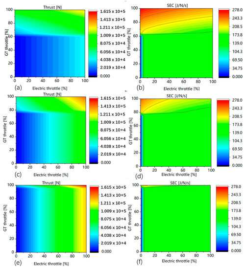
Figure 9.
Hybrid-electric thrust and specific energy consumption (SEC) at the static sea level flight condition: (a,b) aircraft hybridised by 6 MW EM; (c,d) aircraft hybridised by 12 MW EM; (e,f) aircraft hybridised by 18 MW EM.
However, In Figure 10, the ICE of HEP can provide redundant power when its size is reduced to a certain level. The relative change of thrust and MTOM have a similar trend between 0 and 20 MW, but split thereafter, implying the overall capability of the HEP is increased with hybridising levels and surpasses the requirement of HEA during the latter flight segment, because ICE cannot shrink continuously before it disappears. The idle flight segment should be considered while replacing ICE with EM. In order to maximise the role of ICE during the design of HEP, it is necessary to obtain the lower design boundary of ICE, which determines the efficient upper boundary of EM.
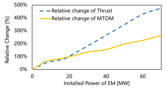
Figure 10.
Comparison of the relative change of thrust and MTOM.
In terms of the whole mission, Figure 11 shows how the whole flight is gradually electrified for each flight segment, with the sizes of EM enlarging (represented by the installed power of EM increasing). The taxiing segment can be fully electrified as the installed power increase from 1 to 2 MW because it requires less power. By contrast, the cruise segment is not fully electrified until the installed power grows from 6 to 8 MW because it requires larger power than the taxiing segment; while the final climb segment is fully electrified as the installed power grows from 16 to 18 MW. Therefore, the near-field (e.g., taxiing in and out) flight segments can be granted priority in consuming electricity. This can potentially bring benefits in reducing the mass of the embedded battery in the plane by replacing it with external ones on the ground. In addition, promoting electrification during the near-field flight segments can also reduce the pollution level around the airport. On the contrary, take-off, climbing and landing segments can be fully electrified with larger EM (i.e., larger installed power). They are target flight segments whose power peak needs to be shaved (i.e., shrinking the size of ICE), which is a key benefit of hybridising. Following this trend, all flight segments are expected to be purified if sufficiently advanced technology is available. However, the benefits of hybridising and the mass penalty are still necessary to be balanced, considering the current technological limit on batteries. Figure 12 further demonstrates the same trend from the perspective of the hybridisation degree for energy (). Increasing the EM size while shrinking the ICE simultaneously intends to actively increase , and consequently to affect . As shown in Figure 13, although the trend of was supposed to be consistent to that of (i.e., having a constantly increasing trend), the increase in cannot catch up with that in when the installed power becomes larger than 8 MW, which results from the technical limitation of batteries.
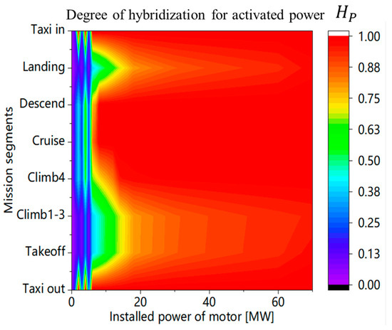
Figure 11.
The variation of for complete flight conditions of HEA with different levels of EM power.
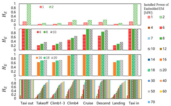
Figure 12.
The variation of for complete flight conditions of HEA with different levels of EM power.
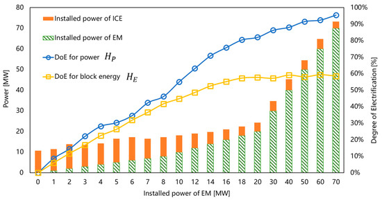
Figure 13.
The variation in installed power of each power generator, and with different levels of EM power.
In Figure 13, increases rapidly to around 0.8 when the power of EM reaches 18 MW, with the subsequent rate of increase greatly reduced until approaches 1.0 when the power of EM grows to 70 MW. By contrast, the increase of is restricted to the maximum value of 0.6 due to the restriction in the applied technology. This phenomenon demonstrates that electrical power is better able to meet the requirement of hybridisation than stored electrical energy. Therefore, improving the level of hybridisation depends on the specific energy () of the energy source, which is consistent with the theoretical analysis discussed in Section 2.1.
3.3. The Effects of Hybridising on Cost Performance
Cost performance is the most relevant performance of the aircraft to stakeholders. This section illustrates and analyses the variation in cost performance throughout the whole mission for all instances in the computational design experiment. The trend in shown in Figure 14 is similar to that of the block fuel mass (Figure 7), reaching the lowest value as the aircraft is equipped with an 18 MW EM. This is attributed to the fact that (unit price: 0.03 USD/kWh) is much cheaper than (unit price: 6 USD/USG), which therefore dominates . The change in FOC with increasing EM size is also shown in Figure 14, demonstrating that FOC is dominated by . In addition, the Cost-Specific Air Range (COSAR) proposed by C. Pornet [65] is considered in this study. It is expressed in Equation (12), where and represent the unit prices of electricity and fuel, respectively. COSAR is regarded as an assistant indicator to help designers optimise the performance of HEA. Its variation with increasing hybridising levels is shown in Figure 15, which will be discussed in Section 3.4.
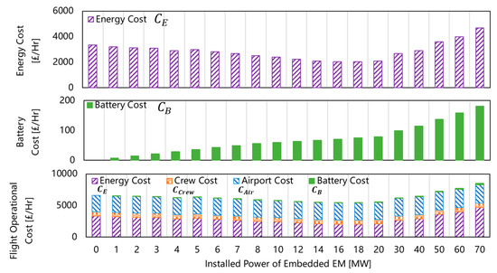
Figure 14.
Variation in FOC with different levels of EM power.
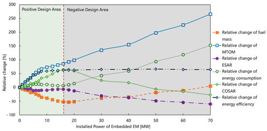
Figure 15.
Relative change in energy consumption, energy efficiency, MTOM, fuel mass, COSAR, and energy specific air range (ESAR) with different levels of EM power.
3.4. Determination of the Positive Design Area
Based on the results presented in the preceding sections, the relative change in the HEA performance compared with the baseline airliner regarding mass, energy and cost are summarised in Figure 15, which illustrates the design space of HEA. The positive design space is defined to include design instances which achieve a considerable advantage having paid for the cost of substitution. In the investigation of this paper, the design space is analysed from the point of view of the relative change in critical indicators: MTOM, , ESAR, , COSAR and ŋ. This partially qualitative analysis can be widely used on HEA with various missions. According to the trends summarised in Section 3.1, Section 3.2 and Section 3.3, the design space for HEA shown in Figure 15 can be divided into the positive and negative design areas; the positive area outlines the outstanding design space within the feasible design space for HEA, and features benefits including high energy efficiency (represented by ESAR), gently increasing MTOM, decreasing fuel consumption, increasing COSAR and fluctuating energy consumption. These benefits can be maximised at the optimum design point (i.e., EM power equals 18 MW for the current case) for HEA. The flight performance areas listed in Table 5 highlight and quantify the benefit of the optimised HEA in terms of energy consumption saving (by 44.52%), fuel-saving (by 65.56%), flight cost saving (by 16.4%), cost per seat saving (by 10.42%), and emission problem relief (by 44.58%). By contrast, the negative design area marks the design space that needs to be avoided due to non valuable performance: the increase of MTOM is the main penalty for hybridising, and the excessive growth of MTOM with little performance improvement is a representative phenomenon of the negative area.

Table 5.
Performance comparison between the advanced fuel-powered aircraft with the optimum hybridised aircraft in this study.
However, with the increasing power of the embedded EM, while electric energy undertakes more work, it is impossible for airliners to transit from the hybrid-electric mode to the all-electric mode at the technology level applied in this study. Conversely, it might result in an increase in fuel consumption. Thus, hybridisation of the airliner lacks significance if the EM size is larger than the optimum design point (i.e., the negative area), since that is when the energy consumption and MTOM increase sharply while the energy efficiency is hardly improved, and the consumed extra energy can barely bring any further fuel substitution, as illustrated in Figure 15.
Overall, the design space explored in this paper reveals the way in which HEA design advantages are applied to large airliners in the future, rather than designing for pure electric as this is currently regarded as a much longer-term objective. This exploration not only highlights the necessity of developing HEA, but also applies a two-steps multi-disciplinary optimisation framework of appropriately designing it in terms of balancing the quantified performance aspects regarding different disciplines (e.g., mass, energy consumption and cost). For each design instance, the whole computational design experiment follows the common philosophy of designing aircraft (i.e., minimum MTOM), while also considering the specific objective for HEA—designing HEA in the practical design zone and with reference to elements of practical significance.
4. Conclusions
This study was carried out to explore the design space of hybrid-electric aircraft on large hybrid-electric civil airliners. It focuses on the balancing design between the benefits and penalties resulting from the hybridising of airliners, and seeks the optimum design method for future design and demonstration. The study can be summarised as follows:
- (1)
- A two-step multi-objectives optimisation framework is introduced to explore the design space of HEA. The framework considers designing the lightest aircraft first and then covers further objectives such as minimum fuel consumption, minimum energy consumption, minimum cost, etc. It realises the multi-objective optimisation of HEA avoiding the ignoring of crucial design factors, assuring the general objectives alongside specified ones for HEA;
- (2)
- A series of design experiments were carried out by applying the framework with the installed power of the EM changing from 0 MW to 70 MW, taking a fuel-powered narrow-body airliner as the design baseline. The design space is identified and the positive design area for HEA can be distinguished through the analysis of performance indicators that need to be optimised.
- (3)
- An optimum design point is achieved and verified as the minimum fuel design point to classify the design space into the positive and negative areas. The mass penalty caused by hybridising can be partially compensated including by the chance that technology improvement will minimise it, while the degree of hybridisation is continuously intensified in the positive design area.
- (4)
- Along with the promising performance at the critical design point—confirmed by a fuel-saving of 65.56% in our experiment—75% COSAR improvements and 44.58% CO2 reduction is calculated with 60% HE.
- (5)
- The design space was classified into two areas which are helpful for the future study, application, and exploration of HEA. Theoretically, the design should be kept in the positive area and get close to the critical line in the design space. The optimum design point reflects the general design requirement of aircraft as well as the specific design goal of HEA, balancing the benefit with mass penalty.
- (6)
- The study in this paper clarifies the superiority of HEA in fuel saving, energy efficiency improvement, and cost benefits, in addition to playing a role in the transition period towards a zero-carbon emission future.
Author Contributions
Conceptualization, L.K. and H.S.; methodology, L.K.; software, L.K. and Y.S.; validation, L.K. and H.S.; formal analysis, L.K.; investigation, L.K.; resources, L.K.; data curation, L.K.; writing—original draft preparation, L.K.; writing—review and editing, L.K., H.S. and J.M.; visualization, L.K. and J.M.; supervision, H.S. and J.M.; project administration, H.S.; funding acquisition, L.K. All authors have read and agreed to the published version of the manuscript.
Funding
This work was financially supported by the Basic Strengthening Program Technical Area Fund of China, grant number 2021-JCJQ-JJ-0332.
Data Availability Statement
Data is contained within the article.
Conflicts of Interest
The authors declare no conflict of interest.
Nomenclature
| Acronyms | |
| COSAR | cost-specific air range [m/£] |
| EM | electric motor |
| ESAR | energy specific air range[m/J] |
| FOC | flight operational cost [£] |
| HV | heat value [Joule/kg] |
| HEA | hybrid-electric aircraft |
| HEP | hybrid-electric propulsion |
| ICE | internal combustion engine |
| MDAO | multidisciplinary design analysis and optimisation |
| MTOM | maximum take-off mass [kg] |
| PMS | power management strategy |
| USD | United States dollar |
| USG | United States gallon |
| SEC | specific energy consumption |
| Symbols | |
| specific cost consumption [£/kWh] | |
| C | cost [£/Hr] |
| D | drag [N] |
| L | lift [N] |
| H | degree of hybridisation |
| gravitational acceleration [m/] | |
| mass of fuel-powered aircraft [kg] | |
| mass of hybrid-electric aircraft [kg] | |
| block energy of fuel-powered aircraft [Joule] | |
| block energy of HEA [Joule] | |
| flight speed [m/s] | |
| range [m] | |
| ratio of mass comparison | |
| practical ratio of mass comparison | |
| TSPC | specific power consumption [Watt/N] |
| endurance [s] | |
| energy efficiency | |
| specific energy [kWh/kg] | |
| weight number of kerosene | |
| activation ratio | |
| Prefix/Subscripts | |
| B | battery |
| E | energy |
| M | mass |
| f | fuel |
| m | motor |
| P | power |
| ins | instantaneous |
References
- Federal Aviation Administration. FAA Aerospace Forecast Fiscal Years 2020–2040; FAA: Washington, DC, USA, 2020; pp. 1–7. [Google Scholar]
- Krein, A.; Williams, G. Flightpath 2050: Europe’s Vision for Aeronautics; Publication Office of the European Union: Bruxelles, Belgium, 2012; Volume 30. [Google Scholar] [CrossRef]
- JPI Urban Europe. Strategic Research and Innovation Agenda 2.0; JPI Urban Europe: Vienna, Austria, 2019. [Google Scholar]
- Isikveren, A.T.; Kaiser, S.; Pornet, C.; Vratny, P.C. Pre-Design Strategies and Sizing Techniques for Dual-Energy Aircraft. Aircr. Eng. Aerosp. Technol. 2014, 86, 525–542. [Google Scholar] [CrossRef]
- Finger, D.F.; Bil, C.; Braun, C. Initial Sizing Methodology for Hybrid-Electric General Aviation Aircraft. J. Aircr. 2020, 57, 245–255. [Google Scholar] [CrossRef]
- Kang, L.; Sun, Y.; Smith, H. MDAO Method and Optimum Designs of Hybrid-Electric Civil Airliners. J. Aerosp. Eng. 2022, 35, 1–19. [Google Scholar] [CrossRef]
- Isikveren, A.T.; Pornet, C.; Vratny, P.C.; Schmidt, M. Optimization of Commercial Aircraft Using Battery-Based Voltaic-Joule/Brayton Propulsion. J. Aircr. 2017, 54, 246–261. [Google Scholar] [CrossRef]
- Isikveren, A.T. The Method of Quadrant Based Algorithmic Nomographs for Hybrid/Electric Aircraft Pre-Design. J. Aircr. 2018, 55, 394–403. [Google Scholar] [CrossRef]
- Isikveren, A.T.; Fefermann, Y.; Maury, C.; Level, C.; Zarati, K.; Salanne, J.-P.; Pornet, C.; Thoraval, B. Pre-Design of a Commuter Transport Utilising Voltaic-Joule/Brayton Motive Power Systems. Aeronaut. J. 2018, 122, 205–237. [Google Scholar] [CrossRef]
- Finger, D.F.; de Vries, R.; Vos, R.; Braun, C.; Bil, C. Cross-Validation of Hybrid-Electric Aircraft Sizing Methods. J. Aircr. 2022, 1–19. [Google Scholar] [CrossRef]
- De Vries, R.; Hoogreef MF, M.; Vos, R. Range Equation for Hybrid-Electric Aircraft with Constant Power Split. J. Aircr. 2020, 57, 552–557. [Google Scholar] [CrossRef]
- Harmon, F.G.; Frank, A.A.; Chattot, J.J. Conceptual Design and Simulation of a Small Hybrid-Electric Unmanned Aerial Vehicle. J. Aircr. 2006, 43, 1490–1498. [Google Scholar] [CrossRef]
- Friedrich, C.; Robertson, P.A. Hybrid-Electric Propulsion for Aircraft. J. Aircr. 2015, 52, 176–189. [Google Scholar] [CrossRef]
- Dean, T.S.; Wroblewski, G.E.; Ansell, P.J. Mission Analysis and Component-Level Sensitivity Study of Hybrid-Electric General-Aviation Propulsion Systems. J. Aircr. 2018, 55, 2454–2465. [Google Scholar] [CrossRef]
- Bradley, M.K.; Droney, C.K. Subsonic Ultra Green Aircraft Research: Phase I Final Report; NASA Technical Report; NASA: Washington, DC, USA, 2011; Volume CR-2011-21, p. 207. [Google Scholar]
- Bradley, M.K.; Droney, C.K. Subsonic Ultra Green Aircraft Research Phase II–Volume II–Hybrid Electric Design Exploration; NASA CR-218704; NASA: Washington, DC, USA, 2015; Volume I, p. 378. [Google Scholar]
- Perullo, C.A.; Dimitri, P.; Mavris, N. Assessment of Vehicle Performance Using Integrated NPSS Hybrid Electric Propulsion Models. In Proceedings of the 50th AIAA/ASME/SAE/ASEE Joint Propulsion Conference, Cleveland, OH, USA, 28–30 July 2014. [Google Scholar] [CrossRef]
- Owano, N. SUGAR Volt: Boeing Puts Vision to Work in Hybrid Electric Aircraft. Phys.org 2012. [Google Scholar]
- Norris, G. Airbus And Rolls-Royce Freeze E-Fan X Hybrid- Electric Demo Design; Aviation Week Network: New York, NY, USA, 2019; pp. 2020–2021. [Google Scholar]
- Robinson, T. How E-Fan X Will Jump-Start a New Era in Hybrid-Electric Flight; Royal Aeronautical Society: London, UK, 2017; pp. 1–15. [Google Scholar]
- Stein, P. The E-Fan X Programme. In Our Stories—The E-Fan X Programme; Rolls-Royce. 2020. Available online: https://www.rolls-royce.com/media/our-stories/insights/2018/paul-stein-talks-about-e-fan-x.aspx (accessed on 1 January 2023).
- Warwick, G.; Osborne, T. Airbus E-Fan X To Pave Way For Electric Regional Aircraft. Aviat. Week Space Technol. 2017, 1–3. [Google Scholar]
- Riboldi, C.E.D. An Optimal Approach to the Preliminary Design of Small Hybrid-Electric Aircraft. Aerosp. Sci. Technol. 2018, 81, 14–31. [Google Scholar] [CrossRef]
- Rippl, M.D. Sizing Analysis for Aircraft Utilizing Hybrid—Electric Propulsion Systems; Air Force Institute of Technology: Wright-Patterson AFB, OH, USA, 2011. [Google Scholar]
- Pornet, C. Conceptual Design Methods for Sizing and Performance of Hybrid-Electric Transport Aircraft. Disseration Thesis, Technische Universität München, München, Germany, 2018. [Google Scholar]
- Ang AW, X.; Gangoli Rao, A.; Kanakis, T.; Lammen, W. Performance Analysis of an Electrically Assisted Propulsion System for a Short-Range Civil Aircraft. Proc. Inst. Mech. Eng. Part G J. Aerosp. Eng. 2019, 233, 1490–1502. [Google Scholar] [CrossRef]
- Perullo, C.A.; Tai, J.; Mavris, D. A New Sizing and Synthesis Environment for the Design and Assessment of Advanced Hybrid and Electric Aircraft Propulsion Systems; ISABE: Indianapolis, IN, USA, 2015. [Google Scholar]
- Gladin, J.; Trawick, D.; Perullo, C.; Tai JC, M.; Mavris, D.N. Modeling and Design of a Partially Electric Distributed Aircraft Propulsion System with GT-HEAT. In Proceedings of the AIAA SciTech Forum—55th AIAA Aerospace Sciences Meeting, Grapevine, TX, USA, 9–13 January 2017; pp. 1–18. [Google Scholar] [CrossRef]
- Perullo, C.A.; Tai JC, M.; Mavris, D.N. Development of a Suite of Hybrid Electric Propulsion Modeling Elements Using NPSS. In Proceedings of the ASME Turbo Expo 2014: Turbine Technical Conference and Exposition, Düsseldorf, Germany, 16–20 June 2014. [Google Scholar]
- Gladin, J.C.; Trawick, D.; Mavris, D.; Armstrong, M.; Bevis, D.; Klein, K. Fundamentals of Parallel Hybrid Turbofan Mission Analysis with Application to the Electrically Variable Engine. In Proceedings of the 55th AIAA Aerospace Sciences Meeting, Grapevine, Texas, 9–13 January 2017. [Google Scholar]
- Antcliff, K.R.; Capristan, F.M. Conceptual Design of the Parallel Electric-Gas Architecture with Synergistic Utilization Scheme (PEGASUS) Concept. In Proceedings of the 18th AIAA/ISSMO Multidisciplinary Analysis and Optimization Conference, Denver, CO, USA, 5–9 June 2017. [Google Scholar] [CrossRef]
- Introduction, P.; Benefits, A. Hybrid-Electric Aircraft TOGW Development Tool with Empirically—Based Airframe and Physics-Based Hybrid Propulsion System Component Analysis, Phase I; Tech-Port of NASA; California and Ohio. 2013, pp. 3–5. Available online: https://worldwidescience.org/topicpages/h/hybrid-electric+propulsion+systems.html (accessed on 30 November 2021).
- Geiß, I.; Strohmayer, A.; Notter, S.; Fichter, W. Optimized Operation Strategies for Serial Hybrid-Electric Aircraft. In Proceedings of the 2018 Aviation Technology, Integration, and Operations Conference, Atlanta, GA, USA, 25–29 June 2018. [Google Scholar] [CrossRef]
- Hoelzen, J.; Liu, Y.; Bensmann, B.; Winnefeld, C.; Elham, A.; Friedrichs, J.; Hanke-Rauschenbach, R. Conceptual Design of Operation Strategies for Hybrid Electric Aircraft. Energies 2018, 11, 217. [Google Scholar] [CrossRef]
- Pinto Leite JP, S.; Voskuijl, M. Optimal Energy Management for Hybrid-Electric Aircraft. Aircr. Eng. Aerosp. Technol. 2020, 92, 851–861. [Google Scholar] [CrossRef]
- Voskuijl, M.; van Bogaert, J.; Rao, A.G. Analysis and Design of Hybrid Electric Regional Turboprop Aircraft. CEAS Aeronaut. J. 2018, 9, 15–25. [Google Scholar] [CrossRef]
- Xie, Y.; Savvaris, A.; Tsourdos, A.; Laycock, J.; Farmer, A. Modelling and Control of a Hybrid Electric Propulsion System for Unmanned Aerial Vehicles. In Proceedings of the IEEE Aerospace Conference, Big Sky, MT, USA, 3–10 March 2018; pp. 1–13. [Google Scholar] [CrossRef]
- Hoogreef MF, M.; Vos, R.; de Vries, R.; Veldhuis, L.L.M. Conceptual Assessment of Hybrid Electric Aircraft with Distributed Propulsion and Boosted Turbofans. In Proceedings of the AIAA Scitech 2019 Forum, San Diego, CA, USA, 7–11 January 2019. [Google Scholar] [CrossRef]
- Pornet, C.; Isikveren, A.T. Conceptual Design of Hybrid-Electric Transport Aircraft. Prog. Aerosp. Sci. 2015, 79, 114–135. [Google Scholar] [CrossRef]
- Hecken, T.; Zhao, X.; Iwanizki, M.; Arzberger, M.J.; Silberhorn, D.; Plohr, M.; Kyprianidis, K.; Sahoo, S.; Valente, G.; Sumsurooah, S.; et al. Conceptual Design Studies of ‘Boosted Turbofan’ Configuration for Short Range. In Proceedings of the AIAA Scitech 2020 Forum, Orlando, FL, USA, 6–10 January 2020; pp. 1–23. [Google Scholar] [CrossRef]
- Zhao, X.; Sahoo, S.; Kyprianidis, K.; Rantzer, J.; Sielemann, M. Off-Design Performance Analysis of Hybridised Aircraft Gas Turbine. Aeronaut. J. 2019, 123, 1999–2018. [Google Scholar] [CrossRef]
- Lents, C.; Hardin, L.; Rheaume, J.; Kohlman, L. Parallel Hybrid Gas-Electric Geared Turbofan Engine Conceptual Design and Benefits Analysis. In Proceedings of the 52nd AIAA/SAE/ASEE Joint Propulsion Conference, Salt Lake City, UT, USA, 25–27 July 2016; pp. 1–13. [Google Scholar] [CrossRef]
- Lents, C.; Hardin, L. Fuel Burn and Energy Consumption Reductions of a Single-Aisle Class Parallel Hybrid Propulsion System. In Proceedings of the AIAA Propulsion and Energy Forum and Exposition, Indianapolis, IN, USA, 19–22 August 2019; pp. 1–8. [Google Scholar] [CrossRef]
- Strack, M.; Chiozzotto, G.P.; Iwanizki, M.; Plohr, M.; Kuhn, M. Conceptual Design Assessment of Advanced Hybrid Electric Turboprop Aircraft Configurations. In Proceedings of the 17th AIAA Aviation Technology, Integration, and Operations Conference, Denver, CO, USA, 5–9 June 2017. [Google Scholar]
- Cameretti, M.C.; Del Pizzo, A.; Di Noia, L.P.; Ferrara, M.; Pascarella, C. Modeling and Investigation of a Turboprop Hybrid Electric Propulsion System. Aerospace 2018, 5, 123. [Google Scholar] [CrossRef]
- Pornet, C.; Gologan, C.; Vratny, P.C.; Seitz, A.; Schmitz, O.; Isikveren, A.T.; Hornung, M. Methodology for Sizing and Performance Assessment of Hybrid Energy Aircraft. In Proceedings of the 2013 Aviation Technology, Integration, and Operations Conference, Los Angeles, CA, USA, 12–14 August 2013. [Google Scholar] [CrossRef]
- Orefice, F.; Marciello, V.; Nicolosi, F.; Zhang, Q.; Wortmann, G.; Menu, J.; Cusati, V. Design of Hybrid-Electric Small Air Transports. IOP Conf. Ser. Mater. Sci. Eng. 2022, 1226, 012075. [Google Scholar] [CrossRef]
- Xie, Y.; Savvarisal Antonios, T.; Dan, Z.; Jason, G. Review of Hybrid Electric Powered Aircraft, Its Conceptual Design and Energy Management Methodologies. Chin. J. Aeronaut. 2020, 34, 432–450. [Google Scholar] [CrossRef]
- Sinoquet, D.; Rousseau, G. Design Optimization and Optimal Control for Hybrid Vehicles. Optim. Eng. 2009, 12, 199–213. [Google Scholar] [CrossRef]
- Aviation, E. World Jet Fuel Specifications with Avgas Supplement; Machelen ExxonMobil Aviation: Irving, TX, USA, 2008. [Google Scholar]
- Gogolák, L.; Csikós, S.; Molnár, T.; Szuchy, P.; Bíró, I.; Sárosi, J. Possibilities of Optimizing Fuel Consumption in Hybrid and Electronic Airplanes. Analecta Technica Szegedinensia 2019, 13, 65–76. [Google Scholar] [CrossRef]
- Friedrich, C.; Robertson, P.A. Hybrid-Electric Propulsion for Automotive and Aviation Applications. CEAS Aeronaut. J. 2015, 6, 279–290. [Google Scholar] [CrossRef]
- Smith, H.; Sziroczák, D.; Abbe, G.E.; Okonkwo, P. The GENUS Aircraft Conceptual Design Environment. Proc. Inst. Mech. Eng. Part G: J. Aerosp. Eng. 2019, 233, 2932–2947. [Google Scholar] [CrossRef]
- Sun, Y.; Smith, H. Low-Boom Low-Drag Solutions through the Evaluation of Different Supersonic Business Jet Concepts. Aeronaut. J. 2020, 124, 76–95. [Google Scholar] [CrossRef]
- Smith, H.; Rajendran, P. Review of the Elementary Aspect of Small Solar-Powered Electric Unmanned Aerial Vehicles. Aust. J. Basic Appl. Sci. 2014, 8, 252–259. [Google Scholar]
- Sepulveda, E.; Smith, H.; Sziroczak, D. Multidisciplinary Analysis of Subsonic Stealth Unmanned Combat Aerial Vehicles. CEAS Aeronaut. J. 2019, 10, 431–442. [Google Scholar] [CrossRef]
- Fang, S.; Xu, Y. Multiobjective Coordinated Scheduling of Energy and Flight for Hybrid Electric Unmanned Aircraft Microgrids. IEEE Trans. Ind. Electron. 2019, 66, 5686–5695. [Google Scholar] [CrossRef]
- European Aviation Safety Agency. Certification Specifications and Acceptable Means of Compliance for Large Aeroplanes; Amendment 24. 885; European Aviation Safety Agency: Köln, Germany; Available online: https://www.easa.europa.eu/en/certification-specifications/cs-25-large-aeroplanes (accessed on 30 November 2022).
- Kuhn, H.; Sizmann, A. Fundamental Prerequisites for Electric Flying. ResearchGate. 2012. Available online: https://www.researchgate.net/publication/271457393_Fundamental_Prerequisites_for_Electric_Flying (accessed on 30 November 2022).
- Gerssen-Gondelach, S.J.; Faaij, A.P.C. Performance of Batteries for Electric Vehicles on Short and Longer Term. J. Power Sources 2012, 212, 111–129. [Google Scholar] [CrossRef]
- Delhaye, J. Electrical Technologies for the Aviation of the Future. In Proceedings of the Hybrid Electric Propulsion-Europe-Japan Symposium, Tokyo, Japan, 26 March 2015. [Google Scholar]
- ICAO. ICAO Annex 6—Operation of Aircraft; ICAO: Montreal, OT, Canada, 2010. [Google Scholar]
- Schmitz, O.; Hornung, M. Unified Applicable Propulsion System Performance Metrics. Proc. ASME Turbo Expo 2013, 2, 1–12. [Google Scholar] [CrossRef]
- Seitz, A.; Schmitz, O.; Isikveren, A.T.; Hornung, M. Electrically Powered Propulsion: Comparison and Contrast to Gas Turbines; Deutsche Gesellschaft für Luft-und Raumfahrt-Lilienthal-Oberth eV: Bonn, Germany, 2012. [Google Scholar]
- Pornet, C.; Kaiser, S.; Gologan, C. Cost-Based Flight Technique Optimization for Hybrid Energy Aircraft. Aircr. Eng. Aerosp. Technol. 2014, 86, 591–598. [Google Scholar] [CrossRef]
Disclaimer/Publisher’s Note: The statements, opinions and data contained in all publications are solely those of the individual author(s) and contributor(s) and not of MDPI and/or the editor(s). MDPI and/or the editor(s) disclaim responsibility for any injury to people or property resulting from any ideas, methods, instructions or products referred to in the content. |
© 2023 by the authors. Licensee MDPI, Basel, Switzerland. This article is an open access article distributed under the terms and conditions of the Creative Commons Attribution (CC BY) license (https://creativecommons.org/licenses/by/4.0/).