Article

An Improved Fault Detection and Isolation Method for Airborne Inertial Navigation System/Attitude and Heading Reference System Redundant System

College of Automation Engineering, Nanjing University of Aeronautics and Astronautics, No. 29 General Avenue, Nanjing 211106, China
*
Author to whom correspondence should be addressed.
Aerospace 2023, 10(12), 1024; https://doi.org/10.3390/aerospace10121024
Submission received: 22 October 2023 / Revised: 4 December 2023 / Accepted: 8 December 2023 / Published: 11 December 2023

Abstract

:
The integrity of airborne inertial navigation systems (INSs) is the key to ensuring the safe flight of civil aircraft. The airborne attitude and heading reference system (AHRS) is introduced into the construction of a redundant inertial navigation system. As a backup system for an airborne INS, the AHRS exhibits a different device performance. A sequential weighted generalized likelihood ratio test (SWGLT) method, based on a principal component parity vector (PPV), is proposed. The PPV method improves the adaptability of the detection threshold to the inertial sensors’ noise and improves the probability of correct detection. At the same time, the multiscale problem of a heterogeneous redundant system error is solved by sequential weighting, and the false alarm rate is reduced. Simulation experiments show that the proposed method can improve fault detection sensitivity, reduce false alarm rates, and ensure the integrity of civil aircraft navigation systems.

1. Introduction

The required navigation performance (RNP) has become a trend in civil aviation [1,2,3,4]. Ensuring the high precision and high integrity of the navigation system is the key to realizing safe RNP flight in various weather and environmental conditions [5]. The integrity of airborne navigation systems refers to the measure of confidence in the accuracy of the navigation information, including the ability to locate faults and issue warnings in case of system failures.
Fault-tolerant navigation is the primary method of ensuring the integrity of the navigation system, including several key steps such as fault detection, fault isolation, and system reconfiguration, all of which rely on redundant information [6]. Currently, civil aircraft utilize integrated modular avionics (IMA) to integrate airborne navigation sensors, enabling the airborne flight management system (FMS) to use all redundant information onboard information to monitor the integrity of the navigation system [7].
An inertial navigation system (INS), as a completely autonomous navigation system, has strong anti-interference capabilities and good continuity, making it a crucial navigation reference system for civil aircraft [8]. Civil aircraft typically carry two to three sets of INSs (inertial navigation systems), including the primary, backup, and standby systems [9].
Redundancy technology can be divided into hardware redundancy and analytical redundancy. Aerodynamics models of aircraft are often used as analytic redundancy systems. As aerodynamics models does not require additional hardware devices, they represent a more economical approach to constructing a redundant system [10]. However, when the aerodynamic model is involved in fault detection for the redundant inertial system, its output requires preprocessing [11]. Moreover, the intricate airflow conditions during flight can result in sudden changes in the aerodynamic model’s output, diminishing the efficiency and accuracy of fault detection [12].
Based on the hardware redundancy, the voting strategy is a commonly used fault diagnosis method for a civil aircraft onboard INS. This method directly compares the outputs of multiple sets of INSs for fault diagnosis. The advantage of the voting scheme is its ease of implementation, but it is not sensitive to real-time faults and relies on extra hardware devices [13,14]. Most of the other fault detection methods for redundant systems are based on parity vector methods [15,16,17]. For systems that can obtain sufficient sensor-level redundant navigation outputs, these methods have a high fault detection performance. However, these methods are not applicable for FMSs that can only obtain two to three sets of system-level outputs.
The AHRS is an attitude measurement system that can provide attitude data, such as roll, pitch, and heading angle for aircraft; for example, the Honeywell’s AH-2000 AHRS is composed of a low-cost gyroscope, a micro-electro mechanical system (MEMS) accelerometer, and a magnetometer. The airborne AHRS primarily serves as a secondary source of attitude information. For example, a Boeing 787 is equipped with two sets of INSs a set of AHRSs, as a backup system. Nonetheless, the widespread adoption of IMA has enabled FMSs to harness the inertial sensor data provided by an AHRS as a hardware redundancy solution for INSs.
A fault-tolerant control algorithm, based on an unscented Kalman filter (UKF) or particle Kalman filter (PKF), has been recently researched for unmanned aerial vehicles (UAV). However, despite its capability for real-time fault correction and compensating for sensor fault drifts, the fault-tolerant control algorithm is sensitive to inaccuracies in prior knowledge of noise covariance and feedback gain [18]. Inappropriate estimates of these parameters can render the compensation algorithm ineffective. Moreover, its effective feedback gain range is narrow, demanding extensive experimentation for accurate determination [19]. This is unfavorable for the swift detection and localization of faults in civil aviation aircraft.
Methods based on a parity vector are commonly used for fault detection and the isolation of redundant systems, such as the optimal parity vector method (OPT), the singular value decomposition method (SVD), and the generalized likelihood test (GLT) method, all of which are based on the idea of spatial projection to isolate hard and soft faults in redundant systems. The GLT fault detection method has the advantages of small computational complexity, a low diagnostic delay, a low false alarm rate, and the ability to effectively detect both hard and soft faults. It is commonly used for fault detection in redundant systems. In addition, this method has high detection sensitivity and is easy to implement in engineering [20,21,22]. However, the GLT method relies on prior knowledge of the statistical characteristics of noise in redundant information and mainly focuses on the current error state of the redundant system. When there are noises with different statistical characteristics in the redundant system, composed of heterogeneous sensors, it reduces the detection efficiency of the GLT method [23,24]. In addition, the fault detection threshold of GLT is determined from the probability of a false alarm, is only sensitive to larger faults, makes it easy to cause a leakage alarm, and is insensitive to soft faults [25].
Therefore, this paper proposes a novel redundant system fault detection and isolation method for INSs. The architecture is shown in Figure 1. The first contribution is that the principal component fault indication function of each sensor is constructed by time sequence principal component tests of multiple parity vectors; the adaptive tolerance threshold is constructed to make the system more sensitive to faults and improve the accuracy of fault detection. The second contribution is that a weighted GLT (WGLT) method is proposed, by applying a weighted matrix to the GLT function, solving the problem of false alarms caused by multi-scale subsystem errors.

2. Traditional Generalized Likelihood Test Fault Detection for Redundant Systems

For a redundant system that generates n measurements, when a sensor may fail, the measurement equation of the system is:
Z = H X + f + ε
where Z R n represents the measured value matrix output by the redundant navigation system; H R n × m stands for the redundant system configuration matrix; X R m represents each measurement value of the redundant system; f represents the fault vector, where the element corresponding to the faulty navigation parameter is one, and the other elements are zero. ε R n stands for the redundant system measurement noise matrix, which satisfies ε ~ N ( 0 , σ ) .
According to the configuration of two INSs and one AHRS in the A320, the INS redundancy system studied in this paper is constructed, and the following settings are made:
(1)
The three sets of subsystems are installed in the same direction and are parallel, and the inertial devices can be unified to the same coordinate origin;
(2)
The inertial devices for each subsystem are mounted orthogonally in three axes.
Thus, the redundant system configuration matrix H in this paper is:
H = [ 1 0 0 1 0 0 1 0 0 0 1 0 0 1 0 0 1 0 0 0 1 0 0 1 0 0 1 ] T
We define a parity vector P as follows:
P = V Z = V H X + V f + V ε
where V is a full-rank parity matrix:
V H = 0 , V V T = I
In this case, the parity vector becomes:
P = V f + V ε
When the system is fault-free, the parity vector P is only related to the measurement noise. Therefore, the statistical characteristics of parity vector P under the fault-free hypothesis, H0, and the fault hypothesis, H1, are as follows:
H 0 :   P ~ N ( 0 , σ ) H 1 :   P ~ N ( μ , σ ) ,   σ = V f
We solve the logarithmic likelihood ratio of the probability density function under the two hypotheses f ( P | H 0 ) and f ( P | H 1 ) :
Λ ( P ) = log p ( P | H 0 ) p ( P | H 1 ) = P T P ( P μ ) T ( P μ ) 2 σ 2
The maximum likelihood estimate for µ can be obtained as:
μ ^ = P
Then, the maximum likelihood function value is:
Λ ( P ) = 1 2 σ 2 P T P
The fault detection decision function FD can be defined as:
F D = 1 σ 2 P T P
When the system is fault-free, the F D ~ χ 2 ( n 3 ) , the parity vector P is a Gaussian random vector.
{ F D < T D ,   H 0 : F a u l t   F r e e F D > T D ,   H 1 : F a u l t   o c c u r
where TD is the detection threshold. When a false alarm rate is given, it can be known by checking the Chi-square distribution table.
When a fault is detected, the redundant system isolates the fault. Assuming the fault of the ith sensor hypothesis is Hi, the statistical characteristic is:
H i :   E ( P f V i ) T ( P f V i ) = 0
where Vi is column i of parity matrix V, and the maximum likelihood estimate for fault size f is:
f ^ = P T V i V i T V i
The fault isolation function FI can be defined as:
F I ( i ) = ( P T V i ) 2 σ 2 V i T V i , i = 1 , 2 , , n
If F I ( k ) = m a x   F I ( i ) , it indicates that the kth subsystem has a fault.

3. Principal Component Parity Vector-Based Sequential Weighted Generalized Likelihood Ratio Test Fault Detection for Inertial Navigation System/Attitude and Heading Referential System Redundant System

3.1. Principal Component Parity Vector Method

The j time sequential independent samples of parity vector P are X = [ P ( 1 ) , P ( 2 ) , P ( 3 ) P ( j ) ] . The sequential parity vectors were evaluated by the PCA (principal component analysis) method to extract the true error characteristics of the subsystems.
The matrix X is normalized to zero mean and unit variance, and then the covariance matrix is decomposed by the eigenvalue.
Σ = Q Λ Q T
where Σ is the covariance matrix of X, Λ = d i a g ( λ 1 ,   λ 2 ,   λ 3 , , λ j ) is the diagonal eigenvalue matrix, within λ 1 > λ 2 > λ 3 > > λ j . Q = d i a g ( Q 1 ,   Q 2 ,   Q 3 , , Q j ) is the eigenvector matrix.
The eigenvalues and eigenvectors, whose cumulative contribution rate R exceeds the threshold value r, are selected as the retained principal components X r = [ P ( 1 ) , P ( 2 ) P ( s ) ] , and s is the number of retained parity vectors.
R = k = 1 i λ k k = 1 j λ k ( i = 1 , 2 , , j ) r
The principal component parity Pr can be obtained by probability statistics of the retained principal component Xr:
P r = M e a n ( X r )
Assuming the fault of the ith sensor hypothesis is Hi, the statistical characteristic is:
H i :   P i ~ N ( V i f s , σ )
where Vi is column i of parity matrix V, the maximum likelihood estimate for fault size fs is:
f ^ s = P T V i V i T V i
By substituting Equation (19) into Equation (17), the principal component fault function of the ith device can be obtained:
F I P P V ( i ) = P r T V i V i 2 , i = 1 , 2 , , n
If F I P P V ( k ) = m a x   F I P P V ( i ) , it indicates that the kth subsystem has a fault.

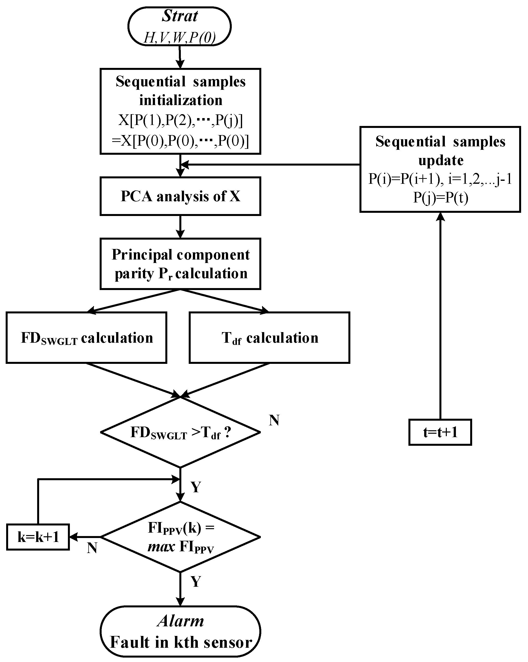
3.2. Principal Component Parity Vector-Based Sequential Weighted Generalized Likelihood Ratio Test Fault Detection

When the ith sensor fails, the redundant system triaxial measurements can be obtained by the least square method:
X ^ f = ( H T H ) 1 H T Z = ( H T H ) 1 H T ( H X + f + ε ) = X + ( H T H ) 1 H T ( f s e i + ε )
where ei is the fault vector, fs is the fault amplitude, the ith element is one, and the rest is zero. The estimated error covariance PKf of X ^ f is:
P K f = E [ ( X ^ f X ) ( X ^ f X ) T ] = f s 2 ( H T H ) 1 e i e i T ( H T H ) 1 + σ 2 ( H T H ) 1
Similarly, we calculate the system measurements and covariance after isolating the faulty sensor:
X ^ h = ( H T D i H ) 1 H T D i Z = X + ( H T D i H ) 1 H T D i ε
where Di is a diagonal matrix, Di(i,i) = 0, and the other elements on the diagonal are one.
The estimated error covariance PKh is:
P K h = E [ ( X ^ h X ) ( X ^ h X ) T ] = σ 2 ( H T D i H ) 1
Using the matrix inversion formula, Equation (21) can be reduced to:
P K h = σ 2 ( H T H H i T H i ) 1 = σ 2 ( H T H ) 1 + σ 2 ( H T H ) 1 H i [ 1 H i T ( H T H ) 1 H i ] 1 H i T ( H T H ) 1
According to Equation (4), the parity vector satisfies [26]:
V T V = I H ( H T H ) 1 H T
Then, PKh can be converted to:
P K h = σ 2 V i 2 ( H T H ) 1 e i e i T ( H T H ) 1 + σ 2 ( H T H ) 1
Then, the covariance difference Δ P K before and after system failure can be obtained:
Δ P K = P K f P K h = ( f s 2 σ 2 V i 2 ) ( H T H ) 1 e i e i T ( H T H ) 1
We let:
Δ P K = K σ 2
where Δ P K is the tolerable performance difference and K is the tolerance ratio factor.
In this case, the tolerable fault size ft is:
f t = σ K H T H ( e i e i T ) 1 H T H + 1 / V i 2
In order to solve the multi-scale error of the subsystem, parity vectors are normalized by weight matrix processing:
V W 1 Z = V W 1 H X + V W 1 f + V W 1 ε
within which:
W = d i a g ( σ 1 2 , σ 2 2 , σ n 2 )
where σ 1 2 , σ 2 2 , σ n 2 are the prior knowledge error chiastic of each inertial device, within which:
V W 1 H = 0 , V W 1 ( V W 1 ) T = I
Then, the principal component parity Pr, under the fault-free hypothesis H0 and fault hypothesis H1, is as follows:
H 0 :   P r ~ N ( 0 , 1 ) H 1 :   P r ~ N ( μ , 1 )
In this case, the fault detection function of SWGLT is:
F D S W G L T = P r T P r
When a fault occurs in the system that exceeds the tolerable fault size ft, the parity vector is Pt and the fault function detection value is Pt, the adaptive fault detection threshold is:
T d f = V W 1 f = V i f t
Then:
{ F D S W G L T < T d f ,   H 0 : F a u l t   F r e e F D S W G L T > T d f ,   H 1 : F a u l t   o c c u r
The proposed PPV-based SWGLT fault detection and isolation flow of INS/AHRS redundancy system is shown in Figure 2.
  • Step 1 is the sequential parity vector sampling matrix initialization.
  • Step 2 is the PCA analysis, and the construction of principal component parity vector Pr.
  • Step 3 is the SWGLT fault detection function calculation; if F D S W G L T > T d f , we proceed to the next step; otherwise, we return to step 2.
  • Step 4 is the SWGLT fault isolation function calculation, where the failed subsystem is isolated and the fault alarm is reported.

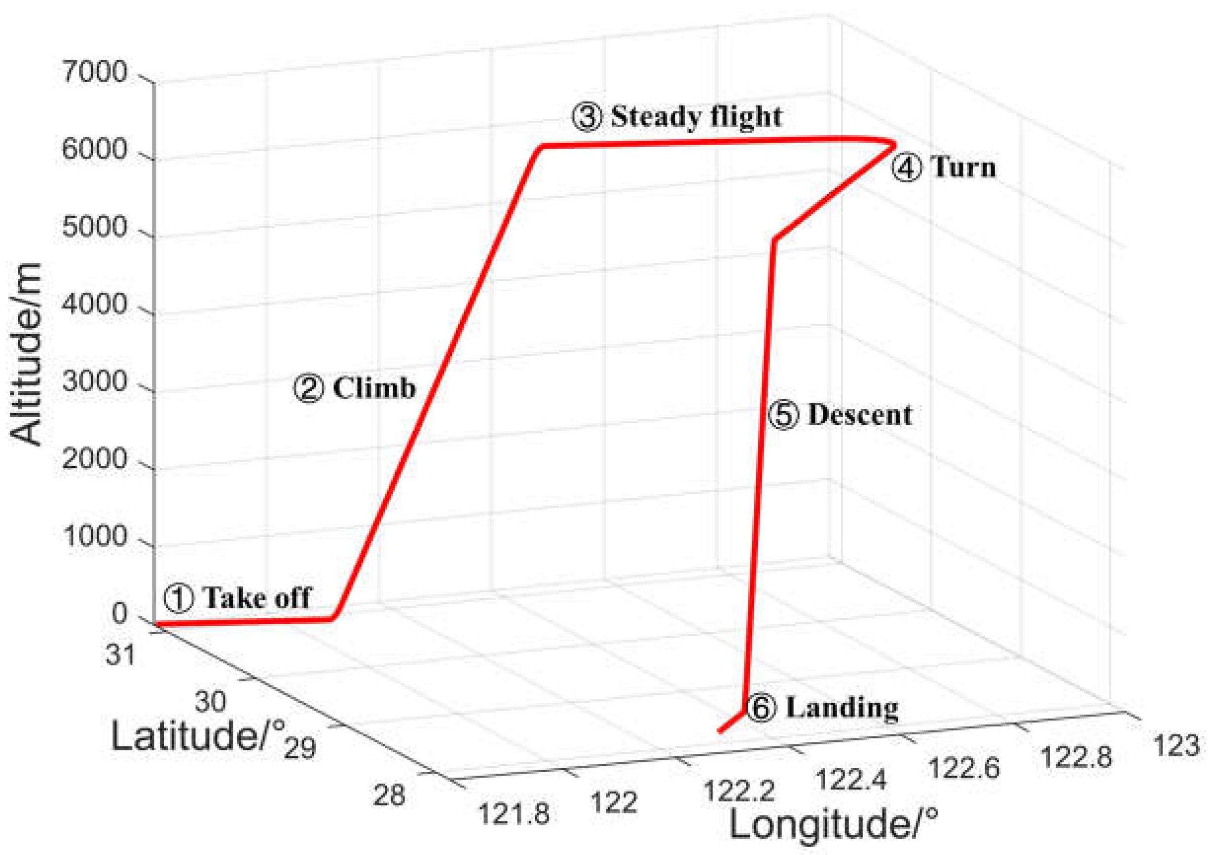
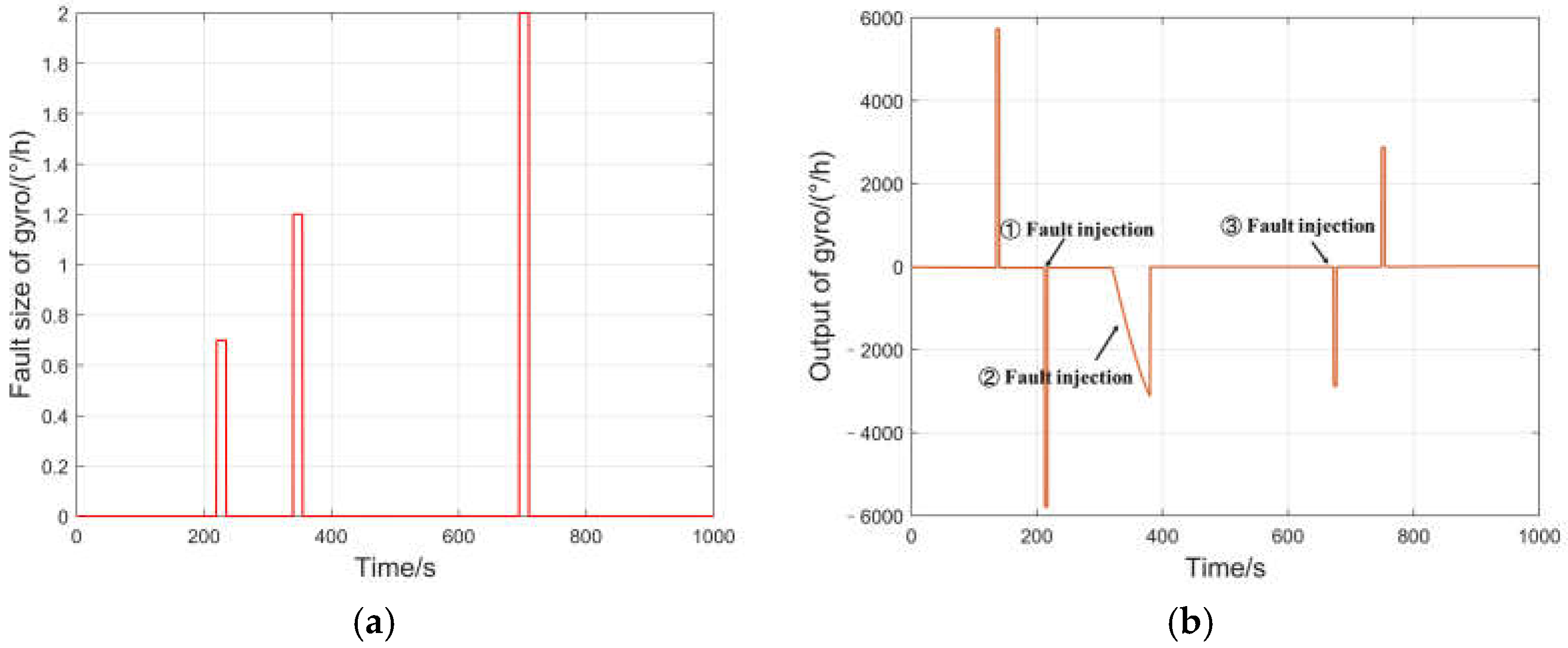
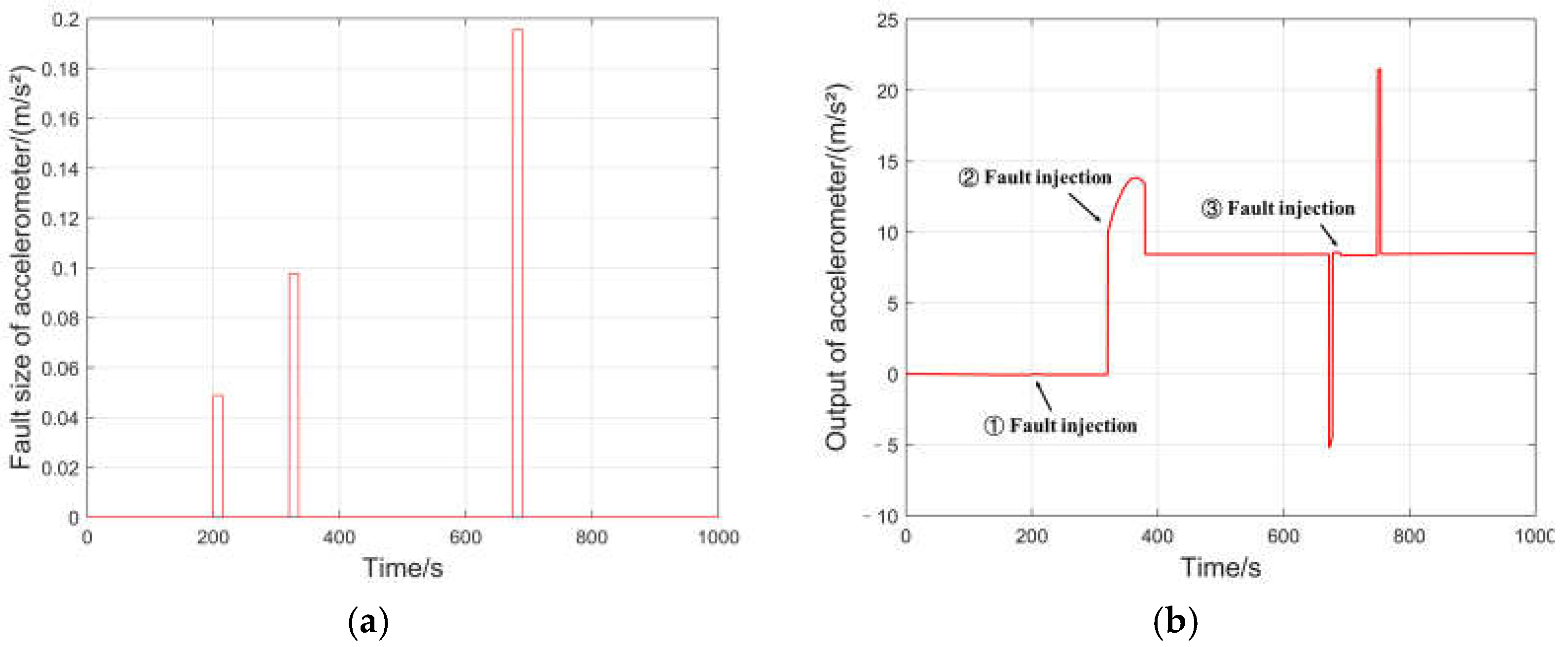
4. Experimental Setup

The PPV-aided SWGLT algorithm is verified by simulation. The aircraft’s flight trajectory is dynamic, taking full account of the aircraft’s maneuverability, comprising five phases: takeoff, climb, steady flight, turn, descent and landing. The fly track simulation output is shown in Figure 3. The initial position is 31.143505° N, 121.803472° E, the altitude is 5 m, and initial heading angle is 135°. The simulation duration is 500 s, and the sampling period is 0.02 s. We use a high-precision inertial sensor model for simulation [27]. With full reference to the performance of existing civil aircraft airborne devices and civil aviation operation standards, the settings of INS and AHRS error characteristics are shown in Table 1 [8].
Injecting faults into the redundant inertial navigation system, the specific conditions are as follows:
Condition 1: the INS1 Y-axis gyro has a fault with a magnitude of 0.5°/h during the take-off phase (220–235 s), a fault with a magnitude of 1°/h during the climb phase (340–355 s), and a fault with a magnitude of 2°/h during the steady flight phase (695–710 s), as shown in Figure 4.
Condition 2: the INS2 X-axis accelerometer has a fault of 0.005 g during the climb phase (200–215 s), has a fault of 0.01 g during the turn phase (320–335 s), and has a fault of 0.02 g during the descent phase (675–690 s), as shown in Figure 5.
Condition 3: INS1 Z-axis gyro has a soft fault rate of 0.02°/h/s during the climb phase (160–210 s), as shown in Figure 6.
We conducted three sets of simulation experiments under three different fault conditions.

5. Results

We perform a comparative analysis of the detection results of the PPV-based SWGLT algorithm proposed in this paper with the traditional GLT method and weighted GLT method without PPV in three different conditions. In the INS/AHRS redundancy system, with the false alarm rate set at 0.01, the traditional fault threshold is T D = χ 0.01 2 ( 6 ) = 16.8 . The sampling window of the SWGLT method is 0.5 s, which means j is 25, and the tolerance ratio factor K is 0.01.
The traditional GLT fault detection results for the INS/AHRS redundance system are shown in Figure 7a and Figure 8a. It can be seen that, because the traditional GLT does not consider the multi-scale error of the subsystem, the detection function cannot accurately reflect the fault characteristics of the redundant system. In the gyroscope fault detection, a large number of false alarms occur because of the large differences in the subsystems. In the accelerometer fault detection, the false alarms are reduced, because of the narrow differences in the subsystems. Meanwhile, traditional GLT can detect major faults (340–355 s and 695–710 s in condition 1 and 320–335 s and 675–690 s in condition 2) more accurately, but when the system has minor faults (220–235 s in condition 1 and 200–215 s in condition 2), there are more missing alarms.
The proposed PPV-aided SWGLT fault detection results for the INS/AHRS redundancy system are shown in Figure 7b and Figure 8b. The fault detection curve of the WGLT is smoother, due to the elimination of pollution caused by the multiscale error noise. Similarly, using the traditional detection threshold based on the false alarm rate, it is not sensitive to the small faults occurring in the system, and fails to detect the small faults occurring in the gyroscope and accelerometer (220–235 s in condition 1 and 200–215 s in condition 2). The proposed PPV-aided SWGLT fault detection threshold is closer to the fault tolerance limit of the redundancy system, and all faults are detected accurately.
The fault detection performances of the traditional GLT method, WGLT, and the SWGLT method proposed in this paper are analyzed statistically, and the results are shown in Table 2. Accuracy represents the proportion of accurate detections of the fault detection method in the total sample data. The SWGLT method proposed in this paper effectively solves the false alarm problem of the traditional methods in the fault detection and missing detection of INS/AHRS redundancy system, and the detection accuracy is improved.
To verify the effectiveness of the proposed algorithm, 50 groups of Monte Carlo simulations were carried out under both condition 1 and condition 2; the simulation results are shown in Table 3.
The statistical analysis shows that the PPV-aided SWGLT proposed in this paper has no false alarm, and the detection accuracy is 88.48% higher than that of the traditional GLT method, and 18.86% higher than that of the WGLT method.
The traditional GLT soft fault detection results for the INS/AHRS redundancy system in condition 3 are shown in Figure 9a. It can be seen that the traditional GLT method cannot deal with the heterogeneity of the sensor, resulting in a large number of false alarms. Meanwhile, when the soft fault occurs, the detection function value of the traditional GLT method does not reach the detection threshold until 193.5 s, and the detection delay reaches 33.5 s.
The proposed PPV-aided SWGLT soft fault detection results for the INS/AHRS redundancy system are shown in Figure 9b. The fault detection curve of WGLT can better reflect the real system error, due to the full consideration of the heterogeneity of redundant systems. Additionally, using the traditional detection threshold based on the false alarm rate, it is not sensitive to the slowly increasing fault amplitude occurring in the system, the detection function value of the traditional GLT method does not reach the detection threshold until 194.3 s, and the detection delay reaches 34.3 s. The proposed PPV-aided SWGLT fault detection threshold is closer to the fault tolerance limit of the redundancy system, as when the soft fault amplitude reaches the tolerance of the system, it can be accurately perceived; the detection delay is 12.9 s.
The soft fault detection performances of the traditional GLT method, WGLT, and the SWGLT method proposed in this paper are analyzed statistically, and the results are shown in Table 4. The SWGLT method proposed in this paper effectively solves the false alarm problem of the traditional method in the fault detection and missing detection of INS/AHRS redundancy system, and the detection accuracy of soft faults is improved.
The statistical analysis shows that the PPV-aided SWGLT proposed in this paper has no false alarm, and the detection accuracy is 3.2 times higher than that of the traditional GLT method, and 32.57% higher than that of the WGLT method; also, the detection delay is 61.49% shorter than that of the traditional GLT method, and 62.39% shorter than that of the WGLT method.
To verify the effectiveness of the proposed algorithm, four groups of simulations were carried out under the different soft faults simulation conditions. The fault sensor and fault injection time are consistent with condition 3, and the simulation results are shown in Table 5.
As the change rate of the soft fault increases gradually, the delay time of the traditional GLT fault detection method and the fault detection method proposed in this paper decreases gradually. However, the traditional GLT method still cannot solve the false alarm problem caused by the heterogeneous sensor. The proposed PPV-aided SWGLT fault detection method can detect the soft fault of the system faster than SWGLT fault detection without PPV.

6. Conclusions

The integrity of the airborne navigation system is a crucial determinant for ensuring flight safety during aviation operations. The integrity of the INS as a navigation reference system is usually guaranteed by two to three sets of redundant configurations, but the traditional direct comparison method has a low fault detection efficiency and is not sensitive to small faults.
Firstly, an INS/AHRS redundant navigation system is constructed in this paper. Secondly, this paper addresses the problem of redundant navigation system fault detection and proposes the PPV-aided SWGLT fault detection method. The fault indication function is constructed by calculating the sequence principal component parity vector, and the adaptive tolerable fault threshold is calculated to enhance the detection ability of minor faults. Finally, by constructing the weighted GLT method, the multi-scale problem of heterogeneous subsystem errors is solved. Thus, the PPV-aided SWGLT proposed in this paper solved the false alarm problem of the traditional GLT method and greatly improved the detection accuracy in the case of minor and soft faults, when compared with GLT and WGLT. The proposed algorithm has a certain theoretical reference value for ensuring the integrity of civil aircraft under RNP operation.

Author Contributions

Conceptualization, Y.D. and J.L.; methodology, Y.D. and J.L.; validation, Y.D., Z.L. and J.L; formal analysis, Y.D. and Y.S.; investigation, Y.D., Q.Z. and Y.S.; data curation, Y.D. and Q.Z.; writing—original draft preparation, Y.D. and Y.S.; writing—review and editing, Y.D. and J.L; visualization, J.L.; supervision, J.L. All authors have read and agreed to the published version of the manuscript.

Funding

This research was funded by the National Key Research and Development Program of China (2022YFB3904300).

Data Availability Statement

Data are contained within the article.

Conflicts of Interest

The authors declare no conflict of interest.

Abbreviations

RNPRequired navigation performance
INSInertial navigation system
GLTGeneralized likelihood ratio
AHRSAttitude and heading reference system
IMAIntegrated modular avionics
FMSFlight management system

References

  1. Joint Planning and Development Office (JPDO). Concept of Operations for the Next Generation Air Transportation System; JPDO: Washington, DC, USA, 2013. [Google Scholar]
  2. SESAR Consortium. The ATM Target of Operations; SESAR Consortium: Brussels Belgium, 2007. [Google Scholar]
  3. International Civil Aviation Organization (ICAO). Doc 9750: 2016–2030 Global Air Navigation Plan; ICAO: Montréal, QC, Canada, 2016. [Google Scholar]
  4. Civil Aviation Administration of China (CAAC). Statistical Bulletin on the Development of Civil Aviation Industry of 2019; CAAC: Beijing, China, 2020. [Google Scholar]
  5. International Civil Aviation Organization (ICAO). Doc 9613: Performance Based Navigation (PBN) Manual; ICAO: Montréal, QC, Canada, 2013. [Google Scholar]
  6. Jiang, W.; Li, Y.; Rizos, C. A multisensor navigation system based on an adaptive fault-tolerant GOF algorithm. IEEE Trans. Intell. Transp. 2017, 18, 103–113. [Google Scholar] [CrossRef]
  7. Aeronautical Radio, Incorporated (ARINC). ARINC 702A: Advanced Flight Management Computer System; ARINC: Annapolis, MD, USA, 2018. [Google Scholar]
  8. Aeronautical Radio, Incorporated (ARINC). ARINC 704: Inertial Reference System; ARINC: Annapolis, MD, USA, 2018. [Google Scholar]
  9. Gilmore, J.P.; McKern, R.A. A redundant strapdown inertial reference unit (SIRU). J. Spacecr. Rocket. 1972, 9, 39–47. [Google Scholar] [CrossRef]
  10. Fazal, Q.; Liaquat, M.; Iftikhar, M. Robust fault tolerant control of an unmanned aerial vehicle in the presence of actuator faults. In Proceedings of the 2016 IEEE/ION Position, Location and Navigation Symposium (PLANS), Savannah, GA, USA, 11–14 April 2016; pp. 757–763. [Google Scholar]
  11. Liu, S.; Lyu, P.; Lai, J.; Yuan, C.; Wang, B. A fault-tolerant attitude estimation method for quadrotors based on analytical redundancy. Aerosp. Sci. Technol. 2019, 93, 105290. [Google Scholar] [CrossRef]
  12. Nobahari, H.; Mohammadkarimi, H. Application of model aided inertial navigation for precise altimetry of Unmanned Aerial Vehicles in ground proximity. Aerosp. Sci. Technol. 2017, 69, 650–658. [Google Scholar] [CrossRef]
  13. Lu, J.; Hu, M.; Yang, Y.; Dai, M. On-Orbit Calibration Method for Redundant IMU Based on Satellite Navigation & Star Sensor Information Fusion. IEEE Sens. J. 2020, 20, 4530–4543. [Google Scholar]
  14. Allerton, D.J.; Jia, H. A review of multi-sensor fusion methodologies for aircraft navigation systems. J. Navig. 2005, 58, 405–417. [Google Scholar] [CrossRef]
  15. Li, D.; Wang, Y.; Wang, J.; Wang, C.; Duan, Y. Recent advances in sensor fault diagnosis: A review. Sens. Actuators A Phys. 2020, 309, 111990. [Google Scholar] [CrossRef]
  16. Zhai, X.; Ren, Y.; Wang, L.; Zhu, T.; He, Y.; Lv, B. A review of redundant inertial navigation technology. In Proceedings of the 2021 International Conference on Computer, Control and Robotics (ICCCR), Shanghai, China, 8–10 January 2021; pp. 272–278. [Google Scholar]
  17. Realpe, M.; Vintimilla, B.; Vlacic, L. Sensor fault detection and diagnosis for autonomous vehicles. In MATEC Web of Conferences; EDP Sciences: Les Ulis, France, 2015; Volume 30, p. 04003. [Google Scholar]
  18. Chen, T.; You, R. A novel fault- tolerant sensor system for sensor drift compensation. Sens. Actuators A 2008, 147, 623–632. [Google Scholar] [CrossRef]
  19. Dai, X.; Lin, Z.; Zhen, S. Fault Tolerant Control in Redundant Inertial Navigation System. Math. Probl. Eng. 2013, 2013, 782617. [Google Scholar] [CrossRef]
  20. Mansouri, M.; Hajji, M.; Trabelsi, M.; Harkat, M.F.; Al-khazraji, A.; Livera, A.; Nounou, H.; Nounou, M. An effective statistical fault detection technique for grid connected photovoltaic systems based on an improved generalized likelihood ratio test. Energy 2018, 159, 842–856. [Google Scholar] [CrossRef]
  21. Du, B.; Shi, Z.; Song, J.; Wang, H.; Han, L. A Fault-Tolerant Data Fusion Method of MEMS Redundant Gyro System Based on Weighted Distributed Kalman Filtering. Micromachines 2019, 10, 278. [Google Scholar] [CrossRef] [PubMed]
  22. Mansouri, M.; Nounou, M.; Nounou, H.; Karim, N. Kernel PCA-based GLRT for nonlinear fault detection of chemical processes. J. Loss Prev. Process Ind. 2016, 40, 334–347. [Google Scholar] [CrossRef]
  23. Harkat, M.F.; Mansouri, M.; Abodayeh, K.; Nounou, M.; Nounou, H. New sensor fault detection and isolation strategy–based interval-valued data. J. Chemom. 2020, 34, e3222. [Google Scholar] [CrossRef]
  24. He, K.P.; Shao, Y.P.; Zhang, L. A Study on Fault Detection Method of Redundant Inertial Navigation System on Micro AUV. Appl. Mech. Mater. 2015, 709, 473–479. [Google Scholar] [CrossRef]
  25. Yang, C.K.; Shim, D.S. FDI using Multiple Parity Vectors for Redundant Inertial Sensors. Eur. J. Control. 2006, 12, 437–449. [Google Scholar] [CrossRef]
  26. Daly, K.C.; Gai, E.; Harrison, J.V. Generalized Likelihood Test for FDI in Redundant Sensor Configurations. J. Guid. Control. Dyn. 2012, 2, 9–17. [Google Scholar] [CrossRef]
  27. Lyu, P.; Wang, B.; Lai, J.; Bai, S. A factor graph optimization method for high-precision IMU based navigation system. IEEE Trans. Instrum. Meas. 2023, 72, 23483881. [Google Scholar] [CrossRef]
Figure 1. Fault detection and isolation (FDI) for a redundant INS with AHRS assistance.
Aerospace 10 01024 g001
Figure 2. PPV-based SWGLT FDI flowchart.
Aerospace 10 01024 g002
Figure 3. Flight simulation trajectory.
Aerospace 10 01024 g003
Figure 4. Fault injection of INS1 Y-axis gyro. (a) Fault size of gyro. (b) Output of gyro.
Aerospace 10 01024 g004
Figure 5. Fault injection of INS2 X-axis accelerometer. (a) Fault size of accelerometer. (b) Output of accelerometer.
Aerospace 10 01024 g005
Figure 6. Soft fault injection of INS1 Z-axis gyro. (a) Soft fault size of gyro. (b) Output of gyro.
Aerospace 10 01024 g006
Figure 7. Comparison results for gyro faults detection. (a) FD function result of GLT. (b) FD function result of WGLT.
Aerospace 10 01024 g007
Figure 8. Comparison results for accelerometer faults detection. (a) FD function result of GLT. (b) FD function result of WGLT.
Aerospace 10 01024 g008
Figure 9. Comparison results for gyro soft faults detection. (a) FD function result of GLT. (b) FD function result of WGLT.
Aerospace 10 01024 g009
Table 1. INS and AHRS error characteristics.
SubsystemsBias Instability of Gyro (°/h)Bias Instability of Acc (m/s2)
INS10.011 × 10−4 g
INS20.011 × 10−4 g
AHRS0.15 × 10−3 g
Table 2. Comparison of fault detection performances.
Statistical ItemsFault Detection Rate (FDR)False Alarm Rate (FAR)Accuracy
Traditional GLT 68.33%67.15%50.59%
WGLT66.66%0%83.33%
PPV-aided SWGLT 99.27%0%99.64%
Table 3. Comparison of fault detection performances in Monte Carlo simulations.
Statistical ItemsFault Detection Rate (FDR)False Alarm Rate (FAR)Accuracy
Traditional GLT 65.40%59.63%52.89%
WGLT67.74%0%83.87%
PPV-aided SWGLT 99.38%0%99.69%
Table 4. Comparison of soft fault detection performances.
Statistical ItemsFault Detection Rate (FDR)False Alarm Rate (FAR)AccuracyDetection Delay
Traditional GLT 33.0%78.32%27.34%33.5 s
WGLT31.4%0%65.70%34.3 s
PPV-aided SWGLT 74.2%0%87.10%12.9 s
Table 5. Comparison of soft fault detection performances.
Statistical ItemsFault Detection Rate (FDR)False Alarm Rate (FAR)AccuracyDetection Delay
Soft fault rate with 0.03°/h/s
Traditional GLT 40.2%76.18%32.01%29.9 s
WGLT34.6%0%67.3%32.7 s
PPV-aided SWGLT 76.4%0%88.2%11.8 s
Soft fault rate with 0.05°/h/s
Traditional GLT 49.4%68.98%40.21%25.3 s
WGLT50.2%0%75.1%24.9 s
PPV-aided SWGLT 83.74%0%91.48%8.13 s
Soft fault rate with 0.1°/h/s
Traditional GLT 85.98%69.22%58.38%7.01 s
WGLT85.1%0%92.55%7.45 s
PPV-aided SWGLT 91.84%0%95.92%4.08 s
Soft fault rate with 0.2°/h/s
Traditional GLT 96.52%69.58%63.47%1.74 s
WGLT96.04%0%98.02%1.98 s
PPV-aided SWGLT 98.48%0%99.24%0.48 s
Disclaimer/Publisher’s Note: The statements, opinions and data contained in all publications are solely those of the individual author(s) and contributor(s) and not of MDPI and/or the editor(s). MDPI and/or the editor(s) disclaim responsibility for any injury to people or property resulting from any ideas, methods, instructions or products referred to in the content.

