Article

Fixed-Time Convergent Guidance Law with Angle Constraint and Autopilot Lag Compensation Using Partial-State Feedback

1
Xi’an Modern Control Technology Research Institute, Xi’an 710111, China
2
School of Computer Science, Xijing University, Xi’an 710123, China
*
Author to whom correspondence should be addressed.
Aerospace 2023, 10(11), 964; https://doi.org/10.3390/aerospace10110964
Submission received: 5 September 2023 / Revised: 24 October 2023 / Accepted: 3 November 2023 / Published: 16 November 2023

Abstract

:
In this paper, by accounting for the angle constraint (AC) and autopilot lag compensation (ALC), a novel fixed-time convergent guidance law is developed based on a fixed-time state observer and bi-limit homogeneous technique. The newly proposed guidance law exhibits three attractive features: (1) unlike existing guidance laws with AC and ALC which can only guarantee asymptotic stability or finite-time stability, the newly proposed guidance scheme can achieve fixed-time stability. Thus, the newly proposed scheme can drive the guidance error to zero within bounded time which is independent of the initial system conditions. (2) To compensate for autopilot lag, existing guidance schemes need the unmeasurable second derivative of the range along line-of-sight (LOS) and second derivative of LOS angle or the derivative of missile’s acceleration. Without using these unmeasurable states, the newly proposed guidance law still can guarantee the fixed-time stability. (3) By using the bi-limit homogeneous technique to construct an integral sliding-mode surface, the proposed scheme eliminates the singular problem without using the commonly-used approximate method in recent fixed-time convergent guidance schemes. Finally, the simulation results demonstrate the effectiveness of the proposed scheme.

1. Introduction

Since the proportional navigation guidance law (PNGL) [1,2,3,4] was first used in engineering, to improve the robustness of conventional PNGL against maneuvering target and system uncertainties, many control theories have been introduced to design guidance law, including the L2 gain method [5], the Lyapunov theory-based nonlinear method [6], the sliding-mode control method [7] and the L1 gain method [8]. However, the PNGL [1,2,3,4] and the guidance laws in [5,6,7,8] are deigned via asymptotic stability theory, which means that guidance error converges to the zero with infinite time. In addition, the only objective of these guidance laws in [1,2,3,4,5,6,7,8] is to obtain a small enough miss distance.
In many terminal guidance cases such as the interception of ballistic targets and kinetic interception, the time of the whole process is quite short, lasting only a few seconds. Moreover, to provide the best damage effect, the missile is required not only to achieve a small enough miss distance, but also obtain a desired impact angle. Thus, it is necessary to design the finite-time convergent guidance law with angle constraint (AC) for these terminal guidance cases. In the past decade, with the development of guidance law design techniques and finite-time control methods [9,10,11,12], the study of finite-time convergent guidance law with AC has become an active research area. Considering finite-time convergence, many guidance schemes have been proposed, including the finite-time Lyapunov theory-based scheme [13], the sliding-mode control scheme [14], the non-smooth control scheme [15], etc. Considering AC, many guidance schemes have been developed, including the optimal guidance scheme [16], the modified PNGL scheme [17], the sliding-mode control scheme [18], etc. Considering both finite-time convergence and AC, some guidance laws also have been proposed. In [19], based on adaptive sliding-mode control, a finite-time convergent guidance law with AC was developed. In [20], by designing a nonsingular terminal sliding-mode (TSM) surface based on nonlinear engagement dynamic, the finite-time convergence and AC were guaranteed. To alleviate the chattering phenomenon of TSM control and achieve finite-time convergence, in [21], a guidance scheme with AC was developed by employing the estimation value of a nonlinear disturbance observer to replace the switch term of TSM control. Although the finite-time convergence and AC have been considered, these guidance laws in [19,20,21] still have two important limitations: (i) the autopilot lag is neglected, and (ii) the finite convergence time of these guidance laws are dependent on the initial system conditions.
For the limitation (i), neglecting autopilot lag can destroy the fast finite-time convergent performance and even reduce the guidance precision, especially against a maneuvering target [22]. Thus, considering autopilot lag compensation (ALC) is necessary. Many guidance laws have considered eliminating the bad effect of autopilot lag by using modern control methods, such as the backstepping control method [23], exact differentiator [24], dynamic the surface control method [25], etc. However, so far, only a few finite-time convergent guidance schemes have considered both effects of AC and ALC. In [26], viewing the missile autopilot as an uncertain system, a finite-time convergent guidance scheme with AC was developed by using step-by-step backstepping. And, at each backstepping step, the virtual control laws were constructed by using the tracking differentiator. However, the method in [26] cannot eliminate steady state error. In [27], based on the integral sliding-mode surface and disturbance observer, a finite-time convergent guidance scheme with AC and ALC was developed, which can drive the guidance errors to zero rather than the neighborhood in [26]. However, to achieve ALC, the guidance law in [26] needs the derivative of the missile’s acceleration, and the guidance law in [27] needs the second derivative of range along LOS and the second derivative of LOS angle. Obviously, in practical missile systems, these states are unmeasurable.
For the limitation (ii), the convergence rate of the finite-time convergent guidance scheme may be very slow while the initial guidance condition increases greatly. Thus, the desired fast convergence performance of finite-time stability may be destroyed. Recently, the fixed-time stability has been introduced to avoid this limitation of finite-time stability [28,29,30]. The fixed-time convergent control not only can drive the system error to zero in a fixed time, but also guarantees that the fixed time is not affected by the initial system conditions. Thus, the limitation (ii) can be eliminated. Recently, the fixed-time convergent guidance schemes with AC have been reported in [31,32,33]. For the stationary target, a fixed-time convergent guidance law with AC was proposed in [31]. In [32,33], for the maneuvering target, based on the disturbance observer and fixed-time sliding-mode surface, the fixed-time convergent guidance schemes with AC were proposed. However, to eliminate the singular problem, a nonlinear function in [32] and a saturation function in [33] were adopted to approximate the singular control term. Thus, the fixed-time convergent guidance laws in [32,33] cannot eliminate steady state error. Moreover, the ALC was not considered in [31,32,33].
Motivated by the problems mentioned above, considering the fixed-time convergence, AC and ALC, a novel guidance law was proposed in this paper. The main contributions of this paper are:
(1)
The fixed-time convergent guidance law with AC and ALC is achieved for the first time.
(2)
The proposed guidance law does not need the unmeasurable states in [26,27] to achieve ALC and still can guarantee the fixed-time stability.
(3)
The proposed guidance law is strictly nonsingular without using the approximate method in [32,33]. Thus, the proposed guidance law can fully eliminate the steady state error in [32,33].
The rest of this paper is organized as follows: in Section 2, the guidance model, design objective and motivations are given. Section 3 provides the main result. In Section 3.1, a state observer is designed and the analysis of fixed-time stability is presented. In the Section 3.2, a fixed-time convergent guidance law is proposed based on integral sliding mode surface and the estimation value of presented state observer. Then, the analysis of fixed-time stability of close-loop system is presented. In Section 4, the simulation is adopted to illustrate the performance of proposed guidance scheme. In Section 5, the conclusion is summarized.

2. Preliminaries

2.1. Model of Missile-Target Engagement

As shown in Figure 1, r and q are the range along LOS and LOS angle, respectively. For missile M and target T, a M and a T denote the normal accelerations, V M and V T denote the velocities, θ M and θ T are the flight path angles. The relative motion can be described as [27]:
r ˙ = V T cos q θ T V M cos q θ M r q ˙ = V T sin q θ T + V M sin q θ M θ ˙ M = a M V M θ ˙ T = a T V T
Differentiating (1) yields:
r ¨ = r q ˙ 2 u r + w r r q ¨ = 2 r ˙ q ˙ u q + w q
where u r and w r denote accelerations of the missile and target along LOS, u q and w q denote the normal accelerations of missile and target relative to LOS.The expressions of these accelerations are given as
u r = V ˙ M cos q θ M + a M sin q θ M w r = V ˙ T cos q θ T + a T sin q θ T u q = V ˙ M sin q θ M + a M cos q θ M w q = V ˙ T sin q θ T + a T cos q θ T
Ref. [27] has pointed out the autopilot can be well approximately described by the first order dynamic with uncertainty. To reduce article length and compare with the guidance scheme given in paper [27], this paper directly adopted the following autopilot model given in [27] as follows:
u ˙ q = 1 τ u q + 1 τ u + d
where τ is the time constant, u is the control input of autopilot, and d denotes the disturbance and unmodeled dynamics.
The constant desired LOS angle is defined as q d . Then the guidance error of LOS angle is
x 1 = q q d
Let x 2 = x ˙ 1 = q ˙ , then we have
x ˙ 2 = 2 r ˙ r x 2 1 r u q + 1 r w q
Let x 3 = x ¨ 1 = q ¨ . Then considering (2)–(4), we have
x ˙ 3 = 2 r ¨ r x 2 3 r ˙ r x 3 + 1 τ r u q 1 τ r u + 1 r w ˙ q 1 τ d
We define the lumped disturbance as
Δ = w ˙ q 1 τ d
Then, according to (7) and (8), we have
x ˙ 1 = x 2 x ˙ 2 = x 3 x ˙ 3 = 2 r ¨ / r x 2 3 r ˙ / r x 3 + 1 / τ r u q 1 / τ r u + 1 / r Δ
The following assumptions should be satisfied:
Assumption 1.
The states q, q ˙ , r, r ˙ and u q are measurable.
Assumption 2
([27]). The lumped disturbance Δ is bounded as Δ Δ max , where Δ max is a positive constant.
Assumption 3.
The velocities V M and V T are bounded as V M V M max and V T V T max , respectively, where V M max and V T max are positive constants.
Assumption 4
([27]). The time derivatives of target accelerations w q and w r defined in (3) are assumed to be bounded and satisfy w ˙ q w q max and w ˙ r w r max , where w q max and w r max are positive constants.
Remark 1.
As in the assumption, the proposed guidance law needs the seeker which can measure the distance to the target, such as the radar seeker.
Remark 2.
In this paper, we only consider the terminal guidance cases, thus the engine thrust of the missile is zero. The derivative of missile velocity can be described as V ˙ M = 1 2 C x α , β , t V M 2 S M m M + a g + Δ f , where C x α , β , t < 0 is the air resistance coefficient, ℓ is the air density, S M is the reference area, m M is the missile mass and a g is the component of the gravitational acceleration g in velocity direction. Δ f denotes the wind interference and other disturbance. Since Δ f g and a g g , we have V ˙ M 1 2 C x α , β , t V M 2 S M m M + 2 g . Then, we know that V ˙ M 0 if V M 2 g / C x α , β , t ρ S M m M . Thus, the assumption that V M is bounded is reasonable. Moreover, according to the target characteristics, we can know that the target velocity V T is bounded, such as the velocity of ordinary cruise missile is bounded by 600 m / s and the velocity of large ships is not more than 35 m / s . In all, the Assumption 3 is reasonable.

2.2. Design Objective and Motivation

As stated in the Introduction section, the design objective and motivation are:
(1)
The first objective is to design the command of autopilot u in such a way that the guidance errors x 1 = x 2 = 0 are guaranteed in fixed-time under the disturbance Δ . And, the convergence time is always bounded by a fixed constant. Compared with existing results, the fixed-time convergent guidance scheme with AC and ALC is achieved for the first time.
(2)
The second objective is to avoid using the unmeasurable states to compensate the autopilot lag (such as the guidance law in [26] needs the derivative of missile’s acceleration, the guidance law in [27] needs the second derivatives of the range along LOS and the LOS angle).
(3)
The third objective is to not only guarantee the fixed-time convergence, but also to strictly guarantee the guidance error converges to zero rather than a neighborhood of zero such as in the existing fixed-time convergent guidance law in [32,33]. Thus, the proposed guidance law should avoid using the approximate method in [32,33].

2.3. Fundamental Facts

We consider the following dynamic system
y ˙ = F y , D
where y R n is the system state vector and D R n is the uncertain vector. Then, the definitions of conventional finite-time and fixed-time stability are reviewed as follows:
Definition 1
([34] (Finite-time stability)). For the system (10), the finite-time stability of origin y 0 is achieved if t T m y 0 : y = 0 . The convergence time T m y 0 is finite.
Remark 3.
From Definition 1, we know that the finite-time stability can achieve finite convergence time T m y 0 . However, T m y 0 is generally an unbounded function with respect to initial system condition y 0 . To eliminate the effect of initial system condition, the fixed-time stability is given as follows:
Definition 2
([34] (Fixed-time stability)). For the system (10), the fixed-time stability can be guaranteed if t T m y 0 : y = 0 , T m y 0 T max , where T max is a constant and is independent of initial system condition y 0 .
In this paper, for the state ϖ R and constant > 0 , the function ϖ is defined as
ϖ = ϖ sign ϖ
Before designing the fixed-time convergent guidance law, some useful lemmas are given below for convenience:
Lemma 1
([35]). Consider an uncertain system:
h ˙ 0 = λ ¯ 1 h 0 1 / 2 + ψ ¯ h 0 3 / 2 + h 1 h ˙ 1 = λ ¯ 2 1 2 h 0 0 + 2 ψ ¯ h 0 + 3 2 ψ ¯ 2 h 0 2 d 0 t
where ψ ¯ > 0 and h j j = 0 , 1 are the system states. The uncertainty d 0 t is bounded as d 0 t d ¯ . If λ ¯ 1 and λ ¯ 2 satisfied 0 < λ ¯ 1 2 d ¯ , λ ¯ 2 > λ ¯ 1 2 / 4 + 4 d ¯ 2 / λ ¯ 1 2 , λ ¯ 1 > 2 d ¯ and λ ¯ 2 > 2 d ¯ . Then, for ζ h = h ¯ T H h h ¯ , where h ¯ = h 0 1 / 2 + ψ ¯ h 0 3 / 2 , h 1 T and H h is a positive definite matrix, we have
ζ ˙ h ϑ ¯ 1 H h , τ ζ h 1 2 ϑ ¯ 2 H h , τ ψ ¯ h 0 1 2 ζ h
where τ > 0 and ϑ ¯ j H h , τ > 0 j = 1 , 2 . And, the fixed-time stability of states h 0 = 0 and h 1 = 0 can be guaranteed.
The proof of Lemma 1 can be referred to the Appendices A and B of [35].
Lemma 2
([36]). Consider a certain system:
x ˙ 1 = x 2 x ˙ 2 = x 3 x ˙ n = i = 1 n k i x i i + x i + x i ¯ i
where x i R i = 1 , 2 , , n are the system states. The positive constants k i > 0 i = 1 , 2 , , n are selected to ensure that the n-order polynomials h n + i = 1 n 1 k i + 1 h i + k 1 and h n + 3 i = 1 n 1 k i + 1 h i + 3 k 1 are Hurwitz. The parameters i and ¯ i i = 1 , 2 , , n are selected as n j = / j + 1 j and ¯ n j = 2 / j j 1 j = 0 , 1 , , n 1 , where the parameter ∂ is selected in the interval ε , 1 with ε n 2 / n 1 , 1 . Then for any initial condition x i 0 R i = 1 , 2 , , n , the fixed-time stability can be achieved, i.e.,
x i = 0 , i f t t e
t x T x
where T x is a constant.
The proof of Lemma 2 can be referred to the proof of Theorem 1 in [36].
Lemma 3
([30]). For any ω i 0 i = 1 , , n , the following conditions can be satisfied
i = 1 n ω i β i = 1 n ω i β , f o r 0 < β 1
i = 1 n ω i β n 1 β i = 1 n ω i β , f o r β 1
The proof of Lemma 3 can be referred to in [30].

3. Main Result

3.1. Fixed-Time Convergent State Observer

For the unmeasurable states x 3 and r ¨ , two fixed-time convergent observers are developed in this section. The fixed-time convergent state observer for x 3 is designed as
h ˙ 11 = μ 11 h ¯ 11 1 / 2 + μ 12 h ¯ 11 3 / 2 + h 12 2 r ˙ x 2 u q h ˙ 12 = μ 13 1 2 h ¯ 11 0 + 2 μ 12 h ¯ 11 + 3 2 μ 12 2 h ¯ 11 2 h ¯ 11 = h 11 r x 2 + 0 t r ˙ x 2 d υ x ^ 3 = 2 r ˙ x 2 u q + h 12 / r
The fixed-time convergent state observer for r ¨ is designed as
h ˙ 21 = μ 21 h ¯ 21 1 / 2 + μ 22 h ¯ 21 3 / 2 + h 22 + r q ˙ 2 u r h ˙ 22 = μ 23 1 2 h ¯ 21 0 + 2 μ 22 h ¯ 21 + 3 2 μ 22 2 h ¯ 21 2 h ¯ 21 = h 21 r ˙ ¨ ^ r = r q ˙ 2 u r + h 22
In the observers (19) and (20), x ^ 3 and r ¨ ^ denote the estimations of the unmeasurable states x 3 and r ¨ , respectively. h 11 and h 21 are the auxiliary states. h 12 is the estimation of disturbance w q . h 22 is the estimation of disturbance w r . For m = 1 , 2 , μ m 2 > 0 , μ m 1 and μ m 3 are in the following set:
Ω = μ m 1 , μ m 3 R 2 0 < μ m 1 2 D m max , μ m 3 > μ m 1 2 4 + 4 D m max 2 μ m 1 2 μ m 1 , μ m 3 R 2 μ m 1 > 2 D m max , μ j 3 > 2 D m max
where D 1 max = w q max and D 2 max = w r max . w q max and w r max have been defined in Assumption 4.
Then, the stability analysis of proposed observer is given by following Theorem 1:
Theorem 1.
Taking system (9) into consideration, the fixed-time convergent state observers are constructed as (19) and (20). Define the state estimation errors as x ¯ 3 = x 3 x ^ 3 and r ¨ ¯ = r ¨ r ¨ ^ , then state estimation errors can converge to zero in fixed time for any initial condition x i 0 R i = 1 , 2 , 3 and r 0 R .
The proof of Theorem 1 is provided in Appendix A.

3.2. Fixed-Time Convergent Guidance Law

By using the estimation value x ^ 3 given in fixed-time convergent state observer (19), an integral sliding-mode surface is developed as:
s = x ^ 3 + 0 t i = 1 2 c i x i λ i + x i + x i λ ¯ i + c 3 x ^ 3 λ 3 + x ^ 3 + x ^ 3 λ ¯ 3 d υ
where the positive constants c i i = 1 , 2 , 3 are selected to ensure that the n-order polynomials h 3 + i = 1 2 c i + 1 h i + c 1 and h 3 + 3 i = 1 2 c i + 1 h i + 3 c 1 are Hurwitz. The parameters λ i and λ ¯ i i = 1 , 2 , 3 are selected as λ 3 j = λ 0 / j + 1 j λ 0 and λ ¯ 3 j = 2 λ 0 / j λ 0 j 1 j = 0 , 1 , , 2 , where the parameter λ 0 is selected in the interval σ , 1 with σ 1 / 2 , 1 .
Based on the sliding-mode surface s designed in (22) and the estimation values x ^ 3 and r ¨ ^ given by fixed-time convergent state observer (19), the fixed-time convergent guidance law is designed as
u = τ r 2 r ¨ ^ / r x 2 3 r ˙ / r x ^ 3 + 1 / τ r u q + τ r η s ρ + s 2 ρ + 1 / r Δ max s 0 + τ r i = 1 2 c i x i λ i + x i + x i λ ¯ i + τ r c 3 x ^ 3 λ 3 + x ^ 3 + x ^ 3 λ ¯ 3
where Δ max has been defined in Assumption 2. ρ and η are positive constants and ρ satisfies 0 < ρ < 1 .
Calculating the time derivative of s, we have
s ˙ = x ^ ˙ 3 + i = 1 2 c i x i λ i + x i + x i λ ¯ i + c 3 x ^ 3 λ 3 + x ^ 3 + x ^ 3 λ ¯ 3
Consider the state estimation error x ¯ 3 = x 3 x ^ 3 defined in Theorem 1, then we have
s ˙ = x ˙ 3 x ¯ ˙ 3 + i = 1 2 c i x i λ i + x i + x i λ ¯ i + c 3 x ^ 3 λ 3 + x ^ 3 + x ^ 3 λ ¯ 3
Substituting the expressions of x ˙ 3 in (9) into (25) gives
s ˙ = 2 r ¨ / r x 2 3 r ˙ / r x 3 + 1 / τ r u q 1 / τ r u + 1 / r Δ x ¯ ˙ 3 + i = 1 2 c i x i λ i + x i + x i λ ¯ i + c 3 x ^ 3 λ 3 + x ^ 3 + x ^ 3 λ ¯ 3
Substituting the proposed guidance law (23) into (26) and considering r ¨ ¯ = r ¨ r ¨ ^ yield
s ˙ = 2 r ¨ ¯ / r x 2 3 r ˙ / r x ¯ 3 1 / r Δ max s 0 Δ η s ρ + s 2 ρ x ¯ ˙ 3
Substituting the proposed guidance law (23) into the expression of x ˙ 3 in (9) yields
x ˙ 3 = 2 r ¨ ¯ / r x 2 3 r ˙ / r x ¯ 3 η s ρ + s 2 ρ 1 / r Δ max s 0 Δ i = 1 2 c i x i λ i + x i + x i λ ¯ i c 3 x ^ 3 λ 3 + x ^ 3 + x ^ 3 λ ¯ 3
Then, stability analysis of the proposed guidance law is given by following Theorem 2:
Theorem 2.
Considering the system (9) adopts the fixed-time convergent guidance law (23), then s = 0 can be guaranteed in fixed time. And the system states x i i = 1 , 2 , 3 can converge to zero in a fixed time for any initial condition x i 0 R i = 1 , 2 , 3 and r 0 R .
The proof of Theorem 2 is provided in Appendix B.
Remark 4.
By using the bi-limit homogeneous technique to construct the integral sliding-mode surface (22), the derivative of sliding-mode surface (24) does not contain any singular term. Then, the guidance law (23) does not contain any singular term. Thus, the singular problem can be eliminated without using the commonly-used approximate method in recent fixed-time convergent guidance schemes [32,33].
Remark 5.
For the state observers (19) and (20), the fixed convergence times T h 1 and T h 2 of estimation errors are determined by the parameters μ 11 , μ 13 , μ 21 and μ 23 . And the corresponding relations between T h i i = 1 , 2 and μ i j i = 1 , 2 ; j = 1 , 3 can be found in Section IV of [35]. The parameters η and ρ determine the convergence time of sliding-mode surface, the corresponding relations between the convergence time of sliding-mode surface and parameters η and ρ can be found in (A61). For the bi-limit homogeneous technique, it is difficult to provide a clear relation expression between the parameters c i i = 1 , 2 , 3 , λ i i = 1 , 2 , 3 , λ ¯ i i = 1 , 2 , 3 and convergence times on the sliding-mode surface at present. Fortunately, in engineering, by using the trial-and-error method, we can obtain the relationship between the parameters and convergence times on the sliding-mode surface. And, since the fixed convergence time is not affected by the initial system conditions, the relationship is always true in different cases.
Remark 6.
From the Theorem 2, we can know that the proposed guidance law is the fixed-time convergent and considers AC and ALC. Compared with existing fixed-time-convergent guidance laws, this is the fist time that the AC and ALC are simultaneously considered. From the expression of the proposed guidance law given in (26), we can know that the proposed scheme does not need the unmeasurable states in [26,27]. Moreover, from (41), we can know that the proposed guidance law does not contain any singular term and does not need to use the approximate method in [32,33].

4. Simulation Results

The initial range along LOS is r 0 = 3000 m . The initial LOS angle is q 0 = 5 . The initial missile velocity and flight-path angle are V M 0 = 800 m / s and θ M 0 = 5 , respectively. The initial target velocity and flight-path angle are V T 0 = 350 m / s and θ t 0 = 15 , respectively. The gravitational acceleration is g = 9.8 m / s 2 . The autopilot constant is selected as τ = 0.5 . The missile and target velocities are time-varying and defined as V ˙ M = 9 + 3 sin t and V ˙ T = 8 + 2 cos t , respectively. In addition, the missile acceleration command is bounded by 500 m / s 2 . The target acceleration is chosen as a T = 20 + 20 sin t m / s 2 . The uncertainty of autopilot is chosen as d = 30 + 30 sin t m /s 2 .
For the comparison, the following four guidance laws are considered in this section:
(1) Finite-time guidance law with AC (FGLA): if we only consider the angle constraint and do not consider the autopilot lag, according to [27], the FGLA can be designed as
u = 2 r ˙ r x 2 + r i = 1 2 k 1 i x i α 1 i + η 1 sign s 1
s 1 = x 2 + 0 t i = 1 2 k 1 i x i α 1 i d υ
where the guidance parameters are selected as k 11 = 2 , k 12 = 3 , α 11 = 6 / 11 , α 12 = 2 / 3 and η 1 = 150 .
(2) Finite-time guidance law with AC and ALC (FGLAA): if we consider both the angle constraint and the autopilot lag, according to [27], the FGLAA can be designed as
u = 2 τ r ¨ x 2 3 τ r ˙ x 3 + u q + τ r i = 1 3 k 2 i x i α 2 i + τ η 2 sign s 2 + d ^
s 2 = x 3 x 3 0 + 0 t i = 1 3 k 2 i x i α 2 i d υ
z ˙ = 2 r ¨ / r x 2 3 r ˙ / r x 3 + 1 / τ r u q 1 / τ r u + 1 / r d ^ d ^ = χ 2 x 3 z
where the guidance parameters are selected as k 21 = 0.4 , k 22 = 1 , k 23 = 1 , α 21 = 3.5 / 11 , α 22 = 1 / 2 , α 23 = 4 / 5 , η 2 = 150 . The parameter of observer (33) is chosen as χ 2 = 2000 .
(3) Proposed fixed-time convergent guidance law with AC and ALC using full states feedback (proposed FGLAA (full state)): if we assume that the states x 3 and r ¨ can be measured, the proposed guidance law (23) can be revised by using the real states x 3 and r ¨ to replace the estimate states x ^ 3 and r ¨ ^ in (23) as
u = τ r 2 r ¨ / r x 2 3 r ˙ / r x 3 + 1 / τ r u q + τ r η s ρ + s 2 ρ + 1 / r Δ max s 0 τ r i = 1 3 c i x i λ i + x i + x i λ ¯ i
where the guidance parameters are selected as c 1 = 1 , c 2 = 1.65 , c 3 = 1 , λ 0 = 0.85 , η = 0.6 , ρ = 0.7 and Δ max = 130 .
(4) Proposed fixed-time convergent guidance law with AC and ALC using partial states feedback (proposed FGLAA (partial state)): if we consider the states x 3 and r ¨ are unmeasurable, the proposed FGLAA (full state) is given in (23). The guidance parameters are selected as c 1 = 1 , c 2 = 1.65 , c 3 = 1 , λ 0 = 0.85 , η = 0.6 , ρ = 0.7 and Δ max = 130 . The parameters of observers are chosen as μ 11 = 18 , μ 12 = 3 , μ 13 = 120 , μ 21 = 8 , μ 22 = 20 and μ 23 = 20 .
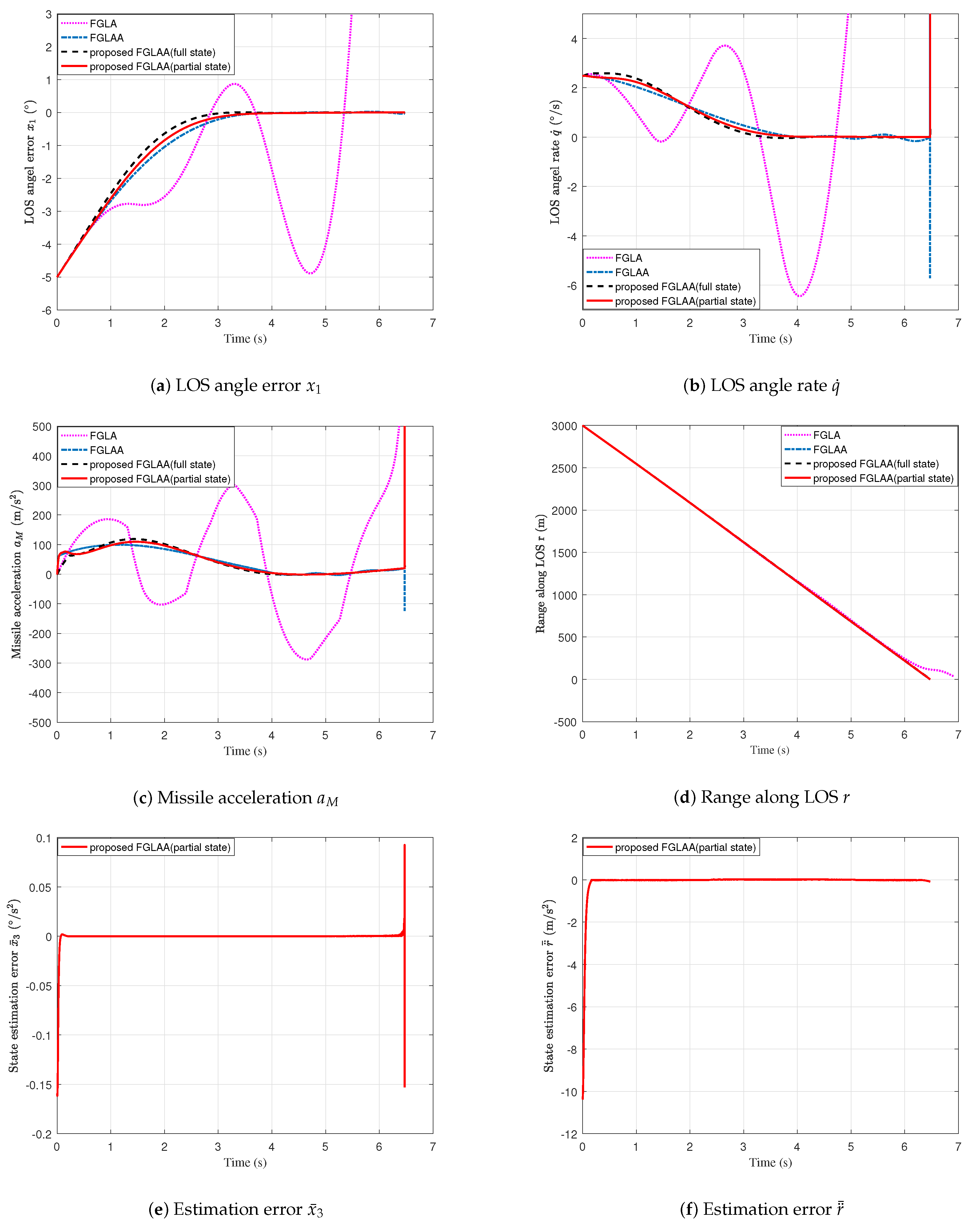
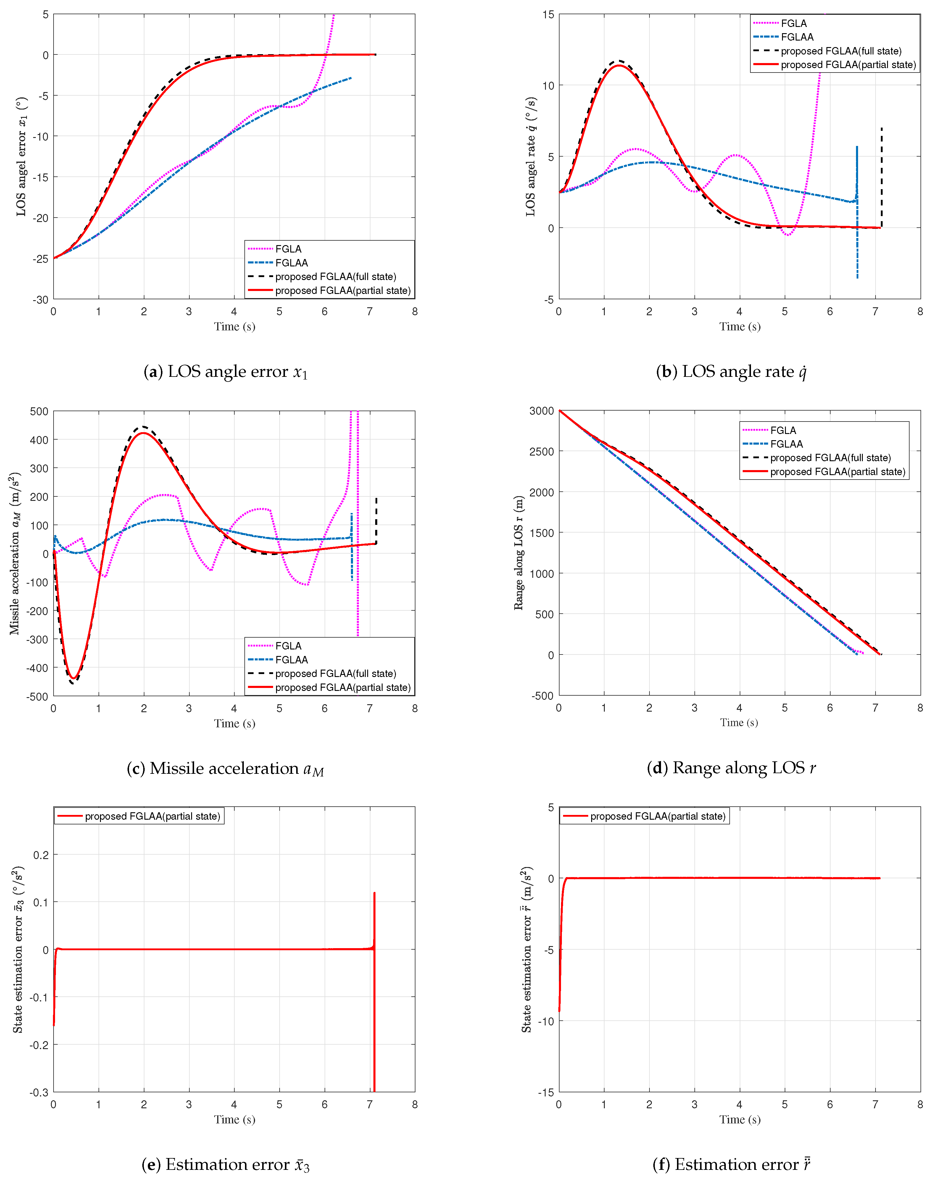
Note: to briefly state the simulation result, in the following simulation Figures, FGLA, FGLAA, proposed FGLAA (full state) and proposed FGLAA (partial state) denote the finite-time guidance law with angle constraint (29), the finite-time guidance law with angle constraint and autopilot lag (31), the proposed fixed-time convergent guidance law with angle constraint and autopilot lag using full states feedback (34) and the proposed fixed-time convergent guidance law with angle constraint and autopilot lag using partial states feedback (23), respectively.
We consider the following two kinds of initial system conditions which are chosen from the small value to the large value:
Case 1 (small initial system conditions): in this case, the desired LOS angle is chosen as q d = 10 . Thus, the initial LOS angle error is x 1 0 = 5 . Figure 2a–f show the simulation results for Case 1. The miss distances are given in Table 1. From Figure 2a,b, for the missile with FGLA, LOS angle error x 1 and LOS angle rate q ˙ not only cannot converge to zero, but also are oscillatory with a large amplitude. Meanwhile, under the FGLAA, the proposed FGLAA (full state) or the proposed FGLAA (partial state), the LOS angle error x 1 and LOS angle rate q ˙ all can achieve a similar fast convergence rate and high convergence precision. As mentioned before, the reason is that the FGLA does not consider the bad influence of autopilot lag, and the autopilot lag can greatly degrade the performance of FGLA. Table 1 also shows that FGLA only can guarantee the final miss distance is 7.67 m without considering the autopilot lag, which implies that the FGLA cannot accomplish the interception mission. From Figure 2a,b, compared with the other guidance laws with full states feedback, we also know that the proposed FGLAA (partial state) can achieve a similar excellent guidance performance even with partial states feedback. From Figure 2e,f, we know that the proposed fixed-time convergent state observers can guarantee the state estimation errors x ¯ 3 and r ¨ ¯ converge to zero.
Case 2 (large initial system conditions): compared with Case 1, the desired LOS angle is increased to q d = 30 . Then, the initial LOS angle error is x 1 0 = 25 . Thus, the initial system state x 1 0 in Case 2 is much larger than that in Case 1 (five times as much as in Case 1). Figure 3a–f show the simulation results for Case 2. The miss distances are given in Table 1. Figure 3a,b show that the convergence performance of FGLAA is greatly affected by the increase of initial system state. As stated in the Introduction section, this is because the FGLAA is finite-time stable, and the convergence time of FGLAA is dependent on the initial system conditions. And, like the results in Case 1, Figure 3a,b show that the proposed FGLAA (full state) and FGLAA (partial state) still can achieve a fast convergence rate. Moreover, only using partial states to obtain feedback, the performance of proposed FGLAA (partial state) is very similar to that of FGLAA (full state). Figure 3e,f show that the proposed fixed-time convergent state observers can guarantee the estimation errors converge to zero with a similar fast convergence rate like Case 1. From Table 1, compared with the results of Case 1, it can be observed that the final miss distance of FGLAA is increase to 2.55 m, and the miss distance of the proposed guidance methods are still less than 0.01 m.
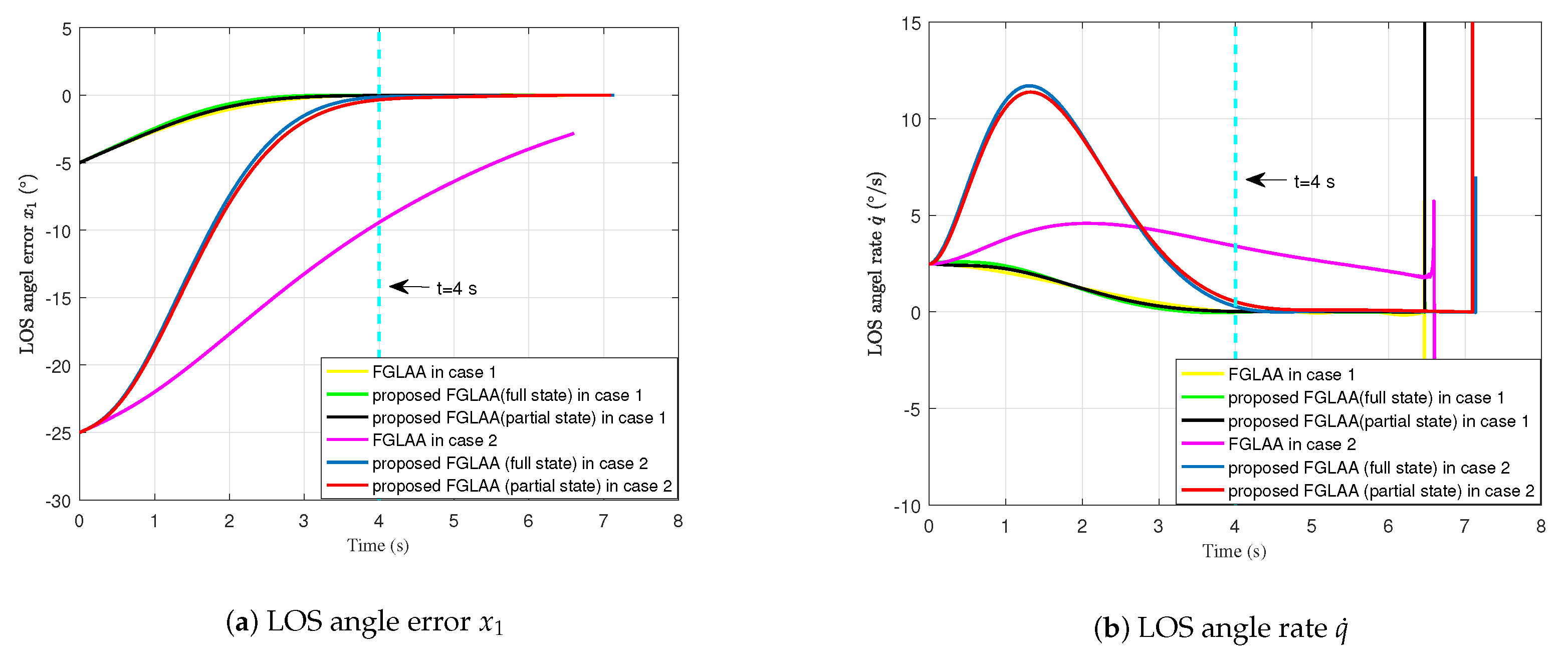
For convenience, the convergence performance of FGLAA, proposed FGLAA (full state) and FGLAA (partial state) in the above two cases are plotted in Figure 4. Figure 4 shows that the convergence rate of FGLAA is lowed greatly with the increase of initial system state. And the proposed FGLAA (full state) and FGLAA (partial state) are not affected by the different initial system conditions. The proposed guidance methods can guarantee the LOS angle error x 1 and LOS angle rate q ˙ converge to zero in 4 s for the two cases. In addition, only using partial states, the proposed FGLAA (partial state) can achieve a very similar convergence performance like FGLAA (full state).

5. Conclusions

In this paper, a novel fixed-time convergent guidance law with AC and ALC was proposed based on a fixed-time state observer and the bi-limit homogeneous technique. The main contributions presented here are as follows: (1) considering AC and ALC, the fixed-time stability of a guidance system is achieved for the first time. (2) Without using the unmeasurable second derivative of the range along LOS and second derivative of LOS angle, the proposed guidance law can still guarantee the fixed-time stability of the guidance system. Finally, mathematical simulation results demonstrated the theoretical analysis of the proposed guidance law. In this paper, we considered the autopilot lag as a one-order subsystem, and the high-order dynamics were considered as uncertainties. In future work, we will consider more complex case which the autopilot lag is a high-order subsystem. By considering these high-order dynamics, we can achieve better transient performance. The controller discretization is important for the actual guidance system. In the future, we will discretize the guidance law of this paper and prove the fixed-time stability of the new guidance law. Moreover, the result was not illustrated by experiments; in later research, with the improvement of our experimental conditions, we will also carry out an experimental method, and compare the theoretical results with the experimental results.

Author Contributions

Conceptualization, C.X. and Y.W.; Methodology, C.X.; Software, Z.N.; Validation, S.L. and F.D.; Formal Analysis, C.X.; Investigation, S.L.; Resources, C.X., Y.W. and Z.N.; Data Curation, C.X.; Writing—Original Draft Preparation, C.X., Y.W. and Z.N.; Writing—Review & Editing, C.X., Y.W., Z.N., S.L. and F.D.; Visualization, C.X.; Supervision, C.X.; Project Administration, C.X.; Funding Acquisition, C.X. All authors have read and agreed to the published version of the manuscript.

Funding

This work is supported by The shannxi Association for Science and Technology Youth Talent Support Program (No. 20230239), Young Talent Fund of Association for Science and Technology in Xi’an (No. 095920221378) and the Scientific Research Fund for High-Level Talents of Xijing University (XJ22B01).

Data Availability Statement

All data generated or analysed during this study are included in this published article.

Conflicts of Interest

The authors declare no conflict of interest.

Appendix A. Proof of Theorem 1

Define four auxiliary estimation errors h ¯ m p m = 1 , 2 ; p = 1 , 2 as
h ¯ 11 = h 11 r x 2 + 0 t r ˙ x 2 d υ h ¯ 12 = h 12 w q
h ¯ 21 = h 21 r ˙ h ¯ 22 = h 22 w r
Differentiating the auxiliary estimation error h ¯ m p m = 1 , 2 ; p = 1 , 2 gives
h ¯ ˙ 11 = h ˙ 11 r x ˙ 2 h ¯ ˙ 12 = h ˙ 12 w ˙ q
h ¯ ˙ 21 = h ˙ 21 r ¨ h ¯ ˙ 22 = h ˙ 22 w ˙ r
Substituting the expressions of h ˙ m p m = 1 , 2 ; p = 1 , 2 in (19) and (20) into (A3), we have
h ¯ ˙ 11 = μ 11 h ¯ 11 1 / 2 + μ 12 h ¯ 11 3 / 2 + h 12 2 r ˙ x 2 u q r x ˙ 2 h ¯ ˙ 12 = μ 13 1 2 h ¯ 11 0 + 2 μ 12 h ¯ 11 + 3 2 μ 12 2 h ¯ 11 2 w ˙ q
h ¯ ˙ 21 = μ 21 h ¯ 21 1 / 2 + μ 22 h ¯ 21 3 / 2 + h 22 + r q ˙ 2 u r r ¨ h ¯ ˙ 22 = μ 23 1 2 h ¯ 21 0 + 2 μ 22 h ¯ 21 + 3 2 μ 22 2 h ¯ 21 2 w ˙ r
Substituting the expression of x ˙ 2 in (6) into (A5) and the expression of r ¨ in (2) into (A6) give
h ¯ ˙ 11 = μ 11 h ¯ 11 1 / 2 + μ 12 h ¯ 11 3 / 2 + h 12 2 r ˙ x 2 u q 2 r ˙ x 2 u q + w q h ¯ ˙ 12 = μ 13 1 2 h ¯ 11 0 + 2 μ 12 h ¯ 11 + 3 2 μ 12 2 h ¯ 11 2 w ˙ q
h ¯ ˙ 21 = μ 21 h ¯ 21 1 / 2 + μ 22 h ¯ 21 3 / 2 + h 22 + r q ˙ 2 u r r q ˙ 2 u r + w r h ¯ ˙ 22 = μ 23 1 2 h ¯ 21 0 + 2 μ 22 h ¯ 21 + 3 2 μ 22 2 h ¯ 21 2 w ˙ r
Then, we obtain
h ¯ ˙ 11 = μ 11 h ¯ 11 1 / 2 + μ 12 h ¯ 11 3 / 2 + h 12 w q h ¯ ˙ 12 = μ 13 1 2 h ¯ 11 0 + 2 μ 12 h ¯ 11 + 3 2 μ 12 2 h ¯ 11 2 w ˙ q
h ¯ ˙ 21 = μ 21 h ¯ 21 1 / 2 + μ 22 h ¯ 21 3 / 2 + h 22 w r h ¯ ˙ 22 = μ 23 1 2 h ¯ 21 0 + 2 μ 22 h ¯ 21 + 3 2 μ 22 2 h ¯ 21 2 w ˙ r
Combining h ¯ 12 = h 12 w q defined in (A1) and h ¯ 22 = h 22 w r defined in (A2), then (A9) and (A10) can be rewritten as
h ¯ ˙ 11 = μ 11 h ¯ 11 1 / 2 + μ 12 h ¯ 11 3 / 2 + h ¯ 12 h ¯ ˙ 12 = μ 13 1 2 h ¯ 11 0 + 2 μ 12 h ¯ 11 + 3 2 μ 12 2 h ¯ 11 2 w ˙ q
h ¯ ˙ 21 = μ 21 h ¯ 21 1 / 2 + μ 22 h ¯ 21 3 / 2 + h ¯ 22 h ¯ ˙ 22 = μ 23 1 2 h ¯ 21 0 + 2 μ 22 h ¯ 21 + 3 2 μ 22 2 h ¯ 21 2 w ˙ r
According to Lemma 1, for m = 1 , 2 , if μ m 2 > 0 , μ m 1 and μ m 3 are chosen in set (21) and Assumption 4 is valid, then the estimation errors h ¯ m 1 m = 1 , 2 are bounded from the initial time and will converge to zero in fixed time:
h ¯ 12 = h 12 w q = 0 , i f t > T h 1
h ¯ 22 = h 22 w r = 0 , i f t > T h 2
where T h p p = 1 , 2 are positive constants and are not affected by the initial system conditions.
Substituting the expressions of x ^ 3 in (19), x ˙ 2 in (6), r ¨ ^ in (20) and r ¨ in (2) into the state estimation error x ¯ 3 = x 3 x ^ 3 and r ¨ ¯ = r ¨ r ¨ ^ yields
x ¯ 3 = 2 r ˙ x 2 u q + w q / r 2 r ˙ x 2 u q + h 12 / r = h ¯ 12 / r
r ¨ ¯ = r q ˙ 2 u r + w r r q ˙ 2 u r + h 22 = h ¯ 22
Then, combining (A13)–(A16), we have
x ¯ 3 = 0 , i f t T h 1
r ¨ ¯ = 0 , i f t T h 2
The proof is finished.

Appendix B. Proof of Theorem 2

Construct a Lyapunov function V 1 as
V 1 = 1 2 s 2
Calculating the time derivative of V 1 and considering (27) yield
V ˙ 1 = s s ˙ = s 2 r ¨ ¯ / r x 2 3 r ˙ / r x ¯ 3 1 / r Δ max s 0 Δ s η s ρ + s 2 ρ + x ¯ ˙ 3
Considering Δ Δ max gives
V ˙ 1 s 2 r ¨ ¯ / r x 2 3 r ˙ / r x ¯ 3 η s ρ + s 2 ρ x ¯ ˙ 3
Although Theorem 1 has proved that the state estimation errors r ¨ ¯ and x ¯ 3 can converge to zero in fixed time (Thus, x ¯ ˙ 3 also will converge to zero in fixed time), it can be seen from (A21) that V 1 may be affected during the convergence process of estimation errors r ¨ ¯ , x ¯ 3 and x ¯ ˙ 3 . Thus, the system states x i i = 1 , 2 , 3 also may be affected during the convergence process.
To consider the convergence dynamic of state observer, the proof will consist two main steps: In the first main step 1 (There are four sub steps: Step 1-1 to Step 1-4), we will prove that sliding-mode surface s and the system states x i i = 1 , 2 , 3 are bounded before estimation errors r ¨ ¯ , x ¯ 3 and x ¯ ˙ 3 converge to zero. In the step 2, we will prove that the sliding-mode surface s and the system states x i i = 1 , 2 , 3 will converge to zero in fixed time after estimation errors r ¨ ¯ , x ¯ 3 and x ¯ ˙ 3 converge to zero.
Step 1-1 (It will be proved that estimation error h ¯ 11 and h ¯ 21 are always bounded): We define two Lyapunov function V h 1 and V h 2 as
V h 1 = h 1 T P h 1 h 1
V h 2 = h 2 T P h 2 h 2
where h 1 = h ¯ 11 1 / 2 + μ 12 h ¯ 11 3 / 2 , h ¯ 11 T and h 2 = h ¯ 21 1 / 2 + μ 22 h ¯ 21 3 / 2 , h ¯ 21 T , P h 1 and P h 2 are positive definite matrixes. According to Lemma 1, if Assumption 3 is valid, for some ε h 1 > 0 and ε h 2 > 0 , V ˙ h 1 and V ˙ h 2 satisfy the following inequalities
V ˙ h 1 κ h 11 P h 1 , ε h 1 V h 1 1 2 κ h 12 P h 1 , ε h 1 μ 12 h ¯ 11 1 2 V h 1
V ˙ h 2 κ h 21 P h 2 , ε h 2 V h 2 1 2 κ h 22 P h 2 , ε h 2 μ 22 h ¯ 21 1 2 V h 2
where κ h 11 P h 1 , ε h 1 , κ h 12 P h 1 , ε h 1 , κ h 21 P h 2 , ε h 2 and κ h 22 P h 2 , ε h 2 are positive scalars. From (A24) and (A25), we know that the estimation error h ¯ 11 and h ¯ 21 are always bounded:
h ¯ 11 h ¯ 1 max , h ¯ 21 h ¯ 2 max
where h ¯ 1 max and h ¯ 2 max are positive constants.
Step 1-2 (It will be proved that x ¯ ˙ 3 , x ¯ 3 , r ¨ ¯ , x 2 and x 1 are bounded in fixed time T h max ): From (A15), it can be known that
x ¯ ˙ 3 = h ¯ ˙ 12 r + r ˙ h ¯ 12 r 2
Then, substituting the expressions of h ¯ ˙ 12 in (A11) into (A27) gives
x ¯ ˙ 3 = μ 13 1 2 h ¯ 11 + 2 μ 12 h ¯ 11 + 3 2 μ 12 2 h ¯ 11 2 w ˙ q r + r ˙ h ¯ 12 r 2
From (1) and considering Assumption 3 is valid, we have
r ˙ V T cos q θ T V M cos q θ M r d max
r ˙ r d max
where r d max = V T max + V M max . Then, it can be known from (A30) that r 0 in finite time r 0 / r d max . And, for a positive constant r c which satisfies 0 < r c < r 0 , it is easily to achieve following inequation:
r > r c , i f t r 0 r c / r d max
From Remark 5 of [35], we can know that the fixed convergence times T h 1 and T h 2 of the state observers (19) and (20) not only are independent on the initial system conditions, but also can be made arbitrarily small by selecting the parameters μ 11 , μ 13 , μ 21 and μ 23 properly (The selection method can be seen in the Section IV of [35]). Thus, by selecting the parameters, the following condition can be satisfied:
T h 1 < r 0 r c / r d max
T h 2 < r 0 r c / r d max
Thus, we know that r 0 in fixed time T h max :
r 0 , i f t T h max
where T h max = max T h 1 , T h 2 .
Since h ¯ 11 and h ¯ 21 are always bounded (see (A26)), w ˙ q is bounded (Assumption 4), r ˙ is bounded (see (A29)) and r 0 in fixed time T h 1 and T h 2 , then it can be known from (A28) that x ¯ ˙ 3 is bounded in fixed time T h max :
x ¯ ˙ 3 x ¯ 3 d max , i f t T h max
Considering Assumption 4 is valid, h ¯ 11 and h ¯ 21 are always bounded (see (A26)), (A5) and (A6), it can be known that h ¯ 12 and h ¯ 22 are bounded in fixed time T h max . Then, combining (A15), (A31) and h ¯ 12 is bounded in fixed time T h max , we know that x ¯ 3 is bounded in fixed time T h max :
x ¯ 3 x ¯ 3 max , i f t T h max
where x ¯ 3 max is a positive constant. Then, combining (A16) and h ¯ 22 is bounded in fixed time T h max , we can know that r ¨ ¯ is bounded in fixed time T h max :
r ¨ ¯ r d d max , i f t T h max
where r d d max is a positive constant. Considering Assumption 3 is valid and (A34), we can know that x 2 is bounded in fixed time T h max :
x 2 = q ˙ V T sin q θ T + V M sin q θ M / r x 2 max , i f t T h max
where x 2 max = V T max + V M max / r c . Considering x ˙ 1 = x 2 and (A38), we know that x 1 is also bounded in fixed time T h max :
x 1 x 1 max , i f t T h max
where x 1 max = x 1 0 + x 1 V T max + V M max / r c T h max is a positive constant.
Step 1-3 (It will be proved that sliding-mode surface s is bounded in fixed time T h max ) According to Young’s inequality [25], (A21) can be rewritten as
V ˙ 1 s 2 + 2 r ¨ ¯ / r x 2 3 r ˙ / r x ¯ 3 x ¯ ˙ 3 2 / 2 = V 1 + 2 r ¨ ¯ / r x 2 3 r ˙ / r x ¯ 3 x ¯ ˙ 3 2 / 2 V 1 + 2 r ¨ ¯ / r x 2 + 3 r ˙ / r x ¯ 3 + x ¯ ˙ 3 2 / 2
From Step 1-1 to Step 1-2, we have known that r ˙ (see (A29)), r ¨ ¯ (see (A37)), x 2 (see (A38)), x ¯ 3 (see (A36)) and x ¯ ˙ 3 (see (A35)) are bounded in fixed time T h max and r 0 in fixed time T h max (see (A34)). Then, we know that V ˙ 1 is bounded in fixed time T h max :
V ˙ 1 V 1 + V 1 max , i f t T h max
where the constant V 1 max = 2 r d d max x 2 max / r c + 3 r d max / r c x ¯ 3 max + x ¯ 3 d max 2 / 2 . From (A41), we have
V 1 V 1 0 e t + V 1 max e t 1 , i f t T h max
From (A42), it is clear that V 1 is bounded in fixed time T h max . Thus, we can know that the sliding-mode surface s is bounded in fixed time T h max :
s s max , i f t T h max
where s max is a positive constant.
Step 1-4 (It will be proved that x 3 is bounded in fixed time T h max ): Construct a Lyapunov function V 2 as
V 2 = 1 2 x 3 2
Calculating the time derivative of V 2 and considering (28) yield
V ˙ 2 = x 3 x ˙ 3 = x 3 2 ¨ ¯ r / r x 2 3 r ˙ / r x ¯ 3 x 3 η s ρ + s 2 ρ 1 / r Δ max s 0 Δ x 3 i = 1 2 c i x i λ i + x i + x i λ ¯ i x 3 c 3 x ^ 3 λ 3 + x ^ 3 + x ^ 3 λ ¯ 3
Considering (A29), (A34), (A36), (A37), (A38), (A39) and (A43), then we know that V ˙ 2 given by (A45) is bounded in fixed time T h max :
V ˙ 2 C 2 max x 3 c 3 x 3 x ^ 3 λ 3 + x ^ 3 + x ^ 3 λ ¯ 3 , i f t T h max
where the constant C 2 max is given as
C 2 max = 2 r d d max x 2 max / r c + 3 r d max / r c x ¯ 3 max + η s max ρ + s max 2 ρ + 2 1 / r c Δ max + i = 1 2 c i x i max λ i + x i max + x i max λ ¯ i
Then we have
V ˙ 2 C 2 max x 3 c 3 x 3 x ^ 3 λ 3 + x ^ 3 + x ^ 3 λ ¯ 3 = C 2 max x 3 c 3 x 3 x ¯ 3 x 3 x ¯ 3 λ 3 + x 3 x ¯ 3 + x 3 x ¯ 3 λ ¯ 3 c 3 x ¯ 3 x 3 x ¯ 3 λ 3 + x 3 x ¯ 3 + x 3 x ¯ 3 λ ¯ 3 = C 2 max x 3 c 3 x 3 x ¯ 3 λ 3 + 1 + x 3 x ¯ 3 2 + x 3 x ¯ 3 λ ¯ 3 + 1 c 3 x ¯ 3 x 3 x ¯ 3 λ 3 + x 3 x ¯ 3 + x 3 x ¯ 3 λ ¯ 3 c 3 x ¯ 3 x 3 + x ¯ 3 λ 3 + x 3 + x ¯ 3 + x 3 + x ¯ 3 λ ¯ 3 + C 2 max x 3 , i f t T h max
Since λ 3 = λ 0 , λ ¯ 3 = 2 λ 0 and λ 0 is selected in the interval σ , 1 with σ 1 / 2 , 1 , we have 1 / 2 < λ 3 < 1 and 1 < λ ¯ 3 < 2 . Then, according to Lemma 3, (A48) can be rewritten as
V ˙ 2 C 2 max x 3 + c 3 x ¯ 3 x 3 λ 3 + x ¯ 3 λ 3 + x 3 + x ¯ 3 + c 3 x ¯ 3 2 λ ¯ 3 1 x 3 λ ¯ 3 + x ¯ 3 λ ¯ 3 , i f t T h max
Considering (A36), we have
V ˙ 2 C 2 max x 3 + c 3 x ¯ 3 max x 3 λ 3 + x ¯ 3 max λ 3 + x 3 + x ¯ 3 max + c 3 x ¯ 3 max 2 λ ¯ 3 1 x 3 λ ¯ 3 + x ¯ 3 max λ ¯ 3 = C 2 max x 3 + c 3 x ¯ 3 max x 3 λ 3 + x 3 + 2 λ ¯ 3 1 x 3 λ ¯ 3 + c 3 x ¯ 3 max λ 3 + 1 + x ¯ 3 max 2 + 2 λ ¯ 3 1 x ¯ 3 max λ ¯ 3 + 1 , i f t T h max
Considering 1 / 2 < λ 3 < 1 and 1 < λ ¯ 3 < 2 , then the following inequations can be satisfied
x 3 λ 3 x 3 2 + 1
x 3 λ ¯ 3 x 3 2 + 1
x 3 x 3 2 + 1
According to (A51)–(A53), (A49) can be rewritten as
V ˙ 2 C 2 max x 3 2 + 1 + c 3 x ¯ 3 max λ 3 + 1 + x ¯ 3 max 2 + 2 λ ¯ 3 1 x ¯ 3 max λ ¯ 3 + 1 + c 3 x ¯ 3 max x 3 2 + 1 + x 3 2 + 1 + 2 λ ¯ 3 1 x 3 2 + 2 1 λ ¯ 3 = c 3 x ¯ 3 max 2 + 2 λ ¯ 3 1 + C 2 max x 3 2 + c 3 x ¯ 3 max 2 + 2 λ ¯ 3 1 + c 3 x ¯ 3 max λ 3 + 1 + x ¯ 3 max 2 + 2 λ ¯ 3 1 x ¯ 3 max λ ¯ 3 + 1 + C 2 max , i f t T h max
Let C ¯ 1 max = c 3 x ¯ 3 max 2 + 2 λ ¯ 3 1 + C 2 max / 2 and C ¯ 2 max = c 3 x ¯ 3 max 2 + 2 λ ¯ 3 1 + c 3 x ¯ 3 max λ 3 + 1 + x ¯ 3 max 2 + 2 λ ¯ 3 1 x ¯ 3 max λ ¯ 3 + 1 + C 2 max , (A54) can be rewritten as
V ˙ 2 C ¯ 1 max V 2 + C ¯ 2 max , i f t T h max
Then, we have
V 2 V 2 0 + C ¯ 2 max / C ¯ 1 max e C ¯ 1 max t C ¯ 2 max / C ¯ 1 max
From (A56), it is clear that V 2 and x 3 is bounded in fixed time T h max .
According to the prove conclusion of Step 1-1 to Step 1-4, it has been proved that sliding-mode surface s and the system states x i 1 = 1 , 2 , 3 are bounded before state estimation errors ¨ ¯ r and x ¯ 3 converge to zero.
Step 2 (it will be proved that the sliding-mode surface s and the system states x i i = 1 , 2 , 3 will converge to zero in fixed time): In the Step 1, it has been proved that sliding-mode surface s and the system states x i 1 = 1 , 2 , 3 are bounded before state estimation errors r ¨ ¯ and x ¯ 3 converge to zero. For t T h max , we have x ¯ 3 = x ¯ ˙ 3 = 0 , then (A21) can be rewritten as
V ˙ 1 = η s 1 + ρ η s 3 ρ η 2 1 + ρ 2 V 1 1 + ρ 2 + 2 3 ρ 2 V 1 3 ρ 2 , i f t T h max
Let γ = 1 1 + ρ / 2 and V ¯ 1 = 2 V 1 , we obtain
¯ ˙ V 1 2 η V ¯ 1 1 γ + V ¯ 1 1 + γ < 0 , i f t T h max
It is assumed that V ¯ 1 t f s = 0 for the time t = t f s . Then, integrating (A58) from t = T h max to t = t f s gives
V ¯ 1 T h max V ¯ 1 t f s 1 V ¯ 1 1 γ + V ¯ 1 1 + γ d V ¯ 1 T h max t f s 2 η d t = 2 η t f s T h max
Then, we have
t f s T h max V ¯ 1 T h max V ¯ 1 t f s 1 V ¯ 1 1 γ + V ¯ 1 1 + γ d V ¯ 1 / 2 η = V ¯ 1 t f s V ¯ 1 T h max 1 V ¯ 1 1 γ + V ¯ 1 1 + γ d V ¯ 1 / 2 η = atan V ¯ 1 γ T h max / 2 γ η atan V ¯ 1 γ t f s / 2 γ η
Considering atan V ¯ 1 γ t f s / 2 γ η = 0 , then (A60) can be rewritten as
t f s T h max + atan V ¯ 1 γ T h max / 2 γ η T h max + π / 4 γ η
Thus, we have
V ¯ 1 = s = 0 , i f t T h max + π / 4 γ η
Then we have
s ˙ = 0 , i f t T h max + π / 4 γ η
Once the sliding surface s ˙ = 0 is achieved in time t = T h max + π / 4 γ η , the close-loop system dynamics are governed by
x 3 = i = 1 3 c i x i λ i + x i + x i λ ¯ i , i f t T h max + π / 4 γ η
Then, according to Lemma 2, it can be known from (A64) that x i = 0 i = 1 , 2 , 3 can be guaranteed in a fixed time:
x i = 0 , i f t T h max + π / 4 γ η + T d
where T d and T h max + π / 4 γ η + T d are positive constants and are not affected by the initial system conditions.
The proof is finished.

References

  1. Ghawghawe, S.N.; Ghose, D. Pure proportional navigation against time-varying target maneuvers. IEEE Trans. Control. Syst. Technol. 1999, 22, 589–594. [Google Scholar]
  2. Guoxin, S.U.N.; Qiuqiu, W.E.N.; Zhiqiang, X.U. Impact time control using biased proportional navigation for mis-siles with varying velocity. Chin. J. Aeronaut. 2020, 33, 956–964. [Google Scholar]
  3. Chen, Y.; Wang, J.; Wang, C. A modified cooperative proportional navigation guidance law. J. Frankl. Inst. 2019, 356, 5692–5705. [Google Scholar] [CrossRef]
  4. Jeon, I.S.; Karpenko, M.; Lee, J.I. Connections between proportional navigation and terminal velocity maximi-zation guidance. J. Guid. Control Dyn. 2020, 43, 383–388. [Google Scholar] [CrossRef]
  5. Zhou, D.; Mu, C.; Shen, T. Robust guidance law with L2 gain performance. Trans. Jpn. Soc. Aeronaut. Space Sci. 2001, 44, 82–88. [Google Scholar] [CrossRef]
  6. Lechevin, N.; Rabbath, C.A. Lyapunov-based nonlinear missile guidance. J. Guid. Control Dyn. 2004, 27, 1096–1102. [Google Scholar] [CrossRef]
  7. Guo, J.; Li, Y.; Zhou, J. An observer-based continuous adaptive sliding mode guidance against chattering for homing missiles. Trans. Inst. Meas. Control 2019, 41, 3309–3320. [Google Scholar] [CrossRef]
  8. Denggao, J.; He, F.; Yao, Y. Approach for Missile Overload Requirement Analysis in Terminal Guidance. Chin. J. Aeronaut. 2009, 22, 413–418. [Google Scholar] [CrossRef]
  9. Song, J.; Niu, Y.; Zou, Y. Finite-time stabilization via sliding mode control. IEEE Trans. Autom. Control 2016, 62, 1478–1483. [Google Scholar] [CrossRef]
  10. Bhat, S.P.; Bernstein, D.S. Geometric homogeneity with applications to finite-time stability. Math. Control Signals Syst. 2005, 17, 101–127. [Google Scholar] [CrossRef]
  11. Ding, S.; Levant, A.; Li, S. Simple homogeneous slidingmode controller. Automatica 2016, 67, 22–32. [Google Scholar] [CrossRef]
  12. Jie, G.; Yongzhi, S.; Xiangdong, L. Finite-time sliding mode attitude control for a reentry vehicle with blended aerodynamic surfaces and a reaction control system. Chin. J. Aeronaut. 2014, 27, 964–976. [Google Scholar]
  13. Feng, Y.; Guangqing, X.I.A. A finite-time 3D guidance law based on fixed-time convergence disturbance observer. Chin. J. Aeronaut. 2021, 33, 1299–1310. [Google Scholar]
  14. Golestani, M.; Mohammadzaman, I.; Yazdanpanah, M.J.; Vali, A.R. Application of finite-time integral sliding mode to guidance law design. J. Dyn. Syst. Meas. Control. 2015, 137, 114501-1–114501-4. [Google Scholar] [CrossRef]
  15. Ding, S.; Zhang, Z.; Chen, X. Guidance law design based on non-smooth control. Trans. Inst. Meas. Control 2013, 35, 1116–1128. [Google Scholar] [CrossRef]
  16. He, S.; Lee, C.H. Optimal impact angle guidance for exoatmospheric interception utilizing gravitational effect. IEEE Trans. Aerosp. Electron. Syst. 2018, 55, 1382–1392. [Google Scholar] [CrossRef]
  17. Park, B.G.; Kim, T.H.; Tahk, M.J. Biased PNG with terminal-angle constraint for intercepting nonmaneuvering targets under physical constraints. IEEE Trans. Aerosp. Electron. Syst. 2017, 53, 1562–1572. [Google Scholar] [CrossRef]
  18. Guo, J.; Xiong, Y.; Zhou, J. A new sliding mode control design for integrated missile guidance and control system. Aerosp. Sci. Technol. 2018, 78, 54–61. [Google Scholar] [CrossRef]
  19. Yujie, S.I.; Song, S. Three-dimensional adaptive finite-time guidance law for intercepting maneuvering targets. Chin. J. Aeronaut. 2017, 30, 1985–2003. [Google Scholar]
  20. Kumar, S.R.; Rao, S.; Ghose, D. Nonsingular terminal sliding mode guidance with impact angle constraints. J. Guid. Control Dyn. 2014, 37, 1114–1130. [Google Scholar] [CrossRef]
  21. Song, J.; Song, S.; Guo, Y. Nonlinear disturbance observer-based fast terminal sliding mode guidance law with impact angle constraints. Int. J. Innov. Comput. Inf. Control 2015, 11, 782–802. [Google Scholar]
  22. Wang, X.; Lan, G.; Yang, Y.; Lu, H.; Huang, X. Terminal angle constrained time-varying sliding mode guidance law with autopilot dynamics and input saturation. Asian J. Control 2023, 25, 1130–1144. [Google Scholar] [CrossRef]
  23. Man, C.; Zhang, Z.; Li, S. Two composite guidance laws based on the backstepping control and disturbance ob-servers with autopilot lag. Trans. Inst. Meas. Control. 2019, 41, 2957–2969. [Google Scholar] [CrossRef]
  24. Li, G.L.; Yan, H.; Ji, H.B. A guidance law with finite time convergence considering autopilot dynamics and uncertainties. Int. J. Control Autom. Syst. 2014, 12, 1011–1017. [Google Scholar] [CrossRef]
  25. Hou, M.; Liang, X.; Duan, G. Adaptive block dynamic surface control for integrated missile guidance and autopilot. Chin. J. Aeronaut. 2013, 26, 741–750. [Google Scholar] [CrossRef]
  26. He, S.; Lin, D.; Wang, J. Robust terminal angle constraint guidance law with autopilot lag for intercepting maneuvering targets. Nonlinear Dyn. 2015, 81, 881–892. [Google Scholar] [CrossRef]
  27. Zhang, Z.; Li, S.; Luo, S. Composite guidance laws based on sliding mode control with impact angle constraint and autopilot lag. Trans. Inst. Meas. Control 2013, 35, 764–776. [Google Scholar] [CrossRef]
  28. Polyakov, A.; Fridman, L. Stability notions and Lyapunov functions for sliding mode control systems. J. Frankl. Inst. 2014, 351, 1837–1865. [Google Scholar] [CrossRef]
  29. Ni, J.; Liu, L.; Liu, C. Fast fixed-time nonsingular terminal sliding mode control and its application to chaos sup-pression in power system. IEEE Trans. Circuits Syst. II Express Briefs 2016, 64, 151–155. [Google Scholar]
  30. Zuo, Z. Nonsingular fixed-time consensus tracking for second-order multi-agent networks. Automatica 2015, 54, 305–309. [Google Scholar] [CrossRef]
  31. Cheng, Z.; Wu, H.; Wang, B. Fixed-Time Convergent Guidance Law with Impact Angle Control. Complexity 2020, 2020, 5019689. [Google Scholar] [CrossRef]
  32. Tian, Y.; Cai, Y.; Yu, Z. Three-Dimensional Fast Fixed-time Convergence Guidance Law with Impact Angle Con-straint. IEEE Access 2019, 7, 180467–180481. [Google Scholar] [CrossRef]
  33. Zhang, Y.; Shengjing, T. An adaptive fast fixed-time guidance law with an impact angle constraint for intercepting maneuvering targets. Chin. J. Aeronaut. 2018, 31, 1327–1344. [Google Scholar] [CrossRef]
  34. Muñoz-Vázquez, A.J. Sánchez-Torres, J.D.; Anguiano-Gijón, C.A. Single-channel predefined-time synchronization of chaotic systems. Asian J. Control 2019, 23, 190–198. [Google Scholar] [CrossRef]
  35. Cruz-Zavala, E.; Moreno, J.A.; Fridman, L.M. Uniform robust exact differentiator. IEEE Trans. Autom. Control 2011, 56, 2727–2733. [Google Scholar] [CrossRef]
  36. Tian, B.; Lu, H.; Zuo, Z. Fixed-time stabilization of high-order integrator systems with mismatched disturbances. Nonlinear Dyn. 2018, 94, 2889–2899. [Google Scholar] [CrossRef]
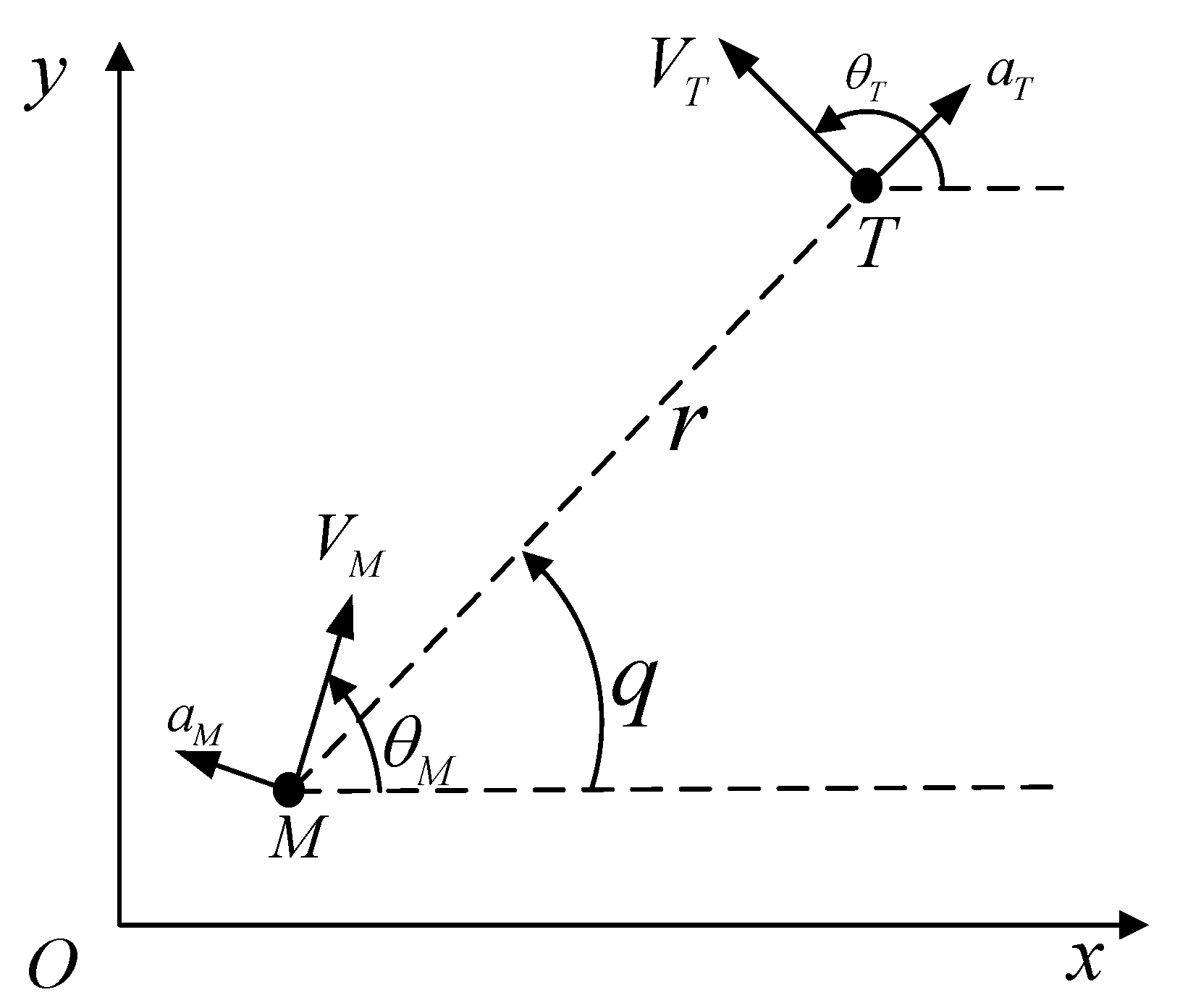
Figure 1. Follower-leader relative motion relationship.
Aerospace 10 00964 g001
Figure 2. Responses in Case 1 (small initial system conditions).
Aerospace 10 00964 g002
Figure 3. Responses in Case 2 (large initial system conditions).
Aerospace 10 00964 g003
Figure 4. Comparison of results in the two cases.
Aerospace 10 00964 g004
Table 1. Miss distance in Case 1 and Case 2.
Guidance MethodCase 1 (m)Case 2 (m)
FGLA7.6712.54
FGLAA 7.35 × 10 4 2.55
proposed FGLAA (full state) 6.34 × 10 4 8.95 × 10 4
proposed FGLAA (partial state) 5.73 × 10 3 9.56 × 10 3
Disclaimer/Publisher’s Note: The statements, opinions and data contained in all publications are solely those of the individual author(s) and contributor(s) and not of MDPI and/or the editor(s). MDPI and/or the editor(s) disclaim responsibility for any injury to people or property resulting from any ideas, methods, instructions or products referred to in the content.