
Model Predictive Control Based Washout Algorithm Design for Flight Simulator Upset Prevention and Recovery Training

1
School of Aeronautics and Astronautics, Shanghai Jiao Tong University, Shanghai 200240, China
2
COMAC (Commercial Aircraft Corporation of China, Ltd.) Shanghai Aircraft Customer Service Company, Shanghai 200240, China
*
Author to whom correspondence should be addressed.
Aerospace 2023, 10(10), 886; https://doi.org/10.3390/aerospace10100886
Submission received: 20 September 2023
/
Revised: 10 October 2023
/
Accepted: 13 October 2023
/
Published: 16 October 2023
(This article belongs to the Section Aeronautics)
Abstract
:To migrate Loss of Control In-flight, the number one cause of aviation fatalities, pilots need to undergo upset prevention and recovery training with flight simulators. The fidelity of a moving base flight simulator is greatly dependent on the washout algorithm of the Stewart platform, which may reach the workspace limits when simulating the aircraft recovery from upset conditions. In this paper, a washout algorithm optimal design method based on the model predictive control technique is proposed for flight simulator upset prevention and recovery training. The parameters of the washout algorithm are calculated directly based on the platform model, and the system limits are explicitly taken into account. The human perception model is incorporated into the optimization problem, for which the objective is to minimize the pilot’s perceived motion mismatch between the real flight and the simulator training. Simulations are conducted and compared with the classical filter-based washout algorithm. Responses of the flight simulator model show that the proposed method can improve the motion cueing effect when the aircraft is in upset conditions.
1. Introduction
Loss of Control In-flight (LOC-I) has become the primary cause of aviation fatalities in recent years [1]. One of the important LOC-I factors is that the flight attitude or airspeed of the aircraft is outside the normal bounds of operation, i.e., upset conditions [2,3]. Specific values are defined for such unintentional conditions: (1) pitch attitude greater than 25 deg with nose up; (2) pitch attitude greater than 10 deg with nose down; (3) bank angle greater than 45 deg; (4) within the above parameters but flying at an inappropriate airspeed [4]. Those values may vary among airplane models. In order to improve commercial aviation flight safety, the Federal Aviation Administration (FAA) issued AC 120-111 in 2015, which describes the recommended practice and guidance for airplane Upset Prevention and Recovery Training (UPRT). All FAA Part 121 air carriers are required to implement the UPRT regulations on flight simulators of level C or above.
A moving base flight simulator generally uses the Stewart platform as its source for motion to simulate the aircraft movement in the air. However, when approaching or exceeding the normal flight envelope, it is difficult to simulate the continuous movement and rapid change of the recovery from the upset as in a real aircraft due to the limited workspace of the flight simulator. If the motion cues received by pilots are quite different from the real flight, it may lead to negative transfer effect [5]. That means, the training on a flight simulator leads pilots to conduct incorrect responses and/or misunderstand the behavior of the aircraft in real flight.
The classical filter-based washout algorithm is the most widely used motion cueing algorithm for simulation of motion effects in a flight simulator. Although the structure of the classical washout algorithm is simple, it is a time-consuming and high-cost process in practical applications to tune the algorithm parameters based on the pilot’s subjective feedback [6,7]. To save time and cost, objective evaluation methods have been studied since the early 2000’s. The idea of the objective motion cueing test was proposed to use the frequency response of the entire motion cueing system for performance evaluation [8,9]. Based on this idea, a generic algorithm was applied to optimize the parameters of the classical washout algorithm and demonstrated through the virtual simulation experiment [10]. However, whether based on subjective or objective evaluation methods, the limits of the simulator platform cannot be explicitly considered in the classical washout algorithm design process.
To address these issues, the model predictive control (MPC) based washout algorithm design technique has been studied in recent years, but mostly for driving simulators. Instead of the platform workspace boundary, the actuator positions and velocities were used as the constraints in the MPC-based washout algorithm design for a driving simulator [11,12]. To handle the platform limits more efficiently, a human vestibule perception model and a predictive strategy based on the availability of a virtual driver were introduced for washout algorithm design [13,14]. Simulation results showed that the model prediction algorithm could produce a better performance in the tilt coordinate channel than the classical filter-based washout algorithm, especially under the constraint of workspace [14]. However, there are few studies about MPC-based washout algorithm design for flight simulators, and in the extant studies, there is a lack of detailed modeling and simulation results to show the motion cueing effect under various upset conditions [15,16]. It is worth investigating whether the MPC-based washout algorithm design method provides pilots effective motion cues and simultaneously keeps the simulator within its workspace limits when the real aircraft is recovering from upset conditions.
The paper is organized as follows. Section 2 introduces the principle of the classical filter-based washout algorithm. In Section 3, the MPC-based washout algorithm optimization problem is formulated, which includes the model of the simulator platform and its constraints. The human vestibule perception model is also incorporated, and the optimization objective is to minimize the pilot’s perceived motion mismatch between the real flight and the simulator training. The setup of the UPRT simulation experiment is given in Section 4. The MPC-based and the filter-based washout algorithm design methods are compared through simulations. Finally, Section 5 concludes the paper.
2. Classical Filter-Based Washout Algorithm
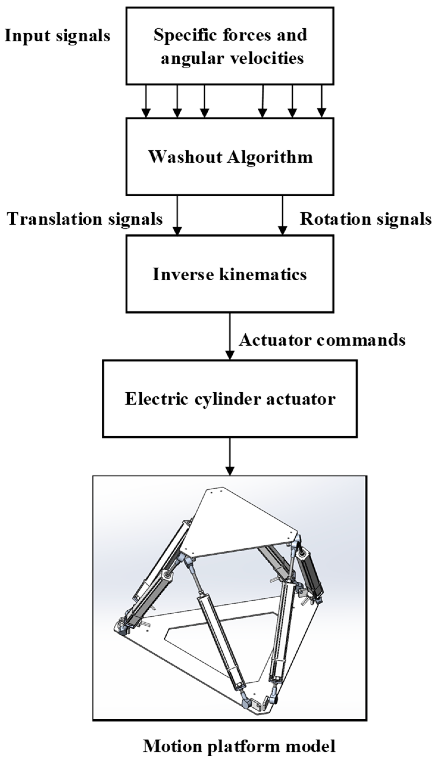
Figure 1 shows the schematic diagram of the entire motion cueing system, which consists of the washout algorithm, the inverse kinematics model of the motion platform, the dynamics model of the electrical cylinder actuators, and the forward kinematics model of the motion platform. In order to enable the platform to provide the pilot with the most realistic motion perception in the limited workspace, it is necessary to filter the simulated aircraft response through the washout algorithm. In addition, after one action is completed, the motion platform is supposed to return to its initial position to prepare for the next action; this is also achieved by the washout algorithm [17,18,19].
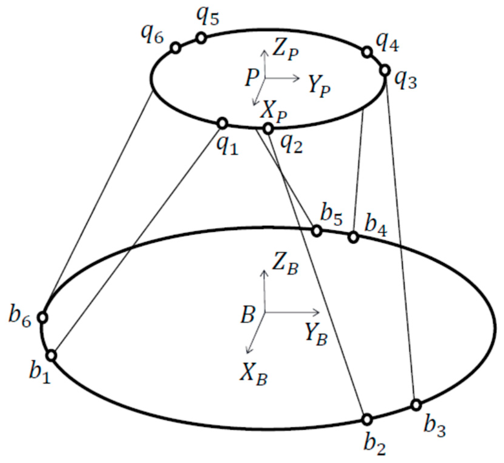
The motion of the aircraft or the flight simulator can be described in a coordinate system. There are three coordinate systems involved: (1) body axes with the aircraft’s centroid as the origin, (2) fixed axes of the motion platform (i.e., inertial axes), and (3) body axes with the moving platform’s centroid as the origin. The latter two are defined in Figure 2. In addition, the origin can be defined at the aircraft or simulator cockpit seat, respectively. These two coordinate systems can be obtained from the aircraft body axes or the platform moving axes by a simple transformation, or vice versa. In this paper, without causing confusion, no specific distinction is made for them.
By coordinate transformation, the translational acceleration and the angular velocity represented in the aircraft’s body coordinate system can be transformed to the fixed coordinate system of the motion platform. After processing these signals through the washout algorithm, the translational displacement and the rotational angle of the flight simulator can be obtained. The actuators are then driven accordingly to move the motion platform to simulate the movement of the aircraft in the air.
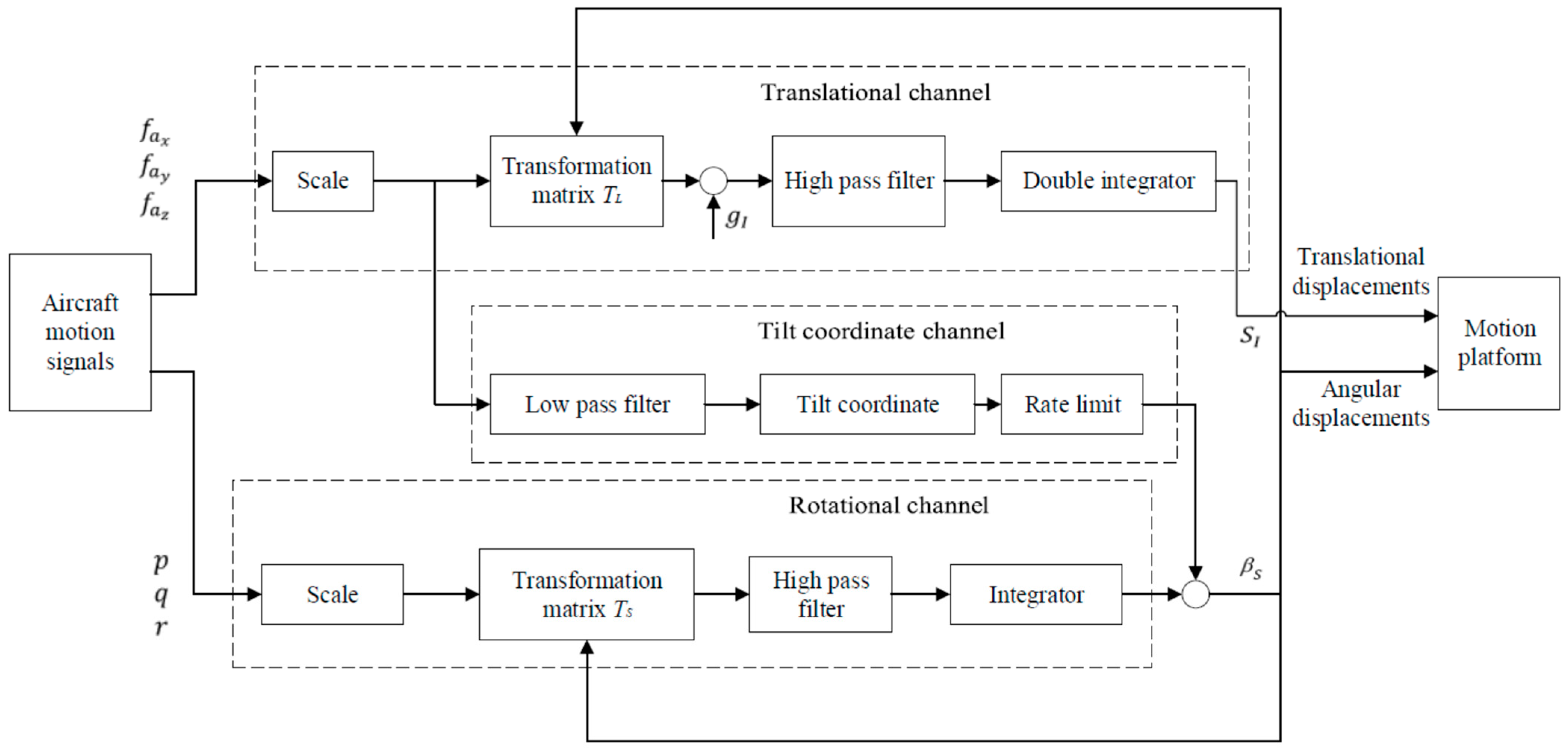
The classical filter-based washout algorithm is the most widely used in practical applications to tune the motion of the flight simulator [17,18,19,20,21]. The block diagram of the classical washout algorithm is shown in Figure 3. The input signals , , are the aircraft cockpit specific forces (non-gravitational force per unit mass, i.e., the difference between inertial acceleration and the acceleration due to gravity) in the body axes and , , are the aircraft angular rates. The outputs and represent the translational displacements and rotational angles of the moving platform, respectively.
2.1. Coordinate Transformation
The coordinate transformation involves the acceleration coordinate transformation and the angular velocity coordinate transformation.
It is assumed that the Euler angles are , , and with the rotation sequence of Z-Y-X. They are defined as three consecutive rotational angles about the initial Z axis, the temporary Y axis (after the first rotation), and the final X axis (after the second rotation), respectively. Denote , , and as basic rotation matrices. The expression of the acceleration coordinate transformation matrix (from the cockpit body axis to the fixed axes of the motion platform) is given below [22], where the acronym s stands for sine and c stands for cosine.
For the angular velocity coordinate transformation, the angular velocity of the cockpit in the body axes system must be converted to the rates of changes of Euler angles in the inertial coordinate system. It is known that the relationship between angular velocities (, , ) and time derivatives of Euler angles (, , ) can be written as follows [22].
The inverse transformation of the above equation gives
where the angular velocity transformation matrix relating the three body axis system rates to the three Euler rates is expressed as follows.
2.2. Filters
As shown in Figure 3, the translational channel is used to filter the instantaneous acceleration of the translational movements of the motion platform in order to avoid the translational movements beyond the limited workspace. The basic principle of the translational channel is as follows. First, the amplitude of the acceleration signal is scaled and the high-amplitude components for which the movement cannot be completed are filtered out. Then, a high-pass filter is used to filter out the low-frequency components to prevent the movement of the motion platform from exceeding the limited workspace. Afterwards, the acceleration signal is integrated twice to be converted to a linear displacement signal . Finally, the displacement signal is limited to ensure that the moving space of the platform is within its limitation. The transfer function of the high-pass filter in the translational channel is given by
where is the adaptive gain, is the damping ratio, and and are the natural cut-off frequencies of the first and second-order terms, respectively. Note that there are three such filters, corresponding to the three directions.
The rotational channel is used to provide the pilot with a sense of rotation. As shown in Figure 3, its working principle is similar to the translational channel with the process of scaling, transformation, high-pass filtering, and integration. The input signal is eventually converted to an angular displacement signal . Different from the translational channel, the input to the rotational channel is velocity, not acceleration, and therefore is obtained with integration once instead of twice in the translational channel. The transfer function of the high-pass filter in the rotational channel can be expressed as follows and the notations are similar to those in Equation (5).
The flight simulator platform can slowly return to the initial position at an angular velocity and translational acceleration less than the human sensory threshold [23,24], listed in Table 1, after completing a sudden movement, ensuring that the pilot cannot detect it.
In addition, the method of tilt coordination must be used in the flight simulator in order to achieve a continuous acceleration signal, aiming to simulate the low-frequency acceleration signals of the aircraft in the air through orientation of the gravity vector. When simulating a continuous acceleration signal in the lateral direction, the flight simulator platform rotates a specific angle around the longitudinal direction. Similarly, when simulating a continuous acceleration signal in the longitudinal direction, the flight simulator platform rotates a specific angle around the lateral direction. The tilt coordination channel can washout the continuous low-frequency acceleration signals in the longitudinal and lateral directions when the flight simulator moves in translation. The filters in both directions are assumed as second-order low-pass filters.
Denote the outputs of low-pass filters as and , which are the longitudinal and lateral low-frequency acceleration components, respectively. The tilt coordinate channel can convert the low-frequency translational acceleration into the tilt angles of the simulator platform. The relationship between the translation and rotation is given below.
It is observed from Equations (5)–(7) that there are more than twenty parameters to be tuned. Therefore, the tuning process is very complicated and time-consuming. Moreover, the actuator constraints of the simulator platform cannot be explicitly considered during the design process. This might be no problem for the simulation of aircraft motion in the normal flight envelop, but not for the UPRT practice.
3. MPC-Based Washout Algorithm Design
This section will introduce the washout algorithm design method based on the MPC technique. Compared with the classical filter-based method, the MPC-based method can explicitly take the actuator constraints into account so that the workspace of the platform can be utilized to a greater extent [11,14]. The MPC-based method is essentially a model-based optimal control strategy that computes the reference motion signals of the platform by solving an optimization problem. The model consists of two parts: the motion platform model and the human vestibular system model.
3.1. Motion Platform Model
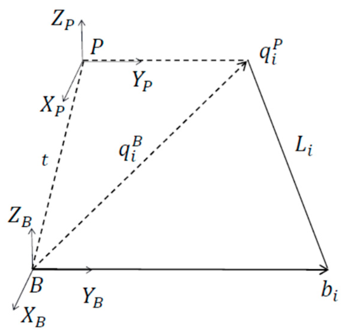
The inverse kinematic model of the Stewart platform is used in the MPC design. The platform consists of an upper moving platform, a bottom fixed base, and six connecting rods, each driven by a linear electric servo actuator. Take one rod as an example. As shown in Figure 4, the position vector of the rod length can be derived using vector arithmetic.
where all the vectors are represented in the fixed axes B. is the position vector of the joint where the rod is connected with the fixed base. is the position vector where the rod is connected with the moving platform, and there is
where is the position vector connecting the origins of the fixed and moving coordinate systems, is the rotation matrix from the moving axes P to the fixed axes B, and is the position vector represented in the moving axes P. Note that is actually the transformation matrix given in Section 2.
Substituting Equation (11) into Equation (10) and introducing the unit vector along the rod vector , there is
where .
Denote the Jacobian matrix as and the relationship between the velocities of the moving platform and the actuator rod can be expressed as follows.
where . and are the translational and rotational velocity vectors of the moving platform, respectively, and both are represented in the moving axes P.
Differentiating Equation (12) for and then combining them gives the inverse of the Jacobian matrix.
Note that the length of six rods has an upper and lower bound in position due to the excursion of linear actuators, and that this is also true for the velocity. The inequality constraints of the following form can be directly considered in the MPC-based washout algorithm design.
3.2. Human Vestibular System Model
The human vestibular system is located in the human inner ear and is composed of many different components. There are two important parts, semicircular canals and otoliths, for motion cueing application. It must be noted that these organs exhibit strongly damped high-pass behavior and cannot sense information at velocities below the threshold [25]. Their dynamic models can be represented as a combination of linear transfer functions and nonlinear motion thresholds. Considering both computational time and real-time performance, nonlinearities due to thresholds are generally not included and only linear transfer functions are used to model the human vestibular system. The model parameters related to the linear transfer functions were specified by different researchers to determine which cues are important and should be presented [25].
The semicircular canals are composed of three mutually perpendicular annular tubes and are used to sense the rotational motion. The angular acceleration is sensed for the low frequency range (<0.1 Hz), the angular displacement is sensed for the high frequency range (>5 Hz), and between them the angular velocity is sensed [26]. A second-order transfer function is generally used to describe this characteristic, and the one proposed by Telban [27] is the most widely used.
where is the angular velocity of the aircraft or the simulator, and is the perceived angular velocity by the pilot in one of the three rotational degrees of freedom.
Similarly, a second-order transfer function is used to model the otoliths and describe the perception of linear motion [27].
where is the specific force of the aircraft or the simulator and is the perceived specific force by the pilot in one of the three translational degrees of freedom.
To apply the MPC technique, the above transfer function models (16) and (17) are converted to the state-space form [28]. For the semicircular canals,
where the input and the output . For real applications, an approximation is usually adopted where and [28]. The state-space matrices are obtained by combining the data in three rotational degrees of freedom, and , , , .
For the otoliths,
where the input and the output . Assembling the state-space data in three translational degrees of freedom gives , , , and . Due to the effect of tilt coordination, a complete model of the otolith should also include as states and the state-space matrices are augmented as follows.
where and the input is also augmented as .
Combining the state-space equations of the semicircular canals and otoliths gives the human vestibular system model, for which the state-space matrices are given as follows.
3.3. Washout Algorithm Optimization
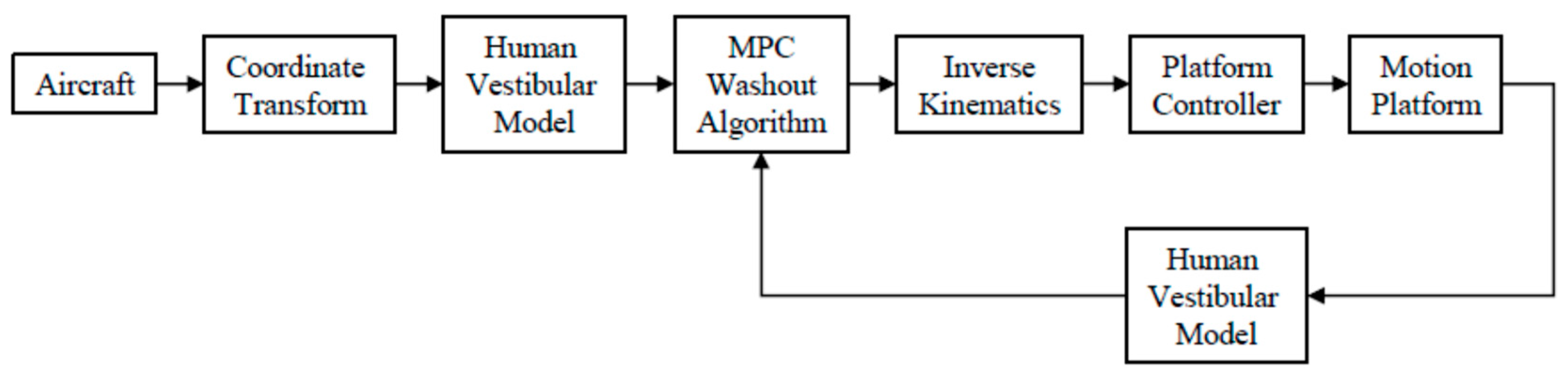
Figure 5 is the block diagram for the MPC-based motion cueing system, in which the washout algorithm computes the desired motion signals of the platform based on the perceived aircraft motion and the perceived simulator motion.
At the design stage, the models of the motion platform and human vestibular system are first combined together. The continuous-time system model is formulated and then discretized in order to apply the MPC technique.
Assume that the prediction horizon as and the control horizon as . The system state and output at the future moment can be determined by the state at the current moment and the control in the future period. Note that the current state is known. Thus, if defining the objective function based on the predicted system state and/or output, the control in the future time becomes the only variable. The control problem is thus converted into an optimization problem.
The objective function to be minimized is defined as follows.
where and are weighting matrices, and both are positive definite. The input and output constraints are and . The problem is to find the optimal control under the constraints by minimizing the difference between the output and the reference , i.e., achieving reference tracking. Commercial solvers are available for solving such a constrained quadratic programming problem.
For the washout algorithm design, the reference in Equation (23) represents the pilot’s perceived motion in the real flight. For the flight simulator, can be obtained by coordinate transforming the flight dynamics simulation data and then processing it through the human vestibular system model. The output in Equation (22) is defined as the perceived motion in the simulator. The displacements, velocities, and accelerations of the motion platform in the directions of surge, sway, heave, roll, pitch, and yaw are constrained according to the actuator limitations.
4. Simulation and Discussion
In this section, the proposed MPC-based washout algorithm optimization method is tested and compared with the classical filter-based method. Simulations are conducted to assess whether the MPC-based washout algorithm can provide pilots with better motion cues when the aircraft is entering or recovering from upset conditions.
4.1. Aircraft Simulation Model and Parameters
The aircraft model used in this paper is Generic Transport Model (GTM), which is a wide-envelope aircraft model developed by NASA and Boeing to help design and test upset recovery control techniques. A 5.5% dynamically scaled GTM model is publicly available, which is a high-fidelity aircraft simulation model with a wide range of aerodynamic data obtained through wind tunnel tests [29,30].
To study the performance of the flight simulator, a full-scale aircraft nonlinear dynamics model is obtained based on the scaled GTM model. The reconfiguration of parameters is conducted according to the scaling ratio of 5.5%, including the wingspan, the average aerodynamic chord length, etc. The wing area is scaled by times. The weight of the full-scale model is set to 185,000 lbs, which represents a mid-value weight for a medium-sized transport aircraft. The moments of inertia of the full-scale model are listed in Table 2.
In addition, the parameters of actuators and engines undergo necessary adjustments. The natural frequencies of the elevator, aileron, rudder, and other control surfaces are changed to 2 Hz, and their deflection rates are limited to 60°/s. The engine thrust is scaled according to the scaling ratio of [10].
4.2. Motion Platform Simulation Model and Parameters
The bottom block in Figure 1 shows the 3D modeling of the Stewart platform. The values of its geometric parameters are selected with reference to the relevant simulator models on the market and are listed in Table 3. Note that the origin is at the center of the base for or the moving platform for . The length of each rod changes between and under the action of the linear actuator. Table 4 defines the limited motion workspace in terms of the translational and rotational displacement, velocity, and acceleration of the point .
The simulation model of the motion platform includes kinematics, dynamics, and motion control modules. The Jacobian matrix derived in Section 3 is used to establish the relationship between the speeds of the connecting rod and the moving platform. Dynamic equations of motion of the connecting rod and the moving platform are derived by applying Lagrangian formulation and Newton–Euler method. In addition, a visualization model is generated based on the SolidWorks model using the MATLAB2022a Simscape Multibody Link plugin.
4.3. UPRT Simulation and Comparison
FAA provides a standard training program for upset recovery, and different upset scenarios are discussed [4]: (1) Nose low, wings level; (2) Nose high, wings level; (3) high bank angles, nose low; (4) high bank angles, nose high. In this paper, all four scenarios are simulated to verify the idea of MPC-based motion cueing algorithm optimization for flight simulator UPRT practice.
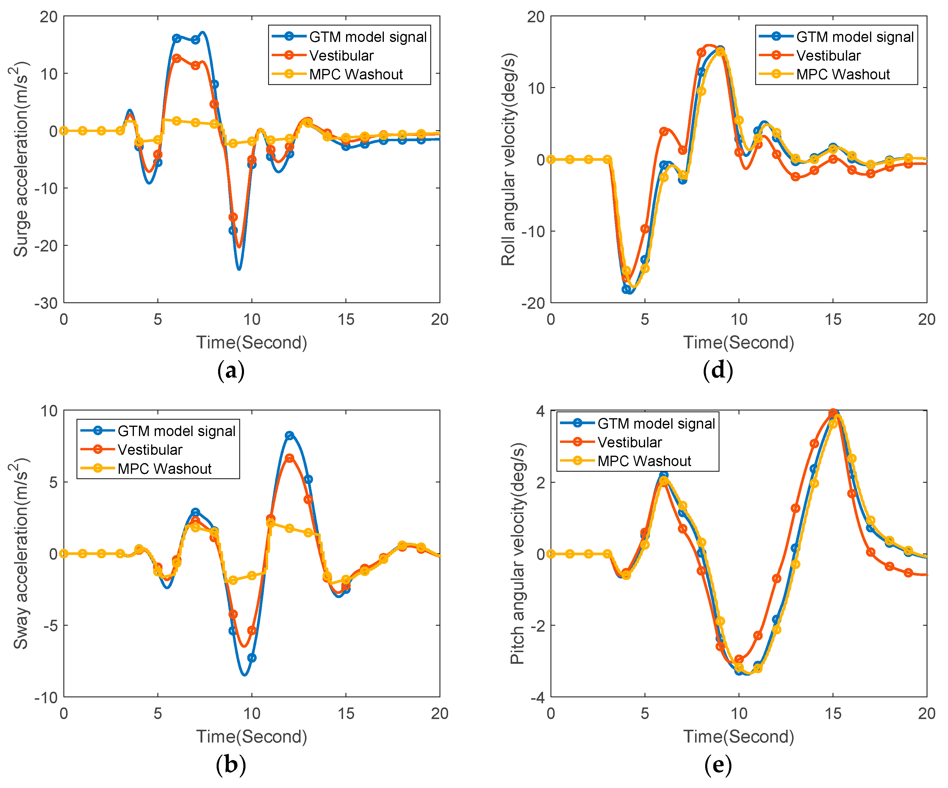
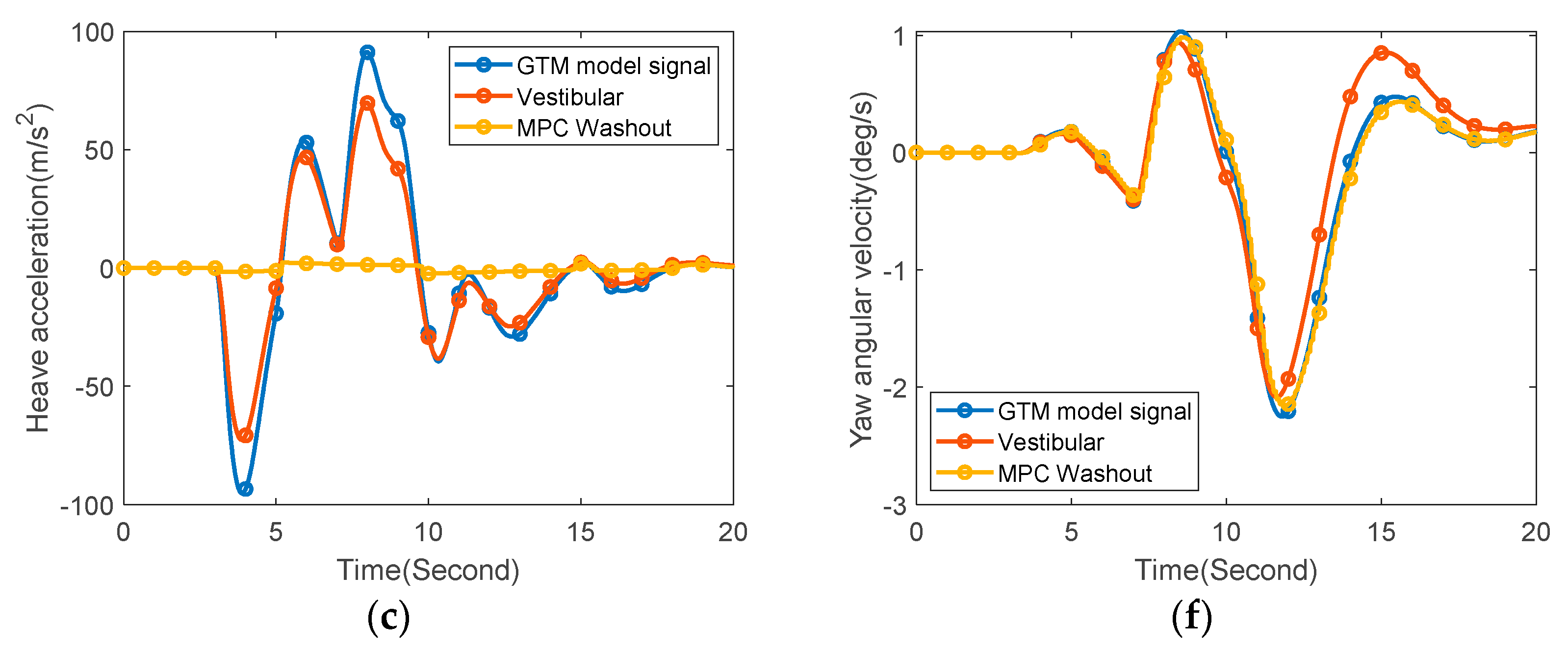
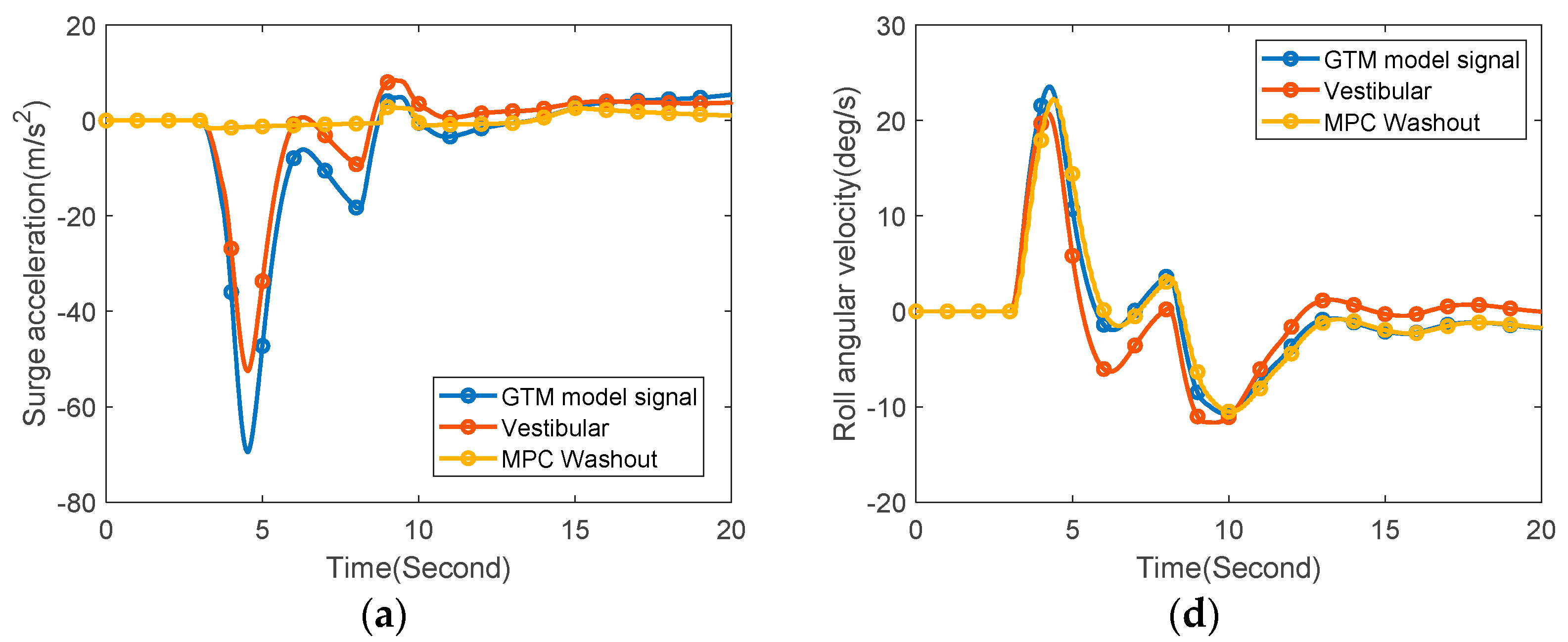
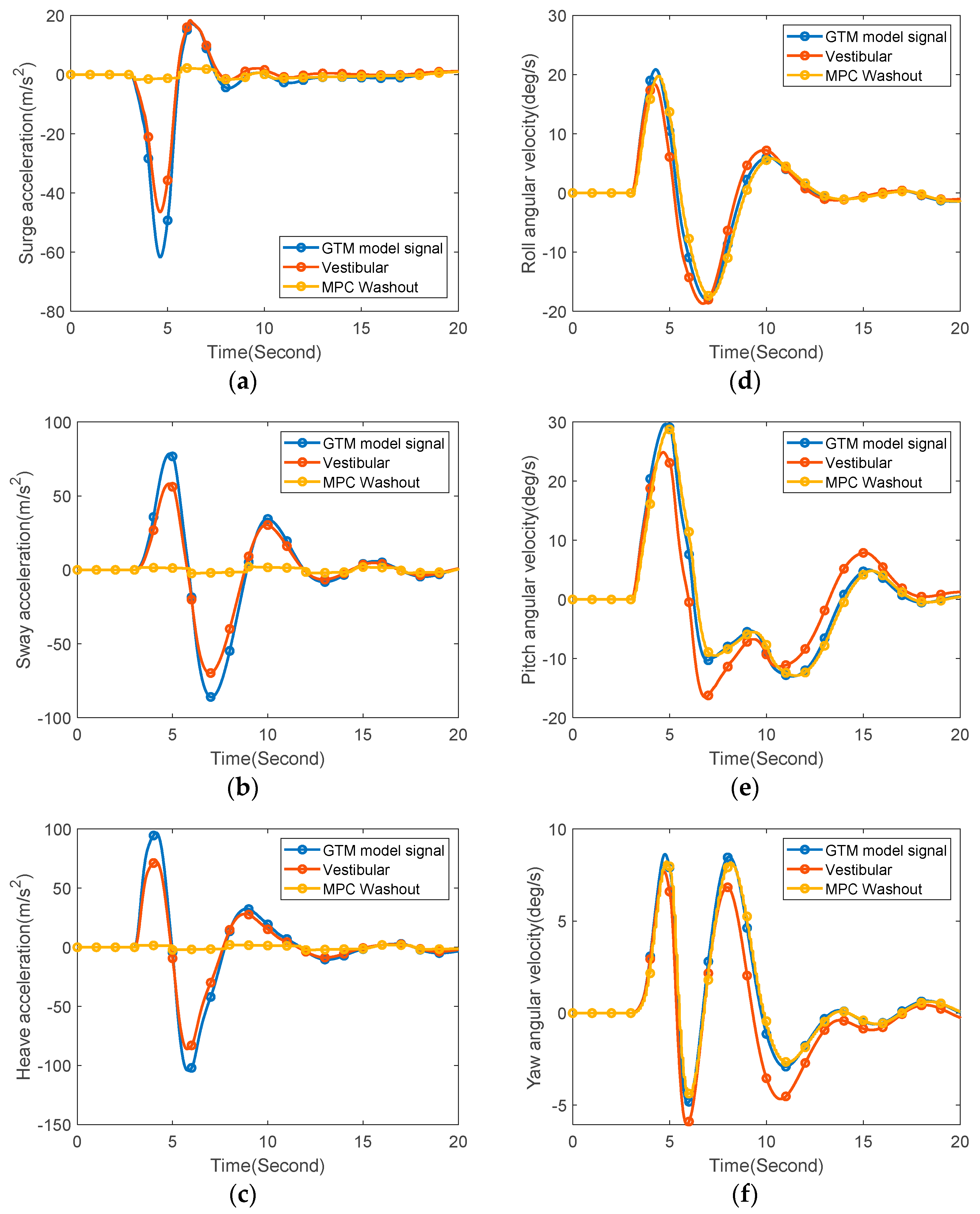
An MPC-based washout algorithm is designed using the method described in Section 3. The resulting motion cueing system is constructed in MATLAB Simulink for performance testing. The response of the full-scale GTM aircraft model following the recommended recovery procedure is obtained and the pilot’s perceived aircraft motion is used as the input signals to the washout algorithm. The simulation results for the first scenario are shown in Figure 6, where three curves are plotted for each degree of freedom, including the aircraft response, the perceived aircraft motion, and the actual simulator motion.
It can be observed that the simulator provides good motion cues in all three rotational degrees of freedom despite the actuator constraints and the platform workspace limitations. The perceived angular velocities of the motion platform are close to the real or the perceived aircraft motion. On the other hand, because of relatively large accelerations of the aircraft at upset conditions, the tracking performance for the translational motion is not as good as the rotation. Note that although the motion platform provides translational accelerations with lower amplitudes than the real flight, their phases of the translational motion are consistent with each other.
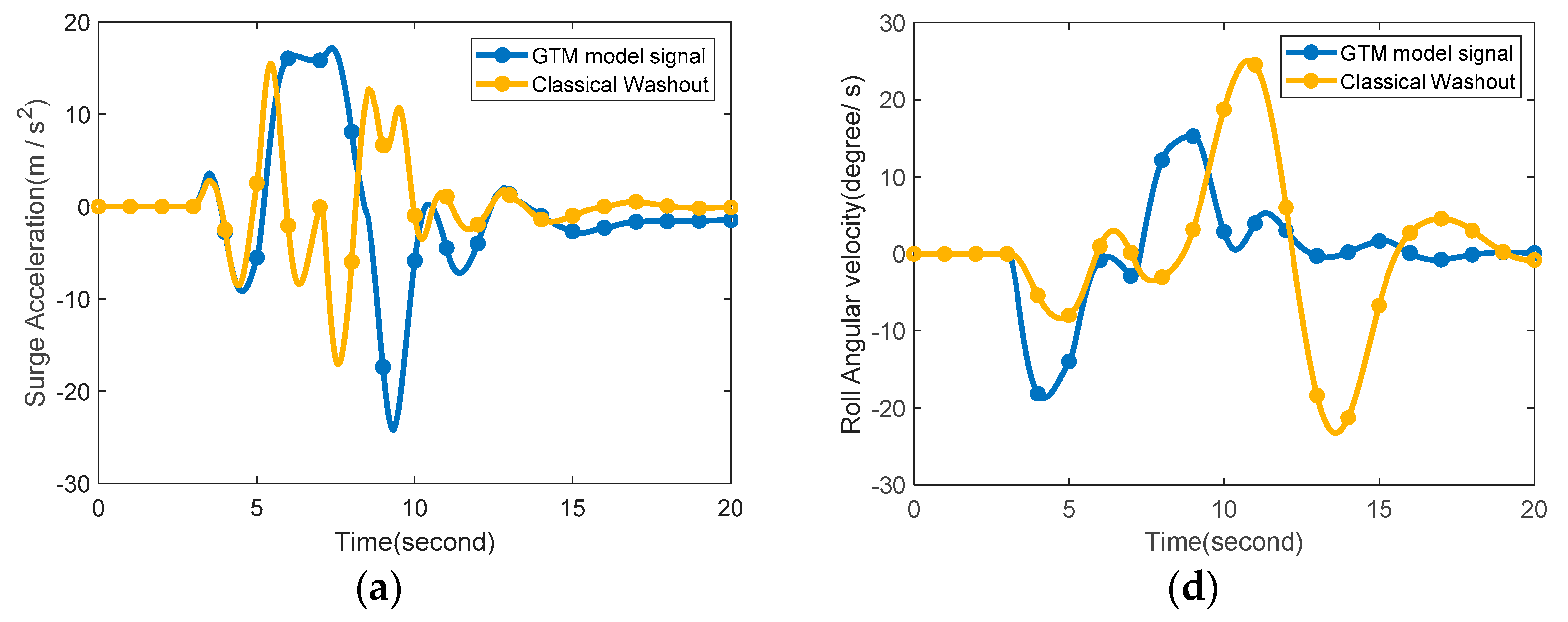
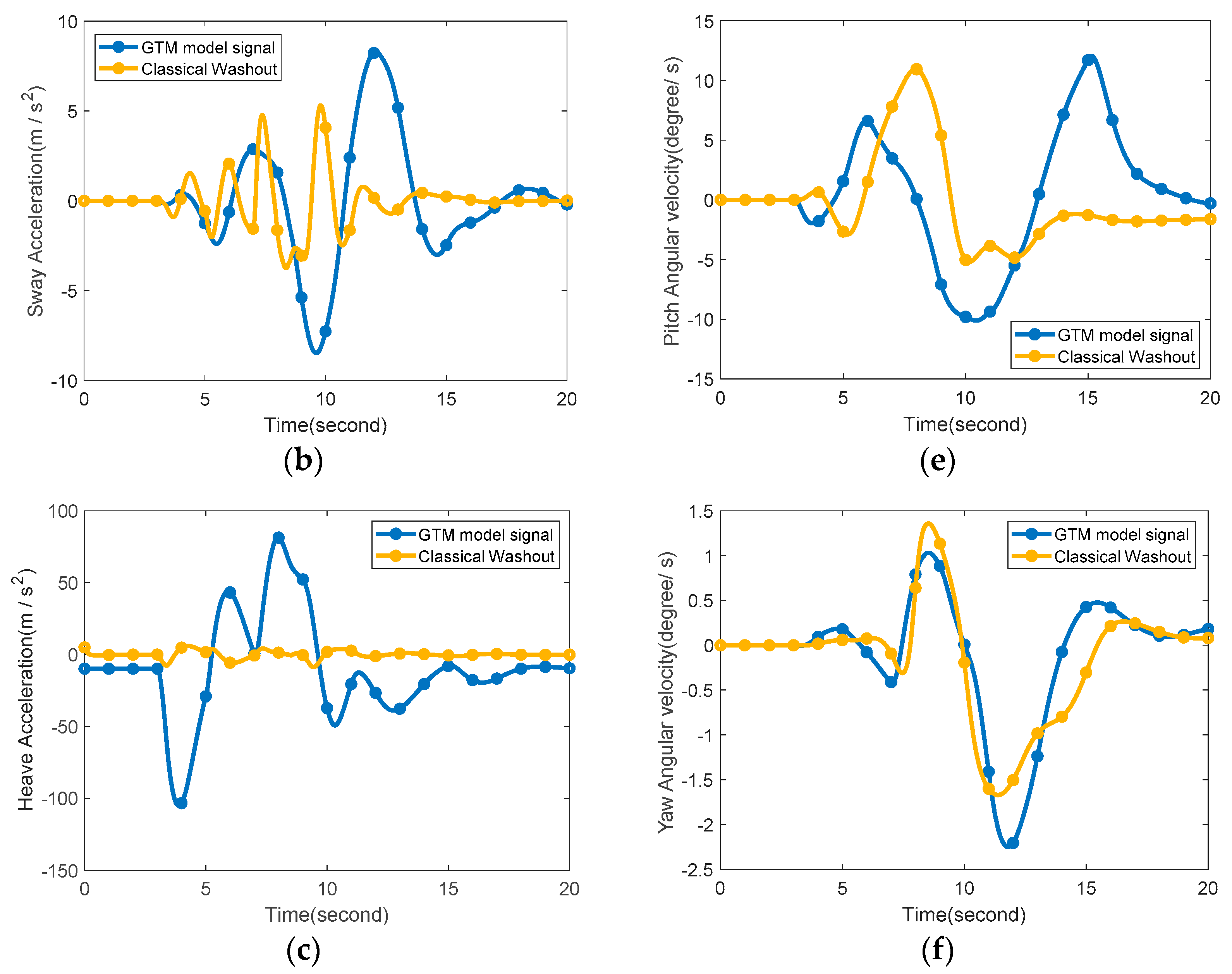
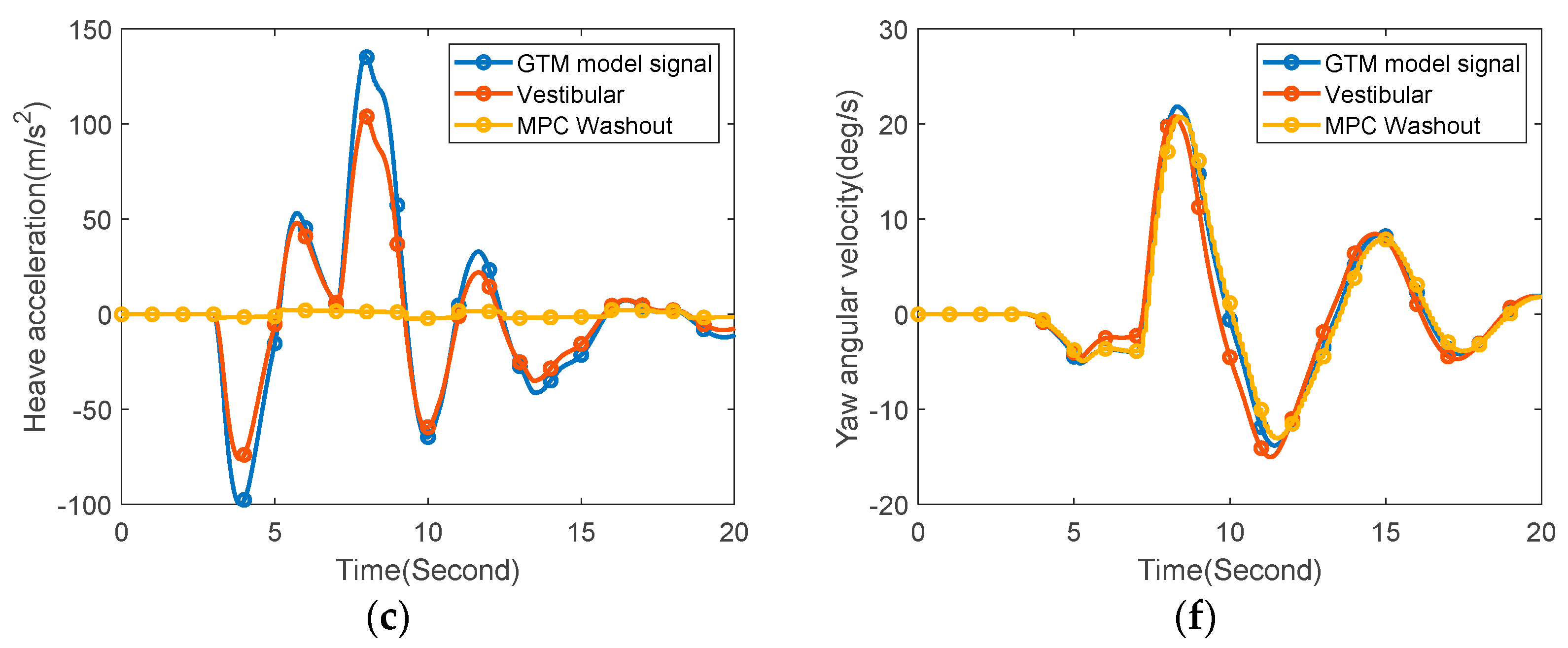
To make a valid performance assessment, the classical filter-based washout algorithm is also designed for comparison. The parameter tuning of the washout algorithm is formulated as a multi-objective optimization problem, for which the cost function is defined based on the objective motion cueing test proposed by International Civil Aviation Organization. The Pareto-optimal solution set is obtained through the Pareto pattern searching and the optimization result is determined according to the Pareto-front [31]. Similar to the MPC-based method, assume that the aircraft is in the nose low, wings level upset situation. The acceleration and angular rate information of the full-scale GTM model is used as the input of the washout algorithm. The motion platform is driven to move with the output of the washout algorithm as the command.
The corresponding simulation results are shown in Figure 7. It is obvious that the performance of the classical filter-based washout algorithm is much worse than the performance of the MPC-based one. The rotational movement of the platform has a similar trend to the input, but with certain phase lag. For the translational motion, the acceleration amplitudes for surge and sway directions are close to the input. However, the phases of the platform and the aircraft responses do not match with each other. One of the main reasons is that the limited workspace of the motion platform and the constraints of the servo electric cylinders are not explicitly considered in the design.
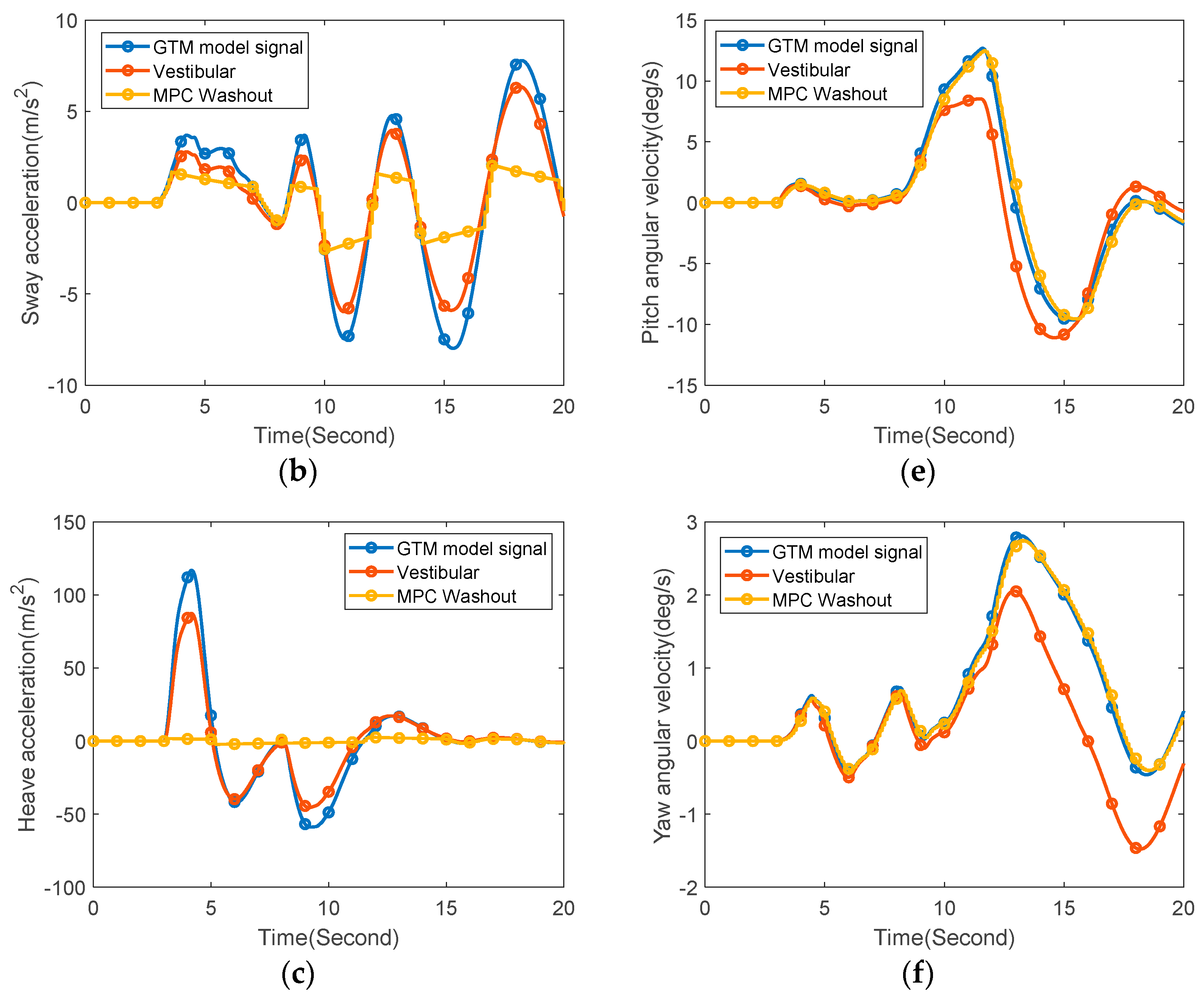
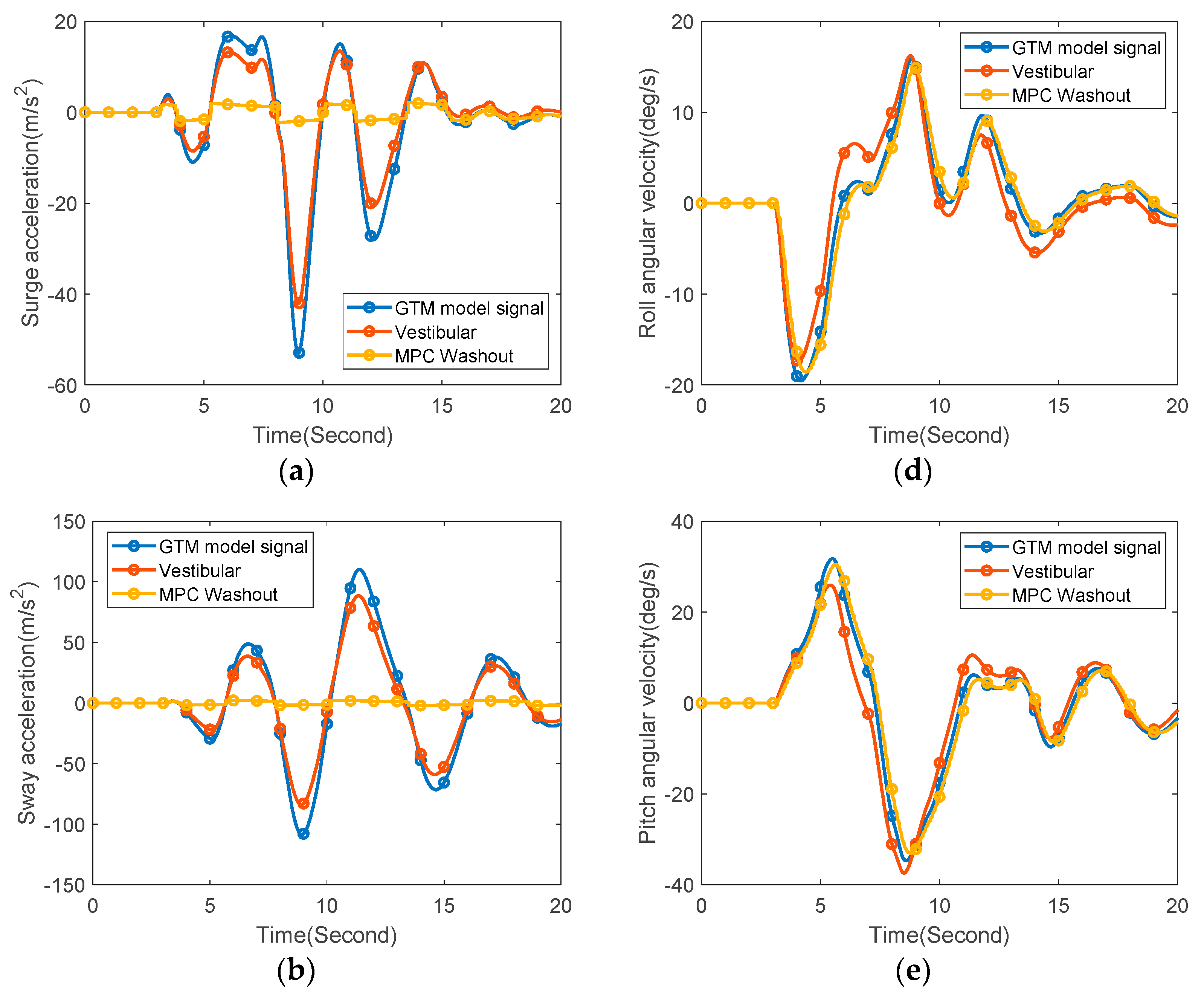
Simulation experiments for the other three upset scenarios are also conducted, and the results are shown in Figure 8, Figure 9 and Figure 10. Similar to scenario 1, the simulator can provide effective motion cues for the rotational motion when the aircraft is in upset conditions. For the translational motion, although the simulator moves with a much smaller acceleration than the real flight due to the limitation of the motion space, the phases of the simulator and the aircraft are almost the same.
5. Conclusions
In this paper, the MPC-based technique is applied to design the washout algorithm for the flight simulator. Different from previous studies, the motion platform is supposed to conduct the UPRT practice other than the flight simulation in the normal flight envelope. The MPC problem is formulated based on the mathematical model of the Stewart platform and the human vestibular system. The actuator constraints and the workspace limitations are explicitly taken into account in the design process. The objective of the optimization problem is to minimize the difference between the perceived simulator and aircraft motion signals while keeping the platform within the limited workspace. UPRT simulations are conducted for the four upset scenarios provided by FAA. The performance of the MPC-based and classical filter-based washout algorithms is compared. Time responses of the flight simulator model show that the proposed method can greatly improve the motion cueing effect when the aircraft is in upset conditions. The simulator training with effective motion cues can help increase the pilot’s awareness of potential upset situations in real flight and improve the pilot’s ability to recover control of the aircraft that has exceeds the normal flight regime. To move the method towards real-world applications, further research involving human (instructor or trainee) perception is needed and will be studied in our future work.
Author Contributions
Conceptualization, Q.L. and B.L.; methodology, H.Z. and Y.T.; software, H.Z.; validation, Y.T. and Z.W.; data curation, Y.T. and Z.W.; writing—original draft preparation, Y.T. and B.L.; writing—review and editing, Q.L.; supervision, B.L.; project administration, Q.L.; funding acquisition, Y.T. and B.L. All authors have read and agreed to the published version of the manuscript.
Funding
This research was funded by Shanghai Jiao Tong University under Grants WH410141301 and GC4133037.
Data Availability Statement
All data used during the study appear in the submitted article.
Conflicts of Interest
The authors declare no conflict of interest.
References
- Boeing Commercial Airplanes. Statistical Summary of Commercial Jet Airplane Accidents, Worldwide Operations, 1959–2022. Available online: boeing.com/resources/boeingdotcom/company/about_bca/pdf/statsum.pdf (accessed on 30 July 2023).
- Cook, M.V. Flight Dynamics Principles, 3rd ed.; Elsevier: Waltham, MA, USA, 2007. [Google Scholar]
- Lu, N.; Meng, B. Risk Analysis of Airplane Upsets in Flight: An Integrated System Framework and Analysis Methodology. Aerospace 2023, 10, 446. [Google Scholar] [CrossRef]
- Carbaugh, D.; Rockliff, L.; Vandel, B. The Airplane Upset Recovery Training Aid; Revision 2; The Boeing Company/Airbus TR: Washington, DC, USA, 2008. [Google Scholar]
- Nobel, C. The Relationship between Fidelity and Learning in Aviation Training and Assessment. J. Air Transp. 2002, 7, 33–54. [Google Scholar]
- Grant, P.R.; Reid, L.D. PROTEST: An Expert System for Tuning Simulator Washout Filters. J. Aircr. 1997, 34, 152–159. [Google Scholar] [CrossRef]
- Weingarten, N.C. History of In-Flight Simulation at General Dynamics. J. Aircr. 2005, 42, 290–298. [Google Scholar] [CrossRef]
- Advani, S.; Hosman, R.; Potter, M. Objective Motion Fidelity Qualification in Flight Training Simulators. In Proceedings of the AIAA Modeling and Simulation Technologies Conference and Exhibit, Hilton Head, SC, USA, 20–23 August 2007. [Google Scholar]
- Hosman, R.; Advani, S. Design and Evaluation of the Objective Motion Cueing Test and Criterion. Aeronaut. J. 2016, 120, 873–891. [Google Scholar] [CrossRef]
- Jones, M. Enhancing Motion Cueing Using an Optimisation Technique. Aeronaut. J. 2018, 122, 487–518. [Google Scholar] [CrossRef]
- Dagdelen, M.; Reymond, G.; Kemeny, A.; Bordier, M.; Maȉzi, N. Model-Based Predictive Motion Cueing Strategy for Vehicle Driving Simulators. Control Eng. Pract. 2009, 17, 995–1003. [Google Scholar] [CrossRef]
- Garrett, N.J.I.; Best, M.C. Model Predictive Driving Simulator Motion Cueing Algorithm with Actuator-Based Constraints. Veh. Syst. Dyn. 2013, 51, 1151–1172. [Google Scholar] [CrossRef]
- Baseggio, M.; Beghi, A.; Bruschetta, M.; Maran, F.; Minen, D. An MPC Approach to The Design of Motion Cueing Algorithms for Driving Simulators. In Proceedings of the 14th International IEEE Conference on Intelligent Transportation Systems, Washington, DC, USA, 5–7 October 2011. [Google Scholar]
- Lamprecht, A.; Steffen, D.; Nagel, K.; Haecker, J.; Graichen, K. Online Model Predictive Motion Cueing with Real-Time Driver Prediction. IEEE Trans. Intel. Transp. Syst. 2022, 23, 12414–12428. [Google Scholar] [CrossRef]
- Wu, D.; Zhang, Z.; Zhao, J. Enhanced Upset Prediction and Recovery Training Motion Cueing Using Switched Model Predictive Control and Pilot Model. In Proceedings of the 2020 IEEE 2nd International Conference on Civil Aviation Safety and Information Technology, Weihai, China, 14–16 October 2020. [Google Scholar]
- Wu, D.; Zhao, J.; Gu, H. A Time Varying Model Predictive Motion Cueing Algorithm for Full Flight Simulator Upset Recovery Training. In Proceedings of the 2021 IEEE 3rd International Conference on Civil Aviation Safety and Information Technology, Changsha, China, 20–22 October 2021. [Google Scholar]
- Schmidt, S.F.; Conrad, B. Motion Drive Signals for Piloted Flight Simulators. NASA-CR-1601; NASA Ames Rsearch Center: Mountain View, CA, USA, 1970. [Google Scholar]
- Parrish, R.V.; Dieudonne, J.E.; Martin, D.J., Jr. Motion Software for a Synergistic Six-Degree-of-Freedom Motion Base. NASA TN D-7350; NASA Langley Research Center: Hampton, VA, USA, 1973. [Google Scholar]
- Baarpul, M. The Generation of Motion Cues on a Six-Degree-of-Freedom Motion System; Delft University Report LR-248; Delft University of Technology: Delft, The Netherlands, 1977. [Google Scholar]
- Grant, P.R.; Reid, L.D. Motion Washout Filter Tuning: Rules and Requirements. J. Aircr. 1997, 34, 145–151. [Google Scholar] [CrossRef]
- Wei, M.-Y. Design of a DSP-Based Motion-Cueing Algorithm Using the Kinematic Solution for the 6-DoF Motion Platform. Aerospace 2022, 9, 203. [Google Scholar] [CrossRef]
- Yechout, T.R. Introduction to Aircraft Flight Mechanics, 2nd ed.; AIAA: Blacksburg, VA, USA, 2014. [Google Scholar]
- Gong, X.M.; Li, X.H.; Wang, S.A. New Motion Cueing Algorithm for Driving Simulator Based on Variant Harmonic Wavelet. Int. J. Automot. Technol. 2015, 16, 117–126. [Google Scholar] [CrossRef]
- Tang, Z.; Hu, M.; Pei, Z.; Zhang, J. Adaptive Motion Cueing Algorithm Based on Fuzzy Tuning for Improving Human Sensation. In Proceedings of the 2016 IEEE Chinese Guidance, Navigation and Control Conference, Nanjing, China, 12–14 August 2016. [Google Scholar]
- Khusro, Y.R. MPC-Based Motion Cueing Algorithm for a 6 DOF Driving Simulator with Actuator Constraints. Master’s Thesis, Delft University of Technology, Delft, The Netherlands, 2020. [Google Scholar]
- Momani, A.; Cardullo, F. A Review of the Recent Literature on the Mathematical Modeling of the Vestibular System. In Proceedings of the 2018 AIAA Modeling and Simulation Technologies Conference, Kissimmee, FL, USA, 7 January 2018. [Google Scholar]
- Telban, R.J.; Cardullo, F.M. Motion Cueing Algorithm Development: Human-Centered Linear and Nonlinear Approaches. NASA Tech Report CR-2005-213747; NASA Langley Research Center: Hampton, VA, USA, 2005. [Google Scholar]
- Bruschetta, M.; Cenedese, C.; Beghi, A. A Real-time, MPC-based Motion Cueing Algorithm with Look-Ahead and Driver Characterization. Transp. Res. Part F 2019, 61, 38–52. [Google Scholar] [CrossRef]
- Jordan, T.; Langford, W.; Belcastro, C.; Foster, J.; Shah, G.; Howland, G.; Kidd, R. Development of a Dynamically Scaled Generic Transport Model Testbed for Flight Research Experiments. In Proceedings of the AUVSI Unmanned Systems, Anaheim, CA, USA, 1 January 2004. [Google Scholar]
- GTM_DesignSim. Available online: https://github.com/nasa/GTM_DesignSim (accessed on 12 August 2022).
- Zhou, H. Optimization and Design of Flight Simulator Washout Algorithm for Upset and Recovery Training. Master’s Thesis, Shanghai Jiao Tong University, Shanghai, China, 2022. [Google Scholar]
Figure 1.
Schematic diagram of the motion cueing system.

Figure 2.
Motion platform and its coordinate systems (B: fixed axes; P: moving axes; : the position where the rod is connected with the fixed base; : the position where the rod is connected with the moving platform).
Figure 2.
Motion platform and its coordinate systems (B: fixed axes; P: moving axes; : the position where the rod is connected with the fixed base; : the position where the rod is connected with the moving platform).

Figure 3.
Block diagram of the classical washout algorithm.

Figure 4.
Position vector diagram for a connecting rod.

Figure 5.
Schematic diagram of the MPC-based motion cueing system.

Figure 6.
Simulator responses using the MPC-based washout algorithm (Scenario 1): (a) Surge acceleration; (b) Sway acceleration; (c) Heave acceleration; (d) Roll angular velocity; (e) Pitch angular velocity; (f) Yaw angular velocity.
Figure 6.
Simulator responses using the MPC-based washout algorithm (Scenario 1): (a) Surge acceleration; (b) Sway acceleration; (c) Heave acceleration; (d) Roll angular velocity; (e) Pitch angular velocity; (f) Yaw angular velocity.


Figure 7.
Simulator responses using the classical filter-based washout algorithm: (a) Surge acceleration; (b) Sway acceleration; (c) Heave acceleration; (d) Roll angular velocity; (e) Pitch angular velocity; (f) Yaw angular velocity.
Figure 7.
Simulator responses using the classical filter-based washout algorithm: (a) Surge acceleration; (b) Sway acceleration; (c) Heave acceleration; (d) Roll angular velocity; (e) Pitch angular velocity; (f) Yaw angular velocity.


Figure 8.
Simulator responses using the MPC-based washout algorithm (Scenario 2): (a) Surge acceleration; (b) Sway acceleration; (c) Heave acceleration; (d) Roll angular velocity; (e) Pitch angular velocity; (f) Yaw angular velocity.
Figure 8.
Simulator responses using the MPC-based washout algorithm (Scenario 2): (a) Surge acceleration; (b) Sway acceleration; (c) Heave acceleration; (d) Roll angular velocity; (e) Pitch angular velocity; (f) Yaw angular velocity.


Figure 9.
Simulator responses using the MPC-based washout algorithm (Scenario 3): (a) Surge acceleration; (b) Sway acceleration; (c) Heave acceleration; (d) Roll angular velocity; (e) Pitch angular velocity; (f) Yaw angular velocity.
Figure 9.
Simulator responses using the MPC-based washout algorithm (Scenario 3): (a) Surge acceleration; (b) Sway acceleration; (c) Heave acceleration; (d) Roll angular velocity; (e) Pitch angular velocity; (f) Yaw angular velocity.


Figure 10.
Simulator responses using the MPC-based washout algorithm (Scenario 4): (a) Surge acceleration; (b) Sway acceleration; (c) Heave acceleration; (d) Roll angular velocity; (e) Pitch angular velocity; (f) Yaw angular velocity.
Figure 10.
Simulator responses using the MPC-based washout algorithm (Scenario 4): (a) Surge acceleration; (b) Sway acceleration; (c) Heave acceleration; (d) Roll angular velocity; (e) Pitch angular velocity; (f) Yaw angular velocity.


Table 1.
Values of human sensory threshold.
| Channel | Surge | Sway | Heave | Roll | Pitch | Yaw |
| Threshold | 0.17 m/s2 | 0.17 m/s2 | 0.28 m/s2 | 3.6°/s | 3.0°/s | 2.6°/s |
Table 2.
Moments of inertia of the full-scale aircraft model (unit: slug-ft2).
| 1,770,000 | 5,680,000 | 7,270,000 | 160,000 | 0 | 0 |
Table 3.
Parameter values for 3D modeling of the Stewart Platform.
| Parameter | Value (Unit: m) | Parameter | Value (Unit: m) |
|---|---|---|---|
| [0.302 1.214 0]T | [−0.210 0.918 0]T | ||
| [−0.302 1.214 0]T | [−0.9 0.277 0]T | ||
| [−1.202 −0.346 0]T | [−0.69 −0.641 0]T | ||
| [−0.901 −0.869 0]T | [0.69 −0.641 0]T | ||
| [0.901 −0.869 0]T | [0.9 −0.277 0]T | ||
| [1.202 −0.346 0]T | [0.210 0.918 0]T | ||
| 1.3 | 1.9 |
Table 4.
Workspace limitations of the Stewart Platform.
| Displacement | Velocity | Acceleration | ||||
|---|---|---|---|---|---|---|
| Max | Min | Max | Min | Max | Min | |
| Surge | 1.17 m | −0.87 m | 1.5 m/s | −1.5 m/s | 8 m/s2 | −8 m/s2 |
| Sway | 0.92 m | −0.92 m | 1.5 m/s | −1.5 m/s | 8 m/s2 | −8 m/s2 |
| Heave | 0.87 m | −0.76 m | 1.1 m/s | −1.1 m/s | 8 m/s2 | −8 m/s2 |
| Roll | 23° | −23° | 35°/s | −35°/s | 100°/s2 | −100°/s2 |
| Pitch | 22° | −22° | 30°/s | −30°/s | 100°/s2 | −100°/s2 |
| Yaw | 26° | −26° | 40°/s | −40°/s | 100°/s2 | −100°/s2 |
Disclaimer/Publisher’s Note: The statements, opinions and data contained in all publications are solely those of the individual author(s) and contributor(s) and not of MDPI and/or the editor(s). MDPI and/or the editor(s) disclaim responsibility for any injury to people or property resulting from any ideas, methods, instructions or products referred to in the content. |
© 2023 by the authors. Licensee MDPI, Basel, Switzerland. This article is an open access article distributed under the terms and conditions of the Creative Commons Attribution (CC BY) license (https://creativecommons.org/licenses/by/4.0/).
Share and Cite
MDPI and ACS Style
Tong, Y.; Zhou, H.; Wu, Z.; Li, Q.; Lu, B. Model Predictive Control Based Washout Algorithm Design for Flight Simulator Upset Prevention and Recovery Training. Aerospace 2023, 10, 886. https://doi.org/10.3390/aerospace10100886
AMA Style
Tong Y, Zhou H, Wu Z, Li Q, Lu B. Model Predictive Control Based Washout Algorithm Design for Flight Simulator Upset Prevention and Recovery Training. Aerospace. 2023; 10(10):886. https://doi.org/10.3390/aerospace10100886
Chicago/Turabian StyleTong, Yu, Haoyun Zhou, Zhao Wu, Qifu Li, and Bei Lu. 2023. "Model Predictive Control Based Washout Algorithm Design for Flight Simulator Upset Prevention and Recovery Training" Aerospace 10, no. 10: 886. https://doi.org/10.3390/aerospace10100886
Note that from the first issue of 2016, this journal uses article numbers instead of page numbers. See further details here.