

Experimental and Numerical Investigation of Novel Acoustic Liners and Their Design for Aero-Engine Applications

 , , , ,
Abstract
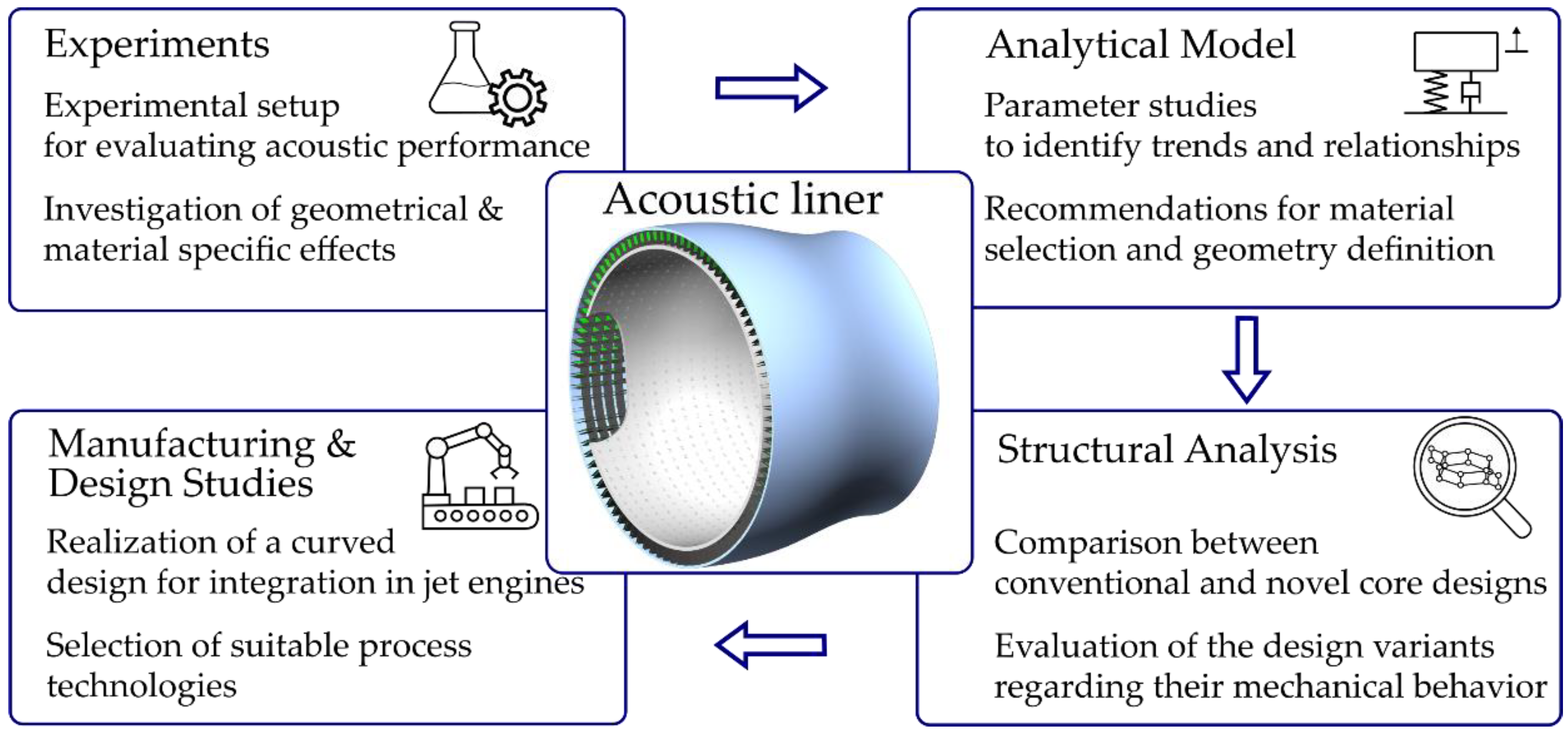
1. Introduction
2. Acoustic Analysis of Helmholtz Resonator with Flexible Walls and Results
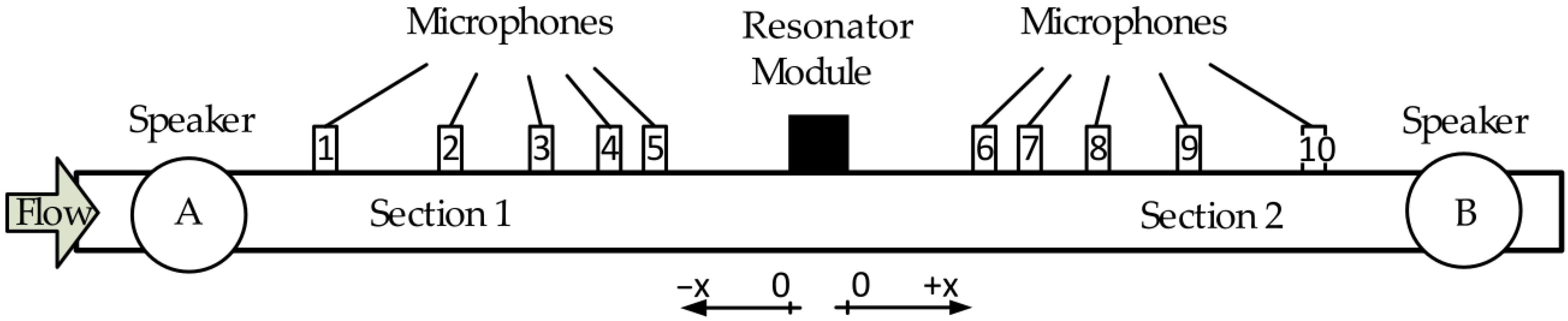
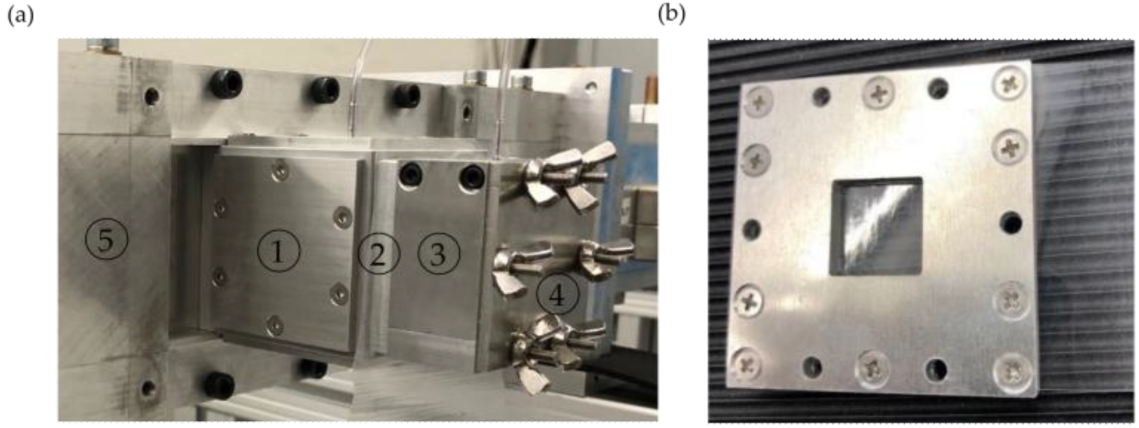
2.1. Experimental Setup for the HR
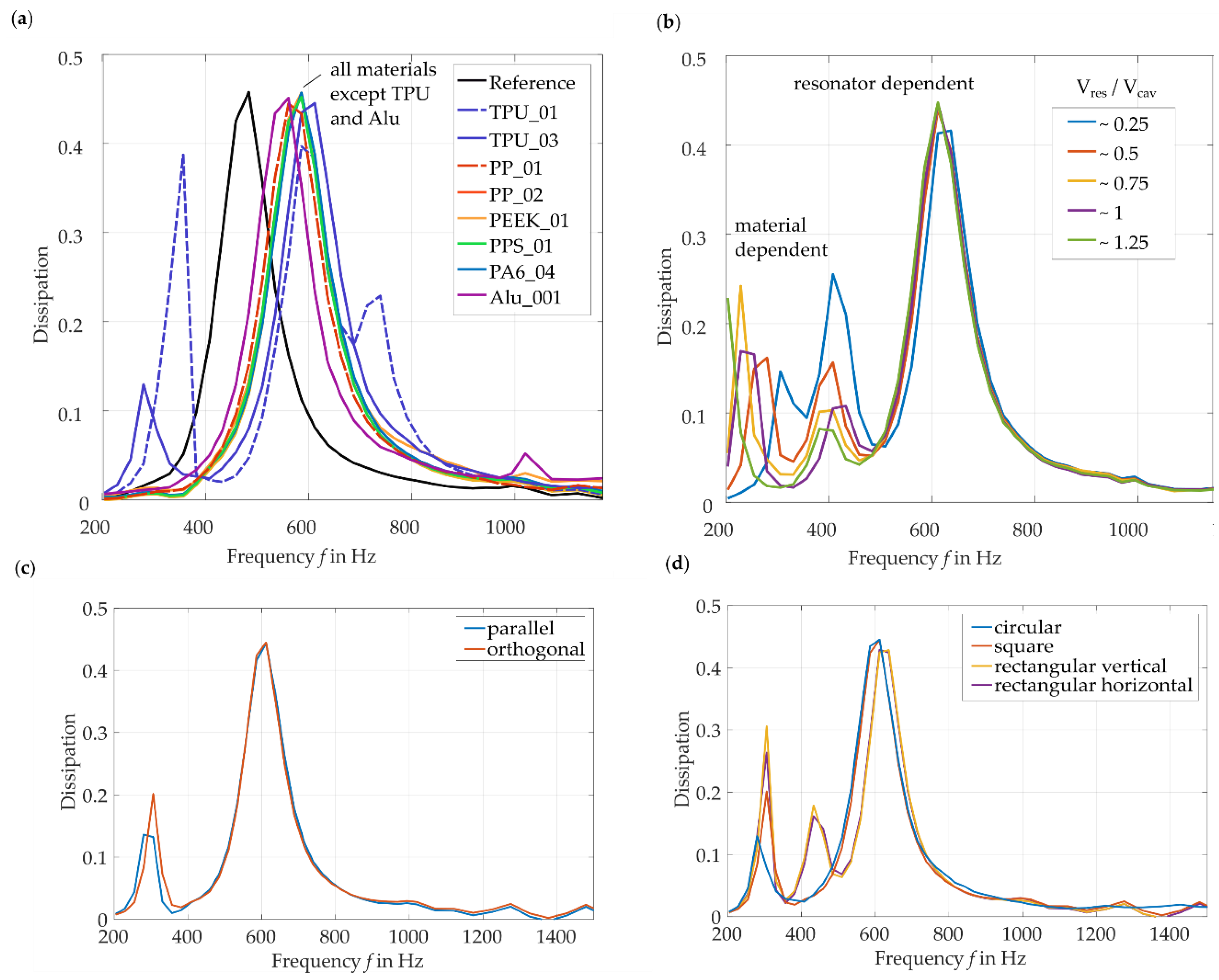
2.2. Results of Experimental Investigations of the FHR Design
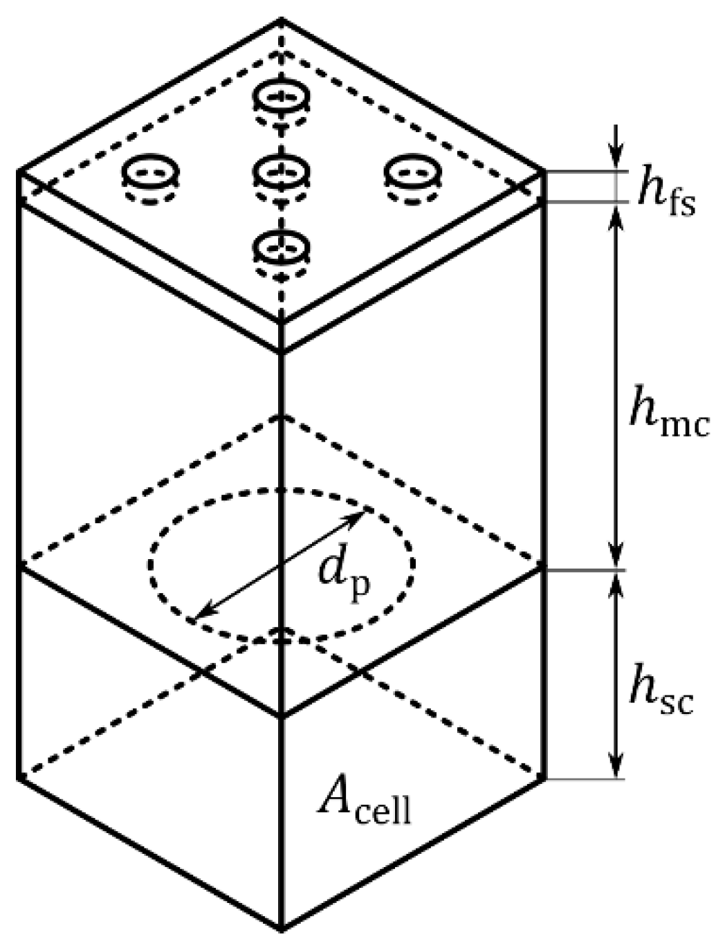
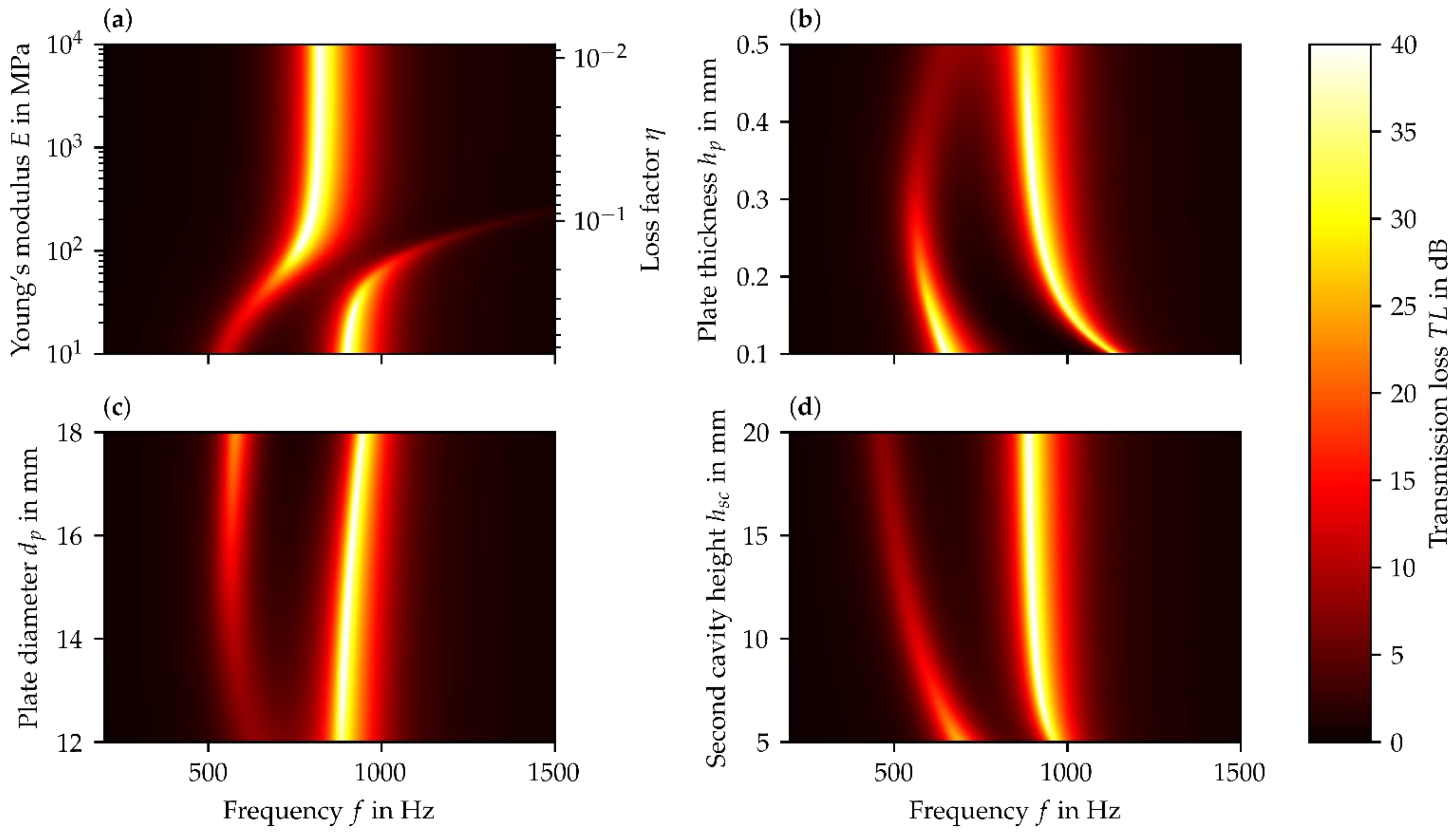
3. Semi-Analytical Parameter Studies for FHR and PR Liner Concepts
3.1. Result and Discussion of Parameter Studies for the FHR Concept
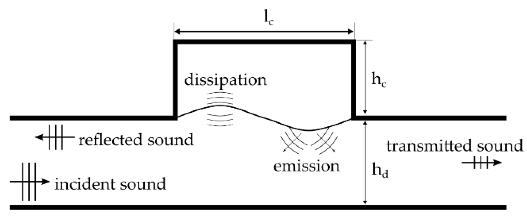
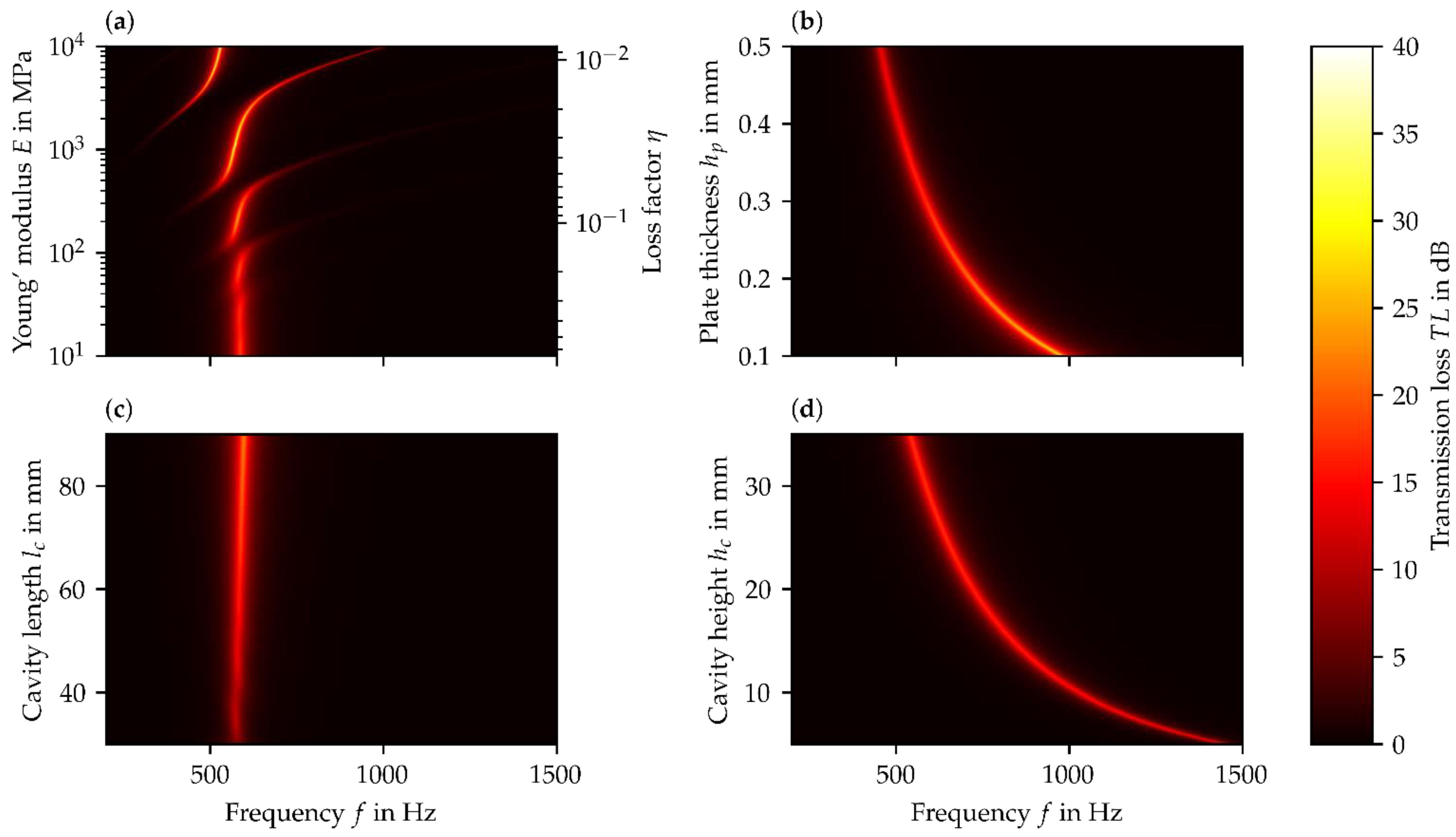
3.2. Result and Discussion of Parameter Studies for PR Liner Concept
4. Structural Mechanics Analysis and Results
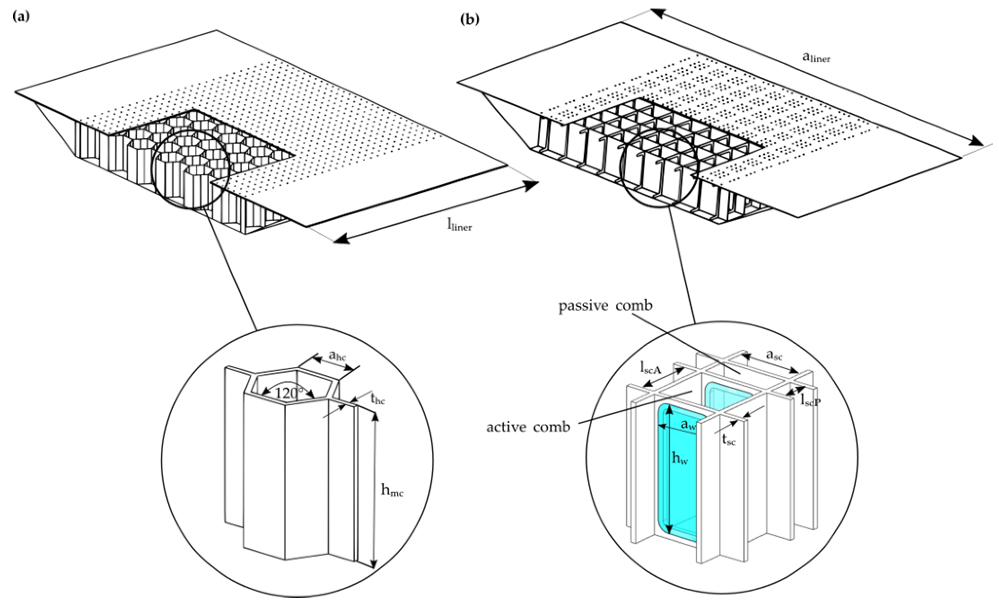
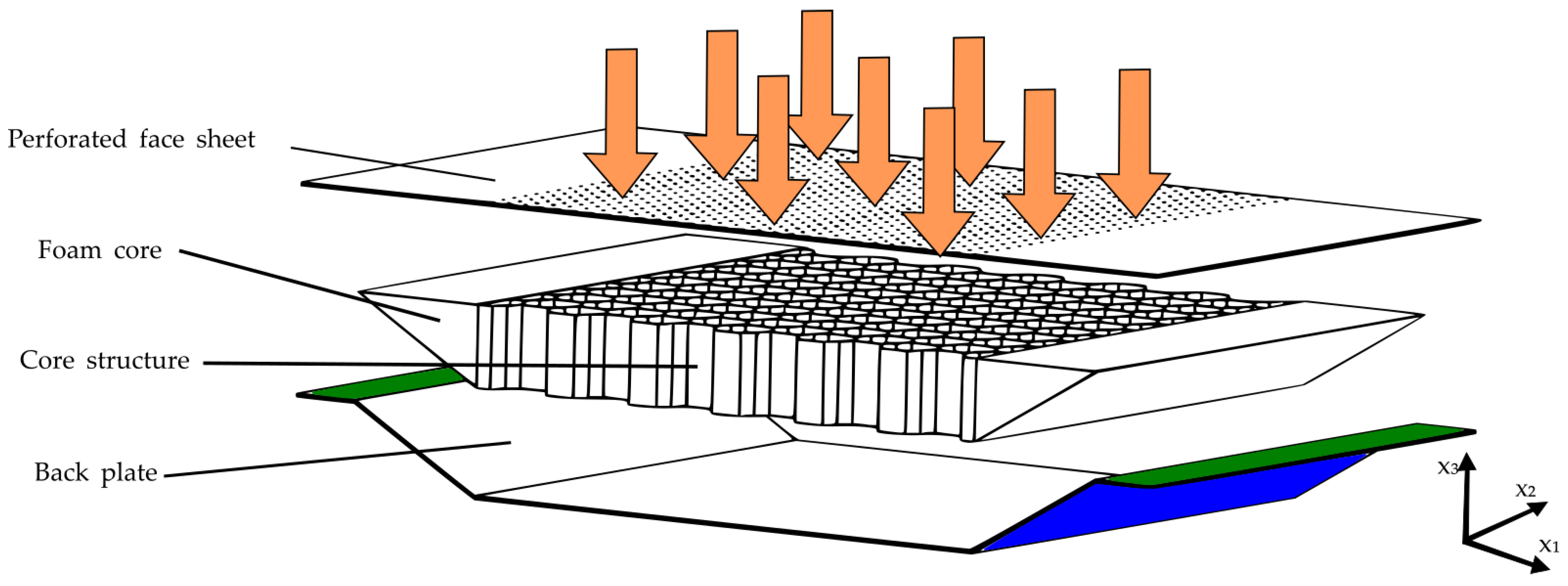
4.1. Structural Design
4.2. Materials
4.3. Modeling and Numerical Implementation
4.4. Constraints and Load Cases
- global pressure loads due to pressure differences between the face sheet and the back side of the back sheet
- local loads due to maintenance
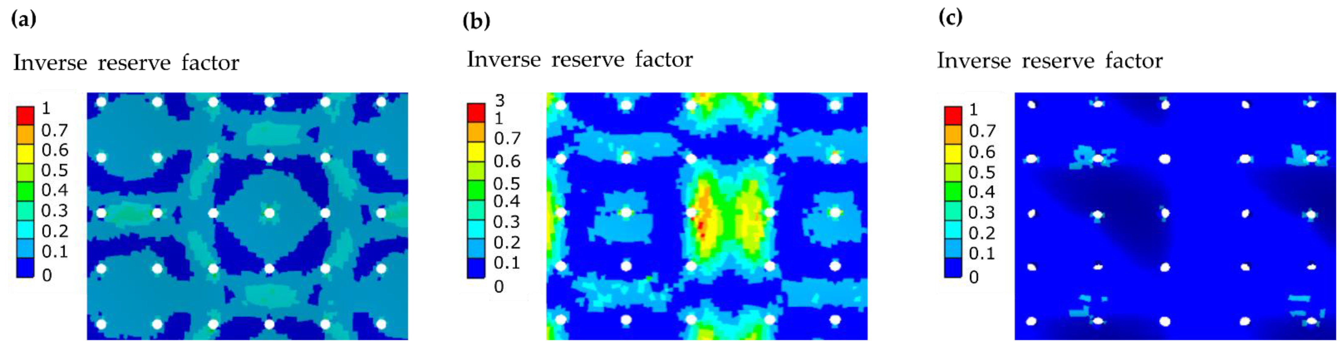
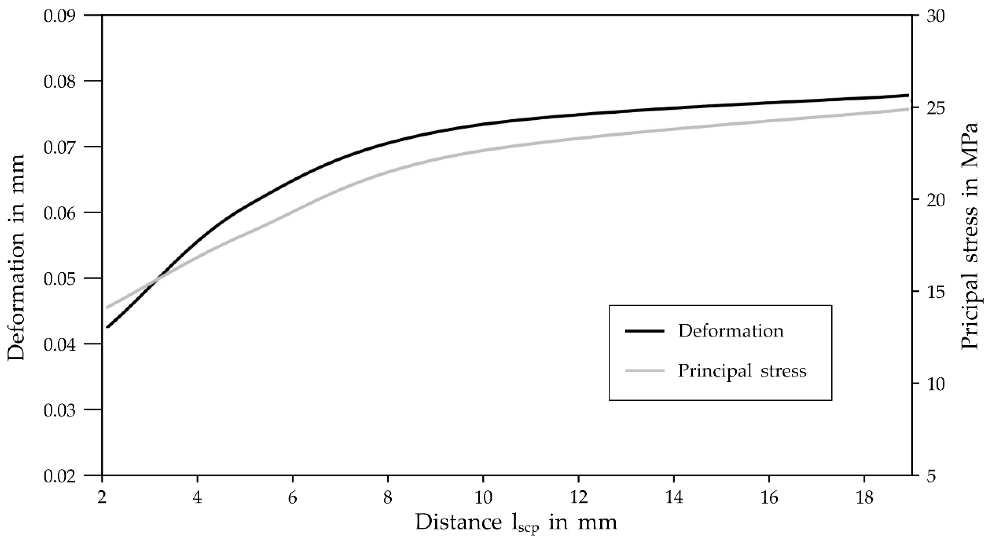
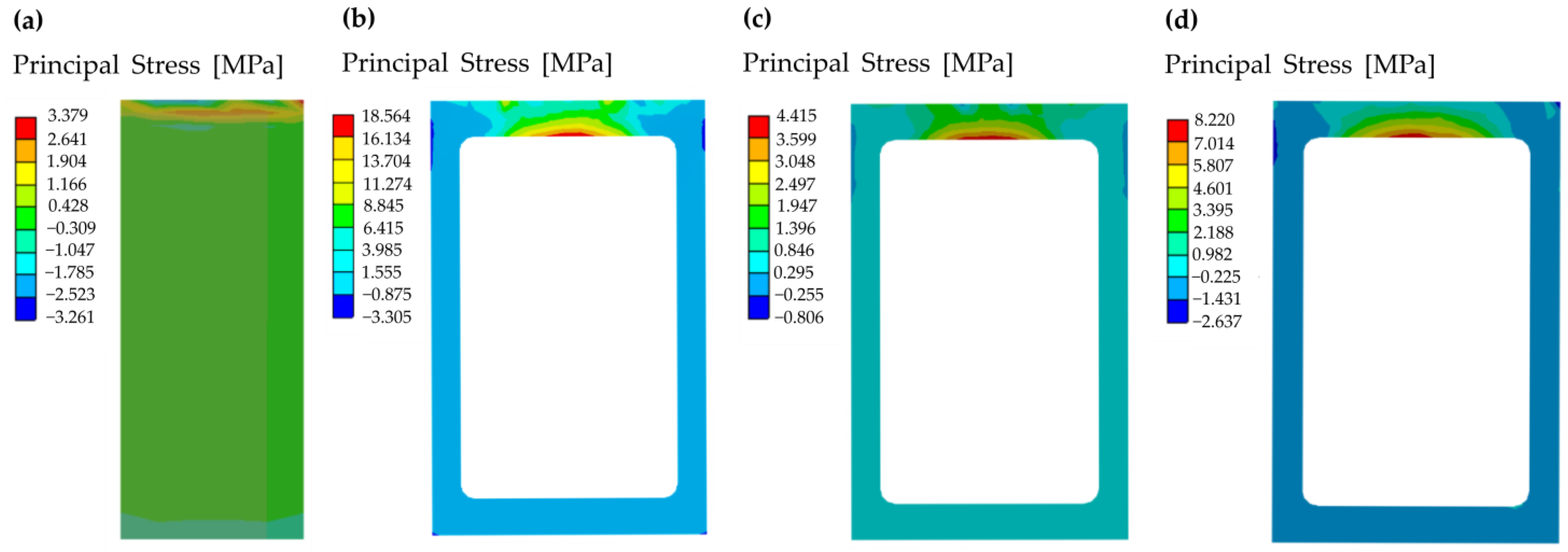
4.5. Results of the FEA
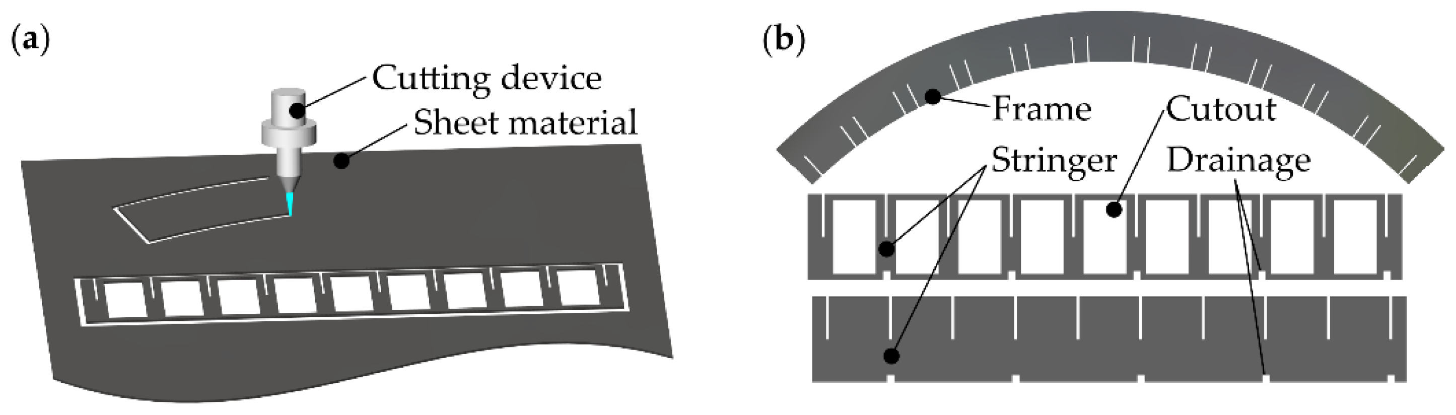
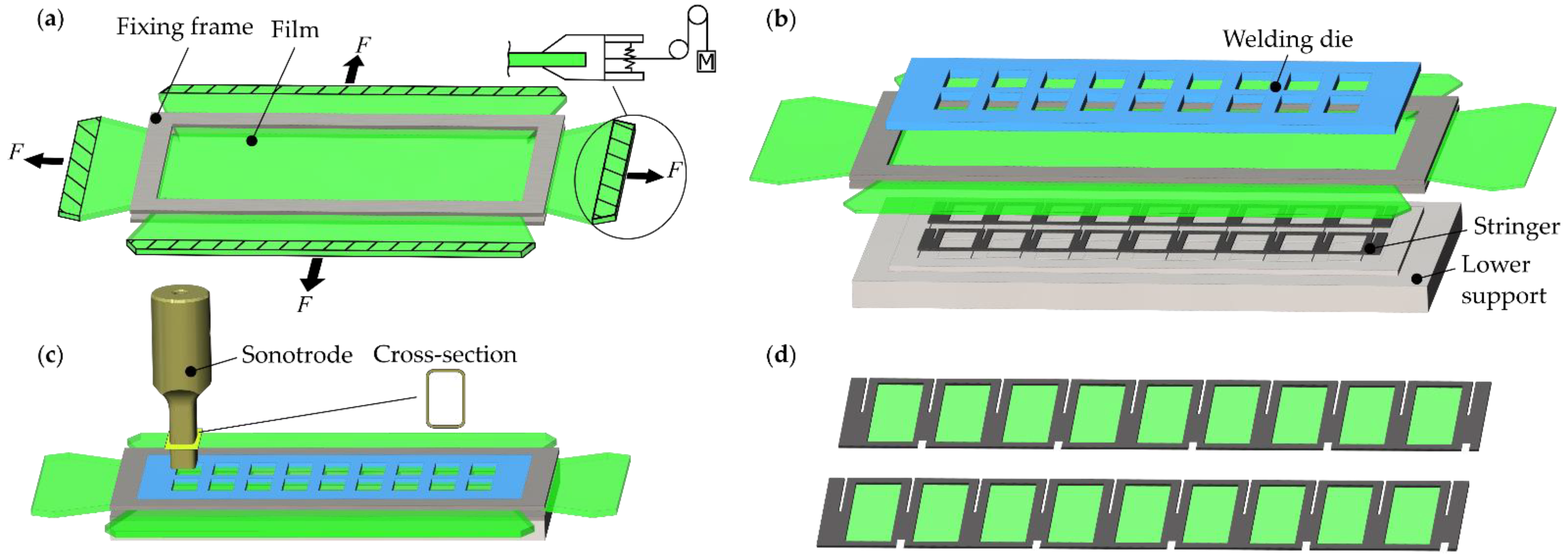
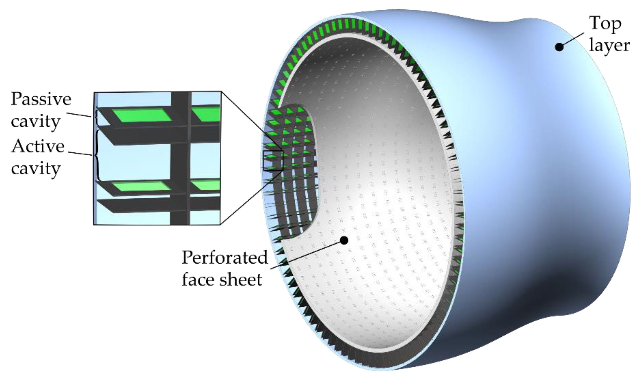
5. Design and Manufacturing Feasibility Study for Curved Acoustic Liners
5.1. Design and Manufacturing Concept HR-Liner
5.2. Design and Manufacturing Concept of Curved PR-Liner
6. Conclusions
6.1. Experimental Investigation
6.2. Models and Parameter Studies of FHR/PR Liner
6.3. Structural Mechanical Analysis
6.4. Design Concepts and Production
Author Contributions
Funding
Institutional Review Board Statement
Informed Consent Statement
Data Availability Statement
Conflicts of Interest
References
- Mi, Y.; Yu, X. Attenuation of low-frequency sound in U-shaped duct with membrane coupled acoustic resonator: Modeling and analysis. J. Sound Vib. 2020, 489, 115679. [Google Scholar] [CrossRef]
- Wu, D.; Zhang, N.; Mak, C.M.; Cai, C. Hybrid noise control using multiple Helmholtz resonator arrays. Appl. Acoust. 2019, 143, 31–37. [Google Scholar] [CrossRef]
- Jones, M.; Howerton, B.; Ayle, E. Evaluation of Parallel-Element, Variable-Impedance, Broadband Acoustic Liner Concepts. In Proceedings of the 18th AIAA/CEAS Aeroacoustics Conference (33rd AIAA Aeroacoustics Conference), Colorado Springs, CO, USA, 4–6 June 2012; American Institute of Aeronautics and Astronautics: Reston, VI, USA, 2012. ISBN 978-1-60086-932-7. [Google Scholar]
- Jones, M.G.; Nark, D.M.; Howerton, B.M. Impedance eduction for uniform and multizone acoustic liners. Int. J. Aeroacoustics 2021, 20, 458–477. [Google Scholar] [CrossRef]
- Dodge, C.; Zhang, Y.; Cattafesta, L.N.; Howerton, B.M.; Kreitzman, J.R. A Dielectric Elastomer Acoustic Liner. In Proceedings of the AIAA Aviation 2021 Forum, Virtual Event, 2–6 August 2021; American Institute of Aeronautics and Astronautics: Reston, VI, USA, 2021. ISBN 978-1-62410-610-1. [Google Scholar]
- Horowitz, S.B.; Sheplak, M.; Cattafesta, L.N.; Nishida, T. A MEMS acoustic energy harvester. J. Micromech. Microeng. 2006, 16, S174–S181. [Google Scholar] [CrossRef]
- De Bedout, J.M.; Franchek, M.A.; Bernhard, R.J.; Mongeau, L. Adaptive-passive noise control with self-tuning Helmholtz resonators. J. Sound Vib. 1997, 202, 109–123. [Google Scholar] [CrossRef]
- Hu, G.; Tang, L.; Cui, X. On the modelling of membrane-coupled Helmholtz resonator and its application in acous-tic metamaterial system. Mech. Syst. Signal Process. 2019, 132, 595–608. [Google Scholar] [CrossRef]
- Kohlenberg, F.; Schulz, A.; Enghardt, L.; Knobloch, K. Modelling of Acoustic Liners Consisting of Helmholtz Reso-nators Coupled with a Second Cavity by Flexible Walls. In Proceedings of the 28th AI-AA/CEAS Aeroacoustics 2022 Conference, Southampton, UK, 14–17 June 2022; American Institute of Aeronautics and Astronautics: Reston, VI, USA, 2022. ISBN 978-1-62410-664-4. [Google Scholar]
- Wang, C.; Cheng, L.; Huang, L. Realization of a broadband low-frequency plate silencer using sandwich plates. J. Sound Vib. 2008, 318, 792–808. [Google Scholar] [CrossRef]
- Liu, G.; Zhao, X.; Zhang, W.; Li, S. Study on plate silencer with general boundary conditions. J. Sound Vib. 2014, 333, 4881–4896. [Google Scholar] [CrossRef]
- Kisler, R.; Sarradj, E. Plate Silencers for Broadband Low Frequency Sound Attenuation. Acta Acust. United Acust. 2018, 104, 521–527. [Google Scholar] [CrossRef]
- Fuchs, H.V. Applied Acoustics: Concepts, Absorbers, and Silencers for Acoustical Comfort and Noise Control. Alternative Solutions-Innovative Tools-Practical Examples; Springer: Berlin/Heidelberg, Germany, 2013; ISBN 9783642293665. [Google Scholar]
- Huang, L. A theoretical study of duct noise control by flexible panels. J. Acoust. Soc. Am. 1999, 106, 1801–1809. [Google Scholar] [CrossRef]
- Huang, L. Broadband sound reflection by plates covering side-branch cavities in a duct. J. Acoust. Soc. Am. 2006, 119, 2628–2638. [Google Scholar] [CrossRef]
- Wang, C.; Huang, L. Analysis of absorption and reflection mechanisms in a three-dimensional plate silencer. J. Sound Vib. 2008, 313, 510–524. [Google Scholar] [CrossRef]
- Neubauer, M.; Schwaericke, F.; Radmann, V.; Sarradj, E.; Modler, N.; Dannemann, M. Material Selection Process for Acoustic and Vibration Applications Using the Example of a Plate Resonator. Materials 2022, 15, 2935. [Google Scholar] [CrossRef] [PubMed]
- Hähnel, F.; Wolf, K. Evaluation of the Material Properties of Resin-impregnate NOMEX® Paper as Basis for the Simulation of the Impact Behaviour of Honeycomb Sandwich. In Proceedings of the 3rd International Conference on Composite Testing and Model Identification, Porto, Portugal, 10 April 2006. [Google Scholar]
- Foo, C.C.; Chai, G.B.; Seah, L.K. Mechanical properties of Nomex material and Nomex honeycomb structure. Compos. Struct. 2007, 80, 588–594. [Google Scholar] [CrossRef]
- Seemann, R.; Krause, D. Analysis of Free Edge Stresses in Composite Laminates Using Higher Order Theories. Indian J. Mater. Sci. 2014, 2014, 15. [Google Scholar]
- Zhang, Y.; Liu, T.; Tizani, W. Experimental and numerical analysis of dynamic compressive response of Nomex honeycombs. Compos. Part B Eng. 2018, 148, 27–39. [Google Scholar] [CrossRef]
- Giglio, M.; Manes, A.; Gilioli, A. Investigations on sandwich core properties through an experimental–numerical approach. Compos. Part B Eng. 2012, 43, 361–374. [Google Scholar] [CrossRef]
- Liu, L.; Meng, P.; Wang, H.; Guan, Z. The flatwise compressive properties of Nomex honeycomb core with debond-ing imperfections in the double cell wall. Compos. Part B Eng. 2015, 76, 122–132. [Google Scholar] [CrossRef]
- Neubauer, M.; Dannemann, M.; Kucher, M.; Bleil, N.; Wollmann, T.; Modler, N. Numerical Buckling Analysis of Hybrid Honeycomb Cores for Advanced Helmholtz Resonator Liners. J. Compos. Sci. 2021, 5, 116. [Google Scholar] [CrossRef]
- Heimbs, S.; Middendorf, P.; Hampf, C.; Hähnel, F.; Wolf, K. Aircraft Sandwich Structures with Folded Core under Impact Load Porta (PRT). In Proceedings of the 8th International Conference on Sandwich Structures, ICSS8, Porto, Portugal, 6 May 2008; pp. 369–380. [Google Scholar]
- Wang, B.; Hu, J.; Li, Y.; Yao, Y.; Wang, S.; Ma, L. Mechanical properties and failure behavior of the sandwich struc-tures with carbon fiber-reinforced X-type lattice truss core. Compos. Struct. 2018, 185, 619–633. [Google Scholar] [CrossRef]
- Côté, F.; Russell, B.P.; Deshpande, V.S.; Fleck, N.A. The Through-Thickness Compressive Strength of a Composite Sandwich Panel with a Hierarchical Square Honeycomb Sandwich Core. J. Appl. Mech. 2009, 76, 061004. [Google Scholar] [CrossRef]
- Ma, X.; Su, Z. Development of acoustic liner in aero engine: A review. Sci. China Technol. Sci. 2020, 63, 2491–2504. [Google Scholar] [CrossRef]
- Pütz, M.; Lafont, U.; Wittlich, M.; Markestein, E.; Herrmann, C.; Fischer, H. 3D honeycomb for advanced manufacturing for space application. CEAS Space J. 2022, 1–9. [Google Scholar] [CrossRef]
- Zhao, Z.; Liu, C.; Wang, H.; Simon, J.-W.; Wang, J.; Li, Y. Crushing behavior of curved Nomex honeycombs under combined shear-compression loads. Int. J. Mech. Sci. 2022, 228, 107480. [Google Scholar] [CrossRef]
- Wadley, H.N.G. Multifunctional periodic cellular metals. Philos. Trans. A Math. Phys. Eng. Sci. 2006, 364, 31–68. [Google Scholar] [CrossRef] [PubMed]
- Dannemann, M.; Kucher, M.; Kunze, E.; Modler, N.; Knobloch, K.; Enghardt, L.; Sarradj, E.; Höschler, K. Experimental Study of Advanced Helmholtz Resonator Liners with Increased Acoustic Performance by Utilising Material Damping Effects. Appl. Sci. 2018, 8, 1923. [Google Scholar] [CrossRef]
- Dahiya, A.K.; Bhuyan, B.K.; Kumar, S. Perspective study of abrasive water jet machining of composites—A review. J. Mech. Sci. Technol. 2022, 36, 213–224. [Google Scholar] [CrossRef]
- Khan, M.A.; Soni, H.; Mashinini, P.M.; Uthayakumar, M. Abrasive water jet cutting process form machining metals and composites for engineering applications: A review. Eng. Res. Express 2021, 3, 22004. [Google Scholar] [CrossRef]
- Atul, S.T.; Babu, M.C.L. A review on effect of thinning, wrinkling and spring-back on deep drawing process. Proc. Inst. Mech. Eng. Part B J. Eng. Manuf. 2019, 233, 1011–1036. [Google Scholar] [CrossRef]
- Goergen, C.; Schommer, D.; Duhovic, M.; Mitschang, P. Deep drawing of organic sheets made of hybrid recycled carbon and thermoplastic polyamide 6 staple fiber yarns. J. Thermoplast. Compos. Mater. 2020, 33, 754–778. [Google Scholar] [CrossRef]
- Bhudolia, S.K.; Gohel, G.; Leong, K.F.; Islam, A. Advances in Ultrasonic Welding of Thermoplastic Composites: A Review. Materials 2020, 13, 1284. [Google Scholar] [CrossRef] [PubMed]
- Villegas, I.F. Ultrasonic Welding of Thermoplastic Composites. Front. Mater. 2019, 6, 291. [Google Scholar] [CrossRef]
- Liu, S.-J.; Chang, I.-T. Optimizing the Weld Strength of Ultrasonically Welded Nylon Composites. J. Compos. Mater. 2002, 36, 611–624. [Google Scholar] [CrossRef]
- Liu, S.-J.; Chang, I.-T.; Hung, S.-W. Factors affecting the joint strength of ultrasonically welded polypropylene composites. Polym. Compos. 2001, 22, 132–141. [Google Scholar] [CrossRef]
- Knobloch, K.; Enghardt, L.; Bake, F. Helmholtz Resonator Liner with Flexible Walls. In Proceedings of the 2018 AIAA/CEAS Aeroacoustics Conference, Atlanta, Georgia, 25–29 June 2018; American Institute of Aeronautics and Astronautics: Reston, VI, USA, 2018. ISBN 978-1-62410-560-9. [Google Scholar]
- Wang, C.; Han, J.; Huang, L. Optimization of a clamped plate silencer. J. Acoust. Soc. Am. 2007, 121, 949–960. [Google Scholar] [CrossRef] [PubMed]
- Wang, C. Development of a Broadband Silencer in Flow duct. Ph.D. Thesis, Hong Kong Polytechnic University, Hong Kong, China, 2008. [Google Scholar]
- Choy, Y.S.; Liu, Y.; Cheung, H.Y.; Xi, Q.; Lau, K.T. Development of composite plate for compact silencer design. J. Sound Vib. 2012, 331, 2348–2364. [Google Scholar] [CrossRef]
- Azimi, M.; Ommi, F.; Alashti, N.J. Using Acoustic Liner for Fan Noise Reduction in Modern Turbofan Engines. Int. J. Aeronaut. Space Sci. 2014, 15, 97–101. [Google Scholar] [CrossRef][Green Version]
- Özkaya, E.; Gauger, N.R.; Hay, J.A.; Thiele, F. Efficient Design Optimization of Acoustic Liners for Engine Noise Reduction. AIAA J. 2020, 58, 1140–1156. [Google Scholar] [CrossRef]
- Tsai, S.W.; Wu, E.M. A General Theory of Strength for Anisotropic Materials. J. Compos. Mater. 1971, 5, 58–80. [Google Scholar] [CrossRef]
- Hoeschler, K.; Sarradj, E.; Modler, N.; Enghardt, L. Novel Jet Engine Acoustic Liner with Improved Broadband Noise Absorption. In Proceedings of the 31st Congress of the International Council of the Aeronautical Sciences, ICAS 2018, Belo Horizonte, Brazil, 9–14 September 2018; International Council of The Aeronautical Sciences (ICAS): Bonn, Germany, 2018. ISBN 978-393218288-4. [Google Scholar]
- Gherissi, A.; Abbassi, F.; Ammar, A.; Zghal, A. Numerical and Experimental Investigations on Deep Drawing of G1151 Carbon Fiber Woven Composites. Appl. Compos. Mater. 2016, 23, 461–476. [Google Scholar] [CrossRef]
- Mechel, F.P. Schallabsorber Band II: Innere Schallfelder—Strukturen; S. Hirzel: Stuttgart/Leipzig, Germany, 1995; ISBN 978-3-7776-0572-2. [Google Scholar]
- Schirmer, W. Technischer Lärmschutz; Springer: Berlin/Heidelberg, Germany, 2006; ISBN 978-3-540-25507-9. [Google Scholar]
- Britzke, M. Verfahren zur automatisierten Fertigung rahmenloser Sandwichplatten mit Papierwabenkern. Light Des. 2009, 2, 55–62. [Google Scholar] [CrossRef]


| Thickness mm | Aluminum (Alu) 70,000 MPa | Poly Propylene (PP) 1600 MPa | Thermoplastic Polyurethan (TPU) 16 MPa | Polyamide 6 (PA6) 800 MPa | Polyphenylene Sulphide (PPS) 2400 MPa | Polyether Ether Ketone (PEEK) 2800 MPa |
|---|---|---|---|---|---|---|
| 0.001 | x | |||||
| 0.01 | x | x | x | x | x | |
| 0.02 | x | |||||
| 0.03 | x | |||||
| 0.04 | x |
| Parameter | Symbol | Unit | Value, Value Range | Design Point |
|---|---|---|---|---|
| Common parameters for both concepts | ||||
| Duct height | mm | 60 | 60 | |
| Duct width | mm | |||
| Young’s modulus | MPa | |||
| Poisson ratio | - | |||
| Loss factor | - | |||
| Density | kg/m3 | |||
| Plate thickness | mm | 0.3 | ||
| FHR specific parameters | ||||
| Plate diameter | mm | 15 | ||
| Cell cross Section | mm2 | |||
| Face sheet porosity | - | 2.6% | 2.6% | |
| Face sheet thickness | mm | 2 | 2 | |
| Main cavity height | mm | 40 | 40 | |
| Second cavity height | mm | 10 | ||
| Liner length | mm | 200 | ||
| PR specific parameters | ||||
| Cavity length | mm | 65 | ||
| Cavity height | mm | 30 | ||
| Cavity width | mm | |||
| Component | Face Sheet | Core | Back Plate | Cell Geometry | Mass [kg] | ||
|---|---|---|---|---|---|---|---|
| HR liner | 2/2 Twill Weave * CFRP (0.2 mm) | Aramid Paper (Nomex) (0.194 mm) | 10 UD-plies CFRP Orientation: (1 mm) | 2 UD-plies GFRP Orientation: ] (0.2 mm) | Honeycomb | 0.218 | |
| FHR-Type 1 | Square Cells | 0.240 | |||||
| FHR-Type 2 | PA6-GF–2/2 Twill Weave (1 mm) | PA6-GF–2/2 Twill Weave (1 mm) | PA6-GF–2/2 Twill Weave (1 mm) | PA6-GF–2/2 Twill Weave (1 mm) | Square Cells | 0.573 | |
| Material | Nomex with Phenolic Resin | PVC-Rigid Foam Core | Carbon Fiber with Epoxy Resin–Unidirectional- (Woven Fabric) | PA6-GF E-Glass | Glass Fiber with Epoxy Resin |
|---|---|---|---|---|---|
| Youngs Modulus [MPa] | 6034 | 70 | 129,000 (61,000) | 18,000 | 29,700 |
| Youngs Modulus [MPa] | 5263 | 70 | 7380 (61,000) | 18,000 | 29,700 |
| Youngs Modulus [MPa] | 4427 | 70 | 7380 (6900) | 22,000 | 8600 |
| Poisson’s ratio | 0.316 | 0.3 | 0.319 (0.04) | 0.17 | 0.17 |
| Poisson’s ratio | 0.327 | 0.3 | 0.319 (0.3) | 0.17 | 0.17 |
| Poisson’s ratio | 0.317 | 0.3 | 0.4 (0.3) | 0.49 | 0.17 |
| Shear Modulus [MPa] | 2142 | 27 | 4480 (3300) | 7692 | 5300 |
| Shear Modulus [MPa] | 1588 | 27 | 4480 (2700) | 7692 | 3070 |
| Shear Modulus [MPa] | 1865 | 27 | 2636 (2700) | 7382 | 3070 |
| Density [] | 1185 | 60 | 1560 (1420) | 1800 | 2200 |
| Fiber processing type | - | - | Unidirectional (Twill Weave 2/2) | Twill 2/2 | Twill 2/2 |
| Stress limits | |||||
| Tensile Strength [MPa] | 62.3 | 1.5 | 2553 (805) | 380 | 367 |
| Tensile Strength [MPa] | 48.2 | 1.5 | 42 (805) | 380 | 367 |
| Tensile Strength [MPa] | 48.2 | 1.5 | 42 (50) | - | 128 |
| Compression Strength [MPa] | −85 | 0.96 | 1239 (509) | - | 549 |
| Compression Strength [MPa] | −78 | 0.96 | 199 (509) | - | 549 |
| Compression Strength [MPa] | −78 | 0.96 | 199 (170) | - | 39 |
| Shear strength [MPa] | 71.8 | 0.93 | 138 (125) | 64 | 97 |
| Shear strength [MPa] | 71.8 | 0.93 | 138 (65) | 64 | 97 |
| Shear strength [MPa] | 71.8 | 0.93 | 138 (65) | 64 | 97 |
Disclaimer/Publisher’s Note: The statements, opinions and data contained in all publications are solely those of the individual author(s) and contributor(s) and not of MDPI and/or the editor(s). MDPI and/or the editor(s) disclaim responsibility for any injury to people or property resulting from any ideas, methods, instructions or products referred to in the content. |
© 2022 by the authors. Licensee MDPI, Basel, Switzerland. This article is an open access article distributed under the terms and conditions of the Creative Commons Attribution (CC BY) license (https://creativecommons.org/licenses/by/4.0/).
Share and Cite
Neubauer, M.; Genßler, J.; Radmann, V.; Kohlenberg, F.; Pohl, M.; Böhme, K.; Knobloch, K.; Sarradj, E.; Höschler, K.; Modler, N.; et al. Experimental and Numerical Investigation of Novel Acoustic Liners and Their Design for Aero-Engine Applications. Aerospace 2023, 10, 5. https://doi.org/10.3390/aerospace10010005
Neubauer M, Genßler J, Radmann V, Kohlenberg F, Pohl M, Böhme K, Knobloch K, Sarradj E, Höschler K, Modler N, et al. Experimental and Numerical Investigation of Novel Acoustic Liners and Their Design for Aero-Engine Applications. Aerospace. 2023; 10(1):5. https://doi.org/10.3390/aerospace10010005
Chicago/Turabian StyleNeubauer, Moritz, Julia Genßler, Vincent Radmann, Fleming Kohlenberg, Michael Pohl, Kurt Böhme, Karsten Knobloch, Ennes Sarradj, Klaus Höschler, Niels Modler, and et al. 2023. "Experimental and Numerical Investigation of Novel Acoustic Liners and Their Design for Aero-Engine Applications" Aerospace 10, no. 1: 5. https://doi.org/10.3390/aerospace10010005
APA StyleNeubauer, M., Genßler, J., Radmann, V., Kohlenberg, F., Pohl, M., Böhme, K., Knobloch, K., Sarradj, E., Höschler, K., Modler, N., & Enghardt, L. (2023). Experimental and Numerical Investigation of Novel Acoustic Liners and Their Design for Aero-Engine Applications. Aerospace, 10(1), 5. https://doi.org/10.3390/aerospace10010005