Abstract
Strict regulations issued by international administrative bodies limit the CO2 equivalent emissions for new aircraft, while increasing efficiency requirements. To reach this goal, next generations of aircraft will use more electrical power than their predecessors, so distribution voltage levels will inevitably increase to limit the weight of the electrical wiring interconnect system (EWIS). However, such increased voltage levels generate higher electric stresses in insulation materials as well as in electric and electronic components; thus new failure modes triggered by electrical discharges will appear, their effects being aggravated by harsh environments typical of aircraft systems. The combined effect of higher electrical stresses, compact designs, and low-pressure operating conditions greatly intensifies the risks of premature insulation failure due to electrical discharge activity. This paper shows that by using image sensors, it is possible to detect, localize, and quantify the intensity of electrical discharges occurring in aircraft environments. Through experiments carried out in a low-pressure chamber using an image sensor, this work detects and determines the intensity of electrical discharges generated in electrical wires in their initial stage, long before major faults develop. This paper also shows that the intensity of the discharges calculated from the digital images obtained with the image sensor is directly proportional to the electrical energy involved in the discharge process and increases linearly with the applied voltage. Due to the difficulty of detecting these failure modes at a very early stage, this strategy could potentially facilitate predictive maintenance tasks while contributing to increased levels of aircraft safety.
1. Introduction
Strict regulations issued by the International Civil Aviation Organization (ICAO) [1] and other administrative bodies limit and reduce CO2 equivalent emissions for new aircraft, while increasing efficiency requirements. Therefore, future aircraft will have greater efficiency, less environmental impact, and lower fuel consumption. Therefore, the aircraft of the future will have greater efficiency, lower environmental impact, and lower fuel consumption. Another important objective is to facilitate maintenance tasks by increasing safety levels [2]. Therefore, future aircraft must be more electric, so the more electric aircraft (MEA) has emerged as an alternative and a transition to the all-electric aircraft (AEA). Due to increased electric power demand from MEA and AEA aircraft, in order to limit the weight of the electrical wiring interconnect system (EWIS), distribution voltage levels will increase [3]. However, increased voltage levels will generate higher electric stresses in insulation materials and in electric and electronic components, thus producing new failure modes. The forecast indicates that future generations of aircraft could operate with voltages in the range of 1 kV [4] to 4.5 kV [5]. Unpressured areas of commercial jetliners must withstand ambient pressures in the approximate range of 100–10 kPa [6], so the pressure at maximum altitude can be as low as 10% of the pressure at sea level, thus favoring the inception of electrical discharges since the dielectric strength of the air is greatly reduced with pressure [6,7]. Commercial aircraft flight altitudes are in the range of 9.5–11.5 km with a maximum height of around 15 km [8], although military aircraft can fly higher. Therefore, nonpressurized aircraft compartments must withstand pressures in the range of 100–10 kPa, that is, 100%–10% of sea-level atmospheric pressure, respectively, and extreme environmental conditions [9], which, together with higher operating voltages and compact designs, affect the behavior of wiring insulation materials [10,11]. Therefore, during cruising, wiring systems, electric circuits, and electronic components found in nonpressurized areas are more prone to the damaging effects of electrical discharges [10,12] compared with ground-level operation [11], because discharge activity increases at lower pressure [13].
This higher electric stress, combined with the harsh environmental conditions (particularly the low-pressure environment) and the high compactness characteristic of aircraft systems, will result in higher electrical stresses in aircraft insulation materials and systems. These conditions increase the probability and intensity of different types of electrical discharges [14]. Common types of electrical discharges in insulation systems include surface discharges, arc tracking, arcing, and finally electric arcs. Electrical discharges produce measurable effects, such as acoustic and electromagnetic noise, visible light and ultraviolet (UV) emissions, current pulses, diverse types of chemicals, and heating.
Partial discharges (PDs) are a type of electrical discharges that develop between two electrodes separated by an insulating medium (either gaseous, liquid, or solid) when the dielectric strength of the insulation is exceeded by the local electric field. Their effects are constrained to the vicinity of the electrodes, so they do not completely bridge the insulation pathway between the electrodes [15]. When dealing with gaseous insulation media, PDs are known as corona, which are radiant discharges that occur under the effect of inhomogeneous electric fields [16] that exceed a critical threshold value [17,18].
As indicated by the IEC 60112:2020 standard [19], the tracking activity produces a progressive growth of conductive tracks or paths on the surface or even inside a solid insulating medium due to the joint effect of high electric stresses and electrolytic contamination. The continuous effect of the electrical discharges on polymeric insulation systems over time produces chemical modifications due to the flow of electrons at the discharge sites [20], increasing their temperature, gradually degrading insulation materials, and increasing the risk of discharge occurrence. Although not very damaging in the short term, in the long term, the cumulative chemical changes due to the bombardment of PD-released electrons [20] will eventually produce major faults [21] as they generate conductive paths or tracks on the surface of the polymeric material. These tracks tend to favor the circulation of an electric current, which increases the temperature in the conductive path, further damaging the insulation, weakening the insulating material, and promoting arcing activity [22] between adjacent wires. The successive electrical discharges widen the existing tracks, causing arc tracking [21], spreading the damaged area with the consequent risk of fire [23]. When initiated on insulated wires, arc tracking first generates low-magnitude surface discharges that pyrolyze the insulating material and create partly conducting paths. These paths, in turn, promote low-magnitude intermittent surface discharges that increase the temperature and further damage the insulation [24]. Given that in the early stage the energy associated with arc tracking discharges is very low, its early detection is very complex [25], being an unsolved problem.
Aircraft maintenance is strictly regulated by international standards to ensure proper and safe flight operation. However, maintenance costs are highly dependent on aircraft technology. Due to the greater ease of measuring electric signals, MEA and AEA aircraft allow maintenance tasks to be simplified and costs to be reduced due to the replacement of hydraulic and pneumatic systems with electrical systems. Today’s wide-body airliners have many kilometers of wires, complex wiring harnesses, and thousands of different components, such as terminations, clamps, or connectors, often placed inside ducts, conduits, or troughs [26], which makes fault detection and maintenance tasks difficult. Due to the low energy involved in electrical discharges in their initial stage, their effects remain undetected by onboard protections, although their continuous effect tends to damage wiring insulation [27], eventually causing major faults [28] if corrective actions are not applied. To this end, the selection of suitable insulating materials combined with improved wiring harness layout designs and the application of a plan for discharge monitoring can reduce the occurrence and severity of discharges because remedial actions can be applied well in advance of the development of critical faults [29].
It is well known that, at an early stage, surface discharges that occur in wiring insulation systems generate UV and visible light. Therefore, the use of imaging sensors to detect, locate, and quantify the intensity of such discharges is advantageous over other conventional methods due to the noisy environments where the wiring systems are placed and the relative immunity of optical sensors to electromagnetic and acoustic noise, where conventional electromagnetic or acoustic methods for discharge detection would fail [30,31]. This paper contributes in this area, since surface discharges that occur in the insulation of electric wires are detected, located, and their intensity estimated using image sensors. The estimation of the intensity of the discharges and their temporal evolution opens a new field for the development of state of health and remaining useful life approaches, which could be potentially applied in predictive maintenance strategies. This is an open field that requires more study and experimental works.
This work focuses on the optical detection, location, and quantification of the intensity of surface discharges in their early stage produced in insulated wires operating under aeronautic pressure conditions. This is a new approach, since due to the low initial energy of such discharges, they remain undetected when conventional electrical protections are used. The discharges are detected, located, and quantified using a low-cost imaging sensor that is sensitive to visible light and partially sensitive to the near UV spectrum. To validate the effectiveness and accuracy of the proposed approach, the behavior of aeronautic ETFE insulated wires is studied in the 100–10 kPa range under alternating current supply in the frequency range of 50–800 Hz. This frequency range was selected to cover 50 Hz power grid frequency, 400 Hz constant frequency, and 320–800 Hz wide frequency currently in use in aircraft systems [26]. This new approach makes it possible to detect and locate discharge sites at a very early stage, as well as determine their intensity, which can be very useful in facilitating maintenance tasks and increasing the safety levels of next-generation aircraft. Although this paper is focused on monitoring electrical discharges in aeronautical wires, the methods proposed here can be applied to other applications where electrical discharges occur, such as transmission lines and electrical substations installed in high-altitude regions or plasma surface treatments, among others.
This research paper is organized as follows: Section 2 details the applied image processing approach for determining the intensity of the digital images of the discharges, which is directly related to their electrical energy, as shown in Section 4. Section 3 describes the experimental setup including the analyzed ETFE notched wires used to carry out the experiments. Section 4 summarizes the experimental results obtained in a low-pressure chamber and discusses the results obtained, and finally, Section 5 concludes this document.
2. Image Processing Approach
This section describes the approach applied to determine the intensity or magnitude of the discharges directly from the information provided by the digital images. The digital images of the discharges analyzed in this paper are acquired using a conventional digital imaging sensor, and the intensity of the discharges is calculated by appropriate processing of such images. This section also shows that the intensity of the images obtained using this approach is directly related to the electrical energy involved in the discharges so that the intensity of the discharges is a reliable indicator of the severity or magnitude of the insulation faults, which has enormous potential for predictive maintenance approaches.
Image sensors are sensitive to the optical emission generated by the discharge process [32], so they are increasingly applied to detect the electrical discharges [2]. Light photons are released as a consequence of the different electron transitions generated by the discharge process, such as electronic excitation, recombination, or ionization [33]. Since commercially available image sensors are composed of an array of tiny photodiodes, they allow not only for locating discharge sites but also for quantifying their intensity, which is essential for the safe, reliable, and stable operation of aircraft power systems [34]. Different works have shown that digital images allow the detection and localization of discharge sites in samples of polymeric insulating samples [35,36,37]. Other works have revealed that the energy dissipated by the electrical discharges is correlated with the number of photons generated during the discharge process and, therefore, with the intensity of the images obtained with digital cameras [2,34,38,39]. However, none of these works study the discharge behavior of aeronautical wires, so this paper contributes to this field.
2.1. Normalized Intensity of the Discharges Obtained from the Digital Images
Digital RGB images IRGB acquired by image sensors can be assumed to be a matrix of m × n pixels. To obtain the intensity of the discharges, the RGB image is first converted to a grayscale image. Next, the intensity of the discharge is calculated within a window that includes the discharge. The effect of background noise is minimized by taking a second window of the same size, containing only background noise. Next, the pixels in the second window are subtracted from the pixels in the first window, as shown in Figure 1.
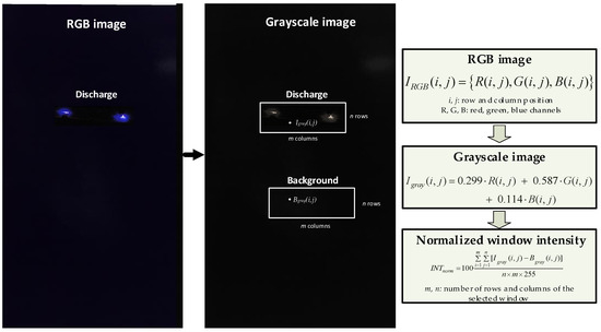
Figure 1.
Calculation process of the normalized intensity of the discharges obtained from digital RGB images.
It should be noted that the discharge sites are located directly from the digital images, and their intensity is determined from (1), as shown in Figure 1:
where Igray(i,j) is the grayscale intensity of the (i,j) coordinate of a window of dimensions m × n centered in the image of the discharge, while Bgray(i,j) is the grayscale intensity of the (i,j) coordinate of a window of the same dimensions capturing the background of the image, as shown in Figure 1.
2.2. Electrical Power due to the Discharges
It is well known that the apparent electrical power can be calculated as
IRMS and VRMS being the root mean square (RMS) values of the current and voltage, respectively.
The discharges have a very short duration, in the order of fractions of microseconds, generating high-frequency components. Electrical discharges occur at different locations on the voltage waveform, so all discharges have their own voltage, which is not constant throughout the life of the discharge. Due to their low amplitude, discharges are better detected by analyzing the current waveform than the voltage waveform. Therefore, care must be taken when calculating Equation (2), as shown in Figure 2. It is important to note that to determine whether or not a discharge occurs, a threshold value of 1.2 times the maximum amplitude of the background noise acquired by the current probe was selected.
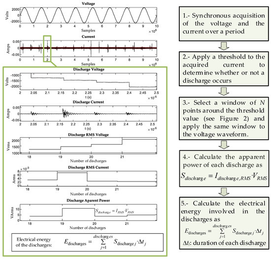
Figure 2.
Calculation approach to determine the energy involved in the discharges.
Finally, as explained in Figure 2, the electrical energy of the discharges in one period of the power supply is determined as
where Sdischarg j is described in Figure 2 and Δtj is the duration of each discharge.
It is important to note that one full acquisition consists of 10 million samples spaced at 2 ns steps, resulting in a 20 ms acquisition. Regardless of the frequency of the waveform, the duration of the acquisitions is the same for all the experiments. This allows a direct comparison between electrical energy and image intensity, given that image acquisitions have a constant duration of 32 s for all experiments.
Discharge pulses are very fast, lasting a few fractions of a microsecond. Therefore, in 20 ms (corresponding to 8 complete periods at 400 Hz), a large number of discharges can occur, depending on the applied voltage. To capture the full discharge pattern, the discharge pulses must be acquired very fast (time steps of 2 ns in this work), so the average energy of the discharges is obtained in a time period of 20 ms. However, the image sensor is much slower (not as sensitive) as it needs to capture a sufficient number of photons. Therefore, 32 s long exposure photographs were taken.
In Section 4, it is shown that the normalized intensity of the images is directly proportional to the square root of the electrical energy involved in the discharges since the sensitive elements of the image sensors produce an electrical response proportional to the amplitude of the incident light wave. This is because the amplitude of the signal detected by any individual sensitive element of the image sensor is directly related to the amplitude of the optical radiation propagating over the sensor, while the energy is proportional to the square of the amplitude.
3. Experimental Setup
This section details the aeronautic ETFE insulated wire samples used to experimentally validate the behavior and accuracy of the surface discharge detection, location, and quantification method described in Section 2. It also describes the instrumentation used to detect, locate, and quantify the intensity of the discharges.
3.1. Analyzed Intentionally Damaged Insulated Wires
It should be noted that the wire electrodes discussed in this section attempt to emulate the surface discharges that occur in real aircraft environments under laboratory conditions at an early stage, when they are of very low energy, long before appreciable insulation damage is produced.
The insulated wires analyzed in this paper were intentionally damaged according to the practice described in the European standard EN 3475-603:2018 [40]. They comprise two parallel insulated wires. While one wire is connected directly to the high-voltage electrode, the other wire is connected to the ground. Each wire is about 0.5 m long, and the insulation layers of both cables were intentionally damaged. To this end, the insulation layer was cut all the way around the circumference, so that 1 mm of insulation length was removed, as shown in Figure 3. To produce regular cuts in the insulation layer, that is, to artificially damage the studied wires, a wire-stripping tool (KNIPEX ErgoStrip, Wuppertal, Germany) was used. Lacing tapes are used to subject the mating wires, while ensuring they are straight and parallel and have continuous contact throughout the test area. The wires were cleaned with a cloth soaked in isopropyl alcohol before testing.
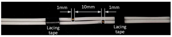
Figure 3.
ETFE-insulated pair of wire samples used to analyze the inception of the partial discharges.
Insulation materials for aircraft wires must be carefully selected to minimize arc tracking activity. Ethylene tetrafluoroethylene (ETFE) is among the most used insulation materials in aircraft wires [41]. Although applied in the past, insulation materials such as polyimide (Kapton®) are no longer used in new aircraft models due to the chemical changes they undergo when exposed to the combined effect of mechanical stress, heat, and moisture [41,42]. PVC is not used in aircraft wires due to the known problems related to dry arc tracking [43].
This work deals with AWG 24 ETFE insulated wire samples, whose properties are shown in Table 1.

Table 1.
Properties of the studied extruded ETFE insulated wire samples.
3.2. The Low-Pressure Chamber
Aeronautical pressure conditions are emulated by means of a low-pressure chamber formed by a cylindrical stainless steel vessel (height = 375 mm and diameter = 260 mm). It is sealed with a methacrylate lid that allows wireless communication to wirelessly transfer the digital images of the discharges to an external computer. The pressure is automatically regulated using a vacuum pump (2BA, 1/5 HP, 4.2 CFM, Bacoeng, Suzhou, China) and a P11-50KF0G4P digital pressure sensor (range: −100–0 kPa, precision: 1% FS, NEMSR, China). The three elements are connected in a closed control loop.
3.3. The Electrical Instrumentation Used
To determine the electrical energy of the discharges, the voltage and discharge current waveforms were acquired synchronously by means of a high-performance oscilloscope (MDO3024, 200 MHz, 2.5 Gsamples/s, Tektronix, Beaverton, OR, USA). Each oscilloscope acquisition consists of 10 Msamples per channel, recorded over a 20 ms period at a sampling rate of 0.5 Gsamples/s. As shown in Figure 2, the discharges can be seen as rapid oscillations in the current waveform with a total duration of around 1 μs.
Figure 4 shows a flow diagram of the measurements carried out to acquire the discharges.
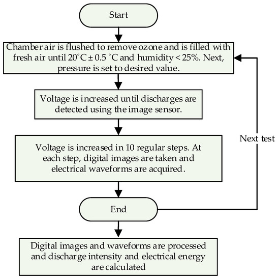
Figure 4.
Flow diagram of the experimental measurements.
Figure 5 shows a sketch of the experimental setup used to acquire the discharges.
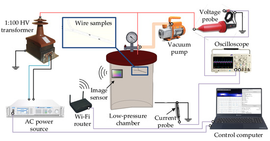
Figure 5.
Sketch of the experimental setup.
Variable frequency high-voltage was generated by connecting a programmable ac source (SP300VAC600W, 15–1000 Hz, 0–300 V, ±0.1 V, APM Technologies, Dongguan, China) to a single-phase transformer (VKPE-36, 1:100, 36 kV, Laboratorio Electrotécnico, Cornellà de Llobregat, Spain). The voltage was measured using a high-voltage probe (CT4028, 0–39 kVpeak, 1000:1, accuracy better than 3%, dc to 220 MHz, Cal Test Electronics, Yorba Linda, CA, USA).
The current was measured by means of a current probe (TCP0030A, dc to 120 MHz, accuracy of 1 mA, Tektronix, Beaverton, OR, USA), which was placed around the ground the wire to detect the discharge current flowing from the high-voltage electrode to the ground.
Digital images were acquired using a back-illuminated CMOS image sensor (IMX586, sensor size of 8.0 mm, cell size of 0.8 μm × 0.8 μm, 48 Mpixels, 30 frames/s, lens focus of 17.9 mm, Quad Bayer filter array, raw format, Sony, Tokyo, Japan), taking 32 s long exposure photographs. This sensor is sensitive to visible and near UV light [44].
4. Experimental Results
This section summarizes the electrical measurements and the experimental results obtained with the IMX586 back-illuminated CMOS image sensor.
4.1. Digital Images of the Discharges
To measure the intensity of the discharges, long-exposure photographs of 32 s were taken inside the low-pressure chamber. Figure 6 shows some of the digital images acquired under different conditions of voltage, pressure, and electrical frequency as well as the currents and voltages acquired by the oscilloscope. From the images, it can be deduced that higher frequencies produce more intense light emissions for similar conditions of voltage and pressure, even in an incipient state. Regarding the effect of pressure, it can be seen that compared with higher pressure, at lower pressure, the intensity of the discharges increases faster with increasing voltage levels. From the digital images, it is evident that the electric field is stronger around the notches intentionally made in the insulation layer of the wires, resulting in a higher discharge activity.
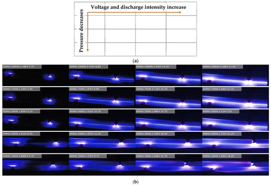
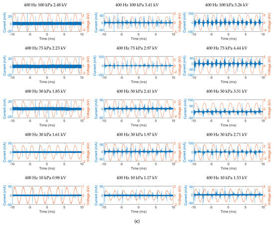
Figure 6.
ETFE aeronautic wires. (a) Trends of the graphs shown in (b). (a) Long-exposure digital images of the surface discharges under the experimental conditions described in each image (frequency, pressure, voltage in peak values, and the normalized intensity of the image). (c) Oscilloscope captions of the discharges.
4.2. Results Obtained with ETFE Samples
Figure 7 summarizes the results of the square root of the electrical energy involved in the discharges, whose values were calculated by processing the voltage and current waveforms due to the discharges following the procedure detailed in Section 2.2. From the results presented in Figure 7, it can be seen that the square root of the electrical energy of the discharges increases linearly with the applied voltage, so they show that discharge activity increases with the applied voltage. It is also deduced that the rate at which the square root of the electrical energy increases with voltage is nearly constant for a given frequency, regardless of the applied pressure. Results presented in Figure 7 also show that for a given applied voltage, discharge activity increases when reducing the pressure. They also show that the minimum voltage at which discharge activity is detected decreases with the ambient pressure.
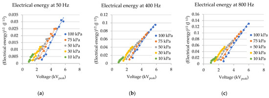
Figure 7.
Experimental results of the ETFE aeronautic wires. Square root of the electrical energy versus voltage for air pressures ranging from 10 to 100 kPa. (a) 50 Hz, (b) 400 Hz, (c) 800 Hz.
Figure 8 summarizes the results of the normalized intensity of the discharges, whose values were obtained from the digital images generated by the image sensor after a suitable postprocessing described in Section 2.1. The results presented in Figure 8 clearly show that the normalized intensity of the discharges increases linearly with the applied voltage. Results presented in Figure 8 also show that for a given applied voltage, discharge intensity detected by the image sensor increases when reducing the pressure. They also show that the minimum voltage at which discharge activity is detected by the image sensor decreases with the ambient pressure.
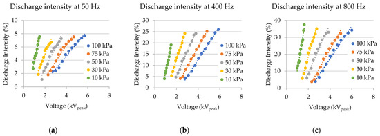
Figure 8.
Experimental results of the ETFE aeronautic wires. Normalized discharge intensity versus voltage for air pressures ranging from 10 to 100 kPa. (a) 50 Hz, (b) 400 Hz, (c) 800 Hz.
Table 2 summarizes the main parameters of the linear regression between the square root of the electrical energy of the discharges versus the applied voltage and the normalized image intensity versus the applied voltage. The high values of the coefficient of determination of these regressions show the linearity between Edischarges1/2–V and INTnorm–V. Thus, one can conclude that the square root of the energy of the discharges and the intensity of the digital images are related.
Table 2.
Main parameters of the linear regression y = ax + b between the electrical energy of the discharges versus the applied voltage and the normalized image intensity versus the applied voltage.
Figure 9 shows the values of the normalized intensity of the discharges versus the square root of the electrical energy for different pressures in the range of 100–10 kPa and for frequencies of 50, 400 Hz, 800 Hz. The linearity between both magnitudes is noted, thus proving that the normalized intensity of the discharges is proportional to the square root of the electrical energy of the discharges. These results suggest that the number of photons generated by the discharge activity is directly related to the energy of the discharges, so the intensity of the discharges calculated from the digital images can be used as a reliable indicator to quantify the severity of the discharges.
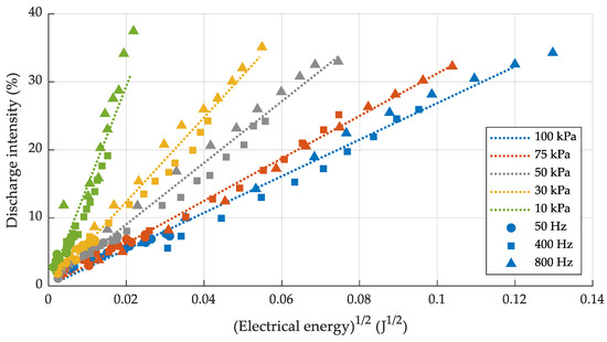
Figure 9.
Normalized intensity versus the electrical energy of the discharges for air pressures ranging from 10 to 100 kPa and at 50, 400, and 800 Hz frequencies.
Table 3 summarizes the main parameters of the linear regression between the normalized intensity of the discharges and the square root of the electrical energy for the different pressures analyzed in the range of 100–10 kPa. The results presented in Table 3 show the linearity between both magnitudes as deduced from the high values of the determination coefficient R2.
Table 3.
Main parameters of the linear regression y = ax + b between the normalized intensity and the square root of the electrical energy of the discharges for ETFE insulated wires.
5. Conclusions
The new aircraft designs are more electrified than the predecessors due to the strict regulations issued by different international agencies that limit the CO2 equivalent emissions in the new models. The use of more electrical energy implies an increase in the distribution voltage levels to limit the weight of the electrical wiring systems, thus increasing the electrical stress on the insulation materials, which together with the low pressures typical of aeronautical environments favor the development of electrical discharges. However, in their early stage, electrical discharges that occur in wiring systems often go unnoticed due to their low intensity and because wiring systems are often placed in inaccessible aircraft areas, such as ducts, conduits, or troughs. These difficulties make fault detection and maintenance tasks extremely difficult. This paper proposes an experimental approach to detect, locate, and quantify the intensity of electrical discharges that occur in wiring systems in the incipient stage using digital image sensors. To this end, a large set of tests was carried out in a low-pressure chamber to emulate the pressure found in unpressurized areas of aircraft. The tests were conducted using ETFE insulated wires. The results presented in this paper confirm that the intensity of the discharges calculated from digital images acquired with a conventional image sensor allows for detecting, locating, and quantifying the energy involved in the discharge process in the early stage long before major failures develop. The results presented also show that the intensity of the discharges determined from the digital images obtained with the image sensor is directly proportional to the electrical energy involved in the discharge process and increases linearly with the applied voltage. This approach could potentially ease predictive maintenance tasks while helping to increase aircraft safety levels.
Author Contributions
Conceptualization, P.B.-C. and J.-R.R.; methodology, J.-R.R.; software, J.-R.R. and P.B.-C.; validation, P.B.-C., J.-R.R. and J.A.O.; formal analysis, J.-R.R.; investigation, P.B.-C. and J.-R.R.; resources, J.-R.R. and J.A.O.; writing—original draft preparation, P.B.-C. and J.-R.R.; writing—review and editing, P.B.-C., J.-R.R. and J.A.O.; supervision, J.-R.R. and J.A.O. All authors have read and agreed to the published version of the manuscript.
Funding
This research was funded by the Ministerio de Ciencia e Innovación de España, grant number PID2020-114240RB-I00, and by the Generalitat de Catalunya, grant number 2017 SGR 967.
Institutional Review Board Statement
Not applicable.
Informed Consent Statement
Not applicable.
Data Availability Statement
Not applicable.
Conflicts of Interest
The authors declare no conflict of interest.
References
- ICCT. CO2 Emissions from Commercial Aviation, 2018-International Council on Clean Transportation. Available online: https://theicct.org/publication/co2-emissions-from-commercial-aviation-2018/ (accessed on 4 November 2022).
- Riba, J.-R.; Bas-Calopa, P.; Qolla, Y.A.; Pourraz, M.; Ozsahin, B. Using CMOS Image Sensors to Determine the Intensity of Electrical Discharges for Aircraft Applications. Appl. Sci. 2022, 12, 8595. [Google Scholar] [CrossRef]
- Riba, J.-R.; Gómez-Pau, Á.; Moreno-Eguilaz, M. Experimental Study of Visual Corona under Aeronautic Pressure Conditions Using Low-Cost Imaging Sensors. Sensors 2020, 20, 411. [Google Scholar] [CrossRef]
- Mermigkas, A.C.; Clark, D.; Haddad, A.M. Investigation of High Altitude/Tropospheric Correction Factors for Electric Aircraft Applications. In Lecture Notes in Electrical Engineering; Springer: Cham, Switzerland, 2020; Volume 598, pp. 308–315. [Google Scholar] [CrossRef]
- Clean Sky. Annex V: 9th Call for Proposals (CFP09)—List and Full Description of Topics. 2018; pp. 1–354. Available online: http://ec.europa.eu/research/participants/portal/doc/call/h2020/jti-cs2-2018-cfp09-lpa-01-70/1837638-cfp09_call_text_-_list_and_full_description_of_topics_r1_en.pdf (accessed on 12 November 2020).
- Riba, J.-R.; Moreno-Eguilaz, M.; Ibrayemov, T.; Boizieau, M. Surface Discharges Performance of ETFE- and PTFE-Insulated Wires for Aircraft Applications. Materials 2022, 15, 1677. [Google Scholar] [CrossRef]
- Paschen, F. Ueber die zum Funkenübergang in Luft, Wasserstoff und Kohlensäure bei verschiedenen Drucken erforderliche Potentialdifferenz. Ann. Phys. 1889, 273, 69–96. [Google Scholar] [CrossRef]
- Ravi, L.; Hu, J.; Zhao, X.; Dong, D.; Burgos, R.; Chandrasekaran, S.; Alipour, S.; Eddins, R. Electrical Insulation Design and Qualification of a SiC-based Generator-Rectifier Unit (GRU) for High-Altitude Operation. In Proceedings of the 2021 IEEE Energy Conversion Congress and Exposition (ECCE), Vancouver, BC, Canada, 10–14 October 2021. pp. 1514–1520. [CrossRef]
- Karady, G.G.; Sirkis, M.D.; Liu, L. Investigation of corona initiation voltage at reduced pressures. 1994. IEEE Trans. Aerosp. Electron. Syst. 1994, 30, 144–150. [Google Scholar] [CrossRef]
- Esfahani, A.N.; Shahabi, S.; Stone, G.; Kordi, B. Investigation of Corona Partial Discharge Characteristics Under Variable Frequency and Air Pressure. In Proceedings of the 2018 IEEE Electrical Insulation Conference (EIC), San Antonio, TX, USA, 17–20 June 2018; pp. 31–34. [Google Scholar] [CrossRef]
- Rui, R.; Cotton, I. Impact of low pressure aerospace environment on machine winding insulation. In Proceedings of the 2010 IEEE International Symposium on Electrical Insulation, San Diego, CA, USA, 6–9 June 2010; pp. 1–5. [Google Scholar] [CrossRef]
- Capineri, L.; Dainelli, G.; Materassi, M.; Dunn, B.D. Partial discharge testing of solder fillets on PCBs in a partial vacuum: New experimental results. IEEE Trans. Electron. Packag. Manuf. 2003, 26, 294–304. [Google Scholar] [CrossRef]
- Banerjee, S.; Shakthi Prasad, D. AC Corona Degradation of Silicone Rubber Nanocomposites at Low Air Pressure. IEEE Trans. Dielectr. Electr. Insul. 2022, 29, 800–807. [Google Scholar] [CrossRef]
- FAA. Aircraft Electrical Wiring Interconnect System (EWIS) Best Practices. 2020. Available online: https://www.faa.gov/training_testing/training/air_training_program/job_aids/media/ewis_job-aid_2.0_printable.pdf (accessed on 4 November 2022).
- IEEE. IEEE Std 100-2000 The Authoritative Dictionary of IEEE Standards Terms, 7th ed.; IEEE: Washington, DC, USA, 2000; pp. 1–1362. [Google Scholar] [CrossRef]
- Borghei, M.; Ghassemi, M. Separation and Classification of Corona Discharges under Low Pressures Based on Deep Learning Method. IEEE Trans. Dielectr. Electr. Insul. 2022, 29, 319–326. [Google Scholar] [CrossRef]
- Rudd, S.; McArthur, S.D.J.; Judd, M.D. A generic knowledge-based approach to the analysis of partial discharge data. IEEE Trans. Dielectr. Electr. Insul. 2010, 17, 149–156. [Google Scholar] [CrossRef]
- Yi, Y.; Zhang, C.; Wang, L. Time-domain performance of audible noise for positive dc corona: Numerical simulations and measurements. IEEE Trans. Dielectr. Electr. Insul. 2016, 23, 3275–3282. [Google Scholar] [CrossRef]
- IEC 60112:2020; Method for the determination of the proof and the comparative tracking indices of solid insulating materials. IEC Standards: Geneva, Switzerland, 2020; pp. 1–45.
- Du, B.X.; Liu, Y.; Liu, H.J. Effects of low pressure on tracking failure of printed circuit boards. IEEE Trans. Dielectr. Electr. Insul. 2008, 15, 1379–1384. [Google Scholar] [CrossRef]
- Riba, J.-R.; Gómez-Pau, Á.; Moreno-Eguilaz, M.; Bogarra, S. Arc Tracking Control in Insulation Systems for Aeronautic Applications: Challenges, Opportunities, and Research Needs. Sensors 2020, 20, 1654. [Google Scholar] [CrossRef]
- Cella, B. On-Line Partial Discharges Detection in Conversion Systems Used in Aeronautics; Université de Toulouse: Toulouse, France, 2015. [Google Scholar]
- Meng, D.; Zhang, B.Y.; Chen, J.; Lee, S.C.; Lim, J.Y. Tracking and erosion properties evaluation of polymeric insulating materials. In Proceedings of the ICHVE 2016–2016 IEEE International Conference on High Voltage Engineering and Application, Chengdu, China, 19–22 September 2016. [Google Scholar] [CrossRef]
- Jalil, M.; Samet, H.; Ghanbari, T.; Tajdinian, M. An Enhanced Cassie-Mayr Based Approach for DC Series Arc Modeling in PV Systems. IEEE Trans. Instrum. Meas. 2021, 70, 1–10. [Google Scholar] [CrossRef]
- Maqsood, A.; Oslebo, D.; Corzine, K.; Parsa, L.; Ma, Y. STFT Cluster Analysis for DC Pulsed Load Monitoring and Fault Detection on Naval Shipboard Power Systems. IEEE Trans. Transp. Electrif. 2020, 6, 821–831. [Google Scholar] [CrossRef]
- Bas-Calopa, P.; Riba, J.R.; Moreno-Eguilaz, M. Corona Discharge Characteristics under Variable Frequency and Pressure Environments. Sensors 2021, 21, 6676. [Google Scholar] [CrossRef] [PubMed]
- Zhang, L. Electrical Tracking over Solid Insulating Materials for Aerospace Applications; University of Manchester: Singapore, 2011. [Google Scholar]
- Riba, J.-R.; Gomez-Pau, A.; Moreno-Eguilaz, M. Sensor Comparison for Corona Discharge Detection Under Low Pressure Conditions. IEEE Sens. J. 2020, 20, 11698–11706. [Google Scholar] [CrossRef]
- Xavier, G.V.R.; da Costa, E.G.; Serres, A.J.R.; Nobrega, L.A.M.M.; Oliveira, A.C.; Sousa, H.F.S. Design and Application of a Circular Printed Monopole Antenna in Partial Discharge Detection. IEEE Sens. J. 2019, 19, 3718–3725. [Google Scholar] [CrossRef]
- Riba, J.-R.; Moreno-Eguilaz, M.; Ortega, J.A. Arc Fault Protections for Aeronautic Applications: A Review Identifying the Effects, Detection Methods, Current Progress, Limitations, Future Challenges, and Research Needs. IEEE Trans. Instrum. Meas. 2022, 71, 1–14. [Google Scholar] [CrossRef]
- Bas-Calopa, P.; Riba, J.-R.; Moreno-Eguilaz, M. Measurement of Corona Discharges under Variable Geometry, Frequency and Pressure Environment. Sensors 2022, 22, 1856. [Google Scholar] [CrossRef]
- Xu, Y.; Yu, M.; Cao, X.; Qiu, C.; Chen, G. Comparison between optical and electrical methods for partial discharge measurement. In Proceedings of the 6th International Conference on Properties and Applications of Dielectric Materials, Xi’an, China, 21–26 June 2000; pp. 300–303. [Google Scholar] [CrossRef]
- Burjupati, N.R.; Puhan, D.K.; Sharma, R. Opto Electronic Technique for Detection of Corona Discharges in Air and Oil. In Proceedings of the 2019 IEEE Electrical Insulation Conference (EIC), Calgary, AB, Canada, 16–19 June 2019; pp. 184–187. [Google Scholar] [CrossRef]
- Riba, J.-R.; Gómez-Pau, Á.; Moreno-Eguilaz, M. Insulation Failure Quantification Based on the Energy of Digital Images Using Low-Cost Imaging Sensors. Sensors 2020, 20, 7219. [Google Scholar] [CrossRef]
- Prasad, D.S.; Reddy, B.S. Image Saturation as a Tool to Understand the Corona Induced Degradation of Polymeric Insulators. IEEE Trans. Dielectr. Electr. Insul. 2020, 27, 1837–1844. [Google Scholar] [CrossRef]
- Prasad, D.S.; Reddy, B.S. Impact of mist and acidic fog on polymer insulator samples exposed to corona discharges. IEEE Trans. Dielectr. Electr. Insul. 2016, 23, 1546–1554. [Google Scholar] [CrossRef]
- Prasad, D.S.; Reddy, B.S. Study on Corona Activity Using an Image Processing Approach. IEEE Trans. Ind. Appl. 2017, 53, 4008–4014. [Google Scholar] [CrossRef]
- Pinnangudi, B.; Gorur, R.S.S.; Kroese, A.J.J. Quantification of corona discharges on nonceramic insulators. IEEE Trans. Dielectr. Electr. Insul. 2005, 12, 513–523. [Google Scholar] [CrossRef]
- Prasad, D.S.; Reddy, B.S. Digital image processing techniques for estimating power released from the corona discharges. IEEE Trans. Dielectr. Electr. Insul. 2017, 24, 75–82. [Google Scholar] [CrossRef]
- CEN. EN 3475-603—Aerospace Series—Cables, Electrical, Aircraft Use—Test Methods—Part 603: Resistance to Wet Arc Tracking; European Committee for Standardization: Brussels, Belgium, 2018; pp. 1–11. Available online: https://tienda.aenor.com/norma-din-en-3475-603-2018-03-283092077 (accessed on 14 December 2021).
- Borghei, M.; Ghassemi, M. Insulation Materials and Systems for More and All-Electric Aircraft: A Review Identifying Challenges and Future Research Needs. IEEE Trans. Transp. Electrif. 2021, 7, 1930–1953. [Google Scholar] [CrossRef]
- Lopez, G. High-Performance Polymers for Aeronautic Wires Insulation: Current Uses and Future Prospects. Recent Prog. Mater. 2021, 3, 5. [Google Scholar] [CrossRef]
- Babrauskas, V. Mechanisms and modes for ignition of low-voltage, PVC-insulated electrotechnical products. Fire Mater. 2006, 30, 151–174. [Google Scholar] [CrossRef]
- Turner, J.; Igoe, D.; Parisi, A.V.; McGonigle, A.J.; Amar, A.; Wainwright, L. A review on the ability of smartphones to detect ultraviolet (UV) radiation and their potential to be used in UV research and for public education purposes. Sci. Total Environ. 2020, 706, 135873. [Google Scholar] [CrossRef]
Disclaimer/Publisher’s Note: The statements, opinions and data contained in all publications are solely those of the individual author(s) and contributor(s) and not of MDPI and/or the editor(s). MDPI and/or the editor(s) disclaim responsibility for any injury to people or property resulting from any ideas, methods, instructions or products referred to in the content. |
© 2022 by the authors. Licensee MDPI, Basel, Switzerland. This article is an open access article distributed under the terms and conditions of the Creative Commons Attribution (CC BY) license (https://creativecommons.org/licenses/by/4.0/).