Article

Thermal Protection Mechanism of a Novel Adjustable Non-Ablative Thermal Protection System for Hypersonic Vehicles

State Key Laboratory of Mechanics and Control of Mechanical Structures, Key Laboratory of Fundamental Science for National Defense-Advanced Design Technology of Flight Vehicle, Nanjing University of Aeronautics and Astronautics, Nanjing 210016, China
*
Author to whom correspondence should be addressed.
Aerospace 2023, 10(1), 1; https://doi.org/10.3390/aerospace10010001
Submission received: 13 November 2022 / Revised: 1 December 2022 / Accepted: 1 December 2022 / Published: 20 December 2022

Abstract

:
In order to improve the thermal protection performance of the active thermal protection system (TPS) based on the spike and jet, an adjustable non-ablative thermal protection system, of which the spike can be rotated in the direction of the free stream, is proposed in this paper. The thermal protection mechanism and the optimal installation angle are analyzed by adopting the numerical method. The results show that the angle of attack has great influence on the peak heat flux of hypersonic vehicles, the dangerous point is on the windward side of the vehicles at the non-zero angle of attack. With the increase in angle of attack, the heat flux of the windward side of the vehicles rises rapidly, leading to the decrease in the global thermal protection efficiency. The adjustable non-ablative TPS in this paper greatly reduces the aeroheating of the windward side through the installation angle between the spike and nose cone, thus improving the global thermal protection efficiency. The optimal installation angle can be obtained by numerical or experimental methods in engineering design, and the difference between the angle of attack and the optimal installation angle is about 2.4° for the proposed model. Therefore, the installation angle can be automatically adjusted based on the angle of attack to achieve the highest thermal protection efficiency.

1. Introduction

The thermal protection technology, as one of the key technologies and difficulties of hypersonic vehicles, directly affects the safety of vehicles [1]. At present, the passive thermal protection system (TPS) is widely adopted in hypersonic vehicles, such as the ceramic TPS and metal TPS [2,3]. With the increase in flight speed, the passive TPS has gradually failed to meet the requirements for thermal control due to the limitation of the high temperature resistance of the materials. An active TPS based on the flow control can directly reduce aeroheating and overcome the above shortcoming of the passive TPS, which shows promising potential in engineering applications.
An active TPS based on the flow control mainly includes a spiked blunt body, an opposing jet and the corresponding combined configuration. The spike is mounted at the nose cone, usually with an aerodisk. In the hypersonic flow, a bow shock wave is formed in front of the aerodisk. After flowing through the shock wave, the Mach number is reduced, thus weakening the aeroheating of the nose cone [4,5,6,7,8]. Previous studies show that the flat aerodisk has a high efficiency. Increasing the diameter of the aerodisk can improve the thermal protection efficiency, and meanwhile increase the shock wave drag of the system. The greatest disadvantage is that the spike has ablation property due to the high heat flux at the stagnation point [9,10]. For the opposing jet, its nozzle can eject the high-pressure gas, which can simultaneously cool the nose cone and reduce the shock wave intensity [11,12,13,14,15,16,17]. The opposing jet presents two penetration modes in the hypersonic flow, and the control parameters are the size of the nozzle and the total pressure [18]. Improving total pressure under two modes can reduce the aeroheating of the nose cone, and the thermal protection efficiency is also improved when the jet undergoes the mode transition [19]. Considering the advantages of the spike and jet, some scholars proposed their combined models. The experimental and calculated results indicate that the combined models have higher thermal protection efficiency than single models [20,21,22,23]. Moreover, the spike/opposing jet model is more promising than the spike/lateral jet configuration, because the spike/lateral jet configuration has the ablation problem [7,24].
In the previous combined models, the spike and nose cone are co-axial. The hypersonic vehicles usually fly at non-zero angle of attack, and the aeroheating of the windward side is more serious, leading to the degradation of the global thermal protection performance of the system. This is the greatest disadvantage of the traditional combined models, which greatly limits their application. This paper proposes an adjustable non-ablative TPS to solve this problem, and studies the mechanism of improving global thermal protection performance. The most significant feature is that the spike and nose cone are not co-axial, and the angle between the two axes is adjustable with the angle of attack.

2. Physical and Numerical Models

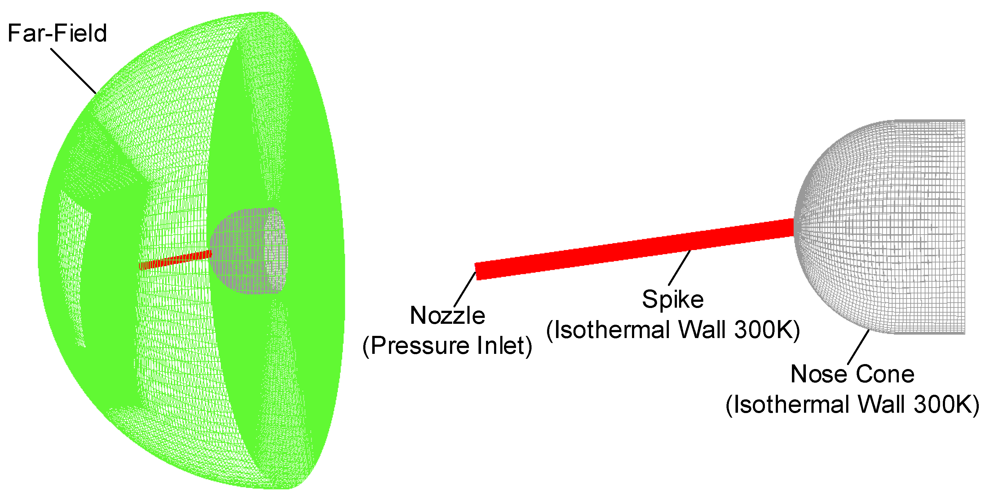
The spike and nose cone are co-axial in previous combined models based on the spike and jet. The spike and jet are the key parts for thermal protection, and the nose cone is the protected part. The adjustable non-ablative TPS is shown in Figure 1. The spike can be rotated in the direction of the free stream, so there is an angle η between the axis of the spike and the axis of the nose cone. Therefore, the angle η is the installation angle of the spike, and it is adjustable according to the angle of attack α. Table 1 shows the sizes of the adjustable non-ablative TPS, L1 is the length of the spike, L2 is the length of the nose cone, D1 is diameter of the spike and D2 is diameter of the nose cone. Figure 2 shows the numerical computational grid with the first-layer grid height of 1 × 10⁻⁶ m. The boundary conditions of the numerical model include the far field, pressure inlet (jet) and isothermal wall (nose cone and spike). Table 2 shows the jet and far-field conditions. The governing equations of the flow field are Navier–Stokes equations, which are shown as follows:
t V W d V + V ( F c F v ) n d S = 0
where W is the conservative vector, Fc is the convective flux vector, Fv is the viscous flux vector, n is the outer normal unit vector of the boundary surface dS. This paper adopts the computational fluid dynamics (CFD) method based on the Reynolds-averaged Navier–Stokes equations to analyze the aeroheating, and the AUSM+ scheme with second-order accuracy [25] and Menter’s SST k-ω turbulent model [26] are chosen. The Sutherland formula is adopted to calculate the dynamic viscosity and thermal conductivity of gas. The aeroheating analysis is conducted on a nose cone with the opposing jet in Ref. [18]. The flow field and Stanton number match the experimental results well, which demonstrates the validity of the numerical methods and turbulent model adopted in this paper.
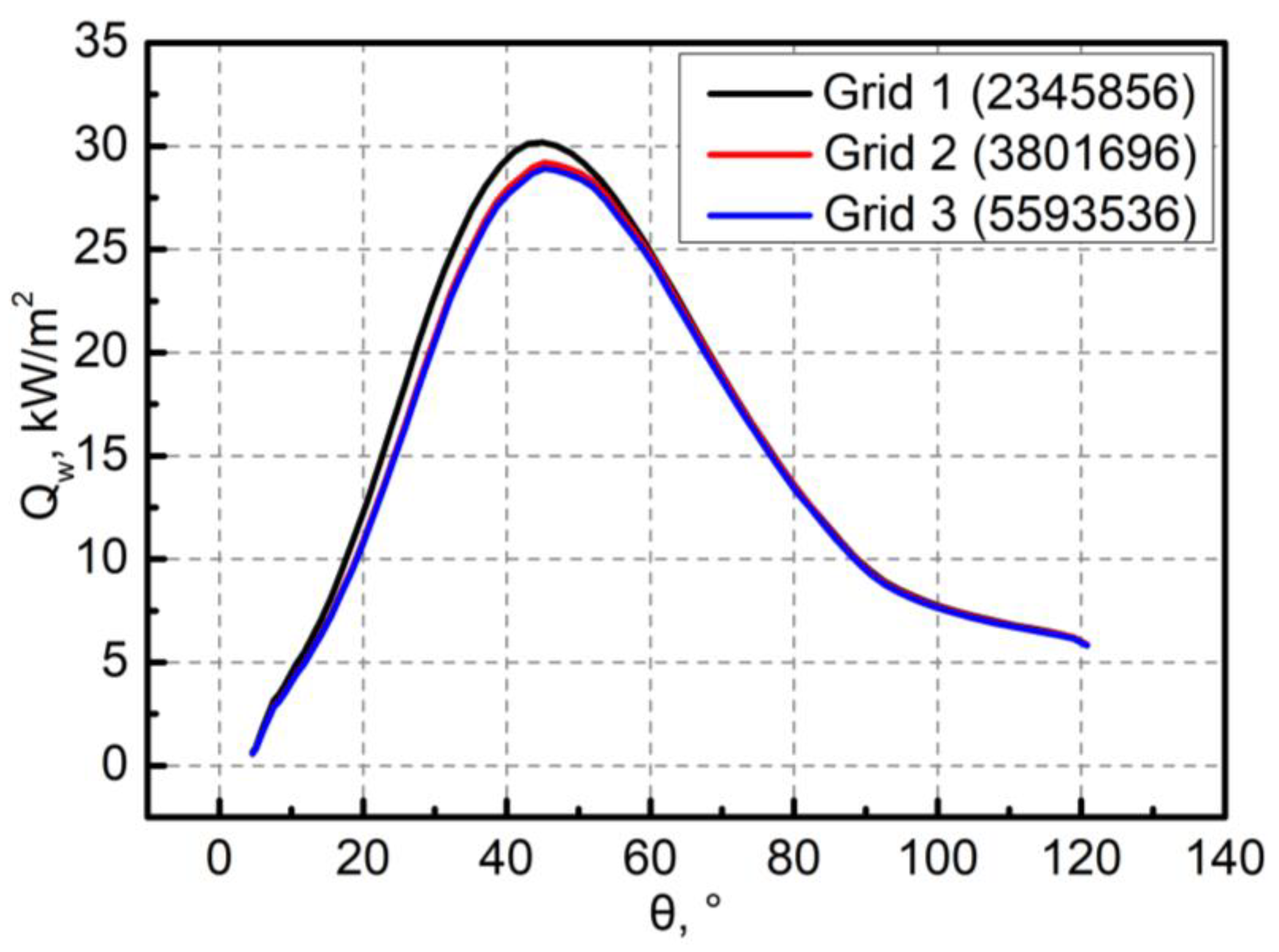
In order to conduct the grid independence analysis, different computational grids are generated with grid numbers of 2345856, 3801696 and 5593536, respectively. The aeroheating analysis is carried out and Figure 3 shows the Mach number distribution. The Mach number distributions under different computational grids have little difference. The heat flux distribution of nose cone under different computational grids is shown in Figure 4, the corresponding total heat flux Qt and peak heat flux Qmax are shown in Table 3. The relative errors of Qt and Qmax between grids 2 and 3 are only 0.49% and 0.99%, respectively. According to the above grid independence analysis, grid 2 is adopted for the subsequent studies in this paper to balance the computation accuracy and calculation effort.

3. Results and Discussion

3.1. Thermal Protection Efficiency at Non-Zero Angle of Attack

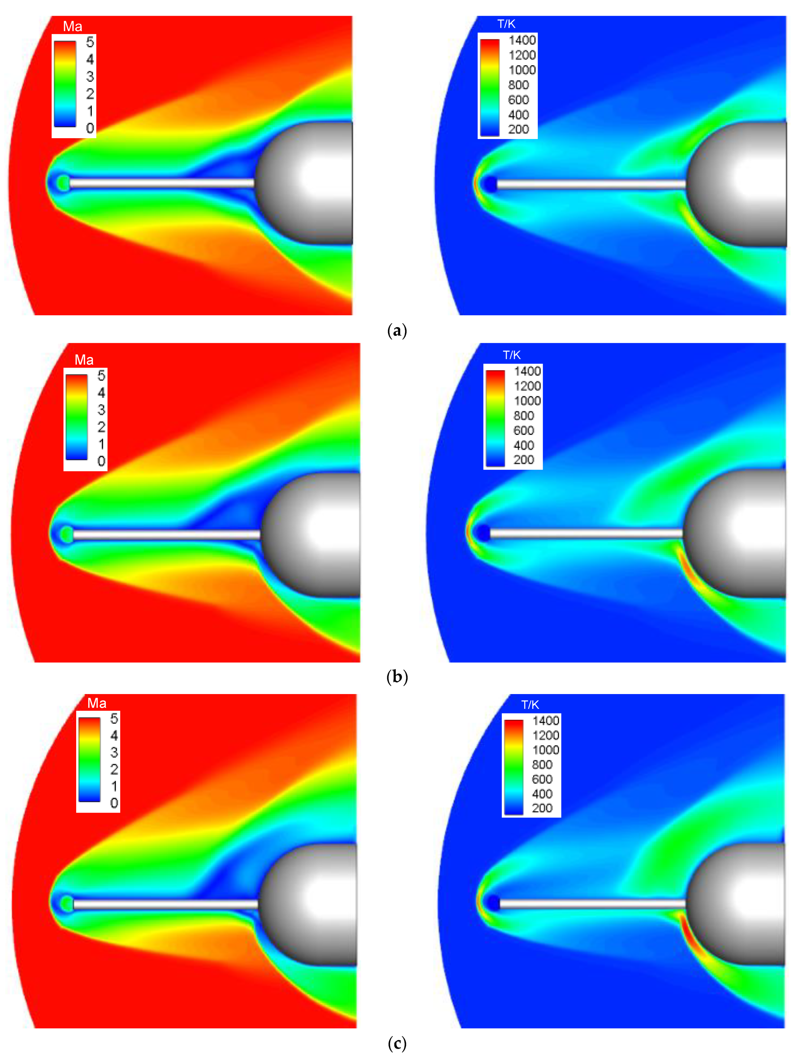
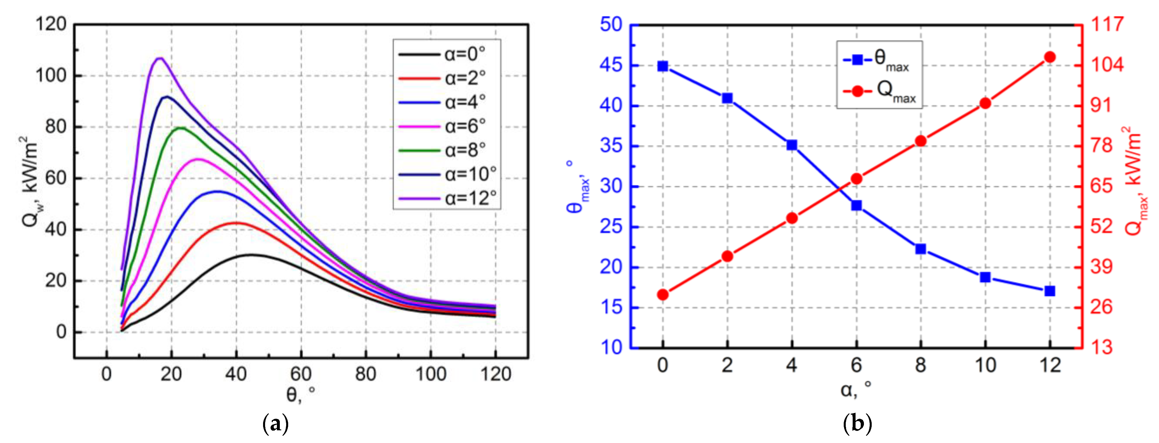
The thermal protection efficiency of the active TPS with co-axial spike and nose cone is analyzed at a non-zero angle of attack. Figure 5 shows the Mach number and temperature distributions of the flow field at different angles of attack. The windward side of the nose cone has much stronger reattachment shock at a non-zero angle of attack. Therefore, the windward side has severer aeroheating than the leeward side, and the peak heat flux must be on the windward side. In addition, increasing the angle of attack decreases the reattachment shock intensity of the leeward side, while it increases that of the windward side. Figure 6 shows the heat flux distribution, the peak heat flux Qmax and the corresponding location θmax of the windward side. The angle θ represents the position on the nose cone, the datum line is the axis of the nose cone, as shown in Figure 1. As the angle of attack increases from 0° to 12°, the peak heat flux increases from 30.18 kW/m2 to 106.71 kW/m2, up by 253.58%. The position of peak heat flux gradually moves forward and, as the angle of attack increases from 0° to 12°, θmax is reduced by 62.01%.
According to the above analysis results, the angle of attack has great influence on the peak heat flux of the nose cone. The large angle of attack will inevitably increase the aeroheating of the windward side sharply. Therefore, reducing the peak heat flux of the windward side is a key technology in the design of the active TPS.

3.2. Thermal Protection Efficiency of Adjustable Non-Ablative TPS

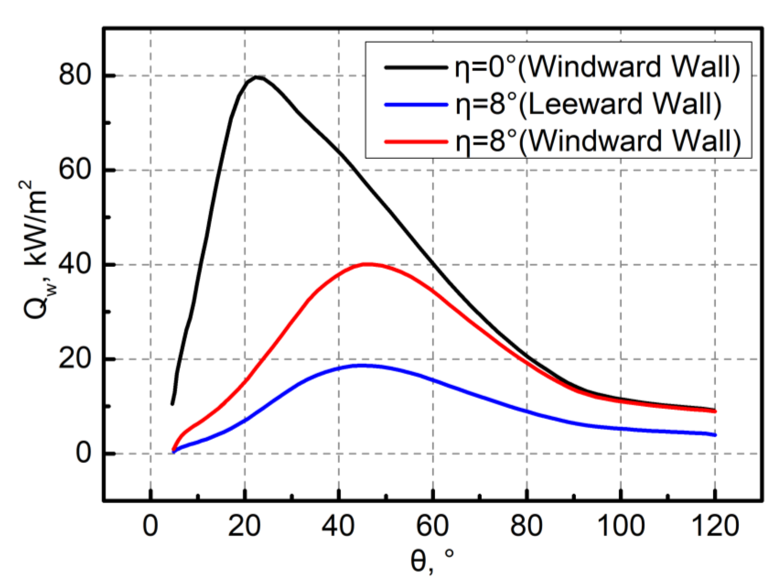
This paper analyzes the aeroheating of the adjustable non-ablative TPS at the angle of attack of 8°. The Mach number and temperature distributions of the flow field are shown in Figure 7. When the installation angle is 0°, the windward side of the nose cone has much stronger reattachment shock, and the corresponding gas temperature in the shock layer is also higher, resulting in a significant reduction of thermal protection efficiency. When the installation angle is 8°, the reattachment shock intensity and the gas temperature in the shock layer of the windward side are greatly reduced. Although the aeroheating of the leeward side increases at the installation angle of 8°, the global aeroheating of the nose cone decreases, improving the global thermal protection efficiency of the active TPS. The corresponding heat flux distribution at different installation angles is shown in Figure 8. The peak heat flux at the installation angle of 0° and 8° is 79.68 kW/m2 and 40.04 kW/m2, respectively, the peak heat flux can be reduced by 49.75% by adjusting the installation angle from 0° to 8° and it moves backward at large installation angles. Therefore, the appropriate installation angle can greatly improve global thermal protection efficiency at a non-zero angle of attack.

3.3. Optimal Installation Angle

This section attempts to find the optimal installation angle to achieve the highest thermal protection efficiency at the angle of attack of 8°. The aeroheating of the nose cone is analyzed at the installation angles of 5°, 8° and 11°, and the Mach number and temperature distributions of the flow field are shown in Figure 9. The gas temperature in the shock layer indicates that increasing the angle η weakens the aeroheating of the windward side, while it increases the aeroheating of the leeward side. At the installation angles of 5° and 8°, the windward side has much stronger reattachment shock, and the shock layer of the windward side also has a higher temperature. However, the results are reversed at the installation angle of 11°. Therefore, the optimal installation angle ηopt is between 8° and 11°. The peak heat fluxes on the windward and leeward sides should be the same, so as to achieve the highest global thermal protection efficiency of the active TPS.
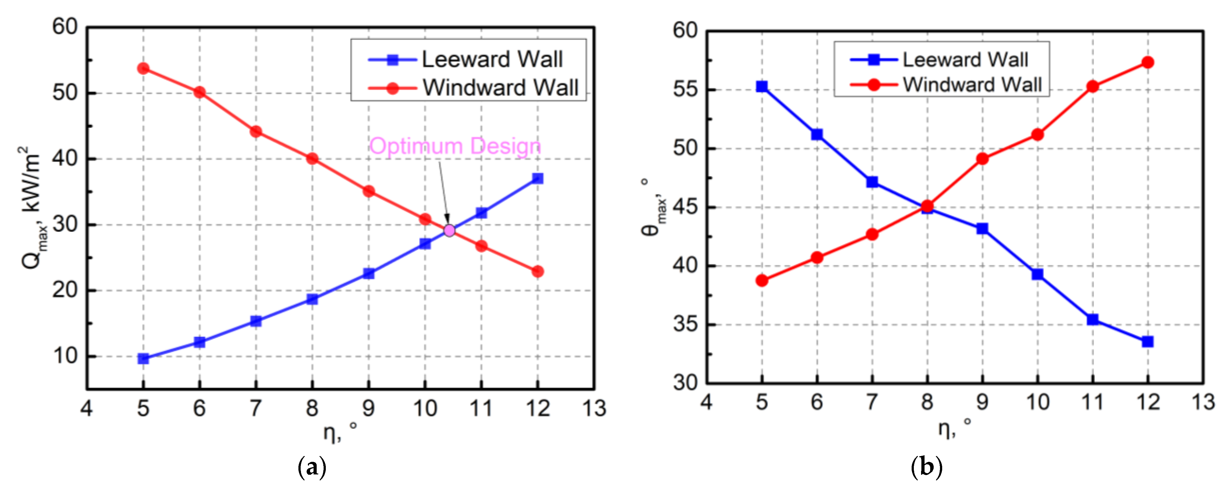
The heat flux distribution of the nose cone at different installation angles is shown in Figure 10, the peak heat flux and corresponding position are shown in Figure 11. With the angle η increasing from 5° to 12°, the peak heat flux of the windward side decreases from 53.75 kW/m2 to 22.88 kW/m2, a decrease of 57.43%. Meanwhile, the peak heat flux of the leeward side increases from 9.65 kW/m2 to 37.03 kW/m2, an increase of 283.73%. According to Figure 11a, the optimal installation angle and corresponding peak heat flux are 10.42° and 28.95 kW/m2, respectively. In addition, increasing the angle η causes the peak heat fluxes of leeward and windward sides to move forward and backward, respectively. As the angle η increases from 5° to 12°, θmax of the windward side is increased by 47.95%, while θmax of the leeward side is reduced by 39.32%.
At the angles of attack of 7°, 8° and 9°, the optimal installation angle ηopt is obtained, as shown in Table 4. The angle ηopt-α is about 2.4°. Therefore, the angle η can be automatically adjusted based on the angle of attack to achieve the highest thermal protection efficiency.

4. Conclusions

The angle of attack has great influence on the peak heat flux of hypersonic vehicles, and the dangerous point is on the windward side of the vehicles at the non-zero angle of attack. With the increase in angle of attack, the heat flux of the windward side of the vehicles rises rapidly, leading to the decrease in the global thermal protection efficiency. The peak heat flux can be reduced by 49.75% by adjusting the installation angle from 0° to 8°, and the position moves backward at large installation angles. Therefore, the appropriate installation angle can greatly improve global thermal protection efficiency at a non-zero angle of attack, thus validating the advantages of the adjustable non-ablative TPS in this paper. The optimal installation angle can be obtained by a numerical method, and the difference between the angle of attack and the optimal installation angle is about 2.4° for the proposed model. Therefore, the installation angle can be automatically adjusted based on the angle of attack to achieve the highest thermal protection efficiency.

Author Contributions

Methodology, J.H.; calculation, B.C.; writing—original draft preparation, B.C.; writing—review and editing, W.-X.Y. All authors have read and agreed to the published version of the manuscript.

Funding

This research was supported by the National Natural Science Foundation of China (52002181), Priority Academic Program Development of Jiangsu Higher Education Institutions and “the Fundamental Research Funds for the Central Universities, NO. NJ2022008”.

Institutional Review Board Statement

Not applicable.

Informed Consent Statement

Not applicable.

Data Availability Statement

Not applicable.

Acknowledgments

This research was supported by the Nanjing University of Aeronautics and Astronautics.

Conflicts of Interest

The authors declare no conflict of interest.

References

  1. Shoev, G.; Oblapenko, G.; Kunova, O.; Mekhonoshina, M.; Kustova, E. Validation of Vibration-Dissociation Coupling Models in Hypersonic Non-Equilibrium Separated Flows. Acta Astronaut. 2018, 144, 147–159. [Google Scholar] [CrossRef]
  2. Oscar, A.M.; Anurag, S.; Bhavani, V.S.; Raphael, T.H.; Max, L.B. Thermal Force and Moment Determination of an Integrated Thermal Protection System. AIAA J. 2010, 48, 119–128. [Google Scholar]
  3. Huang, J.; Yao, W.; Li, P. Uncertainty Dynamic Theoretical Analysis on Ceramic Thermal Protection System Using Perturbation Method. Acta Astronaut. 2018, 148, 41–47. [Google Scholar] [CrossRef]
  4. Qin, Q.; Xu, J.; Guo, S. Fluid-Thermal Analysis of Aerodynamic Heating over Spiked Blunt Body Configurations. Acta Astronaut. 2017, 132, 230–242. [Google Scholar] [CrossRef]
  5. Wang, S.; Zhang, W.; Cai, F.; Wang, Q.; Yan, C. Uncertainty and Sensitivity Study on Blunt Body’s Drag and Heat Reduction with Combination of Spike and Opposing Jet. Acta Astronaut. 2020, 167, 52–62. [Google Scholar] [CrossRef]
  6. Huang, W.; Li, L.Q.; Yan, L.; Zhang, T.T. Drag and Heat Flux Reduction Mechanism of Blunted Cone with Aerodisks. Acta Astronaut. 2017, 138, 168–175. [Google Scholar] [CrossRef]
  7. Vali, S.E.; Abbasi, S. Hypersonic Drag and Heat Reduction Mechanism of a New Hybrid Method of Spike, Multi-Row Discs and Opposing Jets Aerodynamic Configuration. Int. J. Heat Mass Transf. 2022, 194, 123034. [Google Scholar] [CrossRef]
  8. Mair, W.A. LXVIII. Experiments on Separation of Boundary Layers on Probes in Front of Blunt-Nosed Bodies in a Supersonic Air Stream. Lond. Edinb. Dublin Philos. Mag. J. Sci. 1952, 43, 695–716. [Google Scholar] [CrossRef]
  9. Huang, W.; Chen, Z.; Yan, L.; Yan, B.B.; Du, Z.B. Drag and Heat Flux Reduction Mechanism Induced by the Spike and Its Combinations in Supersonic Flows: A review. Prog. Aerosp. Sci. 2019, 105, 31–39. [Google Scholar] [CrossRef]
  10. Sun, X.; Huang, W.; Ou, M.; Zhang, R.R.; Li, S.B. A Survey on Numerical Simulations of Drag and Heat Reduction Mechanism in Supersonic/Hypersonic Flows. Chin. J. Aeronaut. 2019, 32, 771–784. [Google Scholar] [CrossRef]
  11. Wang, Z.G.; Sun, X.; Huang, W.; Li, S.B.; Yan, L. Experimental Investigation on Drag and Heat Flux Reduction in Supersonic/Hypersonic Flows: A Survey. Acta Astronaut. 2016, 129, 95–110. [Google Scholar] [CrossRef]
  12. Ji, C.; Liu, B.; Huang, W.; Li, S.; Meng, Z.; Yan, L.; Choubey, G. Design Exploration on the Drag Reduction and Thermal Protection over a Blunted Waverider with Multiple Opposing Jets. Aerosp. Sci. Technol. 2022, 124, 107519. [Google Scholar] [CrossRef]
  13. Wang, Z.; Zhang, X. Parametric Research on Drag Reduction and Thermal Protection of Blunt-Body with Opposing Jets of Forward Convergent Nozzle in Supersonic Flows. Acta Astronaut. 2022, 190, 218–230. [Google Scholar] [CrossRef]
  14. Hayashi, K.; Aso, S.; Tani, Y. Experimental Study on Thermal Protection System by Opposing Jet in Supersonic Flow. J. Spacecr. Rockets 2006, 43, 233–235. [Google Scholar] [CrossRef]
  15. Huang, W.; Jiang, Y.P.; Yan, L.; Liu, J. Heat Flux Reduction Mechanism Induced by a Combined Opposing Jet and Cavity Concept in Supersonic Flows. Acta Astronaut. 2016, 121, 164–171. [Google Scholar] [CrossRef]
  16. Ji, C.; Liu, B.; Huang, W.; Li, S.; Yan, L. Investigation on the Drag Reduction and Thermal Protection Properties of the Porous Opposing Jet in the Supersonic Flow: A Parametric Study with Constant Mass Flow Rate. Aerosp. Sci. Technol. 2021, 118, 107064. [Google Scholar] [CrossRef]
  17. Huang, W.; Zhang, R.R.; Yan, L.; Ou, M.; Moradi, R. Numerical Experiment on the Flow Field Properties of a Blunted Body with a Counterflowing Jet in Supersonic Flows. Acta Astronaut. 2018, 147, 231–240. [Google Scholar] [CrossRef]
  18. Huang, J.; Yao, W.; Jiang, Z. Penetration Mode Effect on Thermal Protection System by Opposing Jet. Acta Astronaut. 2019, 160, 206–215. [Google Scholar] [CrossRef]
  19. Shen, B.; Liu, W. Thermal Protection Performance of a Low Pressure Short Penetration Mode in Opposing Jet and Its Application. Int. J. Heat Mass Transf. 2020, 163, 120466. [Google Scholar] [CrossRef]
  20. Qu, F.; Sun, D.; Bai, J.; Zuo, G.; Yan, C. Numerical Investigation of Blunt Body’S Heating Load Reduction with Combination of Spike and Opposing Jet. Int. J. Heat Mass Transf. 2018, 127, 7–15. [Google Scholar] [CrossRef]
  21. Ou, M.; Yan, L.; Huang, W.; Li, S.; Li, L. Detailed Parametric Investigations on Drag and Heat Flux Reduction Induced by a Combined Spike and Opposing Jet Concept in Hypersonic Flows. Int. J. Heat Mass Transf. 2018, 126, 10–31. [Google Scholar] [CrossRef]
  22. Meng, Y.; Yan, L.; Huang, W.; Wang, Z. Fluid-Thermal Coupled Investigation on the Combinational Spike and Opposing/Lateral Jet in Hypersonic Flows. Acta Astronaut. 2021, 185, 264–282. [Google Scholar] [CrossRef]
  23. Huang, W. A Survey of Drag and Heat Reduction in Supersonic Flows by a Counterflowing Jet and Its Combinations. J. Zhejiang Univ.-Sci. A 2015, 16, 551–561. [Google Scholar] [CrossRef] [Green Version]
  24. Gerdroodbary, M.B. Numerical Analysis on Cooling Performance of Counterflowing Jet over Aerodisked Blunt Body. Shock Waves 2014, 24, 537–543. [Google Scholar] [CrossRef]
  25. Liou, M.S. A sequel to AUSM: AUSM+. J. Comput. Phys. 1996, 129, 364–382. [Google Scholar] [CrossRef]
  26. Menter, F.R. Two-Equation Eddy-Viscosity Turbulence Models for Engineering Applications. AIAA J. 1994, 32, 1598–1605. [Google Scholar] [CrossRef]
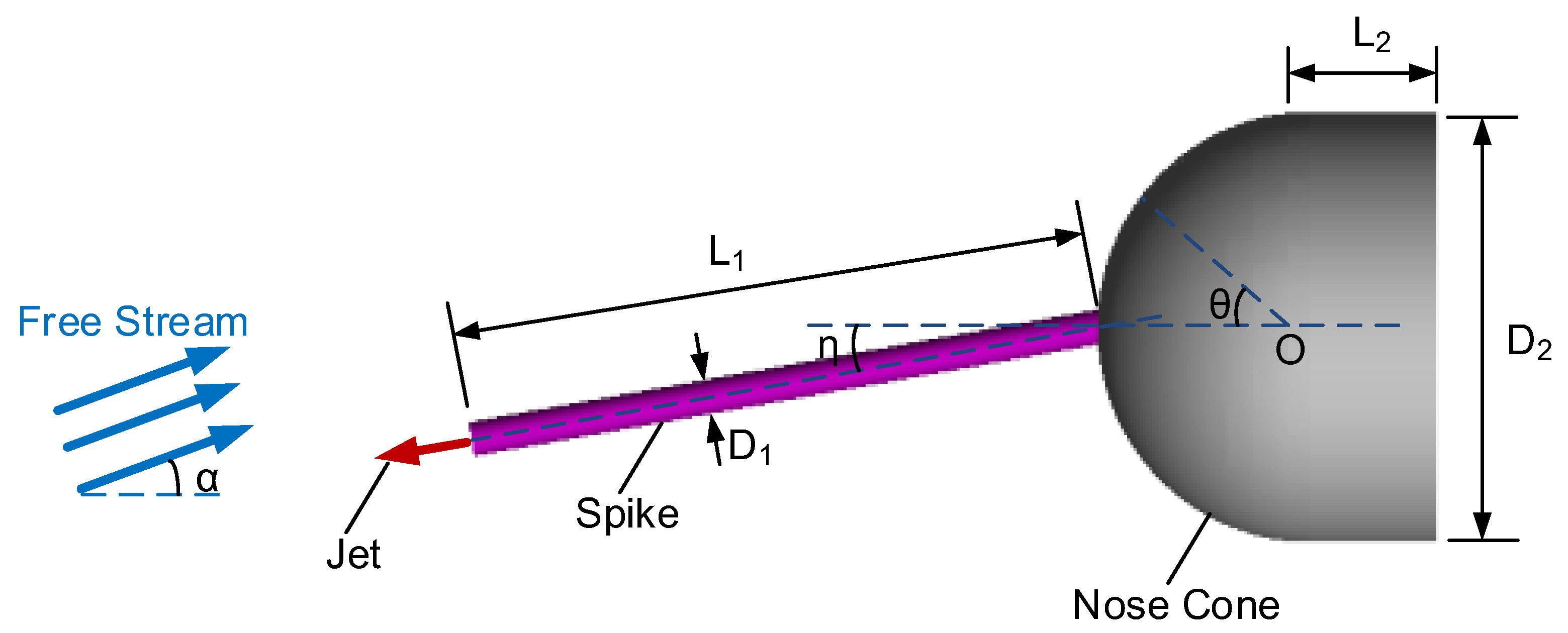
Figure 1. Physical model.
Aerospace 10 00001 g001
Figure 2. Computational grid.
Aerospace 10 00001 g002
Figure 3. Mach number distribution: (a) grid 1 (2345856); (b) grid 2 (3801696); (c) grid 3 (5593536).
Aerospace 10 00001 g003
Figure 4. Heat flux distribution of nose cone.
Aerospace 10 00001 g004
Figure 5. Numerical results of flow field: (a) α = 2°; (b) α = 6°; (c) α = 10°.
Aerospace 10 00001 g005
Figure 6. Analysis results of windward side: (a) heat flux; (b) peak heat flux.
Aerospace 10 00001 g006
Figure 7. Comparison of Mach number and temperature distributions: (a) α = 8°, η = 0°; (b) α = 8°, η = 8°.
Aerospace 10 00001 g007aAerospace 10 00001 g007b
Figure 8. Comparison of heat flux distribution of nose cone.
Aerospace 10 00001 g008
Figure 9. Flow field at different installation angles: (a) η = 5°; (b) η = 8°; (c) η = 11°.
Aerospace 10 00001 g009
Figure 10. Heat flux distribution of nose cone at different installation angles: (a) leeward; (b) windward.
Aerospace 10 00001 g010
Figure 11. Peak heat flux and corresponding position at different installation angles: (a) peak heat flux; (b) position of peak heat flux.
Aerospace 10 00001 g011
Table 1. Sizes of adjustable non-ablative TPS.
L1 (mm)L2 (mm)D1 (mm)D2 (mm)
7515450
Table 2. Jet and far-field conditions.
CharacteristicJetFar-Field
Mach number1.55
Static pressure (Pa)21.96
Static temperature (K)247.02
Total pressure (Pa)2323.6
Total temperature (K)300
Angle of attack (°)0
Table 3. Total heat flux and peak heat flux.
GridNumberQt (kW)Qmax (kW/m2)
1234585694.7730.18
2380169693.2429.19
3559353692.7828.90
Table 4. Influence of angle of attack on optimal installation angle.
α (°)789
ηopt (°)9.4210.4211.47
ηopt-α (°)2.442.422.47
Disclaimer/Publisher’s Note: The statements, opinions and data contained in all publications are solely those of the individual author(s) and contributor(s) and not of MDPI and/or the editor(s). MDPI and/or the editor(s) disclaim responsibility for any injury to people or property resulting from any ideas, methods, instructions or products referred to in the content.