Article

End-to-End Performance Evaluation of MEC Deployments in 5G Scenarios

1
Dipartimento di Ingegneria dell’Informazione, University of Pisa, 56021 Pisa, Italy
2
Intel Deutschland GmbH, Am Campeon 10-12, 85579 Neubiberg, Germany
*
Author to whom correspondence should be addressed.
J. Sens. Actuator Netw. 2020, 9(4), 57; https://doi.org/10.3390/jsan9040057
Submission received: 22 October 2020 / Revised: 24 November 2020 / Accepted: 8 December 2020 / Published: 11 December 2020

Abstract

:
Multi-access edge computing (MEC) promises to deliver localized computing power and storage. Coupled with low-latency 5G radio access, this enables the creation of high added-value services for mobile users, such as in-vehicle infotainment or remote driving. The performance of these services as well as their scalability will however depend on how MEC will be deployed in 5G systems. This paper evaluates different MEC deployment options, coherent with the respective 5G migration phases, using an accurate and comprehensive end-to-end (E2E) system simulation model (exploiting Simu5G for radio access and Intel CoFluent for core network and MEC), taking into account user-related metrics, such as response time or MEC latency. Our results show that 4G radio access is going to be a bottleneck, preventing MEC services from scaling up. On the other hand, the introduction of 5G will allow a considerable higher penetration of MEC services.

1. Introduction

Edge computing has recently emerged as a promising evolution of cloud computing. Its benefits include better scalability, especially when large amounts of data are involved (e.g., acquired from sensors), as well as lower latencies, which enable time-critical services, e.g., remote sensing and actuation or distributed gaming, and the preservation of privacy and context information (including that related to user location and access interface). Many standardization efforts and industry groups gravitate around edge computing [1]. In particular, Multi-access Edge Computing (MEC) is the leading international standard introduced by ETSI ISG (Industry Standard Group) MEC to define an architecture and services for edge computing [2,3], with particular (though not exclusive) regard to cellular network access. This standard includes both an MEC framework and architecture [4] and a set of MEC APIs specified following general RESTful API design principles [5]. According to the definition [2], “multi-access edge computing offers application developers and content providers cloud-computing capabilities and an IT service environment at the edge of the network”. This environment is characterized by ultra-low latency and high bandwidth as well as real-time access to radio network information that can be leveraged by applications. MEC provides a new ecosystem and value chain. This includes mobile operators, application developers, over the top players, independent software vendors, telecom equipment & IT platform vendors, system integrators, and technology providers, all of whom are interested in delivering MEC-based services.
While MEC is access-agnostic, it is foreseeable that users will conveniently access MEC through cellular networks, i.e., the existing 4G LTE-advanced [6] and mostly the new 5G network [1,7]. Moreover, 5G introduces several innovations, ranging from access to core network side. In particular, 5G New Radio (NR) brings considerable improvements with respect to 4G: access latency is reduced, thanks to several modifications, e.g., duration of timeslots reduced from 1 ms to 62.5 μs, guaranteeing 16× faster scheduling, and the available bandwidth is increased accordingly. This aspect (coupled with the network virtualization) makes MEC adoption particularly well suited to support next-generation services requiring very low latencies and/or high bandwidth, such as vehicular ones (from in-vehicle infotainment to assisted/cooperative driving). In addition, operators can exploit their hosting facilities at the edge of mobile networks and can open their radio access network (RAN) edge to authorized third parties, allowing them to flexibly and rapidly deploy innovative applications and services towards mobile subscribers, enterprises, and vertical segments. More specifically, when implementing MEC in mobile networks, MEC hosts are placed at the edge of the network (e.g., close to the radio access network of a 4G or 5G cellular network) and support MEC applications, leveraging edge services exposed through APIs, e.g., radio network information (RNI) API or location API, helping to tailor their computation based on the network conditions or user location. Other APIs can be exposed to MEC applications following the general design principles of RESTful APIs, to ensure interoperability and portability of MEC applications across different domains. For all these reasons, the focus of this paper is on MEC deployment in mobile networks, also due to the huge business and technology impact of 5G systems on future communications.
The deployment of the MEC infrastructure should meet different, contrasting needs. On one hand, the infrastructure owner should ensure that its hosts are used efficiently: to this aim, it would be preferable to pool resources relatively far from the users, so that temporal and spatial service usage variability can be met by leveraging statistical multiplexing, aggregating fewer computing resources. On the other hand, low-latency services should, by definition, be hosted as close as possible to the user clients, which pulls towards a capillary distribution of computing resources. Other factors, such as technology constraints (e.g., maximum size of MEC hosts), logistic constraints (e.g., accessibility of sites), or cost aspects (i.e., CAPEX and OPEX), will also play a role. The optimal trade-off point will depend on all these tradeoffs and also on the type of services considered. Finally, the actual MEC penetration will also be influenced by the dominant type of user access technology in a specific area.
Accordingly, since 5G access is expected to dominate in the near future, there is a pressing need for a sound evaluation of MEC services and deployments in 5G networks. Such an evaluation should factor in user-related performance metrics, related to both the computation and communication segments of a MEC service. For instance, the round-trip time experienced by a user for a request-response service will include both the communication latency, i.e., both access, core, and backhaul traversing up to a (possibly far away) MEC host, and to the computation time spent by the MEC app on the host itself, which in turn will depend on contention of shared computing resources (e.g., CPU, memory, storage). From this perspective, it is quite clear that deploying MEC hosts at different locations will affect both the communication latency and the contention on resources (since it will alter the number of users sharing those resources). For all these reasons, performance assessment is key for the evaluation of MEC deployment options. In particular, a proper end-to-end (E2E) evaluation should include reliable models of both the network and the computing environment. This is not easy to achieve in practice, due to the presence of many components, from access to edge and core network, and the need to cover not only PHY and MAC layers, but also traffic models in system-level simulations, and a proper workload modeling of the specific MEC app, related to the use-case under evaluation.
Some existing works (e.g., refs. [8,9]) rely on numerical evaluations of the system performance, using analytical models. Few simulation tools allow one to simulate applications and services communicating through a 5G network, notably ns3-based 5G Lena [10] and OMNeT++-based Simu5G, both of which quite recent. To the best of our knowledge, ns3 does not include models of MEC hosts. Simu5G, on the other hand, does include a MEC host model [11], but the resource contention at the latter is not modeled satisfactorily. On the other hand, there are cloud/edge computing simulators, e.g., refs. [12,13], which model the computation part but not the communication one. Intel CoFluent [14] is one such tool. However, a unified framework, including both communication and computation, is missing.
In this paper, we evaluate the performance of MEC services, specifically in-vehicle infotainment, used by users accessing them through a 5G network in mobility. We focus on the impact of the various 5G deployment alternatives on the performance of the considered MEC service and their interplay with the capacity provided within the MEC infrastructure. We claim that an effective performance evaluation of MEC services cannot be achieved by analyzing the RAN part through network-only simulation alone. Instead, we advocate that a co-simulation approach, including models of both network and compute element, would be beneficial for the analysis. However, no simulator that we know of models both satisfactorily. For this purpose, we realize a co-simulation framework where the communication part is simulated through Simu5G, and the MEC host is simulated using CoFluent. The two tools communicate via file exchange, for maximum flexibility. The above framework is used to assess various deployment options for MEC hosts. Our results show that, as one would expect, 4G is going to be a major bottleneck, preventing MEC potential to be unleashed. On the other hand, introducing 5G will enable MEC services to scale up to a considerably larger penetration, challenging the capacity of the MEC infrastructure, and requesting it to scale accordingly. One contribution of this paper also lies in the modularity of our framework: other MEC services can be evaluated by minimally modifying a setup-namely, the application model in both Simu5G (for what concerns its communication pattern) and CoFluent (for its computation pattern).
The rest of the paper is organized as follows. Section 2 describes MEC in the context of 4G and 5G networks, whereas Section 3 describes our co-simulation framework. Section 4 reports evaluation results, and Section 5 concludes the paper.

2. Multi-Access Edge Computing in 4G/5G

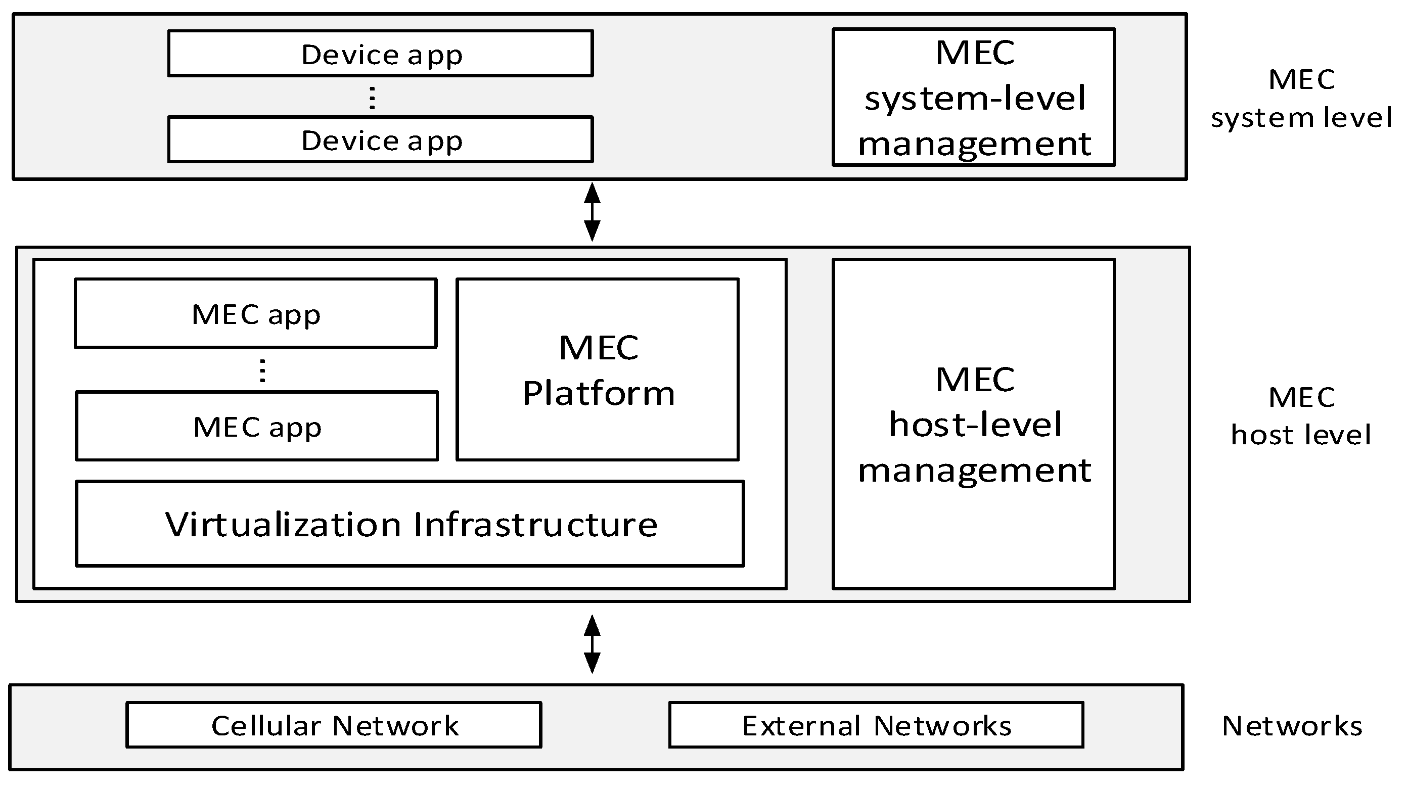
2.1. Background on Multi-Access Edge Computing

In Figure 1 the MEC architecture, as standardized by ETSI [4], is reported. The MEC architecture allows MEC apps to be executed in a virtualized environment, thus enabling dynamic and on-demand allocation of computational resources in response to users request for a particular task or service. Network operators supervising and managing an instance of a MEC system will be able to optimize resource utilization even dynamically, e.g., by migrating and/or relocating user applications between MEC hosts, following computation and communication requirements.
At the top of the hierarchy sits the MEC System Level, which maintains a global vision of the state of all the MEC Hosts within the system. The MEC System Level handles several management tasks, including handling MEC Application Instantiation requests coming from user applications, checking application requirements (e.g., MEC-services availability, maximum allowed communication latency, requested computational resources), selecting and configuring the MEC host that will host and execute the MEC application instance. In a MEC host, a MEC platform provides multiple MEC services, as defined in ref. [15]. The latter can be used by MEC apps (acting as clients for the MEC platform), to realize complex context-dependent behaviors. Example of MEC services are: the smart relocation service, which allows MEC apps to migrate among MEC hosts (e.g., to follow the least-latency path when users are mobile); the radio network information service (RNIS), which provides information on the state of the underlying network (e.g., how many users are connected, what is the load at the base station, etc.); the bandwidth manager, which sets data traffic priorities within the MEC host; the location service, that can be queried to get access to the users’ position. MEC apps run on the MEC host as virtual machines, and they can communicate both with other entities in the MEC host (e.g., the MEC platform, to use its services) and with the outside world (e.g., users’ local applications). This is achieved by the virtualization infrastructure.

2.2. MEC Deployment in Cellular Networks

The progressive introduction in the market of MEC technology and its use cases are subject to many (technical and business) decision factors [16]. In particular, from a mobile network operator (MNO) perspective, coupling MEC with their plans for progressive introduction of 5G system is a consolidated assumption, especially for those who have a migration path to an NFV-based network (in fact MEC is basically based on virtualized infrastructure, and possibly deployed also in NFV environments [17]). For this reason, it is of the utmost importance to consider MEC deployment options jointly with MNOs orientations, and coherently with their plans regarding 5G deployment phases.
A recent survey from GSMA [18] asked operators planning to launch 5G in the next two years which of the 5G Architecture Options (defined in ref. [19]) they were considering for their deployment plans. The survey revealed that it is widely expected that mobile operators will initially deploy 5G using Option 3 (named as 5G NSA, non-standalone) allowing the reuse of existing evolved packet Core (EPC) functionality (Rel. 15 early drop), and would require from infra-vendors that the subsequently planned introduction of Option 2 (5G SA, standalone) be not delayed too much (possibly with some intermediate steps, which can be found in the study). Overall, the main phases of the gradual 5G introduction (after the legacy LTE network, i.e., Option 1) are considered in the sequence of Figure 2, i.e., starting from Option 3 (5G NSA) and then moving toward Option 2 (5G SA). This paper considers this sequence as a reference for performance comparison when evaluating MEC deployments in 5G systems.
Another aspect to be taken into account in the evaluations is of course the use case. In fact, KPIs (key performance indicators) and thus the related end-to-end (E2E) performance depend on the specific use case considered. In this paper we analyze the infotainment use case for automotive scenarios (also referred to as in-vehicle entertainment), where MEC can support immersive high-definition entertainment for all vehicle occupants, including video streaming, gaming, virtual reality, office work, online education, advertisement, etc. There are several motivations for this choice, from an industrial perspective. First, automotive is a key sector for both MEC and 5G. These technologies will open the door to multiple use cases and services that can be monetized by 5G Automotive Association stakeholders. Second, in addition to traditional use-cases on connected/automated cars, infotainment is also a promising market. According to recent forecasts [20], “Intel predicts a new $7 trillion passenger economy will emerge when passengers be-come riders”; moreover, the study showed that “drivers spend 300 h a year behind the wheel and 5G offers entertainment opportunities to optimize that time as we transition from drivers to riders”. Third, infotainment interests not only automotive stakeholders, but also operators and other content providers, who may be willing to conveniently offer their “legacy” multimedia services for a comfortable in-vehicle user experience. This could be easy to offer, from a shorter time-to-market perspective. From a modeling point of view, infotainment services (as described above) can be represented by many different traffic streams. In this paper, we concentrate the evaluation on a CDN-based video-streaming traffic model.

3. Co-Simulation Based E2E Evaluation Framework

We now describe the architecture of the co-simulation framework for end-to-end simulation of MEC-enabled cellular networks. The latter is achieved by joining the Simu5G network simulator and the Intel CoFluent MEC host simulator. We first describe both simulators and then the framework that joins them.

3.1. Simu5G

Simu5G [21,22,23,24] is a system-level simulator for the data plane of the 5G NR technology, based on OMNeT++ [25]. It evolves from the well-known SimuLTE, which is a library for the simulation of 4G networks [26,27]. By integrating the INET framework [28], Simu5G allows the evaluation of end-to-end applications, incorporating the whole TCP/IP protocol stack and standard network devices, e.g., routers. It is backward-compatible with SimuLTE, and thus it allows one to simulate also 4G and mixed 4G/5G scenarios. The main components of Simu5G are the User Equipment (UE) and the gNodeB (gNB). Both elements include a Network Interface Card (NIC) module that implements all the layers of the NR protocol stack, as shown in Figure 3. The gNB can connect either directly to the Core Network (CN), i.e., in a 5G SA deployment (Option 2), or act as a secondary node (SN) and connected to a master node (MN) implemented by an LTE eNB through the X2 interface. The latter represents the 5G NSA deployment (Option 3) and enables E-UTRA/NR dual connectivity (ENDC) [29]. In an ENDC deployment, the UE can attach to either the gNB or the eNB, or both. Within Simu5G, this is modeled by endowing the UE with two protocol stacks, one for LTE and one for NR, sharing the packet data convergence protocol (PDCP) layer.
Simu5G supports carrier aggregation, where each component carrier can be configured to use either frequency- or time-division duplexing (FDD, TDD) and different numerologies, thus allowing maximum flexibility in building simulation scenarios. Simu5G models the effects of path loss, fading and inter-cell interference on message transmission, without modeling the transmission of individual symbols, which is instead the focus of link simulators such as ref. [30]. This makes it more scalable, hence apt to evaluate both network- and applications-related aspects in large-scale systems.
Simu5G can also run as a network emulator. In this last setting, it can be connected to real applications and carry packets between them in real time, with the delay and bandwidth constraint of a 5G cellular network. This is useful for rapid prototyping of MEC applications. For instance, Simu5G can be connected to the Intel OpenNESS framework for MEC hosting [31]. Work [22] evaluates Simu5G emulation capabilities.

3.2. CoFluent

Intel® CoFluent™ studio [14] is a modeling and simulation tool for optimizing, analyzing, and predicting the performance of complex systems. CoFluent allows one to model and simulate the interactions among both hardware and software elements, thus speeding up the deployment of complex systems. It simulates computing and communication cost with high accuracy and high efficiency, thus it can be effectively used to measure and evaluate the latency and throughput of data flows coming to and leaving from the MEC system. Within this work, CoFluent models a MEC environment, including the User Plane Functions (UPFs) and the MEC app within a MEC host. A high-level view of the latter is shown in Figure 4, and is composed of two main elements: the UPF and the MEC app. Data arrive at and leave the MEC host through the UPF element, which is further divided into two sub-elements, respectively one for the uplink (UL) and one for the downlink (DL) directions. The processing time T x required by a packet of size S ,   traversing the UPF in direction x is T x = S / B x , where B x is the data bandwidth of the UPF in the x direction. Packets processed by the UPF are forwarded to a MEC app, which implements the service required by the user and produces a set of data packets as a response. These packets are forwarded back to the UPF, which processes them and sends them back to the RAN. The communication path between the UPF and the MEC app is modeled through two packet queues, one per direction, which have a configurable latency of traversal. The behavior and structure of the MEC app can be customized to model the required service. In Section 4 we will describe the model of a MEC-based infotainment application.

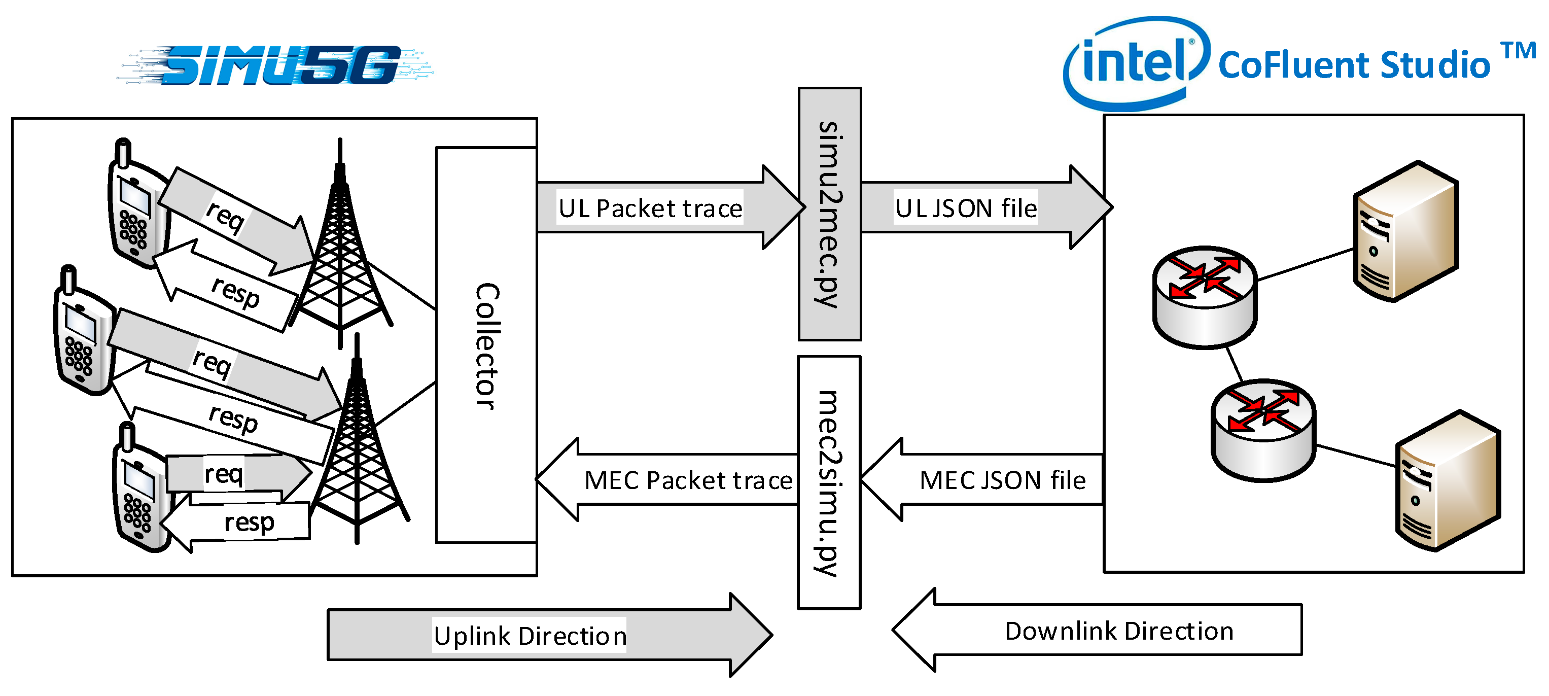
3.3. Co-Simulation Framework

Our co-simulation architecture enhances the one in ref. [31], based on a 4G network, and incorporates a 5G one. With reference to Figure 5, Simu5G and CoFluent are configured independently, each with its own models, configuration files and simulation workflows, and also run independently. Coordination is achieved via file exchange. Simu5G will simulate the 5G RAN, composed of a configurable number of UEs and BSs. Each UE runs an application client, modeling the behavior of the selected use case, and initiates service requests to the MEC infrastructure. Requests’ data packets traverse the UL of the RAN and the CN and get to the MEC host. The latter generates responses and sends them back to the UE through the DL path. BSs can be either eNBs of gNBs depending on the considered deployment. The structure of the CN depends on the deployment as well. CoFluent instead simulates the CN and the MEC environment. Service requests coming from Simu5G are processed by the MEC host, through the UPF and the MEC app, and CoFluent generates service responses, which are then fed back to Simu5G. Note that Simu5G includes also a model of the EPC, which is not instantiated to avoid duplication.
The two tools interact via file exchange as follows:
Step 1:
We instantiate a scenario, complete with UE location and mobility, and we run it in Simu5G. In the latter, UEs will generate application-level messages, to be transmitted on the UL leg of the radio access network, destined to the collector. These messages will accumulate delay on their way up, due to user contention, protocol delays, channel quality impairments, etc. The traffic that arrives to the collector (i.e., that exits the RAN) leaves Simu5G as well. We timestamp the traffic, and we log both timestamp and message sizes to Logfile#1 file. More specifically, we log both the simulated time at which a message is generated at the UE, and the simulated time at which it reaches the collector. These times are expressed in Simu5G’s units.
Step 2:
We run CoFluent, using Logfile#1 as an input. The MEC elements modeled in CoFluent process the requests generated by the UEs, and the MEC server generates replies accordingly. These replies will contain a payload, which depends on the traffic model used within CoFluent. These replies are sent back to the RAN. Similar to step 1, replies are timestamped and logged in the Logfile#2 file. In the latter, timestamps are expressed in CoFluent’s units. During step 2, time is spent traversing the necessary MEC elements, e.g., queueing up at contention points.
Step 3:
We run Simu5G once more, using the same scenario as for step 1. More specifically, the UE location and mobility are the same. We now use Logfile#2 to generate the replies to be transmitted to the UEs using the DL leg of the RAN. As in step 1, replies accumulate delay due to interference, channel issues, congestion and protocol mechanisms.
We note that file reads and writes are actually made in C++ within the co-simulation endpoints. This is done, however, only at the beginning (read) and at the end (write) of the simulation. This allows us to avoid unnecessary file-based operations during the execution of the simulations, thus adding a negligible overhead to the simulation performance. Another benefit of this approach is that it allows us to compute end-to-end delays (e.g., the round-trip time of a request—RTT) without having to synchronize simulated times in the two frameworks. In fact, the RTT can be computed as the sum of the delays incurred in steps 1, 2, and 3, each one of which is computed within a simulator. Thus, if messages keep track of the delay accumulated thus far, the RTT is obtained automatically at the end of step 3. Finally, using a file-based interaction allows us to obtain a co-simulation framework with minimal modification of the two involved simulators, and notably without any impact on their core functionalities. This last characteristic is particularly important in the perspective of upgradability.
The above co-simulation framework is realized by minimally modifying Simu5G and CoFluent, coding some software tools to interface the two. In the UL direction the following elements have been implemented:
  • An application that issues service requests periodically at a UE, written in C++.
  • A C++ collector application that collects all the UE messages (after they have got to the respective BSs) and prints Logfile#1.
  • A program written in python, simu2mec.py, that converts Logfile#1 to a structured JSON file, to be used as an input to CoFluent.
Dually, some more apps have been coded to cope with the DL return trip:
  • A program written in python, mec2simu.py, that parses the MEC packet trace produced by CoFluent, and generates a structured JSON file, which specifies for each packet, its ID, the ID of the UE that generated it, and the timestamp.
  • A C++ application that takes the above JSON file as an input and generates a trace of DL messages accordingly. These messages are those that will be injected at step 3, to reach the interested UEs via their serving BSs.
  • A C++ application, running on UEs, that collects responses and generates reports (e.g., by computing the RTT of each request and assembling it with some aggregator, say the mean value).

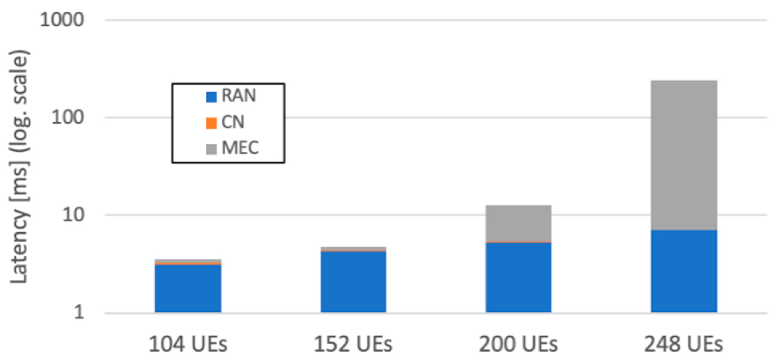
4. Performance Evaluation

In this section, we assess the performance of a MEC-enabled service in various system deployments. Our aim is to highlight the impact and contribution of the different system components (i.e., RAN, CN, MEC host) on the E2E service performance.
The application scenario we consider is an infotainment service, provided in a Cellular Vehicle-to-Everything (C-V2X) environment, whose logical view is shown in Figure 6. Each vehicle carries a user client that runs within a UE and connects to a MEC host through the cellular network. The client periodically issues a request for an infotainment service. The server is realized as a MEC app residing in a MEC host and responds to requests by sending the client a transcoded version of a prerecorded video stream. On each request, the client specifies one of the video formats reported in Table 1, a higher video quality corresponding to a higher bandwidth. The MEC app is composed of two parts: a request handler and a streamer. The former receives and processes the service requests, identifying the video and its format, and notifies the streamer. The latter transcodes and transmits the video stream, one frame each 40 ms. Video frames are finally received at the client, which collects them and computes metrics. In our co-simulation framework, the client is implemented as a UDP application running on a UE on Simu5G, whereas the infotainment server is implemented as an MEC app within CoFluent.
We define frame latency as the time between the transmission of a video frame from the MEC app and its reception at the UE. This measures the “age” of the information received by the user, and can be further divided into a MEC latency, i.e., from the generation of a video frame at the MEC app to its packets leaving the MEC server, a CN latency, i.e., the time it takes these packets to reach the gNB/eNB, and a RAN latency, i.e., the time between the arrival of a video frame at the gNB/eNB and its reception at the UE. We consider a RAN composed of 57 cells, deployed according to the hexagonal tessellation shown in the left part of Figure 7 (we show only the first two tiers of cells for readability). Each site hosts three co-located BSs and each BS radiates towards the center of the respective hexagon. The inter-site distance is 500 m. UEs are deployed according to an urban-grid vehicular scenario, shown in the right part of Figure 7, which corresponds to the area defined by the dashed rectangle to the left. BSs outside that area are simulated as external cells.
In order to assess the impact of different 4G/5G and MEC deployments, we consider three scenarios, coherently with the phases previously described in Section 2.2:
  • Baseline LTE deployment (Figure 8, top): the BSs are LTE eNBs and the MEC app is co-located with the S-GW and the P-GW in a centralized EPC site. We assume a one-way latency between the RAN and the MEC of 15 ms [17].
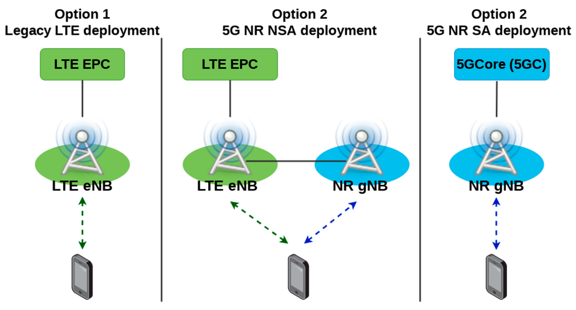
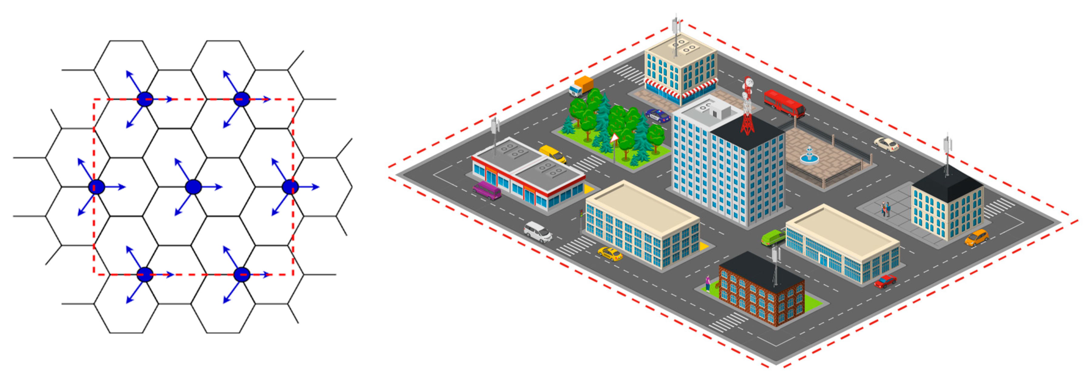
  • 5G NSA deployment (Figure 8, center): the BSs are again LTE eNBs and each of the three central cells also has a gNB placed in the center of the hexagons, connected to the corresponding eNB via X2 and radiating power according to an omnidirectional pattern. The LTE eNBs are connected to a distributed EPC site in proximity of the RAN. Both S-GW and P-GW, as well as the MEC, are considered as virtual network functions (VNFs). Since the path between the RAN and the MEC involves two VNFs, we assume a one-way latency of 200 µs [32]. For the X2 interface, we assume 5 ms latency [33,34].
  • 5G SA deployment (Figure 8, bottom): the BSs are gNBs connected to a distributed 5G Core (5GC). Again, the MEC is a VNF connected to (at least) a UPF, acting as PDU session anchor in the 5GC, and terminating to the data network. Since there is only one VNF between the RAN and the MEC, the considered one-way latency is 100 µs.
The main simulation parameters are summarized in Table 2. We first run simulations with a varying number of UEs (24 to 40), increasing the video bitrate. Figure 9 shows the percentage of DL frame occupied in the 4G RAN, for the 4G and 5G NSA scenarios. The figure shows that this increases with the video bitrate, however keeping below 50%. In the 5G NSA case, the 4G DL is occupied even less, due to the gNB offloading. The difference in user experience is clarified in Figure 10, describing the frame latency and its breakdown. It is quite evident that, in the 4G scenario, both the RAN and the CN introduce a considerable delay. On the other hand, even high video bitrates are well tolerated in the 5G NSA scenario, and the 5G SA one exhibits negligible delays. In all the three scenarios, the MEC delay is negligible. Figure 11 shows the standard deviation of the frame latency, which measures the jitter, and is a meaningful indicator of user-perceived Quality of Experience. It is quite evident that, although the DL is far from being congested, in the 4G scenarios jitters comparable to twice the inter-packet time and more can occur, meaning that packets will need considerable buffering at the UE. This does not happen with either 5G NSA or 5G SA. These results show that the 4G network is going to represent the bottleneck for MEC services such as this, and that only deploying 5G will alleviate that. In order to find the point at which the MEC host starts acting as a bottleneck, we ran simulations with a considerably higher number of users (up to 248) in a 5G SA deployment. This time we used a low bitrate video, to avoid saturating the RAN. The results are shown in Figure 12, and they clearly show that the MEC host becomes congested around 200 users. However, before this occurs, the bulk of the latency is still due to the 5G RAN.

5. Conclusions and Future Work

This paper presented a methodology to evaluate MEC deployments with 4G/5G access and the results of its application. The methodology consists in using detailed system-level simulators (namely, Simu5G and CoFluent) to simulate the communication and computation parts of an E2E service with MEC, and joining them into a flexible co-simulation framework. We have used the above tool to compare MEC deployment options, namely 4G, 5G non-standalone, and 5G Standalone, as for their suitability to support an infotainment service with MEC. Our results show that 4G radio access is going to be the bottleneck from a QoE perspective, allowing only a small number of users, and virtually leaving most of the MEC computation power untapped. With 4G, large jitters will impair the service even in a relatively uncongested RAN. Deploying 5G, already in NSA but especially in the SA option, is going to make a large difference. With 5G, the same service will be able to accommodate considerably more users before MEC hosts become a bottleneck.
Due to the inherent flexibility of the above framework, this work can be extended in several directions. For instance, in-car task offloading from car to MEC, e.g., critical workloads to be offloaded to MEC in the case of sudden blade failure in the car.

Author Contributions

Conceptualization, A.V., G.N., and G.S.; software, A.V. and G.N.; validation, A.V. and G.N.; writing—original draft preparation, A.V., G.S., and D.S.; writing—review and editing, A.V., G.N., G.S., and D.S. All authors have read and agreed to the published version of the manuscript.

Funding

Work partially supported by the Italian Ministry of Education and Research (MIUR) in the framework of the Cross-Lab project (Departments of Excellence). The subject matter of this paper includes description of results of a joint research project carried out by Intel Corporation and the University of Pisa. Intel Corporation reserves all proprietary rights in any process, procedure, algorithm, article of manufacture, or other results of said project herein described.

Conflicts of Interest

Dario Sabella is affiliated with Intel, which funded some of the activities that are described in this paper. Dario Sabella took part in the writing, contributing in particular to the background description and to the scenario definition. The funder did not influence the claims or the results that are presented in this paper.

References

  1. Intel White Paper. Edge Computing: From Standard to Actual Infrastructure Deployment and Software Development. Available online: https://intel.ly/2Wx7Gy4 (accessed on 10 November 2020).
  2. ETSI MEC (Multi-Access Edge Computing). Available online: https://www.etsi.org/technologies/multi-access-edge-computing (accessed on 10 November 2020).
  3. Sabella, D.; Vaillant, A.; Kuure, P.; Rauschenbach, U.; Giust, F. Mobile-Edge Computing Architecture: The role of MEC in the Internet of Things. IEEE Consum. Electron. Mag. 2016, 5, 84–91. [Google Scholar] [CrossRef]
  4. ETSI GS MEC 003 V2.1.1 (2019-01). Multi-access Edge Computing (MEC); Framework and Reference Architecture. January 2019. Available online: https://bit.ly/2yOmYps (accessed on 10 November 2020).
  5. ETSI GS MEC 009 V2.1.1 (2019-01). Multi-Access Edge Computing (MEC); General Principles for MEC Service APIs. Available online: https://bit.ly/2zzYCj6 (accessed on 10 November 2020).
  6. ETSI White Paper No. 24. MEC Deployments in 4G and Evolution Towards 5G, First Edition—February 2018. Available online: https://bit.ly/2T5AKe7 (accessed on 10 November 2020).
  7. ETSI White Paper No. 28. MEC in 5G Networks. June 2018. Available online: https://bit.ly/3bzCLFI (accessed on 10 November 2020).
  8. Emara, M.; Filippou, M.C.; Sabella, D. MEC-Assisted End-to-End Latency Evaluations for C-V2X Communications. In Proceedings of the 2018 European Conference on Networks and Communications (EuCNC), Ljubljana, Slovenia, 18–21 June 2018; pp. 1–9. [Google Scholar]
  9. Pencheva, E.; Atanasov, I.; Velkova, D.; Trifonov, V. Evaluation of Multi-access Edge Computing Deployment Scenarios. In Proceedings of the 2019 9th Annual Information Technology, Electromechanical Engineering and Microelectronics Conference (IEMECON), Jaipur, India, 13–15 March 2019; pp. 155–160. [Google Scholar]
  10. Patriciello, N.; Lagen, S.; Bojovic, B.; Giupponi, L. An E2E simulator for 5G NR networks. Simul. Model. Pract. Theory 2019, 96, 101933. [Google Scholar] [CrossRef] [Green Version]
  11. Nardini, G.; Virdis, A.; Stea, G.; Buono, A. SimuLTE-MEC: Extending SimuLTE for Multi-Access Edge Computing. EPiC Ser. Comput. 2018, 56, 35–42. [Google Scholar] [CrossRef]
  12. Castañé, G.G.; Nuñez, A.; Carretero, J. iCanCloud: A Brief Architecture Overview. In Proceedings of the 2012 IEEE 10th International Symposium on Parallel and Distributed Processing with Applications, Leganes, Spain, 10–13 July 2012; pp. 853–854. [Google Scholar]
  13. Kliazovich, D.; Bouvry, P.; Khan, S.U. GreenCloud: A Packet-Level Simulator of Energy-Aware Cloud Computing Data Centers. J. Supercomput. 2010, 62, 1–5. [Google Scholar]
  14. Available online: https://www.intel.com/content/www/us/en/cofluent/overview.html (accessed on 10 November 2020).
  15. ETSI GS MEC 002. Mobile Edge Computing (MEC); Technical Requirements; 2016-03. Available online: https://www.etsi.org/deliver/etsi_gs/MEC/001_099/002/01.01.01_60/gs_MEC002v010101p.pdf (accessed on 10 November 2020).
  16. Sabella, D.; Reznik, A.; Frazao, R. Multi-Access Edge Computing in Action; Informa UK Limited: London, UK, 2019. [Google Scholar]
  17. Sabella, D.; Nikaein, N.; Huang, A.; Xhembulla, J.; Malnati, G.; Scarpina, S. A Hierarchical MEC Architecture: Experimenting the RAVEN Use-Case. In Proceedings of the 2018 IEEE 87th Vehicular Technology Conference (VTC Spring), Porto, Portugal, 3–6 June 2018; pp. 1–5. [Google Scholar] [CrossRef]
  18. GSMA. Operator Requirements for 5G Core Connectivity Options. May 2019. Available online: https://bit.ly/2WOgiiM (accessed on 10 November 2020).
  19. 3GPP RP-161266. Architecture Configuration Options for NR. Available online: https://portal.3gpp.org/ngppapp/CreateTDoc.aspx?mode=view&contributionUid=RP-161266 (accessed on 10 November 2020).
  20. Intel 5G Connected Vehicles Webinar, Referring to the Study from Strategy Analytics. Accelerating the Future: The Economic Impact of the Emerging Passenger Economy. June 2017. Available online: https://intel.ly/2Wwqpdt (accessed on 10 November 2020).
  21. Nardini, G.; Stea, G.; Virdis, A.; Sabella, D. Simu5G: A System-level Simulator for 5G Networks. In Proceedings of the 10th International Conference on Simulation and Modeling Methodologies, Technologies and Applications, Paris, France, 8–10 July 2020. [Google Scholar]
  22. Nardini, G.; Stea, G.; Virdis, A.; Sabella, D.; Thakkar, P. Using Simu5G as a Realtime Network Emulator to Test MEC Apps in an End-To-End 5G Testbed. In Proceedings of the 2020 IEEE 31st Annual International Symposium on Personal, Indoor and Mobile Radio Communications, London, UK, 31 August 2020. [Google Scholar]
  23. Nardini, G.; Sabella, D.; Stea, G.; Thakkar, P.; Virdis, A. Simu5G–An OMNeT++ Library for End-to-End Performance Evaluation of 5G Networks. IEEE Access 2020, 8, 181176–181191. [Google Scholar] [CrossRef]
  24. Simu5g Website. Available online: http://simu5g.org (accessed on 10 November 2020).
  25. OMNeT++ Website. Available online: https://omnetpp.org (accessed on 10 November 2020).
  26. Virdis, A.; Stea, G.; Nardini, G. Simulating LTE/LTE-Advanced Networks with SimuLTE. In Advances in Intelligent Systems and Computing; Springer Science and Business Media LLC: Heidelberg, Germany, 2015; Volume 402, pp. 83–105. [Google Scholar]
  27. SimuLTE Website. Available online: http://simulte.com (accessed on 10 November 2020).
  28. INET Library Website. Available online: https://inet.omnetpp.org (accessed on 10 November 2020).
  29. 3GPP TS 37.340 v16.1.0. Evolved Universal Terrestrial Radio Access (E-UTRA) and NR; Multi-Connectivity; Stage 2 (Rel. 16). March 2020. Available online: https://portal.3gpp.org/desktopmodules/Specifications/SpecificationDetails.aspx?specificationId=3198 (accessed on 10 November 2020).
  30. Pratschner, S.; Tahir, B.; Marijanovic, L.; Mussbah, M.; Kirev, K.; Nissel, R.; Schwarz, S.; Rupp, M. Versatile mobile communications simulation: The Vienna 5G Link Level Simulator. EURASIP J. Wirel. Commun. Netw. 2018, 2018, 226. [Google Scholar] [CrossRef] [Green Version]
  31. Virdis, A.; Nardini, G.; Stea, G.; Shi, Y.; Bian, Z. A Co-Simulation Framework to Evaluate Edge Deployment Options and Performance. In Proceedings of the 2020 IEEE International Conference on Communications Workshops (ICC Workshops), Dublin, Ireland, 7–11 June 2020. [Google Scholar]
  32. Filippou, M.C.; Sabella, D.; Riccobene, V. Flexible MEC service consumption through edge host zoning in 5G networks. In Proceedings of the 2019 IEEE Wireless Communications and Networking Conference Workshop (WCNCW), Marrakech, Morocco, 15–18 April 2019. [Google Scholar]
  33. Wang, H.; Rosa, C.; Pedersen, K.I. Dual connectivity for LTE-advanced heterogeneous networks. Wirel. Netw. 2015, 22, 1315–1328. [Google Scholar] [CrossRef] [Green Version]
  34. Michalopoulos, D.S.; Maeder, A.; Kolehmainen, N. 5G Multi-Connectivity with Non-Ideal Backhaul: Distributed vs Cloud-Based Architecture. In Proceedings of the 2018 IEEE Globecom Workshops (GC Wkshps), Abu Dhabi, UAE, 9–13 December 2018; pp. 1–6. [Google Scholar] [CrossRef] [Green Version]
  35. 3GPP TR 36.873 v12.7.0. Study on 3D Channel Model for LTE. December 2017. Available online: https://portal.3gpp.org/desktopmodules/Specifications/SpecificationDetails.aspx?specificationId=2574 (accessed on 10 November 2020).
Figure 1. Overview of the Multi-access Edge Computing Framework.
Jsan 09 00057 g001
Figure 2. Main phases of 5G architecture options [7], as defined by ref. [19].
Jsan 09 00057 g002
Figure 3. Main components of Simu5G.
Jsan 09 00057 g003
Figure 4. MEC host model on CoFluentTM.
Jsan 09 00057 g004
Figure 5. Implementation of the co-simulation framework.
Jsan 09 00057 g005
Figure 6. Logical view of the infotainment application.
Jsan 09 00057 g006
Figure 7. RAN deployment (left) and urban-grid scenario (right). [credits to icograms.com].
Jsan 09 00057 g007
Figure 8. LTE deployment with centralized EPC (top), 5G NSA deployment with distributed EPC (center), 5G SA deployment with distributed 5GC (bottom).
Jsan 09 00057 g008
Figure 9. DL resource-block occupancy in the 4G and 5G-NSA scenarios.
Jsan 09 00057 g009
Figure 10. Frame-latency breakdown in a scenario with 24 UEs.
Jsan 09 00057 g010
Figure 11. Standard deviation of the inter-packet times at the UE.
Jsan 09 00057 g011
Figure 12. Frame-latency breakdown in the 5G SA scenario.
Jsan 09 00057 g012
Table 1. Video Formats.
Video FormatBitrateFrame Size (Fixed)
240p400 kbps2000 Bytes
720p2400 kbps12,000 Bytes
Table 2. Main Simulation parameters.
Video FormatBitrate
Bandwidth20 MHz (100 Resource Blocks)
Carrier Frequency2 GHz
6 GHz for gNBs in NSA
Numerology index (5G only)2 (60-kHZ subcarrier spacing)
Tx PowerBS: 46 dBm; UE: 23 dBm
Fading effectsEnabled
Path loss model[35]
UE mobilityLinear, ~ U ( 10 , 18 ) m/s
CN latency (one-way)LTE: 15 ms
5G: 200 µs (NSA), 100 µs (SA)
X2 latency5 ms
Simulation time200 s
UPF UL/DL bandwidth100 Gb/s
UPF-APP and APP-UPF delay5.4 µs
REQ processing time50 µs
Frame creation time200 µs
Frame size{2000, 12,000, 24,000} bytes
Video duration8 s
Request period12 s
Publisher’s Note: MDPI stays neutral with regard to jurisdictional claims in published maps and institutional affiliations.

