Article

A Joint Routing and Channel Assignment Scheme for Hybrid Wireless-Optical Broadband-Access Networks †

by
Amitangshu Pal
1,*,‡ and
Asis Nasipuri
2,‡
1
Computer and Information Sciences, Temple University, Philadelphia, PA 19122-1801, USA
2
Electrical and Computer Engineering, The University of North Carolina at Charlotte, Charlotte, NC 28223-0001, USA
*
Author to whom correspondence should be addressed.
This paper is an extended version of our paper published in Pal, A.; Nasipuri, A. JRCA: A joint routing and channel assignment scheme for wireless mesh networks. In Proceedings of the IEEE IPCCC 2011, Orlando, FL, USA, 17–19 November 2011.
These authors contributed equally to this work.
J. Sens. Actuator Netw. 2018, 7(4), 44; https://doi.org/10.3390/jsan7040044
Submission received: 31 August 2018 / Revised: 5 October 2018 / Accepted: 10 October 2018 / Published: 16 October 2018

Abstract

:
In this paper, we investigate mechanisms for improving the quality of communications in wireless-optical broadband access networks (WOBAN), which present a promising solution to meet the growing needs for capacity of access networks. This is achieved by using multiple gateways and multi-channel operation along with a routing protocol that effectively reduces the effect of radio interference. We present a joint route and channel assignment scheme with the objective of maximizing the end-to-end probability of success and minimizing the end-to-end delay for all active upstream traffic in the WOBAN. Performance evaluations of the proposed scheme are presented using ns-2 simulations, which show that the proposed scheme improves the network throughput up to three times and reduces the traffic delay by six times in presence of 12 channels and four network interface cards (NICs), compared to a single channel scenario.

1. Introduction

Access networks are the last mile of the communication networks that connect the telecommunication central office (CO) to the residential or business users. Conventionally, access networks are implemented by optical technologies such as passive optical networks and wireless networks such as wireless mesh networks. While optical networks enable high-bandwidth and long distance communications, wireless technologies are used for flexibility and low bandwidth uses. However, the current trend of Internet usage involves rapid growth of users [1], growing demands for bandwidth-intensive services, as well as the desire for flexibility (anytime-anywhere service). These complex set of requirements are accelerating the research on efficient and cost-effective access infrastructures where optical-wireless combinations are seen as a promising approach. The wireless-optical broadband-access network (WOBAN) is a novel hybrid access network paradigm with the combination of high-capacity optical backhaul and highly flexible wireless front-end that can provide higher bandwidth in a cost effective manner. In WOBAN architecture, optical fibers are provided as far as possible from the CO to the end users and wireless access is provided in the front end. Because of its excellent compromise, this WOBAN architecture enjoys low deployment costs because of lower fiber costs than traditional passive optical networks.
A WOBAN consists of a passive optical networks (PON) at the back end and a multi-hop wireless mesh networks at the front end. At the back end, optical line terminal (OLT) resides in the CO and feed to multiple optical network units (ONUs) through a traditional fiber network. Each ONU is connected to one or more wireless gateway(s) that provide the interface to a wireless mesh network comprising the wireless front end. Thus, if a mesh router needs to send a packet to the Internet, it has to send it to any one of the gateways, which is then forwarded through the optical part of the WOBAN. Since the bottleneck of communication performance, such as throughput and delay, is largely on the wireless mesh network component of the hybrid network, it is of interest to design mechanisms to maximize the throughput performance of anycasting between the wireless routers and any one of the available gateways in a WOBAN.
Co-channel interference is the main factor that reduces the network throughput in the wireless networks. To cope for this, the IEEE 802.11 standards provide multiple non-overlapping frequency channels to support multiple simultaneous transmissions in the same interference region. For example, IEEE 802.11b/g offers three non-overlapping 20 MHz channels, while IEEE 802.11a offers 24 non-overlapping 20 MHz channels and 12 non-overlapping 40 MHz channels. IEEE 802.11n and 802.11ac also provide multiple non-overlapping channels of different bandwidths. Table 1 summarizes major IEEE 802.11 standards and their available non-overlapping channels. By exploiting the advantages of multiple channels and multiple radios, the system performance of mesh networks can be improved significantly compared to the single-channel wireless access networks [2]. However, all of these benefits can only be achieved by applying a carefully designed channel assignment scheme so as to utilize these multiple channels and radios effectively. Moreover, since co-channel interference at a node is determined by the assignments of channels to the neighboring nodes as well as their traffic patterns, the solution to this problem involves channel assignment as well as routing. Our interest is to develop a holistic solution that addresses the channel assignment and anycast-routing problems together for maximizing the throughput performance in the wireless mesh.
The central challenges for addressing this problem include (a) determining effective measures for estimating the route quality by accurately modeling the effects of interference in addition to route length in the wireless domain of the WOBAN, (b) using the quality measures in an anycast WOBAN where the mesh routers can reach to any of the gateways for accessing the Internet, and (c) addressing the computational complexity of solving the anycast routing and channel assignment problems together. As the proposed joint solution involves significant computation complexity, a key issue is to develop an approach that utilizes tools to reduce the computational burden for practical implementations. In this regard, our main contributions in this paper are as follows:
  • First, we develop a novel route quality metric that utilizes performance characteristics of data packet transmissions, and effectively captures the effects of intraflow and interflow interference.
  • Second, we propose a joint routing and channel assignment protocol (JRCA) that tries to maximize the overall quality of communication paths in the network by employing the developed route quality metric. For channel assignment, JRCA employs a combination of backtracking and genetic algorithm to reduce the convergence time. The distinctive aspect of this work is that the WOBAN architecture enables the gateways to collaborate with each other through the optical backbone for determining the optimum gateway and route selections for all active nodes in the network. This allows for a hybrid design approach, i.e., combination of centralized and distributed, which is distinct from those followed in (purely) wireless mesh networks.
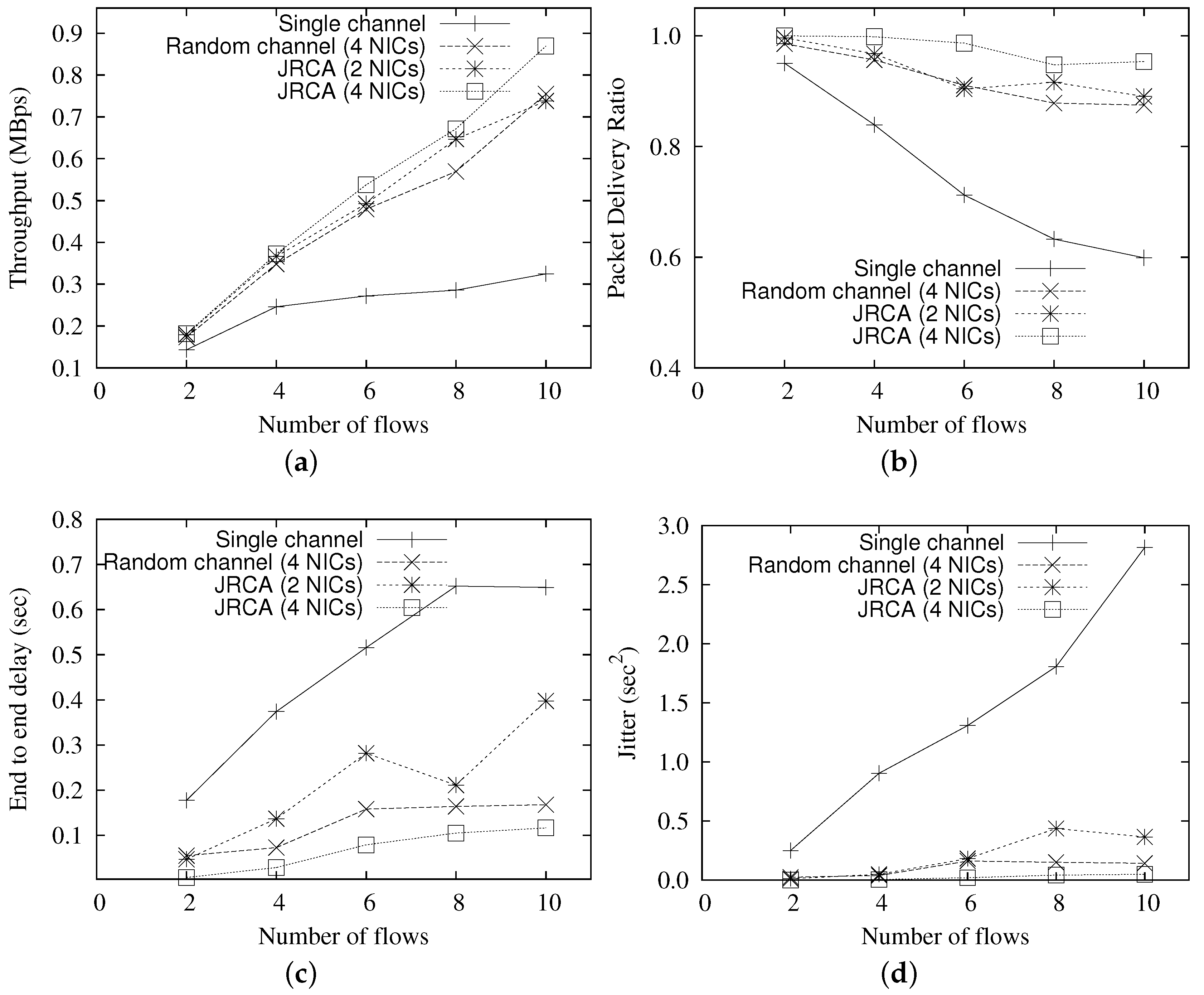
  • Finally, we evaluate the performance of JRCA using extensive simulations. Performance evaluations show that, compared to a single channel scenario, JRCA improves the network throughput by up to three times, whereas reduces the traffic delay by ∼six times, with 12 orthogonal channels and four NICs per router.
The rest of the paper is organized as follows. In Section 2, we provide a brief description of WOBAN architecture and the benefits of WOBAN compared to PON and wireless mesh networks. Next, we address the routing and channel selection problem in the wireless mesh network for a given set of ONUs and wireless mesh routers, and their locations. We also review prior work on related topics and unique challenges addressed in this work. In Section 3, we describe the approach for developing a route quality metric that takes into account wireless interference and channel contention. Next, we explore the problem of joint routing and channel assignment scheme in a multi-channel, multi-gateway WOBAN architecture, which significantly reduces the co-channel interference and channel contention. This is presented in Section 4. In Section 5, we present extensive performance evaluations of our proposed routing protocols in comparison to others. Conclusions are presented in Section 6.

2. System Overview and Research Directions in WOBAN

2.1. Current Trends in Access Networks

Current access networks can be broadly divided into two classes: those using high-bandwidth optical access networks, and those that use wireless access networks. The dominant broadband optical access technology is PON (shown in Figure 1a). A PON connects the telecom central office (CO) to businesses and residential users by using a single–wavelength channel in the downstream direction (i.e., from Optical Line Terminal (OLT) at CO to Optical Network Units (ONU)), and a channel on a different wavelength in the upstream direction (i.e., from ONUs to OLT). The key function of OLT is to control the information flow across the PON, while residing in a central office. On the other hand, ONU resides on the customer’s premises to provide last-mile connectivity. The PON interior elements are basically passive combiners, couplers and splitters. Since no active elements exist between the OLTs and the ONUs, PONs are robust networks that are cost and power efficient as well. To ensure multiple access capability, several Time-division multiple access (TDMA) PONs such as Ethernet PON (EPON), Gigabit PON (GPON), Broadband PON (BPON) are deployed by several carriers. Eying for higher bandwidth requirements and better quality of service of future access networks, Wavelength Division Multiplexing-PON (WDM-PON) architecture is proposed in the literature which employs WDM multiplexing in both upstream and downstream directions of the access network. Broadband optical networks extend broadband communication links close to the user and leaves the user with the option of using short range mobile access technologies such as WiFi.
On the other hand, the popular approach for extending the range of untethered or mobile access is to use wireless mesh networking, for instance, using WiFi and WiMAX. WiFi (using the IEEE 802.11 standard) technology is mainly used in local-area networks and offers low bit rate (max 54/11/54 Mbps for 802.11a/b/g, respectively) and limited range (typically 100 m) communications. WiMAX (standard: IEEE 802.16) is particularly suitable for wireless metropolitan-area networks (WMAN) because of its offers high bit rate and long range communications. WiMAX supports data rates up to 75 Mbps in a range of 3–5 km, and typically 20–30 Mbps over longer ranges. Wireless mesh networks (shown in Figure 1b) use wireless mesh routers to forward traffic to a gateway using multi-hop communications. The growing demands on broadband connectivity require development of novel approaches for the access network architecture. A potential solution may be achieved by integrating the advantages of the both worlds, where “wireless needs optical” for greater bandwidth availability, especially at the back-end, and the “optical needs wireless” for cost effective and flexible network deployment over large geographic areas. The WOBAN architecture proposes achieving this compromise between high-bandwidth optical access and untethered wireless access networks to extend the reach of the Internet in a cost-effective and efficient manner.

2.2. WOBAN Architecture and the Motivation behind WOBAN

As stated earlier, a WOBAN consists of a multi-hop multi-radio wireless mesh network at the front end that connects to an optical access network providing connection to the Internet at the back end. At the back end, the dominant technology is the PON having OLTs located at the CO and optical network units (ONUs) that are connected to the wireless gateways routers. In the wireless infrastructure, standard WiFi and WiMAX technologies can be used for wireless mesh networks. The subscribers, i.e., the end-users (also known as mesh clients) send packets to their neighborhood mesh routers. The mesh routers inject packets to the wireless mesh of the WOBAN. The mesh routers can reach any of the gateways/ONUs through multi-hop routing. A WOBAN provides the flexibility of optimum utilization of the optical and wireless components to achieve scalability, cost-efficiency, and performance. In the upstream direction (mesh routers to ONUs), the routing is basically anycast and in the downstream direction (ONUs to mesh routers), the routing is unicasting as traffic is sent from an ONU to a particular mesh router only. The gateways/ONUs can be strategically placed over a geographic region to better serve the wireless users. The detailed WOBAN architecture is depicted in Figure 1c. Below, we summarize the advantages of WOBAN as opposed to fully optical and wireless access:
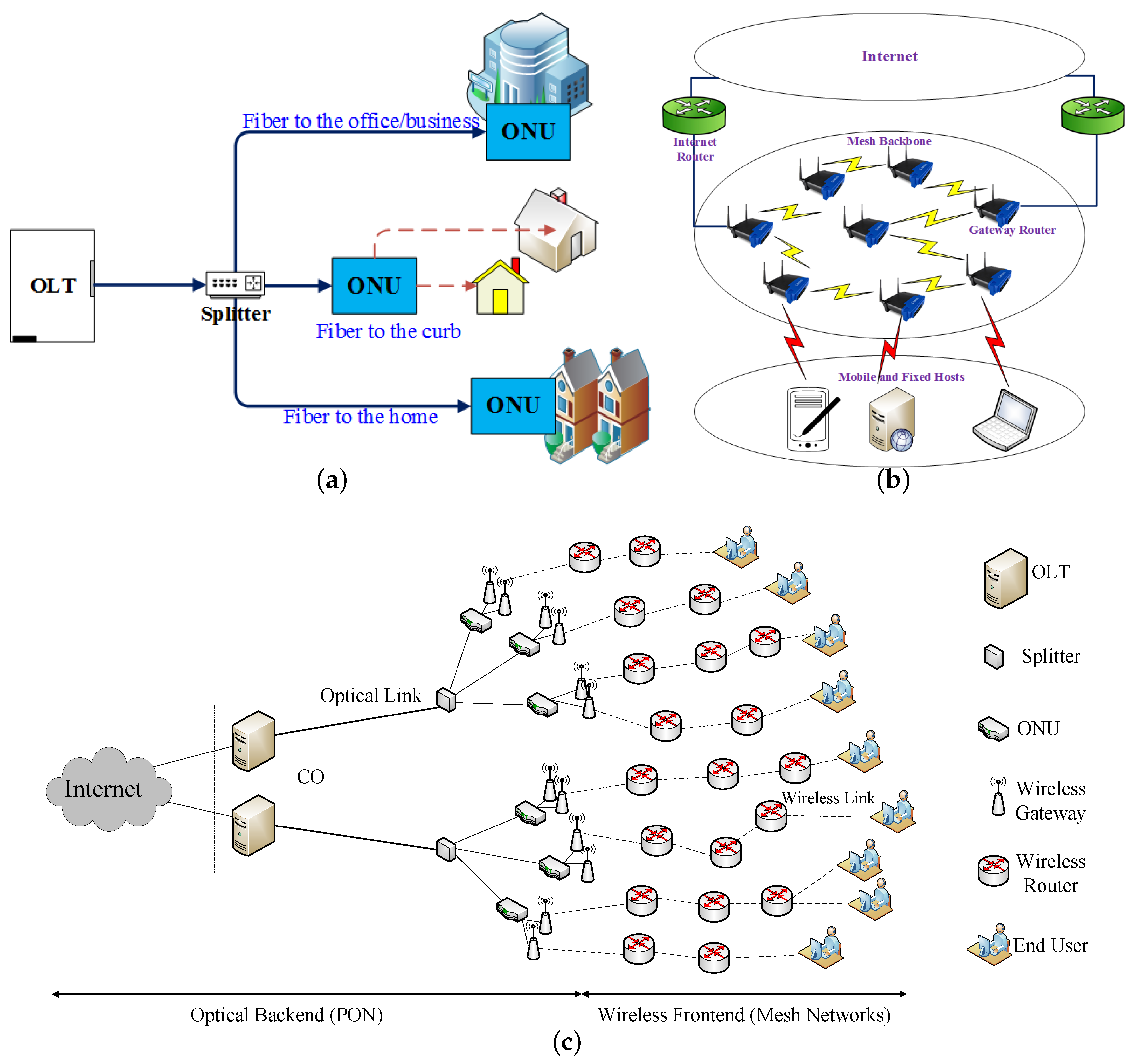
  • A WOBAN can be more cost efficient as compared to a PON, since fibers in a WOBAN do not need to be penetrated to every subscriber’s homes, premises or offices. One estimate [4] shows that the cost to wire 80% of the US households with broadband lies between $60–120 billion, whereas using wireless drastically reduces the cost to $2 billion. Even in developing regions, the cost of providing and maintaining wireline broadband connectivity is prohibitively expensive. WOBAN-like hybrid architecture is particularly appealing in these scenarios where fiber layout is only needed from central offices to some ONU points, beyond which the wireless frontend consists of mesh routers that can be flexibly deployed.
  • The wireless mesh architecture provides more flexible wireless access to users compared to optical access networks. It is often difficult to deploy optical fibers and equipments in highly populated areas as well as in rugged environments. In these environments, the wireless front-end can provide easy coverage and connectivity in a cost-effective manner. Hybrid optical-wireless networks, if properly designed, can achieve better deployment flexibility than traditional PON.
  • The self-healing nature of the wireless front end makes WOBAN more robust and fault tolerant than traditional PON. In traditional PON, a fiber cut between the splitter and an ONU or between the splitter and the OLT makes some or all of the ONUs disconnected from OLT. In WOBAN, the traffic disrupted by any failure or fiber cut can still be forwarded through the mesh routers using multi-hop routing to other ONUs and then to the OLT.
  • WOBAN enjoys the advantages of anycast routing [5,6]. If a gateway is congested, a wireless router can route its traffic through other gateways. This reduces load and congestion on that gateway and gives WOBAN a better load-balancing capability. Such schemes require information exchanges among the gateway nodes which is a key feature of a WOBAN, as they are connected through optical fibers but is absent in a pure wireless mesh network.
  • WOBAN has much higher bandwidth capacity compared to the low capacity wireless networks, which reduces the traffic congestion, packet loss rate as well as end-to-end packet delay. For example, in Figure 1b, multiple mesh routers in the mesh backbone result in traffic congestion, wireless interference, and channel contention, which can be improved using multi-channel communication. However, even in case of multi-channel communication, interference is a limiting factor, which can be alleviated by collaboratively using the optical and wireless technologies.
  • The distinctive aspect of the WOBAN architecture is that it enables the gateways to collaborate with each other through the optical backbone for determining the routing and load-balancing decisions based on the varying network traffic. This allows for a hybrid design approach, i.e., combination of centralized and distributed, which provides better flexibility and fault tolerance ability than those followed in (purely) wireless mesh networks.

2.3. Related Works

We note that some of the key design issues of WOBAN, namely, quality based routing, anycasting, and channel assignment, have been extensively researched in the domain of (purely) wireless mesh network. In the following, we review some of the notable concepts from prior work on these topics. Later, we also summarize the research that addressed different architectural and routing challenges in WOBAN.
Anycasting Based Routing and Channel Assignment: In [7], the authors propose a multi-gateway wireless mesh network routing protocol (MAMSR) based on the Dynamic source routing (DSR) protocol. The routing metric used in MAMSR is hop count, where gateway and route selection is performed on the basis of the first RREP packet received by the source. A hybrid anycast routing is proposed in [8] where the network is divided into two regions: proactive and reactive. Nodes that are very close to any gateway are in the proactive region and send packets to this gateway only. Nodes that are not in the proactive region are part of the reactive region; these nodes choose gateways that carry minimum load. Another multi-gateway association scheme is proposed in [9], where the shortest paths from any node to each gateway and the available bandwidth in all the paths are computed. The path that has the largest available bandwidth is selected in a greedy manner. In [10], the authors propose a scheme where each source keeps track of its nearest gateway as the primary and other gateways as secondary gateways. All nodes generally send traffic to their primary gateways. If the primary gateway is congested, sources with high traffic are notified by the gateway to switch their traffic to some other gateways.
The multi-channel assignment is also well-mined in wireless networks. The existing literature on channel assignment schemes can be broadly classified into three categories: static assignment, dynamic assignment and hybrid assignment. While static channel assignment strategies [11,12,13,14,15,16] permanently assign channels to the network interfaces, the dynamic strategies [17,18,19,20] switches their interfaces from one channel to the other in between successive data transmissions. On the other hand, the hybrid approaches [21,22] adopt static assignment for few fixed interfaces, whereas use dynamic assignment on some switching interfaces.
Architecture and Routing in hybrid wireless-optical networks: Hybrid wireless-optical networks have been manifested with different names such as WOBAN [4], FiWi [23], MARIN [24], GROWNet [25], ACCORDANCE [26]. Relevant surveys on wireless-optical networks are reported in [27,28].
Much literature has described the problem of optimal ONU placement based on the traffic demand in a geographic area. In [29], the authors propose a greedy algorithm where a number of predefined points are considered as initial candidates to place the ONUs. Then, each user identifies the primary ONU which is the closest and then the locations of the primary ONUs are calculated as the center of the users. An improvement of this greedy algorithm by using simulated annealing and hill climbing are described in [30]. In [31], the authors propose a mixed-integer-programming approach to solve the problem of ONU placement.
Several routing schemes are presented in the context of WOBAN. Delay and capacity aware routing is proposed in [32,33]. A minimum-hop routing and shortest-path routing is proposed in [4]. An efficient radio and channel assignment scheme in a multi-radio WOBAN is discussed in [34]. Analytical modeling of the IEEE 802.11 Distributed Coordination Function (DCF) in radio-over-fiber (RoF) wireless LANs is proposed in [35].

2.4. Challenges Addressed

The key challenge addressed in this work is to design network protocols for achieving adequate quality of service, in terms of throughput and delay, in the wireless domain of the WOBAN. The system model considers that the wireless access network is a mesh network comprising a fixed set of wireless mesh nodes or routers, which employ multihop routing to convey wireless data packets between user stations to ONUs. Since communication is assumed to be between end users and an external destination that can be reached through any ONU using the optical backbone, this involves quality aware anycast routing between each user and any ONU. As interference is a key factor that affects data transmissions in multi-hop wireless networks, our primary objective is to take routing decisions based on interference considerations in addition to the path length, which is often the primary factor considered for routing in dynamic multi-hop wireless networks. We propose an approach that tries to optimize the end-to-end probability of success (POS) and delay in all active routes in the network by using a novel quality based routing metric summarized in Section 3.
In addition, to improve the throughput performance, wireless mesh networks have been considered to use multi-channel radios, usually employing multiple network interface cards (NICs). Having multiple wireless interfaces greatly reduces wireless interference and channel contention, which results in higher network throughput. Optimizing the performance of multi-channel mesh networks involves optimum channel selection at the mesh nodes, which is coupled with the routing problem. This necessitates the need for developing a quality aware routing in multi-gateway, multi-channel WOBAN, which is described in Section 4. It is assumed that all communication requests are directed towards the gateway, which serves as the centralized manager for all routing decisions based on global knowledge of node locations and activities. Channel assignment at the radio interfaces of the wireless routers must be solved together instead of solving them in isolation. At the same time, the collaboration among multiple gateways also fits well in the WOBAN context, where the gateways are connected through optical fibers, which is absent in a pure wireless mesh network.

3. A Quality Aware Routing Metric for WOBAN

In this section, we describe a suitable routing metric for a WOBAN in terms of the end-to-end probability of success and end-to-end delay of a transmitted data packet. In [36,37] we describe the detailed analysis of POS and delay of a wireless link, which we summarize briefly. We assume that all the routers are static and their locations are known to the gateways. The wireless routers use IEEE 802.11 CSMA/CA MAC for collision avoidance. The necessary variables are enlisted in Table 2.

3.1. Transmission Delay

The transmission delay in 802.11 channels depends on a number of components, of which the queuing and access delays are significant. The queuing delay Q d is the property of the transmitting router, which is the time that a packet has to wait in its transmission queue before it actually reaches the head of the queue and starts contending for the channel. On the other hand, the access delay Q a is the time that a packet needs to wait at the head of the transmission queue before the channel contention is resolved by CSMA/CA and the packet gets access to the channel and starts transmission. The total delay T d , which is the sum of the average queuing and access delays, is an important factor affecting the quality of a communication link.
In the presence of RTS/CTS packets, the time for a packet to reach the destination depends on the active neighbors of the sender ( n a ) as well that of the receiver (which we denote by n b ). This is due to the fact that a data packet is not transmitted unless the receiver has access to the channel to send the CTS. Thus, the total delay T d ( n a , n b ) in the presence of RTS/CTS can be approximately estimated as:
T d ( n a , n b ) = A ( n a 2 + n b 2 ) + B ( n a + n b ) + C ,
where A , B , C varies with load and are obtained by best fitting the simulated values [37].

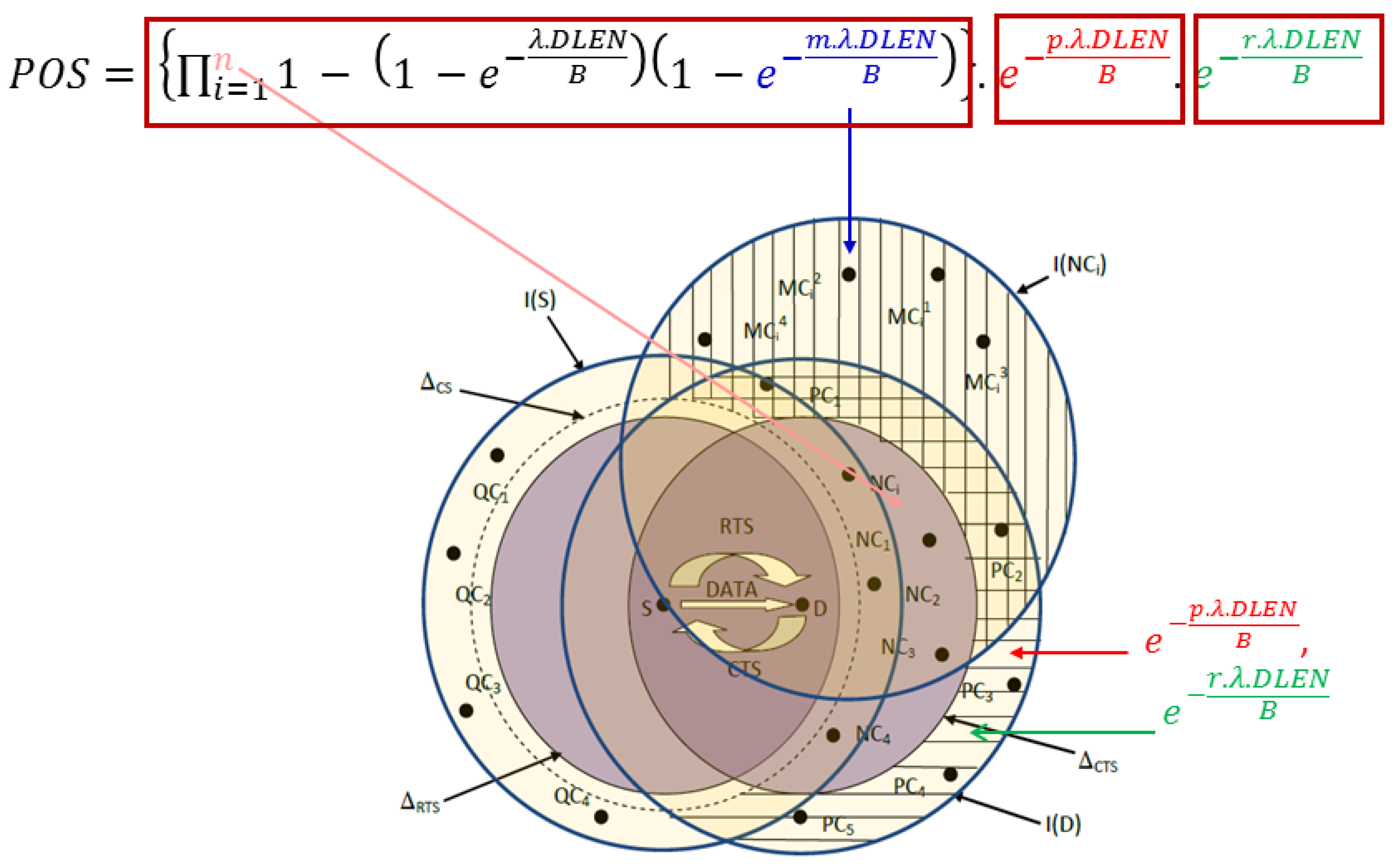
3.2. Probability of Success

We now evaluate the probability of successful reception of a transmitted packet on a test link. When the RTS/CTS option is enabled, a data packet is only transmitted when the RTS/CTS exchange is successful, i.e., the channel is found to be clear both at the transmitting and receiving nodes. However, the transmitted data packet can still be lost due to interference caused to the data packet or the ACK packet. Here, we analyze the possible events that can cause these transmission failures, which are explained with the help of Figure 2. In the figure, S D represents the test link, Δ R T S and Δ C T S denote the regions where the RTS and CTS packets for the test link can be received, and Δ C S denotes the area around S where nodes can sense the transmission from S. For any node i, I ( i ) denotes the area from where a transmission from any node j I ( i ) can interfere with a packet being received at i. We assume that the nodes generate data packets based on a Poisson process with an arrival rate if λ . The data packet length and the channel bandwidth are assumed to be D L E N bits and B bits/s, respectively. Our approach is to explore various cases where events can lead to unsuccessful data transmission. For each of these cases, we evaluate the factors that affect the POS, as outlined below:
Case-1: The transmitted data packet is unsuccessful due to interference from nodes that are within the interference range of the D but outside its transmissions range. This is due to the fact that these nodes will not receive the CTS sent by D. In Figure 2, we mark these nodes as P C i , of which we assume p nodes are sending and r nodes are receiving. As derived in [37], the probability of success of the DATA packet in the presence of these nodes are e λ × D L E N × p B and e λ × D L E N × r B , respectively.
Case-2: The test data packet can be unsuccessful due to interference from nodes that are within the transmission range of D but fail to receive the CTS packet. A node located in the Δ C T S that is outside the Δ C S of S (marked as N C i in Figure 2) may not receive the CTS from D correctly due to an overlapping transmission from M C j i (refer to Figure 2). In general, if there are m such interferers among M C i j , then the probability that the CTS is not received by N C i is 1 i = 1 m e λ × D L E N B = 1 e λ × D L E N × m B .
The probability that N C i , having failed to receive the CTS from D, interferes with the reception of the DATA packet at D is then given by ( 1 e λ × D L E N B ) , which is the probability that an RTS transmission from N C i overlaps with the test DATA packet at D. If there are n such nodes ( N C 1 , N C 2 , , N C n ), then the DATA transmission will be successful with a probability of i = 1 n 1 ( 1 e λ × D L E N B ) ( 1 e λ × D L E N × m B ) .
By taking into account all the factors described above, the probability of success of a transmitted data packet using the RTS/CTS handshake is given by
P S = i = 1 n 1 1 e λ × D L E N B 1 e λ × D L E N × m B × e λ × D L E N × q B × e λ × D L E N × r B .
It must be noted that some additional factors affect the POS and hence the accuracy of Equation (2). Firstly, Equation (2) is based on the assumption that all interferers transmit independently, which is not exactly true as there are dependencies among these interferers. Secondly, in Equation (2), we assume that the arrival rate of all the interferers is identical. Nevertheless, our model provides a good estimate of the POS for a test link considering the various measurable parameters in a static multihop wireless network, such as the number of interferers m , n , p , and r in different scenarios.

4. Quality-Aware Routing and Channel Assignment in Multi-Channel Multi-Gateway WOBAN

With this, we now address the anycasting framework by considering a multi-gateway WOBAN where the wireless access network can connect to the fiber backbone through one of several gateways. As mentioned earlier, the multi-gateway WOBANs with anycast routing have several features (such as providing redundancy, reducing congestion, better utilization of network resources, etc.) that can be utilized for improving the quality of service of wireless connections. In addition to multiple gateways, the wireless routers are also equipped with multiple radio interfaces, which are capable of operating on multiple channels. However, this leads to a joint gateway selection and routing problem, which is computationally hard. In addition, the network parameters may vary over time, which increases the complexity of the problem. For instance, as illustrated in Figure 3, a user B may be initially connected to G 6 , which provides the best quality of service among a number of available gateway nodes in the absence of any other active node in its vicinity. However, if user A becomes active after B is connected, it may be necessary to switch B to G 5 and connect A to G 6 so that the two active routes do not interfere with each other and the overall performance is optimized. Such decisions depend on a number of parameters that affect the quality, which need to be evaluated at different locations and times, making the optimization difficult.
With this framework and assumptions, we next propose the routing protocol JRCA for multi-gateway, multi-channel WOBAN. Our approach for maximizing the quality metric through joint route and channel selection requires an effective representation of co-channel interference, which we model using the conflict graph. For multi-channel WOBAN, we define the route quality metric for route R of length v as follows:
Q ( R ) = f = 1 v P S ( I f ) f = 1 v T d ( n a f , n b f ) + f = 1 v s d × y f .
Here, f is a link on the route from source to gateway, P S ( I f ) is the POS of link f, I f is the set of interferers. T d ( n a f , n b f ) is the delay with n a f and n b f active neighbors at the sender and the receiver end, respectively. s d is the switching delay for an interface to switch from one channel to another and y f is a binary variable which is 1 when the interfaces of link f switch and 0 otherwise. For positive switching delay, this model prefers routes that avoid frequent switching of channels.
For channel assignment, we use a conflict graph to model wireless interference. We first form the conflict graph (discussed in Section 4.1) and use a vertex coloring scheme (where colors represent channels) for channel assignment. From this point onwards, we use the word channel and color interchangeably. However, as the vertex coloring problem is an NP-complete problem [38], we apply the genetic algorithm [39] to solve it, which has been successfully applied to several problems to avoid a brute-force-search. We propose a novel mechanism to reduce the number of vertices on which we apply the genetic algorithm, to reduce the convergence time. This is achieved by planarizing the conflict graph using vertex deletion (in Section 4.2), applying backtracking to color the planar subgraph (in Section 4.3) and then using the genetic algorithm on the vertices that are not part of planar subgraph and those that violate the interface constraint (in Section 4.4). The details of the scheme are described in the following sections.

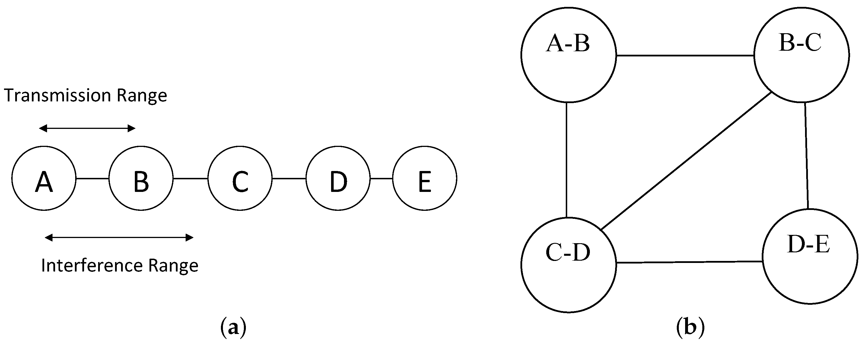
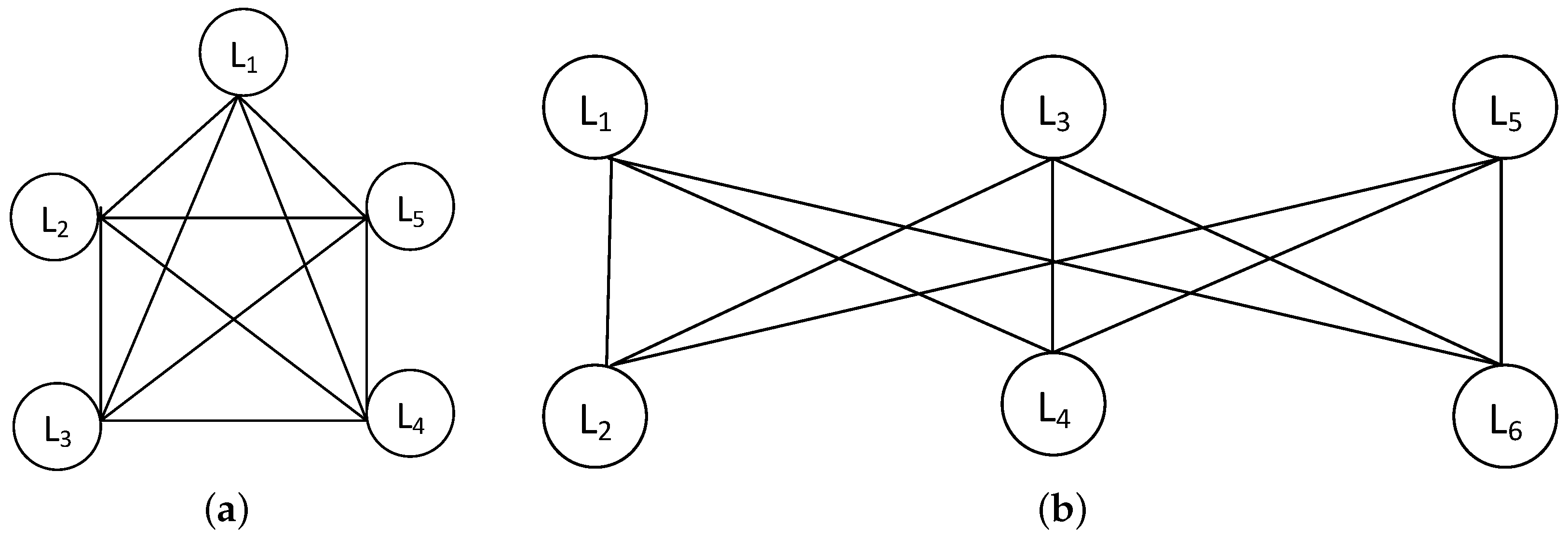
4.1. Conflict Graph and Planar Graph

We assume that the mesh routers in the WOBAN have identical transmission ranges, which is denoted as R. The interference range is assumed to be R R . Because of the broadcast nature of the wireless medium, the success of a transmission is greatly influenced by interferences from multiple sources. We represent such interference using conflict graph [40], which we describe using Figure 4.
Definition 1 (Conflict graph).
Each link i j in the connectivity graph is represented by a vertex in the conflict graph. The edges in between the vertices (say, A B and C D ) in the conflict graph represents that those links are within the interference range of each other in the connectivity graph.
We assume that a transmission from A to B is successful (in presence of RTS/CTS) if all the nodes located within R from either A or B refrain from transmission. For example, in Figure 4, C is in the interference range of B , thus there is an edge between A B and C D in the conflict graph.
Our objective is to assign different channels to the vertices of the conflict graph (which are links in the connectivity graph) that interfere each others. The problem is identical to the vertex coloring problem [41], which is defined as follows:
Definition 2 (Vertex coloring problem).
Assume that G = ( V , E ) is an undirected graph and C is the set of available colors. Then, the vertex coloring of G is a mapping π : V C such that, for any two vertices x and y, if ( x , y ) E , then π ( x ) π ( y ) . Thus, the vertex coloring is the assignment of colors to the vertices such that no two adjacent vertices share the same color.
The following definitions (or theorems) are also relevant while coloring or assigning channels to the conflict graph.
Definition 3 (Planar graph).
A planar graph [42] is a graph that can be embedded in a plane, i.e., a planar graph can be drawn in a plane such that their edges only intersect at their endpoints. The graphs that are not planar are called non-planar graphs.
Definition 4 (Four color theorem).
All planar graphs are four colorable [43].
We therefore extract the planar subgraph of the conflict graph and then color it with four colors.

4.2. Generating the Planar Subgraph of the Conflict Graph

After constructing the conflict graph, we use vertex deletion to get the planar subgraph of the conflict graph, which is described in Algorithm 1. We first check the planarity of the conflict graph G in linear time by using the Boyer and Myrvold planarity test [44]. If G is non-planar, we generate its planar subgraph of G as follows. The vertex with the highest degree is first removed from G and placed in genetic-colored-list (GCL). Then, the planarity condition is checked again on the remaining graph (lines 3–6 in Algorithm 1). This vertex deletion process is repeated until the remaining graph becomes planar. The vertices from the remaining graph are stored in a separate list called four-colored-list (FCL). On the other hand, GCL consists of the vertices that are removed from G to make it planar.
Algorithm 1 Function Vertex Deletion (Input graph G).
1:GCL = FCL = NULL;
2:Sort v i G in decreasing order of vertex degree;
3:while G ≠ PLANAR do
4:G = G\ v i , v i is of maximum degree in G;Vertex with highest degree is removed from G
5: GCL = GCL ∪ v i ;And placed in GCL
6:end while
7:FCL = G;Vertices of the planar graph G is stored in FCL
8:return GCL and FCL;

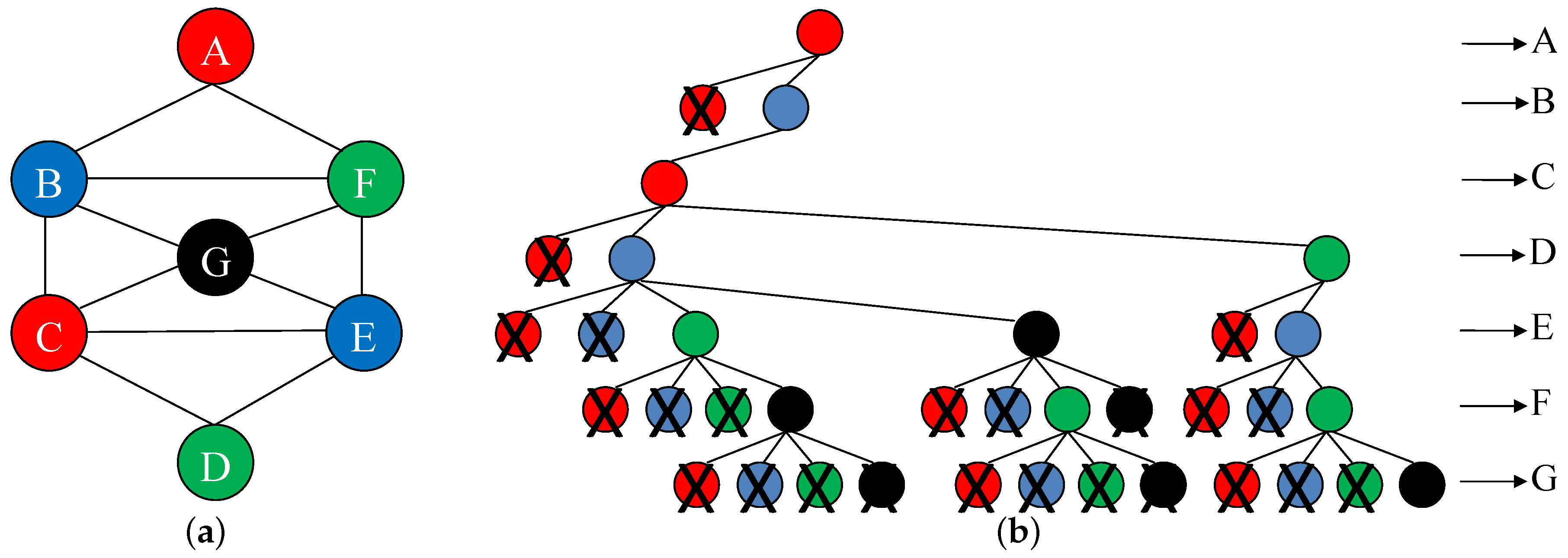
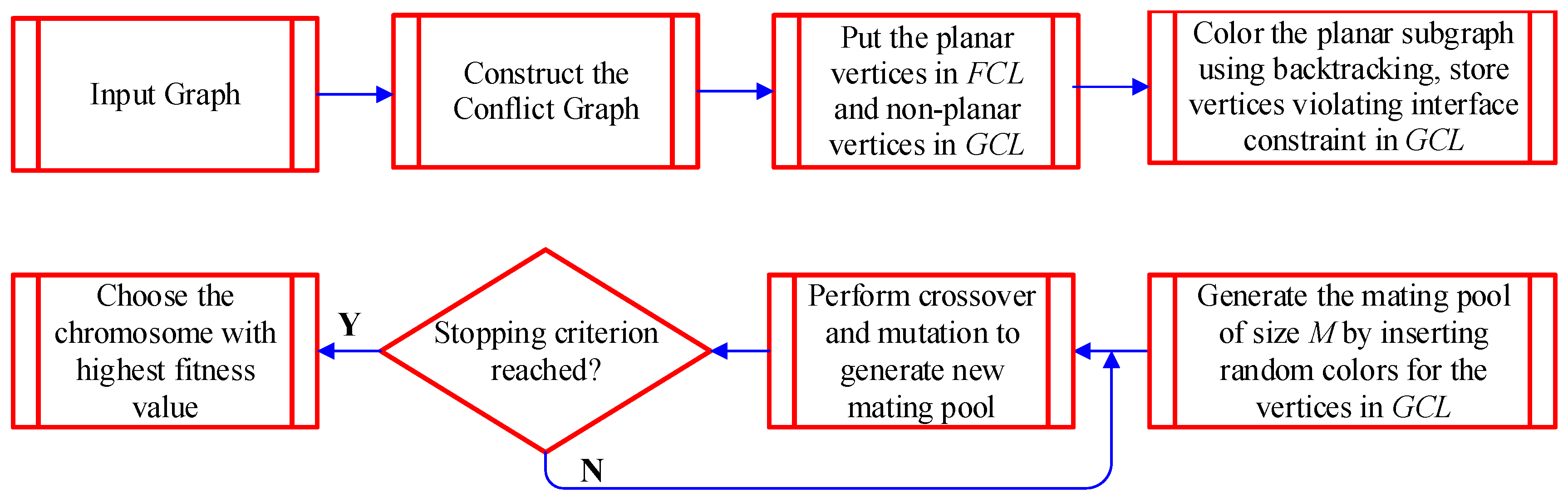
4.3. Our Proposed Algorithm for Coloring the Planar Subgraph

Let us denote the planar subgraph by G ˜ which consists of vertices in the FCL and their corresponding edges. According to the Four Color Theorem, G ˜ can be colored with 4 colors. Thus, we first color G ˜ with four colors by using a backtracking algorithm (line 4–line 23 in Algorithm 2). Figure 5 shows the example of graph coloring using backtracking.
Let us denote the available four colors as RED, BLUE, GREEN and BLACK which are indexed as 1, 2, 3, 4, respectively, in Algorithm 2. The vertices in FCL are denoted as { v 1 , v 2 , , v n } . Initially, all of the vertices can use any of the four colors. Without loss of generality, we start with vertex A and color it RED. Because of this assignment, all the adjacent vertices of A cannot use RED. Thus, B and F can only use BLUE, GREEN and BLACK. Assume that we proceed in this way and colors B , C , D , E and F are colored with BLUE, RED, BLUE, GREEN and BLACK, respectively. Now, there is no color left for G . Thus, we need to backtrack and then finally color D , E and F with GREEN, black and GREEN, respectively, and then color G with BLACK. This process guarantees a valid 4-coloring of G ˜ .
This vertex coloring of the conflict graph is then translated to color the links in the connectivity graph. Assume that the number of channels used by a node and its number of interfaces are C u and I, respectively. If C u > I at any node, then the interface constraint is violated. In that case, we select C u I links (which are vertices in the conflict graph) randomly around that node and add them to GCL (line 24). The GCL is next passed to the genetic algorithm (line 25).
The worst case complexity of backtracking grows exponentially with the number of vertices in the conflict graph. With four colors, the backtracking tree contains 1 + 4 + 4 2 + + 4 n 1 = 4 n 1 3 vertices. However, the number of solutions for a vertex coloring problem is significantly large, thus we do not need to explore the entire backtracking tree to get one valid solution. As studied in [45], a tree with n vertices can be colored in t ( t 1 ) n 1 ways, whereas a cycle of n vertices can be colored in ( t 1 ) n + ( 1 ) n ( t 1 ) ways, where t is the number of colors. As a conflict graph is composed of tree and cycles, searching a small fraction of the entire tree is sufficient to obtain a valid solution.
Algorithm 2 Algorithm for finding the color/channel assignment.
1:INPUT: Simple undirected graph G and the set of channels;
2:OUTPUT: Color assignment of G;
3:Vertex Deletion (G);To obtain the planar subgraph
4:All_nodes_colored = false;
5: v i = v 1 ;
6:Color( v 1 ) = 0;
7:while All_nodes_colored == false do
8:while Color( v i ) < 4 do
9:  if All_nodes_colored == true then
10:   break;
11:  end if
12:  Color( v i ) = Color( v i ) + 1;Color all vertices in G with at most 4 colors
13:  if ValidColor(Color( v i ), v i ) == true then
14:   if v i == v n then
15:    All_nodes_colored = true;
16:   else
17:     v i = v i + 1 ;
18:    Color( v i ) = 0;
19:   end if
20:  end if
21:end while
22: v i = v i 1 ;Backtrack if the vertex cannot be colored with 4 colors
23:end while
24:GCL = GCL ∪ (vertices violating interface-constraint);Vertices violating the interface-constraint are added to the GCL
25:Perform Genetic-Algorithm(GCL);
26:return G with vertex coloring;
The primary purpose of applying a backtracking strategy is to ensure that the genetic algorithm (which is computationally expensive) is performed on a lesser number of vertices. In our scheme, we only apply a genetic algorithm on the vertices in GCL, which is much lesser than the total number of vertices in the conflict graph and thus the genetic algorithm converges much faster. Notice that a graph is non-planar if it contains a subgraph that is a subdivision of the complete bipartite graph K 3 , 3 or the complete graph K 5 , which are shown in Figure 6. In general, a complete bipartite graph K m , n has m + n vertices and m n edges, whereas a complete graph K n has n vertices and n ( n 1 ) 2 edges. We use the following properties of vertex deletion to show its effectiveness in our proposed scheme.
Definition 5 (Vertex deletion).
The non-planar vertex deletion or vertex deletion v d ( G ) of a graph G is the smallest non-negative integer k such that the removal of k vertices from G produces the planar subgraph G ˜ [46]. The vertex deletions of the complete bipartite graph K m , n and complete graph K n are known and can be expressed as follows:
v d ( K m , n ) = m i n { m , n } 2 i f m i n { m , n } > 2 , = 0 otherwise ,
v d ( K n ) = n 4 i f n > 4 , = 0 otherwise .
Thus, in case of a K m , n graph, min { m , n } 2 vertex deletions are required to make the remaining graph planar [46]. For m = n > > 2 , this corresponds to ∼50% of vertex deletions. Consequently, the length of GCL also reduces by ∼50% which results in reduced convergence time of the genetic algorithm. However, in case of a complete graph K n , v d ( K n ) = n 4 . Thus, almost all the vertices will be added to the GCL, and the vertex deletion is less effective. However, in reality, the conflict graphs are hardly complete graphs. In that case, our proposed scheme will greatly reduce the convergence time of the genetic algorithm.

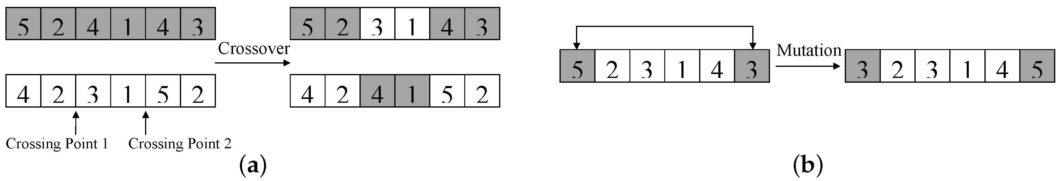
4.4. Our Proposed Genetic Algorithm for Channel Selection

Genetic algorithms are iterative optimization techniques influenced from the natural evolutionary process. In a genetic algorithm, the candidate solutions are embedded in chromosomes whose fitness values represent the quality of the corresponding solutions. The chromosomes are evolved from one generation to the other by using the survival of the fittest paradigm. In every generation, the offspring chromosomes are produced from the previous generation by using two genetic operators: crossover and mutation. The detailed description of the genetic algorithm is discussed as follows:
Genetic Representation: Let us assume that U is the number of vertices in GCL, and C is the number of available channels. We define a chromosome as a vector ( c 1 , c 2 , , c U ) , where c i is the channel/color assigned to vertex i. For example, with U = 6 , a chromosome 314,252 represents that the vertices { 1 , 2 , 3 , 4 , 5 , 6 } are assigned channels { 3 , 1 , 4 , 2 , 5 , 2 } , respectively. We assume that there are M chromosomes in a mating pool. The initial mating pool is generated by assigning random channels in between 1 and C to the vertices of the GCL, such that the interface constraint is satisfied. The fitness value of the chromosomes are then calculated based on their quality metric with the assigned channels.
Selection and Reproduction Process: We use the well known elitism based selection process, where the best M e < M chromosomes from one generation are placed directly in the next generation. This ensures that the best chromosomes are preserved in the next generation. For the rest of the M M e chromosomes, (a) we choose M M e parent chromosomes using a roulette wheel selection process (including the elitist ones), (b) which take part in crossover and mutation to generate M M e offspring chromosomes. We use two-point crossover as shown in Figure 7a. The mutation is carried out with a very low probability (assume to be 1% for our simulations), where we generate two random numbers in between 1 and U and interchange the colors of these vertices as shown in Figure 7b. After the crossover/mutation, if the interface constraint is violated in the offspring chromosomes, we merge a few channels randomly to meet the constraint.
The selection and reproduction process is repeated until the algorithm converges. Upon convergence, the chromosome/solution with the highest fitness value is chosen. This process is repeated for all the candidate routes, and finally the route with highest fitness value/quality is selected along with its channel assignment.
We now calculate the reduction of the convergence time of the genetic algorithm achieved by reducing the vertices in GCL (as the genetic algorithm is applied only on GCL). As mentioned in [47], the probability that the genetic algorithm converges at generation t of chromosome length l is given by
P ( t , l ) = 1 6 p 0 ( 1 p 0 ) M 1 2 M t l ,
where p 0 is the initial frequency of the allele and M is the population size (mating pool size). Assume a scenario where M = 1000 and p 0 = 0.5 . Now, to obtain 90% probability of convergence (i.e., P ( t , l ) = 0.9 ), a genetic algorithm takes 522 generations to converge with 200 bit chromosomes (i.e., l = 200 ). However, reducing the chromosome length by 50% (i.e., l = 100 ) ensures the algorithm to converge after 176 generations, which is about three times faster.

4.5. Complexity of the Proposed Channel Assignment Scheme

The average case complexity of the proposed channel assignment scheme is discussed as follows:
Conflict graph formation: If there are m edges in the connectivity graph, i.e., m vertices in the conflict graph, then, for any two of the m vertices, we need to check whether they are in the interfere each other or not. Thus, the conflict graph formation takes O ( m 2 ) time.
Vertex deletion: Next, we to calculate the complexity of vertex deletion. First, we need to sort m vertices based on their degree; this sorting takes O ( m log 2 m ) time. After that, for O ( m ) vertices, we need to check whether the deletion of that vertex makes the remaining graph planar or not. Checking of the planarity condition takes O ( m ) time based on a Boyer–Myrvold planarity test [44]. Thus, the total complexity of vertex deletion takes O ( m log 2 m + m 2 ) = O ( m 2 ) time.
Backtracking: The next stage is backtracking; for that, we need to visit L = 0 n 2 L 2 k L 2 L 2 k nodes on average based on [48] where k is the number of colors and n is the number of vertices in the planar subgraph. As in our case k = 4 , the backtracking takes O L = 0 n 2 L 2 20 L 8 times on average.
Genetic algorithm: Finally, we need to calculate the average complexity of genetic algorithm. First, let us calculate the number of generations the genetic algorithm takes to converge. If the expected number of generations is E [ i ] , then, from Equation (6), we get E [ i ] = t = 1 t P ( t , l ) . In each generation, it performs crossover and mutation that takes O ( U 2 ) and O ( U ) time, respectively, where U is the number of vertices in GCL. Thus, the average time complexity of genetic algorithm is given by E [ i ] O ( U 2 ) .
Thus, the average complexity of channel assignment scheme is given by O ( m 2 ) + O ( m 2 ) + O L = 0 n 2 L 2 20 L 8 + E [ i ] O ( U 2 ) = O ( m 2 ) + O L = 0 n 2 L 2 20 L 8 + E [ i ] O ( U 2 ) .

4.6. JRCA Routing Protocol

The detailed JRCA routing protocol can be illustrated by the following set of actions. JRCA is a reactive routing protocol that tries to maximize the packet delivery ratio while reducing the end-to-end latency [2].
Route Discovery: In JRCA, when a source router does not have a route to any destination (or gateway), it broadcasts a route request packet (RREQ) to its neighbors. The RREQ contains the following key fields:
〈RREQ ID, destination address, source address, number of active neighbors of the sender (A), accumulated POS on the current route ( P S ), accumulated delay in the current route ( T d ), timestamp〉
These quantities A, P S , T d and the timestamp are initialized at the source router: A is initialized to the number of active neighbors of the source, P S and T d are set to 1 and 0, respectively, and the timestamp is set to the time when the RREQ packet is generated. Every intermediate node updates the accumulated delay and POS based on the number of active neighbors of the previous node and its active interferers before forwarding it. The RREQ ID combined with the source address uniquely identifies a route request. This is required to ensure that the intermediate nodes rebroadcast a route request only once in order to avoid broadcast storms. If an intermediate node receives a RREQ more than once, it discards it. All intermediate nodes follow the same principle and forward the RREQ until it reaches the gateways. The timestamp is used to avoid the unnecessary flooding of RREQ packets.
Route Selection: The destinations (gateways) wait for the first N RREQ packets, which is assumed to be 10 in our simulations. Then, they (a) run backtracking and genetic algorithm on all the routes carried by the RREQ packets, (b) collaborate with each other and (c) choose the routes and channels that maximizes route quality Q. The node locations and their neighborhood information are used while calculating Q. After choosing the route with highest Q, the gateway that receives the best route (carried by RREQ) forwards a route reply packet (RREP) back on the same route. The RREP packet contains the following key fields:
〈source address, destination address, assigned channels of the interfaces, timestamp〉
The intermediate nodes (a) forward the RREP back to the source in the reverse path, (b) perform channel switching if required (conveyed in the RREP packet), and (c) update their routing table entry. The source after receiving the RREP starts sending the data packets via this route.
Route Maintenance: If a routing table entry is not used for a long time, that entry is erased. This is required to make the scheme robust against the temporal variation of the wireless channels. Thus, after a long time, if a source router needs a route to the gateway, it starts a new route discovery to find a good quality route.
In JRCA, we assume a dedicated control channel on which all nodes assign a NIC. This is the default channel which is mainly used to send RREQ and RREP packets. Other interfaces are switched between different data channels for data transmission. The overall scheme of JRCA is depicted in Figure 8.

5. Performance Evaluation of Our Routing Protocol

We evaluate the performance of JRCA using the network simulator–2 (ns2) [49]. The simulator is significantly modified at the physical and MAC layer to model the cumulative interference and carrier sensing based on cumulative received power. The simulator is also extended to equip each node with multiple radios that can switch between multiple orthogonal channels. We consider a static network consisting on 30 nodes that are placed in a uniform grid. Two of these nodes are chosen as gateways. The sources are selected randomly that generate UDP flows, each of them remain alive for 200 s. We assume the channel switching delay to be 0 for simplicity. The key parameters used in our simulations are listed in Table 3.
We compare JRCA with the single channel scheme as well as with a random channel selection based multi-channel scheme. We evaluate four key performance metrics: (a) the average network throughput, (b) packet delivery ratio, (c) end-to-end packet delay and (d) jitter. The results are shown in Figure 9, Figure 10 and Figure 11.

5.1. Comparison with Different Number of Flows

Figure 9 shows the performance of the schemes with different number of flows, where the number of channels is assumed to be 12. For Figure 9, we assume that the transmission rate is 185 KBps. From Figure 9, we can observe that JRCA performs significantly better than a single channel scheme in terms of throughput, delivery ratio, delay and jitter. With four NIC per router, JRCA improves the network throughput by about three times, compared to the single channel case. On the other hand, the packet delivery ratio improves by ∼40%, and the end-to-end delay is reduced to about six times. This significant improvement in delivery ratio is achieved as a result of reduced network interference due to efficient channel selections. On the other hand, using multiple channels also results in reduced channel contention with the neighboring transmitting nodes, which significantly reduces the end-to-end packet delay and jitter. These factors result in significant improvement in the network throughput.
From Figure 9, we can also observe that the network performance improves with the increase in the number of NICs. Due to efficient channel selection, JRCA achieves better network performance in comparison to random channel selection scheme. Compared to the random channel selection scheme, JRCA improves the network throughput by ∼20%. On the other hand, the packet delivery ratio is improved by ∼10% and the packet delay is almost halved because of better channel management in JRCA.

5.2. Comparison with Different Loads

Figure 10 shows the variations of the performance metrics with varying traffic load. The number of channels is assumed to be 12. The number of source routers are assumed to be 10 for Figure 10. Figure 10 also shows a significant improvement of the performance metrics in case of JRCA, as compared to the single channel and random channel selection scheme. The improvement in comparison to random channel selection scheme is less evident with light network load, however the difference clear (∼20% improvement in network throughput, and ∼40% reducing in traffic delay) when the traffic load increases. In the case of JRCA with four NICs, the network throughput increases almost linearly by about five times, when the traffic load increases from 35 KBps to 185 KBps. On the other hand, the traffic delay increases by ∼10 times, due to more channel access delay with a higher network load.

5.3. Comparison with Different Number of Channels

Figure 11 shows the performance comparison with the variation in the number of channels. For these set of figures, we assume 10 active sources with a transmission rate of 185 KBps. As expected, increasing the number of NICs improves the network performance because of reduced channel contention and network interference. With 4 NICs, the network throughput increases by ∼20%, whereas the delivery ratio improves by ∼10%, compared to the scenario with 2 NICs. The traffic delay also reduced by ∼3 times with higher number of NICs.
The results show that the JRCA improves the network throughput up to three times, while reduces the traffic delay by six times, in presence of 12 channels and four NICs. This establishes the effectiveness of our scheme in a multi-gateway, multi-channel WOBAN, with only a small increase in the complexity.

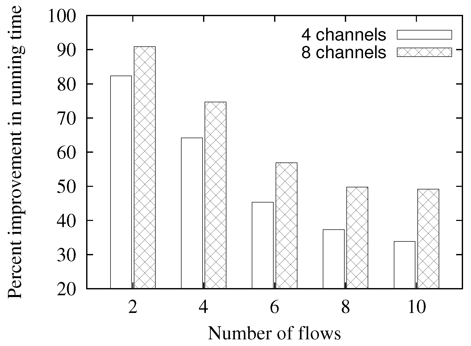
5.4. Comparison of Running Time

As mentioned earlier, for channel assignment, we use a genetic algorithm on a subgraph of the whole conflict graph to reduce convergence time. To validate this, we compare our scheme with the scheme that uses a genetic algorithm on all the vertices of the conflict graph, in an Intel Core2 Duo processor, running at 2 GHz. The result is shown in Figure 12, which shows that using backtracking on the planar subgraph and genetic algorithm on the remaining vertices of the conflict graph reduces the convergence time by upto 90%. This clearly shows the advantage of using the combination of backtracking and genetic algorithm for channel assignment, as discussed in Section 4. We can also observe that the improvement reduces with the increasing number of flows. This is because increasing in number of flows results in more vertices in the conflict graph, which makes it less planar. Thus more vertices go to the GCL which reduces the amount of improvement. The improvement also increases with the increase in number of channels.

6. Conclusions

WOBAN is a cost-effective and scalable solution for access networks that is a combination of high-capacity optical access and untethered wireless access. In this paper, we address a joint routing and channel assignment scheme in a multihop wireless portion of a WOBAN that requires solutions involving one or more cross-layer adaptations for achieving the required performance objectives. Such problems are characterized by a high degree of computational complexity that require special considerations to formulate tractable design approaches.
Our approach for the joint channel selection and routing problems in WOBANs includes development of a novel quality aware routing metric that can be applied when global network parameters are available, which is a valid assumption in a WOBAN framework; and development of a joint channel selection and route selection based on this quality metric. To address the computational complexity of the overall problem, we develop a combination of backtracking and genetic algorithm based channel assignment and router selection scheme. The proposed channel selection and routing protocol can improve the network throughput up to three times with twelve channels and four NICs, while reducing the traffic delay by six times, as demonstrated by our simulation results obtained from ns-2 implementations.

Author Contributions

The authors worked jointly in the development of the proposed JRCA protocol. A.P. was involved in the experimental work and data analysis. The paper was written collaboratively by A.P. and A.N.

Funding

This work was supported in part by NSF grant CNS-1117790.

Conflicts of Interest

The authors declare no conflict of interest.

Abbreviations

WOBANWireless-Optical Broadband-Access Networks
ONUOptical Network Unit
OLTOptical Line Terminal
COCentral Office
PONPassive Optical Network
EPONEthernet Passive Optical Network
GPONGigabit Passive Optical Network
BPONBroadband Passive Optical Network
TDMATime-Division Multiple Access
WDM-PONWavelength Division Multiplexing-Passive Optical Network
WiFiWireless Fidelity
WiMAXWorldwide Interoperability for Microwave Access
WMANWireless Metropolitan-Area Networks
RoFRadio-over-fiber
NICsNetwork Interface Cards
MACMedium Access Control
DCFDistributed Coordination Function
SINRSignal-to-interference-plus-noise ratio
POSProbability of Success
RTS/CTSRequest to Send/Clear to Send
ACKAcknowledgement
CSMA/CACarrier-Sense Multiple Access with Collision Avoidance
UDPUser Datagram Protocol
JRCAJoint Routing and Channel Assignment

References

  1. Global Internet Users and Penetration Rate. Available online: https://www.electronicdesign.com/communications/these-technologies-will-bring-gigabit-home (accessed on 12 October 2018).
  2. Pal, A.; Nasipuri, A. JRCA: A Joint Routing and Channel Assignment Scheme for Wireless Mesh Networks. In Proceedings of the IEEE International Performance Computing and Communications Conference (2011), Orlando, FL, USA, 17–19 November 2011. [Google Scholar]
  3. Wireless Networking: Understanding Various Wireless LAN Technologies. Available online: https://thecybersecurityman.com/2018/08/30/wireless-networking-understanding-various-wireless-lan-technologies/ (accessed on 12 October 2018).
  4. Sarkar, S.; Dixit, S.; Mukherjee, B. Hybrid Wireless-Optical Broadband-Access Network (WOBAN): A Review of Relevant Challenges. J. Lightw. Technol. 2007, 25, 3329–3340. [Google Scholar] [CrossRef]
  5. Pal, A.; Nasipuri, A. A Quality Aware Anycast Routing Protocol for Wireless Mesh Networks. In Proceedings of the IEEE SoutheastCon, Concord, NC, USA, 18–21 March 2010; pp. 451–454. [Google Scholar]
  6. Pal, A.; Nasipuri, A. GSQAR: A Quality Aware Anycast Routing Protocol for Wireless Mesh Networks. In Proceedings of the IEEE Global Telecommunications Conference GLOBECOM, Miami, FL, USA, 6–10 December 2010. [Google Scholar]
  7. Song, L.; Zheng, B. An Anycast Routing Protocol for Wireless Mesh Access Network. In Proceedings of the 2009 WASE International Conference on Information Engineering, Taiyuan, China, 10–11 July 2009; Volume 2, pp. 82–85. [Google Scholar] [CrossRef]
  8. Sharif, K.; Cao, L.; Wang, Y.; Dahlberg, T.A. A Hybrid Anycast Routing Protocol for Load Balancing in Heterogeneous Access Networks. In Proceedings of the 17th International Conference on Computer Communications and Networks, St. Thomas, Virgin Islands, USA, 3–7 August 2008; pp. 99–104. [Google Scholar]
  9. Lakshmanan, S.; Sivakumar, R.; Sundaresan, K. Multi-gateway association in wireless mesh networks. Ad Hoc Netw. 2009, 7, 622–637. [Google Scholar] [CrossRef] [Green Version]
  10. Nandiraju, D.; Santhanam, L.; Nandiraju, N.; Agrawal, D. Achieving Load Balancing in Wireless Mesh Networks Through Multiple Gateways. In Proceedings of the IEEE International Conference on Mobile Adhoc and Sensor Systems Conference (2006), Vancouver, BC, Canada, 9–12 October 2006; pp. 807–812. [Google Scholar]
  11. Marina, M.K.; Das, S.R. A topology control approach for utilizing multiple channels in multi-radio wireless mesh networks. In Proceedings of the International Conference on Broadband Networks, Boston, MA, USA, 7 October 2005; pp. 412–421. [Google Scholar] [Green Version]
  12. Subramanian, A.P.; Gupta, H.; Das, S.R.; Cao, J. Minimum Interference Channel Assignment in Multiradio Wireless Mesh Networks. IEEE Trans. Mob. Comput. 2008, 7, 1459–1473. [Google Scholar] [CrossRef] [Green Version]
  13. Das, A.K.; Vijayakumar, R.; Roy, S. Static Channel Assignment in Multi-radio Multi-Channel 802.11 Wireless Mesh Networks: Issues, Metrics and Algorithms. In Proceedings of the IEEE Global Telecommunications Conference GLOBECOM, San Francisco, CA, USA, 27 November–1 December 2006; pp. 1–6. [Google Scholar]
  14. Das, A.K.; Alazemi, H.M.K.; Vijayakumar, R.; Roy, S. Optimization models for fixed channel assignment in wireless mesh networks with multiple radios. In Proceedings of the Second Annual IEEE Communications Society Conference on Sensor and Ad Hoc Communications and Networks, Santa Clara, CA, USA, 26–29 September 2005; pp. 463–474. [Google Scholar] [Green Version]
  15. Kodialam, M.; Nandagopal, T. Characterizing the capacity region in multi-radio multi-channel wireless mesh networks. In Proceedings of the 11th Annual International Conference on Mobile Computing and Networking, Cologne, Germany, 28 August–2 September 2005; ACM Press: New York, NY, USA, 2005; pp. 73–87. [Google Scholar]
  16. Koshy, R.; Ruan, L. A Joint Radio and Channel Assignment (JRCA) Scheme for 802.11-Based Wireless Mesh Networks. In Proceedings of the 2009 IEEE Globecom Workshops, Honolulu, HI, USA, 30 November–4 December 2009. [Google Scholar]
  17. Raniwala, A.; Gopalan, K.; Cker Chiueh, T. Centralized Channel Assignment and Routing Algorithms for Multi-channel Wireless Mesh Networks. ACM Mob. Comput. Commun. Rev. 2004, 8, 50–65. [Google Scholar] [CrossRef]
  18. Raniwala, A.; Cker Chiueh, T. Architecture and algorithms for an IEEE 802.11-based multi-channel wireless mesh network. In Proceedings of the 24th Annual Joint Conference of the IEEE Computer and Communications Societies, Miami, FL, USA, 13–17 March 2005; pp. 2223–2234. [Google Scholar]
  19. Chen, J.; Jia, J.; Wen, Y.; Zhao, D.; Liu, J. A genetic approach to channel assignment for multi-radio multi-channel wireless mesh networks. In Proceedings of the ACM/SIGEVO Summit on Genetic and Evolutionary Computation, Shanghai, China, 12–14 June 2009; pp. 39–46. [Google Scholar]
  20. Fu, W.; Xie, B.; Wang, X.; Agrawal, D.P. Flow-Based Channel Assignment in Channel Constrained Wireless Mesh Networks. In Proceedings of the 17th International Conference on Computer Communications and Networks, St. Thomas, Virgin Islands, USA, 3–7 August 2008; pp. 424–429. [Google Scholar]
  21. Kyasanur, P.; Vaidya, N.H. Routing and link-layer protocols for multi-channel multi-interface ad hoc wireless networks. SIGMOBILE Mob. Comput. Commun. Rev. 2006, 10, 31–43. [Google Scholar] [CrossRef] [Green Version]
  22. Ramachandran, K.N.; Belding, E.M.; Almeroth, K.C.; Buddhikot, M.M. Interference-Aware Channel Assignment in Multi-Radio Wireless Mesh Networks. In Proceedings of the 25th IEEE International Conference on Computer Communications, Barcelona, Spain, 23–29 April 2006; pp. 1–12. [Google Scholar]
  23. Li, Y.; Wang, J.; Qiao, C.; Gumaste, A.; Xu, Y.; Xu, Y. Integrated Fiber-Wireless (FiWi) Access Networks Supporting Inter-ONU Communications. J. Lightw. Technol. 2010, 28, 714–724. [Google Scholar]
  24. Shaw, W.T.; Wong, S.W.; Cheng, N.; Kazovsky, L. MARIN Hybrid Optical-Wireless Access Network. In Proceedings of the Optical Fiber Communication Conference and Exposition and The National Fiber Optic Engineers Conference, Anaheim, CA, USA, 25–29 March 2007. [Google Scholar]
  25. Wong, S.-W.; Campelo, D.R.; Cheng, N.; Yen, S.-H.; Kazovsky, L.; Lee, H.; Cox, D.C. Grid Reconfigurable Optical-Wireless Architecture for Large Scale Municipal Mesh Access Network. In Proceedings of the IEEE Global Telecommunications Conference, Honolulu, HI, USA, 30 Novomber–4 December 2009. [Google Scholar]
  26. Kanonakis, K.; Tomkos, I.; Pfeiffer, T.; Prat, J.; Kourtessis, P. ACCORDANCE: A novel OFDMA-PON paradigm for ultra-high capacity converged wireline-wireless access networks. In Proceedings of the International Conference on Transparent Optical Networks, Munich, Germany, 27 June–1 July 2010. [Google Scholar]
  27. Kazovsky, L.; Wong, S.; Ayhan, T.; Albeyoglu, K.M.; Ribeiro, M.R.N.; Shastri, A. Hybrid Optical-Wireless Access Networks. Proc. IEEE 2012, 100, 1197–1225. [Google Scholar] [CrossRef]
  28. Sarigiannidis, A.; Iloridou, M.; Nicopolitidis, P.; Papadimitriou, G.I.; Pavlidou, F.; Sarigiannidis, P.G.; Louta, M.D.; Vitsas, V. Architectures and Bandwidth Allocation Schemes for Hybrid Wireless-Optical Networks. IEEE Commun. Surv. Tutor. 2015, 17, 427–468. [Google Scholar] [CrossRef]
  29. Sarkar, S.; Mukherjee, B.; Dixit, S. Optimum Placement of Multiple Optical Network Units (ONUs) in Optical-Wireless Hybrid Access Networks. In Proceedings of the Optical Fiber Communication Conference and Exposition and The National Fiber Optic Engineers Conference, Anaheim, CA, USA, 5–10 March 2006. [Google Scholar]
  30. Sarkar, S.; Mukherjee, B.; Dixit, S. Towards global optimization of multiple ONUs placement in hybrid optical-wireless broadband access networks. In Proceedings of the Joint International Conference on Optical Internet and Next Generation Network, Jeju, Korea, 9–13 July 2006; pp. 65–67. [Google Scholar]
  31. Sarkar, S.; Mukherjee, B.; Dixit, S. A mixed integer programming model for optimum placement of base stations and optical network units in a hybrid wireless-optical broadband access network (WOBAN). In Proceedings of the Wireless Communications and Networking Conference, Hong Kong, China, 11–15 March 2007. [Google Scholar]
  32. Sarkar, S.; Yen, H.; Dixit, S.S.; Mukherjee, B. A novel delay-aware routing algorithm (DARA) for a hybrid wireless-optical broadband access network (WOBAN). IEEE Netw. 2008, 22, 20–28. [Google Scholar] [CrossRef]
  33. Reaz, A.A.S.; Ramamurthi, V.; Sarkar, S.; Ghosal, D.; Dixit, S.S.; Mukherjee, B. CaDAR: An Efficient Routing Algorithm for Wireless-Optical Broadband Access Network. In Proceedings of the IEEE International Conference on Communications, Beijing, China, 19–23 May 2008; pp. 5191–5195. [Google Scholar]
  34. Reaz, A.S.; Ramamurthi, V.; Tornatore, M.; Sarkar, S.; Ghosal, D.; Mukherjee, B. Cost-efficient design for higher capacity hybrid wireless-optical broadband access network (WOBAN). Comput. Netw. 2011, 55, 2138–2149. [Google Scholar] [CrossRef]
  35. Pal, A.; Nasipuri, A. Performance analysis of IEEE 802.11 distributed coordination function in presence of hidden stations under non-saturated conditions with infinite buffer in radio-over-fiber wireless LANs. In Proceedings of the IEEE Workshop on Local & Metropolitan Area Networks, Chapel Hill, NC, USA, 13–14 October 2011; pp. 1–6. [Google Scholar]
  36. Pal, A.; Adimadhyam, S.; Nasipuri, A. QoSBR: A Quality Based Routing Protocol for Wireless Mesh Networks. In Proceedings of the International Conference on Distributed Computing and Networking, Kolkata, India, 3–6 January 2011; pp. 497–508. [Google Scholar]
  37. Pal, A.; Nasipuri, A. A Quality Based Routing Protocol for Wireless Mesh Networks. Pervasive Mob. Comput. 2011, 7, 611–626. [Google Scholar] [CrossRef]
  38. Garey, M. Computers and Intractability—A Guide to the Theory of NP-Completeness; W. H. Freeman & Co.: New York, NY, USA, 1990. [Google Scholar]
  39. Genetic Algorithms. Available online: http://www.obitko.com/tutorials/genetic-algorithms/ (accessed on 12 October 2018).
  40. Jain, K.; Padhye, J.; Padmanabhan, V.N.; Qiu, L. Impact of interference on multi-hop wireless network performance. In Proceedings of the International Conference on Mobile Computing and Networking, San Diego, CA, USA, 14–19 September 2003; pp. 66–80. [Google Scholar]
  41. Cormen, T.H.; Leiserson, C.E.; Rivest, R.L.; Stein, C. Introduction to Algorithms, 3rd ed.; The MIT Press: Cambridge, MA, USA, 2009. [Google Scholar]
  42. Trudeau, R.J. Introduction to Graph Theory; Dover Books on Mathematics; Dover: Mineola, NY, USA, 1994. [Google Scholar]
  43. Appel, K.; Haken, W. Every planar map is four colorable. Part I: Discharging. Ill. J. Math. 1977, 21, 429–490. [Google Scholar]
  44. Boyer, J.M.; Myrvold, W.J. On the cutting edge: Simplified O(n) planarity by edge addition. J. Gr. Algorithms Appl. 2004, 8, 241–273. [Google Scholar] [CrossRef]
  45. Hubai, T. The Chromatic Polynomial. Master’s Thesis, Eötvös Loránd University, Budapest, Hungary, 2009. [Google Scholar]
  46. Faria, L.; de Figueiredo, C.M.H.; Gravier, S.; Mendonca, C.F.; Stolfi, J. Nonplanar vertex deletion: Maximum degree thresholds for NP/Max SNP-hardness and a -approximation for finding maximum planar induced subgraphs. Electron. Notes Discret. Math. 2004, 18, 121–126. [Google Scholar] [CrossRef]
  47. Louis, S.J.; Rawlins, G.J.E. Predicting Convergence Time for Genetic Algorithms. Found. Genet. Algorithms 1992, 2, 141–161. [Google Scholar]
  48. Wilf, S. Backtrack: an O(1) Expected Time Algorithm for the Graph Coloring Problem. Inf. Process. Lett. 1984, 18, 119–121. [Google Scholar] [CrossRef]
  49. The Netwrok Simulator ns-2. Available online: http://www.isi.edu/nsnam/ns/ (accessed on 12 October 2018).
Figure 1. Access network architectures: (a) a PON for optical access; (b) a typical wireless mesh network for wireless access; (c) a WOBAN, which is a combination of PON and wireless mesh.
Jsan 07 00044 g001
Figure 2. Illustration of the effects of RTS/CTS packets to nodes located near a test link from S to D.
Jsan 07 00044 g002
Figure 3. WOBAN with multiple gateways.
Jsan 07 00044 g003
Figure 4. Illustration of (a) a five node connectivity graph and (b) its corresponding conflict graph.
Jsan 07 00044 g004
Figure 5. Illustration of (a) a seven node planar graph and (b) its corresponding backtracking tree for graph coloring.
Jsan 07 00044 g005
Figure 6. Illustration of (a) K 5 and (b) K 3 , 3 graphs.
Jsan 07 00044 g006
Figure 7. Genetic operations: illustration of (a) two-point crossover and (b) mutation.
Jsan 07 00044 g007
Figure 8. Joint route and channel assignment (JRCA) scheme.
Jsan 07 00044 g008
Figure 9. Comparison of (a) throughput (b) delivery ratio (c) delay (d) jitter with different number of flows for multi-channel WOBAN with multiple gateways.
Jsan 07 00044 g009
Figure 10. Comparison of (a) throughput (b) delivery ratio (c) delay (d) jitter with different loads for multi-channel WOBAN with multiple gateways.
Jsan 07 00044 g010
Figure 11. Comparison of (a) throughput (b) delivery ratio (c) delay (d) jitter with different number of channels for multi-channel WOBAN with multiple gateways.
Jsan 07 00044 g011
Figure 12. Percent improvement of running time in between pure genetic algorithm and the combination of backtracking and genetic algorithm based channel assignment.
Jsan 07 00044 g012
Table 1. IEEE 802.11 standards and non-overlapping channels [3].
StandardFrequencyBandwidthNon-Overlapping Channels
802.11b2.4 GHz20 MHz3 non-overlapping channels (channels 1, 6, and 11)
802.11a5 GHz20 MHz24 non-overlapping 20 MHz channels, and 12 non-overlapping 40 MHz channels
802.11g2.4 GHz20 MHz3 non-overlapping channels (channels 1, 6, and 11)
802.11n2.4/5 GHz20, 40 MHzIn 2.4 GHz band, there are 3 non-overlapping 20 MHz channels (channels 1, 6, and 11), and 1 non-overlapping 40 MHz channels (channel 3). In 5 GHz band, there are 24 non-overlapping 20 MHz channels, and 12 non-overlapping 40 MHz channels
802.11ac5 GHz20, 60, 80, 160 MHz24 non-overlapping 20 MHz channels, 12 non-overlapping 40 MHz channels, 6 non-overlapping 80 MHz channels, and 2 non-overlapping 160 MHz channels
Table 2. Table of notations.
n a / n b Active neighbors of the sender/receiver
T d Transmission delay
Δ R T S / Δ C T S Regions where the RTS/CTS packets for the test link are received
Δ C S Area where nodes can sense the transmission from sender S
λ Packet arrival rate
D A T A Data packet length (in bits)
BChannel bandwidth (in bits/seconds)
P S Probability of success
Q ( R ) Quality metric for route R
K m , n Complete bipartite graph with m + n vertices and m n edges
K n Complete graph of n vertices
CNumber of channels
INumber of interfaces
G ˜ Planar subgraph of G
MNumber of chromosomes in the mating pool
M e Number of elite chromosomes
Table 3. Simulation environment.
ParameterValuesParameterValues
Max queue length200Data packets size1000 bytes
Propagation ModelTwo Ray GroundTraffic GenerationExponential
Antenna gain0 dBTransmit power20 dBm
Noise floor−101 dBmSINRDatacapture10 dB
Bandwidth6 MbpsPowerMonitor Thresh−86.77 dBm
Average ON time0.5 sAverage OFF time0.5 s

