Abstract
Multiple-Input Multiple-Output (MIMO) systems are characterised by increased capacity and improved performance compared to the single-input single-output (SISO) systems. One of the main challenge in the design of MIMO systems is the detection of the transmitted signals due to the interference caused by the multiple simultaneously transmitted symbols from the multiple transmit antennas. Several detection techniques have been proposed in the literature in order to reduce the detection complexity, while maintaining the required quality of service. Among these low-complexity techniques is the Lattice Reduction (LR), which can provide good performance and significantly lower complexity compared to Maximum Likelihood (ML) detector. In this paper we propose to use the so-called Element-based Lattice Reduction (ELR) combined with K-Best detector for the sake of attaining a better Bit Error Ratio (BER) performance and lower complexity than the conventional Lenstra, Lanstra, and Lovasz (LLL) LR-aided detection. Additionally, we propose a hardware implementation for the ELR-aided K-Best detector for a MIMO system equipped with four transmit and four receive antennas. The ELR-aided K-Best detector requires an extra 18% increase in power consumption and an extra 20% in area overhead compared to a regular K-Best detector dispensing with ELR, where this increase in the hardware requirements is needed in order to achieve a 2 dB performance improvement at a bit error rate of 10−5.
1. Introduction
The demand for high data rate wireless services combined with the requirement for an increased Quality of Service (QoS) is driving the research and innovation in the wireless communications networks. Multiple-Input Multiple-Output (MIMO) techniques are characterised by an increased capacity as well as improved performance and hence the research in the MIMO design has seen a great interest for the last few years [1,2,3]. Recently, large-scale MIMOs have been proposed in order to scale up the MIMO gains [4,5], where, for example a large number of antennas can be implemented at the base station for supporting a large number of users.
MIMOs can be used to attain a multiplexing gain, where different transmit antennas transmit different symbols at the same time and using the same frequency. This increases the system throughput at the expense of having a more complex receiver for the sake of removing the interference imposed by the simultaneously transmitted symbols. As the number of transmit antennas increases, the detector complexity increases with the increase in the interference. Therefore, in large-scale MIMO systems, one of the main challenges is to reduce the detection complexity [6,7,8].
The Maximum Likelihood (ML) detector offers the best possible Bit Error Ratio (BER) performance at the expense of an increased complexity, which becomes impractical in terms of hardware implementation as the number of antennas and constellation size increases. On the other hand, linear detectors, such as the Zero Forcing (ZF) detector, are simple to implement, which is at the expense of a significant performance degradation compared to the ML detector. Hence, Lattice Reduction (LR) aided detectors have been proposed for MIMO systems in order to achieve a near-ML performance with significantly lower complexity [9,10]. Several algorithms have been proposed in the literature for performing Lattice Reduction such as the Lenstra, Lanstra, and Lovasz (LLL) algorithm [11], the Korkine-Zolotareff (KZ) algorithm [12] and the Element-based Lattice Reduction (ELR) algorithm [13]. The difference between these algorithms lies in their complexity, which also affects their performance when used for MIMO detection. The ELR algorithm has been proposed as a reduced complexity LR algorithm, while performing better than the LLL-aided MIMO detectors, when the number of antennas in significantly high [13]. In large scale MIMOs, the ELR algorithm requires less number of arithmetic operations for the LR basis update than the LLL algorithm [13]. LLL-aided linear detectors were employed in [10,14] to improve the performance of the conventional linear detectors dispensing with LR.
On the other hand, Sphere Decoder (SD) [15] was proposed in order to reduce the complexity of ML, while obtaining a near-ML performance. The SD searches only through those points that fall inside a sphere of radius r rather than do a full search as in the ML detector. There are many approaches to perform the tree search in the SD, where in this paper, we use the K-best algorithm [16,17]. LLL-aided K-best detector has been proposed in [18] in order to reduce the performance gap between the LR-aided detectors and their ML counterpart [18].
Recently, the ELR algorithm has been proposed for attaining an improved BER performance in large-scale MIMOs, while maintaining lower complexity compared to the LLL-aided detector [13]. Therefore, motivated by the results of [18], where the performance of the K-Best detector was improved by performing LR of the channel matrix before the detection, in [19] we proposed to improve the large-scale MIMO detection performance by applying the ELR algorithm with the K-Best detector, which we refer to as ELR-aided K-Best detector. We have shown in [19] that the ELR-aided K-Best detector is capable of achieving an improved BER performance compared to the LLL-aided K-Best detector, while requiring a significantly lower complexity.
In this paper, we propose an efficient hardware architecture for implementing the ELR-aided K-Best detector, where we consider the design trade-off of the operating frequency, chip area and energy efficiency [20]. In [21], an adaptive hardware implementation was proposed, that tries to minimize the energy consumed by using different detection methods including zero forcing and K-Best detection. The adaptation techniques were implemented with the aid of a control unit that selects the detector based on the received Signal to Noise Ratio (SNR). This design does indeed lower the power consumption of the decoder, but it comes at the cost of additional area requirement. Additionally, in [22] the authors focused on the parallelism of the K-Best detector, which can significantly improve the throughput and latency of the hardware implementation, where the different traversal paths of a K-Best tree search can be performed simultaneously. However, this also comes at the cost of more area as there are some replicated hardware blocks, which are run in parallel. Ref. [23] presented a LR-aided detector, which showed that LR aided detectors are viable in hardware and offer an improvement in BER at the cost of higher area overhead. Therefore, the main problem with the previous implementations, which were all for two transmit antenna and two receive antenna systems, is that the optimisations mainly came at the cost of an increased area requirement. Therefore, in this paper we propose a hardware efficient implementation of the ELR-aided K-Best detector, which is capable of significantly outperforming the K-Best detector, while requiring a small increase in the area overhead and power consumption compared to a K-Best detector dispensing with ELR.
Against this background the novel contributions of this paper can be summarized as follows:
- We analyze the ELR-aided K-Best detector for MIMO systems, where we consider the performance versus complexity trade-off of the design and compare this with the optimal ML detection. We show that the proposed design has a significantly lower complexity than the ML detector, while attaining near-ML performance.
- We then propose an efficient hardware architecture for implementing the ELR-aided K-Best detector, where we consider the design trade-off of the operating frequency, chip area and energy efficiency. We show that the proposed design requires a small increase in the area overhead and power consumption compared to a K-Best detector dispensing with ELR, while attaining a 2 dB performance improvement at a bit error rate of 10−5.
The rest of the paper is organized as follows. In Section 2 we present an overview of the MIMO system model used in this paper followed by Section 3, where the LR-aided MIMO detection is explained. In Section 3, we also present our proposed ELR-aided K-Best detector followed by the hardware implementation in Section 4. Finally, we present our conclusions in Section 5.
2. MIMO System Model
In this paper, we consider a MIMO system employing N transmit and M receive antennas as shown in Figure 1, where the different transmit antennas transmit different data streams in order to attain a multiplexing gain [24]. The channel is considered to be flat fading, where the channels between the different transmit and different receive antennas are considered to be spatially uncorrelated and are independent and identically distributed.
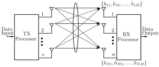
Figure 1.
MIMO system block diagram.
Let denote the transmitted complex symbol vector of size , where such that is drawn from a complex constellation of P-Quadrature Amplitude Modulation (P-QAM), where P is the constellation size. Furthermore, the channel can be described by a complex matrix of size , where changes independently from one frame to another. Therefore, the received signal can be expressed as:
where is the received complex signal vector of size and represents the complex Additive White Gaussian Noise (AWGN) vector of size with zero mean and variance . Given that there are different symbols transmitted from the different transmit antennas at the same time, these symbols will interfere with each other at the receiver side. Hence, the detector at the receiver should retrieve the transmitted vector from the received signal , which combines all the transmitted symbols.
In the previous paragraph, we have used the superscript c in the notations representing the transmitted symbol vector, received symbol vector, channel and noise in order to denote that these are complex valued. The complex model of (1) can be represented in an equivalent real model as follows:
where ℜ and ℑ represent the real and imaginary parts of a complex number, respectively. Additionally, (2) can be represented in the following form:
The equivalent real model of (3) has and both of size , while has a size of , and of size . Using the equivalent real model, each is drawn from the real constellation set of P-QAM as . For example the equivalent real model of a constellation is given by . In what follows, we use the equivalent real model for explaining the different detectors.
3. LR-Aided MIMO Detector Design
The ML detector requires to search through all possible constellation points of the transmitted symbol vector in (3) within the lattice , which can be expressed as . The ML detection requires high computational complexity. Hence, in order to reduce this complexity, LR-aided detectors were proposed in [9,10], where the channel matrix in transformed into its equivalent channel matrix , which is more orthogonal and better conditioned than [25,26]. The LR-aided detector uses the new orthogonal channel matrix , which gives more reliable estimation for the received signal than that of the detector that uses the original channel matrix [19].
The new matrix can be obtained by transforming the MIMO equation as follows [19]:
The new channel matrix is generated as , where is a uni-modular matrix having a determinant of and integer entries. Then, using the model in (4), the detector requires decoding from the reduced-lattice constellation and then recovers the original constellation point by (Note that integer set). Note that both and produce the same point in the lattice but is more orthogonal than . Various LR algorithms have been proposed in literature in order to produce the matrix, where in this paper we focus on the LLL algorithm [11] and the ELR algorithm [13].
3.1. LLL-Aided Detectors
We first present the LLL-aided detectors, where the LLL LR algorithm is used to obtain the matrix [11], which will result in a new channel matrix . Then, the new model in (4) is used in the detection process, where we first explain how the LLL is combined with the linear ZF detector and then we explain how the LLL can be combined with the K-Best detector.
In the LLL-aided ZF detector, the matrix is evaluated and then the new channel matrix is computed. Then, the equalisation matrix is obtained. Afterwards, is multiplied by the received signal using the transformed MIMO model presented in (4). The output of the LLL-aided ZF is and since , the original constellation symbols can be recovered by multiplying with after shifting, scaling and rounding as follows [10]:
where is a vector of all 1 entries.
On the other hand, in order to attain near-ML performance, ref. [18] showed that the performance of the K-Best detector can be improved by performing a LR preprocessing of the channel matrix prior to the K-Best detection. After obtaining the matrix using the LLL algorithm, the new channel matrix can be attained. Then, the K-Best detection is applied to the new model in (4), where the QR decomposition is performed for the new channel matrix as , with being an upper triangular matrix and a unitary matrix (A unitary matrix has the following property , where H represented the Hermitian transpose).
After the QR decomposition, (4) can be reshaped from to Then, the ML detection problem for can be expressed as:
where and . Note that , which is a shifted and scaled version of [27]. From (6), the K-Best detector requires performing a tree search to detect and then recovers the original symbols by multiplying with after rescaling and re-shifting as .
A further improvement to the LLL-aided K-Best detector has been proposed in [27] by combining with the Minimum Mean Square Error (MMSE) regularization, where the channel matrix is replaced with the extended matrix and the received signal vector is replaced with the extended as follows:
and then the same K-Best detection process described above is applied. This is referred to as LLL-aided MMSE K-Best detector and has an improved performance compared to the LLL-aided K-Best detector.
3.2. ELR-Aided Detectors
In Section 3.1 LLL-aided detectors have been described, which are capable of achieving significant performance improvement compared to detectors not using LR [10,14]. However, this performance improvement degrades gradually and starts to deviate from the ML performance as the number of antennas increases [13,18]. This is due to the fact that the LLL algorithm is less efficient in large-scale MIMO system [13,18]. Recently, Element-based Lattice Reduction (ELR) algorithm [13] has been proposed to perform lattice reduction for large-scale MIMO systems with an improved performance compared to the LLL algorithm, while also requiring lower complexity [13]. Furthermore, we have proposed in [19] an ELR-aided K-Best detector that is capable of outperforming the LLL-aided detectors when used for large-scale MIMO at a reduced complexity.
The ELR algorithm for evaluating the matrix is shown in Table 1. The ELR algorithm has been applied with ZF detector for large-scale MIMO in [13,28], where a significant performance improvement has been attained compared to the LLL-aided detectors.

Table 1.
ELR algorithm [28].
In [19], we proposed to further improve the performance of ELR-aided detectors by employing the ELR algorithm before the K-Best detection process for large-scale MIMO. Our proposed ELR-aided K-Best detector can achieve an improved BER performance compared to the LLL-aided detectors, while requiring significantly lower complexity. The ELR-aided K-Best detection process is similar to that described in Section 3.1 with the difference that it adopts the ELR algorithm described in Table 1 in order to produce the matrix used to obtain the new channel matrix .
The proposed ELR-aided K-Best detector can be further enhanced by employing MMSE regularization as described in Section 3.1 to obtain the ELR-aided MMSE K-Best detector. The above-proposed ELR-aided K-Best and ELR-aided MMSE K-Best detectors can perform better than the state-of-the-art detectors including LLL-aided K-Best and LLL-aided MMSE K-Best detectors, while at the same time requiring lower complexity. The reduction in the complexity is mainly due to the fact that the number of the arithmetic operations required by ELR algorithm for basis updates is lower than the LLL algorithm as explained in [13].
3.3. Performance Analysis
In this section, we present the performance analysis of the ELR-aided detectors, where we compare the BER as well as complexity of the ELR- and LLL-aided detectors. Then, we analyse the performance difference between the ELR-aided K-Best detector and the K-Best detector, which forms the basis for our hardware implementation proposed architecture in Section 4.
First, we compare the BER performance of the ELR-aided detectors with the benchmark techniques described in Section 3.1 using the LLL-aided detection, when employed to MIMO systems. This comparison is included in order to show the benefits of the proposed ELR-aided K-Best decoder design compared to its benchmarkers in large-scale MIMO systems. We performed Matlab simulation for a large-scale MIMO system employing transmit and receive antennas, while employing 64-QAM. In our simulations we considered Rayleigh fading channels, where the channels between the different transmit and receive antennas are independent. The simulation parameters are included in Table 2, where we have opted to use to compare with the results reported in [29]. Additionally, in the simulation set up, we have assumed the channel state information is perfectly estimated at the receiver and we also consider perfect synchronisation of the transmit antennas.

Table 2.
System parameters.
Figure 2 shows the BER performance comparison of the various decoding techniques (Note that in the figure we do not show the performance of the ML detector due to its extremely high complexity for simulation with our configuration). As shown in Figure 2 the BER performance of the ZF detector forms as an upper bound on the BER performance of the other detectors, while the ZF detector has the lowest computational complexity. When LR is combined with the ZF detection, Figure 2 shows that significant performance improvement can be attained compared to the ZF detector dispensing with LR. Additionally, it can be seen from Figure 2 that the ELR-aided ZF detector has a better performance that its LLL-aided counterpart. The aim of the LR-aided detectors is to attain a sub-optimal performance close to that of the ML, while requiring significantly lower complexity than the ML detector.
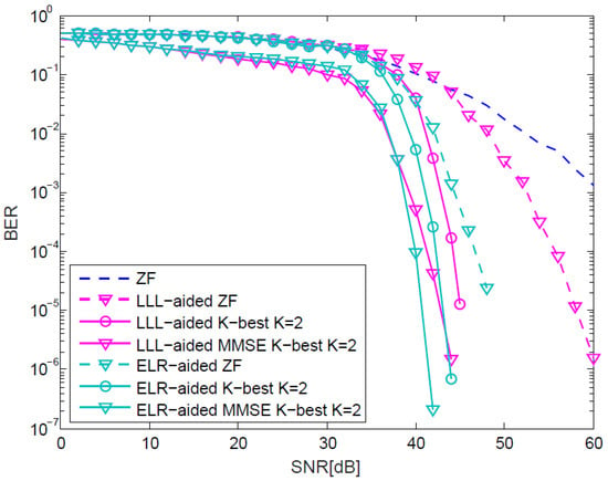
Figure 2.
BER performance of various LR-aided detectors over 200 × 200 MIMO system and using 64-QAM as a modulation scheme.
The simulation results in Figure 2 for the LLL-aided detectors show BER performance improvements for the simulated large-scale MIMO compared to the ZF performance. Additionally, the proposed ELR-aided detectors show performance improvement compared to their LLL-aided counterparts. For example, the proposed ELR-aided K-Best detector is capable of attaining a 2 dB performance gain compared to its LLL-aided counterpart at BER of . Additionally, the ELR-aided MMSE K-Best detector outperforms its LLL-aided counterpart by about 3 dBs at BER of . Explicitly, the ELR-aided detector requires lower SNR to attain any BER compared to the LLL-aided detector, which means that it requires lower transmit power.
After we have established that the ELR-aided detectors are capable of attaining an improved performance compared to their LLL-aided detectors, in the following we analyse the complexity difference between these detectors. We consider the complexity in terms of the number of arithmetic operations including real additions and real multiplications. Given that the detection techniques are the same in the ELR and LLL-aided detectors, we compare the complexity of the LLL and the ELR algorithms for performing the LR. Figure 3 shows the average number of arithmetic operations for the basis update in the LLL and ELR algorithms versus the number of MIMO transmit and receive antennas, where the plot assumes the same number of transmit and receive antennas. As shown in Figure 3, the ELR has a significantly lower number of arithmetic operations than the LLL algorithm, which is consistent for all number of antennas. The ELR requires nearly an order of magnitude less arithmetic operations that the LLL algorithm, as shown in Figure 3. Therefore, we can conclude that our proposed ELR-aided detectors will require significantly lower complexity than their LLL-aided counterparts, while at the same time achieving better performance.
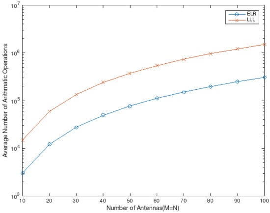
Figure 3.
Average number of arithmetic operations for basis updates of LLL and ELR algorithms versus the number of MIMO transmit and receive antennas [13].
Therefore, in our hardware implementation of the LR-aided K-Best detector we aim to utilise the ELR algorithm, which is capable of attaining a better performance and has a lower complexity. In Figure 4 we show the performance of the ML, K-Best and ELR K-Best detectors when applied to MIMO system employing four transmit and receive antennas. As shown in the Figure, the ELR-aided K-Best detector is capable of outperforming the K-Best detector and attains a closer-to-ML performance. Furthermore, in Figure 5 we show the SNR performance gap from the ML detector for the K-Best and ELR-aided K-Best detectors to attain a BER of . The performance gap is evaluated as the difference in the SNR required to attain a BER of between the two detectors and the ML detector for a variable number of transmit and receive antennas. As shown in Figure 5 the performance gap from ML of the ELR-aided K-Best detector is always smaller than that for the K-Best detector. In the following section we describe the hardware implementation of the ELR-aided K-Best detector when applied to a MIMO system utilising four transmit and four receive antennas.
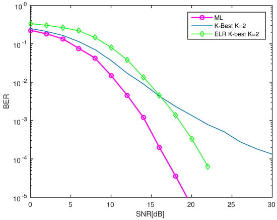
Figure 4.
BER performance of detectors over 4 × 4 MIMO system and using Binary Phase Shift Keying (BPSK) modulation scheme.
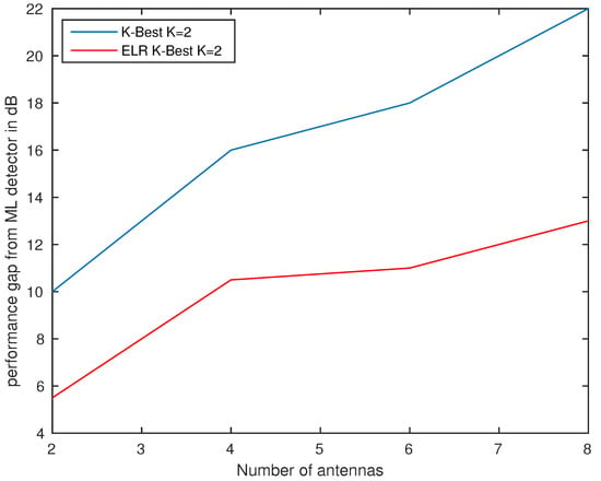
Figure 5.
SNR performance gap in dB from the ML detector to attain a BER of 10−5 of the K-Best and ELR K-Best detectors for a variable number of transmit and receive antennas.
4. Hardware Design
We have designed a hardware architecture for the above-described MIMO detector utilising four transmit and four receive antennas, which can be seen in Figure 6. The architecture of Figure 6 is based on the ELR-aided K-Best algorithm for a MIMO system utilising QAM and . We first developed a software model of the decoder using MATLAB, which was used for functional verification of the implementation and also used to produce the BER results in the previous sections. Then, we implemented the proposed architecture in “System Verilog”.
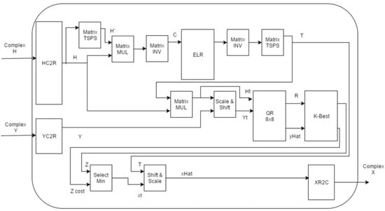
Figure 6.
Hardware Architecture of Element-based Lattice Reduction aided K-Best Detector.
The operation principles of the design are as follows. First, the decoder takes and as inputs, where in the considered MIMO system, is a vector of complex numbers and is a matrix of complex numbers. Therefore, in order to simplify the mathematical matrix operations in the hardware implementation, and are converted to a real vector and real matrix, respectively, using the YC2R and HC2R modules in Figure 6. After the complex-to-real matrix conversion shown in Figure 6 the matrix is produced, which is then followed by the ELR operation shown in Table 1. We have implemented a pipeline of three functional blocks shown in Figure 6, namely the ELR block which produces the matrix T, followed by a matrix inversion and then matrix transpose (TSPS) stage. This pipelining approach has helped to improve the throughput of this block and made it easier to test and debug its functionality. Afterwards, the received signal and the ELR-aided channel matrix are scaled and shifted as described in Section 3 and as shown in Figure 6. Then, QR decomposition is applied as described in Section 3, where the QR decomposition transforms a matrix into the product of an orthogonal matrix and an upper right triangular matrix . The QR decomposition is typically achieved using the Given Rotations algorithm [30].
In the proposed decoder, the QR decomposition is implemented using a systolic array of 36 elements of CORDIC operations. CORDIC stands for Coordinate Rotation Digital Computer and is an algorithm used to implement trigonometric functions in hardware. This is done by either CORDIC vectors or rotations. The main idea is to keep rotating a given vector by a reducing angle over and over again up to a certain accuracy [31]. For example, in the first iteration, the vector can be rotated by 45 degrees clockwise. If this overshoots, then the next rotation would be 22.5 degrees counterclockwise, otherwise if no overshooting occurs then 22.5 degrees are applied clockwise. This is repeated for a number of times specified by the designer. For the purposes of this project 15 stages were used to achieve higher accuracy.
After the QR decomposition, the decoder performs the K-Best detection based on a breadth-first tree search algorithm, which expands a fixed number of K nodes at each level. This can be implemented using a pipelined architectures. More details on this can be found in [17]. To reduce the complexity of the K-Best block, K was set to 2, which mean at each level of the tree search 2 out of 8 nodes are explored and this is shown to produce satisfactory results as shown in Section 3. Higher K values may improve the accuracy of the K-Best algorithm but at the expenses of more computational power and longer execution time. Then, after the K-Best operation, the (select min) block in Figure 6 finds the solution with the minimum costs, which is then shifted and scaled as shown in Figure 6 followed by complex-to-real transformation in order to recover the transmitted symbol x.
The choice of the word length can greatly affect the hardware cost of the detector and its BER performance, where longer word lengths would results in a better performance as well as higher hardware costs in terms of area overhead and energy consumption. Figure 7 shows the BER attained at SNR = 30 dB for a MIMO, while varying the word length. As shown in Figure 7, increasing the word length results in a reduced BER performance. Our experiments indicated that a word length of 9 bits would achieve the required performance, so it was adopted in our design.
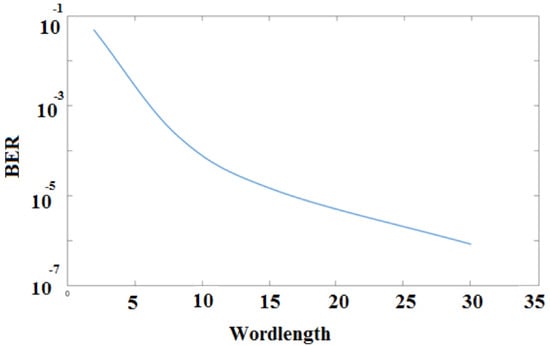
Figure 7.
The Effect of the word length on the BER Performance of Element-based Lattice Reduction aided K-Best Detector.
The design was modelled using “System Verilog” and implemented using 32 nm standard CMOS technology. In the following, we will provide more details on the design of the two main blocks in our proposed architecture, namely the Element-Based Lattice Reduction module and the QR decomposition module. Additionally, we will present a detailed analysis of the design overheads.
4.1. Hardware Implementation and Test of the Element-Based Lattice Reduction
The main body of the ELR algorithm was implemented using 12 states in hardware. First, T is initialized to the identity matrix and is initialized to all ones so that the condition of having equal to zeros in step 4 of the algorithm in Table 1 does not break from the loop. Following that entries on each row of C are divided by the equivalent row element from the matrix diagonal, e.g., C (1, 3) is divided by C (1, 1). The value of this operation is stored in . After traversing the entire C matrix, is checked to see of all of its values are zeros. If that condition is true then the ELR algorithm is done, otherwise the largest value in C and are found and then they are used to update matrix T and C as shown in steps 9–11 in Table 1. This process keeps repeating until the condition of being all zeros is met and then T is delivered as the output of the ELR block. In hardware T is then passed to a matrix transpose and matrix inverse blocks to perform step 13 of Table 1.
As described in Table 1, the ELR algorithm uses a while (true) loop and breaks out of it when a certain condition is met. This is generally undesirable and through initial testing of the algorithm it was determined that there are inputs for which this algorithm keeps looping forever. To solve this issue, a counter was added which is incremented at the end of each full iteration. If that counter reaches 20, then the algorithm will exit the while loop and use the current value of T as the output. This has shown to work fine as the final estimation is not affected much by this change. One final note on the algorithm is that when it takes up to 20 iterations, it is significantly the most computationally demanding block of the decoder and takes the largest number of clock cycles (up to 12,000 clock cycles). Additionally, two combinational blocks were designed to be used within the ELR block. Those were the max and rounding blocks which as their names suggest find the maximum number between a set of inputs and round a number up or down respectively.
Finally, in order to test and validate the design, simulations were run with different sets of inputs. These inputs were then compared to MATLAB simulations for verification. The test results showed correct functionality of the implemented hardware.
4.2. Hardware Implementation and Test of the QR decomposition
QR decomposition is a matrix decomposition, for example of a given matrix A, into Q and R which are an orthogonal matrix and an upper right triangular matrix, respectively. On the algorithmic level there are several ways to achieve this, but for a hardware implementation usually ‘Givens Rotations’ are used to achieve this with the use of CORDIC operations. In order to apply the Givens Rotations to an matrix, a systolic array was designed to accommodate the CORDIC vectoring and rotations. For the implementation of the proposed decoder the matrices were converted from complex to real, as shown in the design of Figure 8.
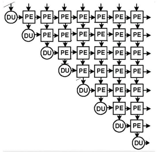
Figure 8.
8 × 8 Systolic Array Block Diagram for real numbers.
As shown Figure 8 there are 2 main types of blocks in the systolic array. The first is the delay unit (DU), which takes inputs from the northern port and passes it to the eastern port as output after a specified delay. This specific delay is basically the time required for a processing element (PE) to produce an output. The PE is a processing element, which is where the real operations are carried out. A PE block takes 2 data inputs and produces 2 data outputs as well as 2 control signal inputs and 2 control signal outputs. Then, depending on the mode decided by the control signal coming in from the western port, the PE block operates in vectoring mode or rotating mode. These modes differ for complex numbers and real numbers. Since our implementation is for real numbers as shown in Figure 8, we will discuss how the PE blocks operate for the real values. In vectoring mode, the PE block takes both inputs, x and y, and calculates the angle z as follows:
where
Then z is stored internally. Its outputs are the modulus of the inputs presented at the eastern port, and the southern port just gives out a zero. When the mode specifics CORDIC rotations, the inputs are multiplied by the angle z stored internally as mentioned earlier, and the rotated outputs x and y are presented at the eastern and southern ports respectively. To test the QR decomposition module, Modelsim waveforms were produced and compared to MATLAB results, which showed correct functionality of the implemented hardware.
4.3. Design Analysis
To estimate the complexity of the design, we have estimated the area and power consumption of the main blocks as detailed in Table 3.

Table 3.
Area and Power Analysis for Proposed Decoder using 32 nm CMOS Technology at 100 MHz.
As it can be seen, the QR decomposition block consumes the largest area of the design. This is because for 8 × 8 decomposition 26 processing elements and 8 delay units were used. As mentioned previously, the decision was made to simplify the design by converting the inputs from complex to real. However, if QR decomposition for 4 × 4 matrix would be used, this could save up around 25% of the area consumed by the QR block. Unfortunately, this optimization in the QR block would lead to more area overhead in other parts of the design including the matrix multiplication and inverting blocks as well as normal embedded multipliers used in other blocks. As a result, it has been concluded that 8 × 8 QR decomposition is necessary and this cost of area is actually the best option. Other modules that take up a significant area in the design are the K-best and ELR blocks. Then concerning the power, the QR block consumes the most power due its size and complexity. Additionally, the ELR and K-best blocks consume a reasonable chunk of the power due to similar reasons. However, it is noticeable that the ‘scale and shift’ and the ‘shift and scale’ blocks consume power at the same level as the ELR and K-best blocks. This is due to the use of many multipliers and shifters in order to carry out the desired operations in those blocks.
Finally, Area and power costs are estimated for both the proposed detector and for a conventional K-Best design [17], where we summarise the overall results in Table 4. In Table 4, we have included the attainable BER achieved at a SNR=30 dB, while we have shown previously that the ELR-aided detector requires lower SNR to attain any BER compared to the detector dispensing with ELR. Hence, the results in Table 4 can be extended to any SNR to show that at any SNR the ELR-aided detector attains a lower BER. This can be extended as follows: given a target BER, the ELR-aided detector will require lower SNR to attain the target BER and hence a lower transmit power compare with the detector not using the ELR. The results indicates that the proposed design incurs 20% more area and consumes 18% more power compared to the conventional design dispensing with ELR, but this may be a small price to pay given the significant increase in the BER performance described in Section 3.

Table 4.
Comparison of Hardware Cost Metrics between K-best and ELR-aided K-best MIMO detection (Operation Frequency 100 MHz, SNR = 30 dB).
5. Conclusions
In this paper, we proposed an ELR-aided K-Best detector with its hardware implementation, that is capable of improving the performance of the LR-aided K-Best detectors for MIMO systems. Our proposed ELR-aided detectors are capable of outperforming their benchmark techniques, while requiring significantly lower complexity. Explicitly, the ELR-aided detectors are capable of attaining around 3.5 dB performance improvement at BER of 10−5 compared to the K-Best detector when considering a MIMO system with 4 transmit and 4 receive antennas. A hardware implementation of the proposed ELR-aided K-Best detector has been developed and verified using 32 nm standard CMOS technology. Our cost analysis indicate that the performance gains are at the expense of an increase in power consumption and area overhead by 18% and 20%, respectively, compared to the conventional K-Best detector dispensing with LR.
Author Contributions
M.E.-H. contributed to the decoder algorithm design, while B.H. and A.H. contributed to the hardware design.
Conflicts of Interest
The authors declare no conflict of interest.
References
- El-Hajjar, M.; Hanzo, L. Multifunctional MIMO systems: A combined diversity and multiplexing design perspective. IEEE Wirel. Commun. 2010, 17, 73–79. [Google Scholar] [CrossRef]
- Zheng, K.; Zhao, L.; Mei, J.; Shao, B.; Xiang, W.; Hanzo, L. Survey of Large-Scale MIMO Systems. IEEE Commun. Surv. Tutor. 2015, 17, 1738–1760. [Google Scholar] [CrossRef]
- Hanzo, L.; El-Hajjar, M.; Alamri, O. Near-Capacity Wireless Transceivers and Cooperative Communications in the MIMO Era: Evolution of Standards, Waveform Design, and Future Perspectives. Proc. IEEE 2011, 99, 1343–1385. [Google Scholar] [CrossRef]
- Marzetta, T. Noncooperative Cellular Wireless with Unlimited Numbers of Base Station Antennas. IEEE Trans. Wirel. Commun. 2010, 9, 3590–3600. [Google Scholar] [CrossRef]
- Zhang, J.; Zhang, B.; Chen, S.; Mu, X.; El-Hajjar, M.; Hanzo, L. Pilot Contamination Elimination for Large-Scale Multiple-Antenna Aided OFDM Systems. IEEE J. Sel. Top. Signal Process. 2014, 8, 759–772. [Google Scholar] [CrossRef]
- Yapıcı, Y.; Guvenc, I.; Kakishima, Y. A MAP-Based Layered Detection Algorithm and Outage Analysis over MIMO Channels. IEEE Trans. Wirel. Commun. 2017, arXiv:1710.01189. [Google Scholar]
- Jeon, Y.S.; Lee, N.; Hong, S.N.; Heath, R.W. One-Bit Sphere Decoding for Uplink Massive MIMO Systems with One-Bit ADCs. IEEE Trans. Wirel. Commun. 2018, arXiv:1709.04163. [Google Scholar]
- Yang, S.; Hanzo, L. Fifty Years of MIMO Detection: The Road to Large-Scale MIMOs. IEEE Commun. Surv. Tutor. 2015, 17, 1941–1988. [Google Scholar] [CrossRef]
- Windpassinger, C.; Fischer, R. Low-complexity near-maximum-likelihood detection and precoding for MIMO systems using lattice reduction. In Proceedings of the IEEE Information Theory Workshop, Paris, France, 31 March–4 April 2003; pp. 345–348. [Google Scholar]
- Ma, X.; Zhang, W. Performance analysis for MIMO systems with lattice-reduction aided linear equalization. IEEE Trans. Commun. 2008, 56, 309–318. [Google Scholar]
- Lenstra, A.; Lenstra, H.W., Jr.; Lovász, L. Factoring polynomials with rational coefficients. Math. Ann. 1982, 261, 515–534. [Google Scholar] [CrossRef]
- Agrell, E.; Eriksson, T.; Vardy, A.; Zeger, K. Closest point search in lattices. IEEE Trans. Inf. Theory 2002, 48, 2201–2214. [Google Scholar] [CrossRef]
- Zhou, Q.; Ma, X. Element-Based Lattice Reduction Algorithms for Large MIMO Detection. IEEE J. Sel. Areas Commun. 2013, 31, 274–286. [Google Scholar] [CrossRef]
- Gan, Y.H.; Mow, W.H. Complex lattice reduction algorithms for low-complexity MIMO detection. In Proceedings of the IEEE Global Telecommunications Conference, St. Louis, MO, USA, 28 November–2 December 2005; Volume 5. [Google Scholar]
- Viterbo, E.; Boutros, J. A universal lattice code decoder for fading channels. IEEE Trans. Inf. Theory 1999, 45, 1639–1642. [Google Scholar] [CrossRef]
- Guo, Z.; Nilsson, P. Algorithm and implementation of the K-best sphere decoding for MIMO detection. IEEE J. Sel. Areas Commun. 2006, 24, 491–503. [Google Scholar]
- Bello, I.A.; Halak, B.; El-Hajjar, M.; Zwolinski, M. A Survey of VLSI Implementations of Tree Search Algorithms for MIMO Detection. Circuits Syst. Signal Process. 2016, 35, 3644–3674. [Google Scholar] [CrossRef]
- Qi, X.F.; Holt, K. A Lattice-Reduction-Aided Soft Demapper for High-Rate Coded MIMO-OFDM Systems. IEEE Signal Process. Lett. 2007, 14, 305–308. [Google Scholar] [CrossRef]
- Toma, O.H.; El-Hajjar, M. Element-based Lattice Reduction aided K-Best detector for large-scale MIMO systems. In Proceedings of the IEEE 17th International Workshop on Signal Processing Advances in Wireless Communications (SPAWC), Edinburgh, UK, 3–6 July 2016; pp. 1–5. [Google Scholar]
- Mohamed, M.I.A.; Mohammed, K.; Daneshrad, B. Energy Efficient Programmable MIMO Decoder Accelerator Chip in 65-nm CMOS. IEEE Trans. Very Large Scale Integr. (VLSI) Syst. 2014, 22, 1481–1490. [Google Scholar] [CrossRef]
- Halak, B.; El-Hajjar, M.; Hu, Q.; Lu, Y.; Li, Q.; Qiang, Y. Energy-efficient adaptive MIMO decoders. In Proceedings of the Science and Information Conference (SAI), London, UK, 28–30 July 2015; pp. 1140–1143. [Google Scholar]
- El-Aziz, M.M.A.; Seddik, K.G.; Elezabi, A.; Nafie, M. Performance and complexity comparison of near-optimal MIMO decoders. In Proceedings of the 2013 Asilomar Conference on Signals, Systems and Computers, Pacific Grove, CA, USA, 3–6 November 2013; pp. 500–504. [Google Scholar]
- Liu, L.; Löfgren, J.; Nilsson, P.; Öwall, V. VLSI Implementation of a Soft-Output Signal Detector for Multimode Adaptive Multiple-Input Multiple-Output Systems. IEEE Trans. Very Large Scale Integr. (VLSI) Syst. 2013, 21, 2262–2273. [Google Scholar] [CrossRef]
- Hanzo, L.; Alamri, O.; El-Hajjar, M.; Wu, N. Near-Capacity Multi-Functional MIMO Systems: Sphere-Packing, Iterative Detection and Cooperation; Wiley-IEEE Press: Chichester, UK, 2009. [Google Scholar]
- Ling, C. On the Proximity Factors of Lattice Reduction-Aided Decoding. IEEE Trans. Signal Process. 2011, 59, 2795–2808. [Google Scholar] [CrossRef]
- Silvola, P.; Hooli, K.; Juntti, M. Suboptimal soft-output MAP detector with lattice reduction. IEEE Signal Process. Lett. 2006, 13, 321–324. [Google Scholar] [CrossRef]
- Zhou, Q.; Ma, X. An improved LR-aided K-best algorithm for MIMO detection. In Proceedings of the International Conference on Wireless Communications Signal Processing (WCSP), Huangshan, China, 25–27 October 2012; pp. 1–5. [Google Scholar]
- Zhou, Q.; Ma, X. Designing low-complexity detectors for generalized SC-FDMA systems. In Proceedings of the 45th Annual Conference on Information Sciences and Systems (CISS), Baltimore, MD, USA, 23–25 March 2011; pp. 1–6. [Google Scholar]
- Chockalingam, A.; Rajan, B.S. Large MIMO Systems; Cambridge University Press: Cambridge, UK, 2014. [Google Scholar]
- Munoz, S.D.; Hormigo, J. High-Throughput FPGA Implementation of QR Decomposition. IEEE Trans. Circuits Syst. II Express Briefs 2015, 62, 861–865. [Google Scholar] [CrossRef]
- Renardy, A.P.; Ahmadi, N.; Fadila, A.A.; Shidqi, N.; Adiono, T. FPGA implementation of CORDIC algorithms for sine and cosine generator. In Proceedings of the 2015 International Conference on Electrical Engineering and Informatics (ICEEI), Denpasar, Indonesia, 10–11 August 2015; pp. 1–6. [Google Scholar]
© 2018 by the authors. Licensee MDPI, Basel, Switzerland. This article is an open access article distributed under the terms and conditions of the Creative Commons Attribution (CC BY) license (http://creativecommons.org/licenses/by/4.0/).