
Colorful Textile Antennas Integrated into Embroidered Logos


Abstract
:
1. Introduction
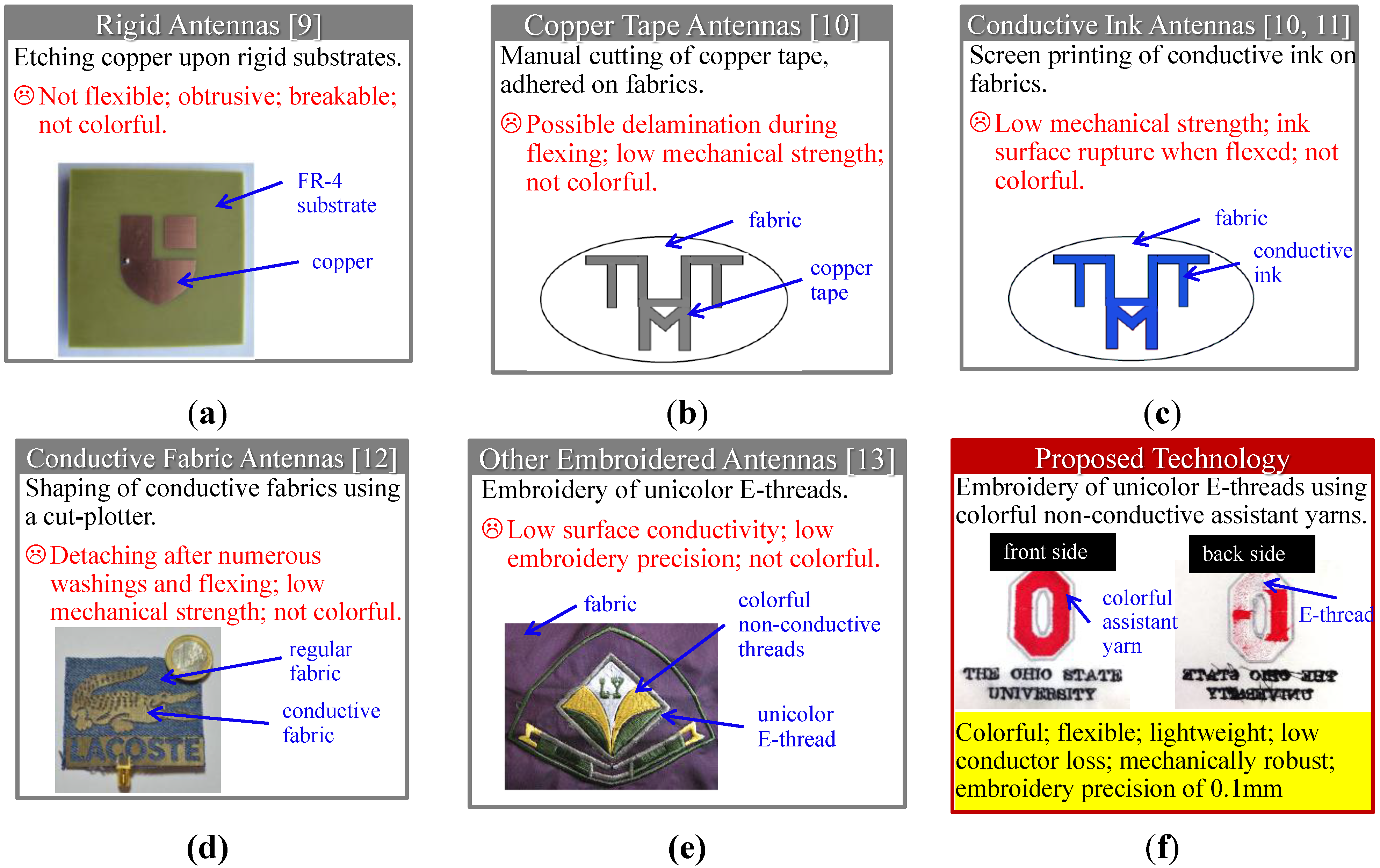
2. Embroidery Process for Colorful Textile Antennas
- 1)
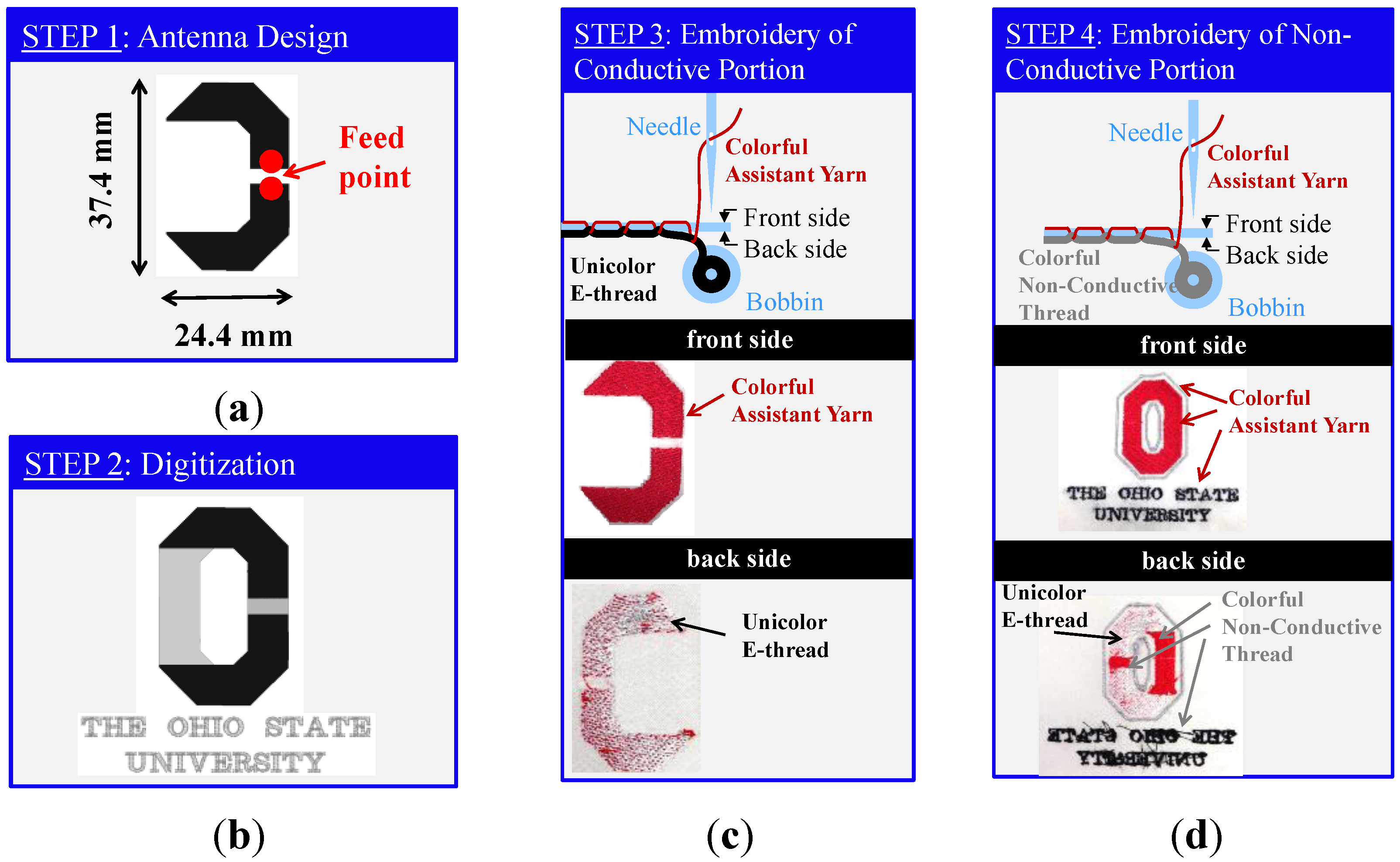
- Antenna design. An antenna design is developed to satisfy pre-specified performance criteria, including gain, bandwidth, size and operational frequency. This can be done via any desired computational or analysis method (see Figure 2a).
- 2)
- Digitization. The desired logo or aesthetic shape, and the back-side antenna are digitized and put into the embroidery machine’s format for loading. Referring to Figure 2b, the black color indicates the conductive portion of the logo (viz. the antenna), while the grey color indicates the non-conductive section (viz. the portion that surrounds the antenna to form the desired shape). The Computer Aided Design (CAD) file imported into the embroidery machine software contains the identification of the front and back side of the pattern in digital format.
- 3)
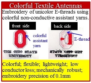
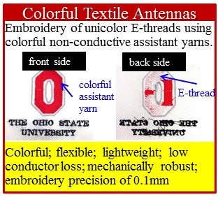
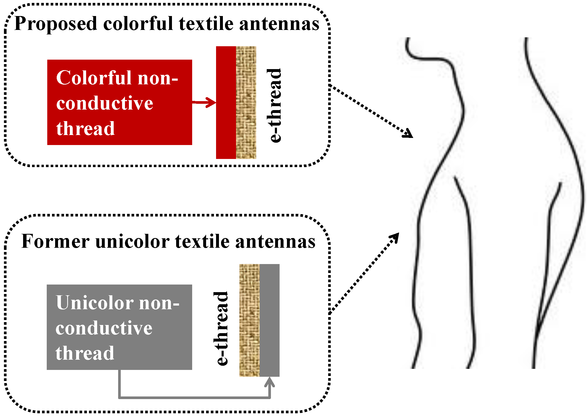
- Embroidery of conductive part. After loading the CAD file, the automated embroidery process is executed to ‘print’ the conductive parts of the logo; that is the antenna shown in black color in Figure 2b. To do so, the e-thread is placed inside the bobbin case of the embroidery machine. Concurrently, a colorful assistant yarn is threaded through the needle of the embroidery machine and used to ‘couch’ the e-thread on the fabric (see Figure 2c). As a result, the conductive portion of the logo becomes part of the colorful front side of the fabric. But in effect, the unicolor antenna formed by the conductive e-thread lies on the back side.
- 4)
- Embroidery of non-conductive part. The automated embroidery process is subsequently repeated for embroidering the non-conductive part of the logo. In this case, a non-conductive thread is placed inside the bobbin case of the embroidery machine. The colorful assistant yarn is used to ‘couch’ this non-conductive thread onto the fabric (see Figure 2d). Again, the colorful yarn appears in the front side of the fabric, while the non-conductive thread lies on the back side. This implies that the non-conductive thread fills in the design area not covered by Step 3. That is, Steps 3 and 4 complement each other to embroider the conductive and non-conductive parts of the entire logo.

3. Validation of a Colorful Textile Dipole Antenna as Part of the OSU Logo

4. Conclusions
Acknowledgments
Author Contributions
Conflicts of Interest
References
- Xu, Z.; Kaufmann, T.; Fumeaux, C. Wearable textile shielded stripline for broadband operation. IEEE Microw. Wirel. Compon. Lett. 2014, 24, 566–568. [Google Scholar] [CrossRef]
- Yilmaz, T.; Foster, R.; Hao, Y. Detecting vital signs with wearable wireless sensors. Sensors 2010, 10, 10837–10862. [Google Scholar] [CrossRef] [PubMed] [Green Version]
- Koski, K.; Vena, A.; Sydanheimo, L.; Ukkonen, L.; Rahmat-Samii, Y. Design and implementation of electro-textile ground planes for wearable UHF RFID patch tag antennas. IEEE Antennas Wirel. Propag. Lett. 2013, 12, 964–967. [Google Scholar] [CrossRef]
- Tsolis, A.; Whittow, A.G.; Alexandridis, A.A.; Vardaxoglou, J.C. Embroidery and related manufacturing techniques for wearable antennas: challenges and opportunities. Electronics 2014, 3, 314–338. [Google Scholar] [CrossRef] [Green Version]
- Stoppa, M.; Chiolerio, A. Wearable electronics and smart textiles: A critical review. Sensors 2014, 14, 11957–11992. [Google Scholar] [CrossRef] [PubMed]
- Wang, Z.; Zhang, L.; Bayram, Y.; Volakis, J.L. Embroidered conductive fibers on polymer composite for conformal antennas. IEEE Trans. Antennas Propag. 2012, 60, 4141–4147. [Google Scholar] [CrossRef]
- Wang, Z.; Lee, L.Z.; Psychoudakis, D.; Volakis, J.L. Embroidered multiband body-worn antenna for GSM/PCS/WLAN communications. IEEE Trans. Antennas Propag. 2014, 62, 3321–3329. [Google Scholar] [CrossRef]
- Kiourti, A.; Volakis, J.L. High-geometrical-accuracy embroidery process for textile antennas with fine details. IEEE Antennas Wirel. Propag. Lett. 2015, 14, 1474–1477. [Google Scholar] [CrossRef]
- Whittow, W.G. Antenna emblems reshaped as icons and aesthetic logos (aerial). Microw. Opt. Technol. Lett. 2013, 55, 1711–1714. [Google Scholar] [CrossRef]
- ElMahgoub, K.; Elsherbeni, T.; Yang, F.; Elsherbeni, A.Z.; Sydanheimo, L.; Ukkonen, L. Logo-antenna based RFID tags for advertising application. ACES J. 2010, 25, 174–181. [Google Scholar]
- Tribe, J.; Oyeka, D.; Batchelor, J.; Kaur, N.; Segura-Velandia, D.; West, A.; Kay, R.; Vega, K.; Whittow, W. Tattoo antenna temporary transfers operating on-skin (TATTOOS). In Design, User Experience, and Usability: Users and Interactions; Springer: Los Angeles, CA, USA, 2015; Volume 9187, pp. 685–695. [Google Scholar]
- Monti, G.; Corchia, L.; Tarricone, L. Textile logo antennas. In Proceedings of the 14th Mediterranean Microwave Symposium, Marrakech, Morocco, 12–14 December 2014; pp. 1–5.
- Choi, J.H.; Kim, Y.; Lee, K.; Chung, Y.C. Various wearable embroidery RFID tag antenna using electro-thread. In Proceedings of IEEE International Symposium on Antennas and Propagation, San Diego, CA, USA, 5–11 July 2008; pp. 1–4.
- Kiourti, A.; Volakis, J.L. Fabrication of textile antennas and circuits with 0.1 mm precision. IEEE Antennas Wirel. Propag. Lett. 2015. [Google Scholar] [CrossRef]
© 2015 by the authors; licensee MDPI, Basel, Switzerland. This article is an open access article distributed under the terms and conditions of the Creative Commons Attribution license (http://creativecommons.org/licenses/by/4.0/).
Share and Cite
Kiourti, A.; Volakis, J.L. Colorful Textile Antennas Integrated into Embroidered Logos. J. Sens. Actuator Netw. 2015, 4, 371-377. https://doi.org/10.3390/jsan4040371
Kiourti A, Volakis JL. Colorful Textile Antennas Integrated into Embroidered Logos. Journal of Sensor and Actuator Networks. 2015; 4(4):371-377. https://doi.org/10.3390/jsan4040371
Chicago/Turabian StyleKiourti, Asimina, and John L. Volakis. 2015. "Colorful Textile Antennas Integrated into Embroidered Logos" Journal of Sensor and Actuator Networks 4, no. 4: 371-377. https://doi.org/10.3390/jsan4040371
APA StyleKiourti, A., & Volakis, J. L. (2015). Colorful Textile Antennas Integrated into Embroidered Logos. Journal of Sensor and Actuator Networks, 4(4), 371-377. https://doi.org/10.3390/jsan4040371