Article

A Bidirectional, Full-Duplex, Implantable Wireless CMOS System for Prosthetic Control

Department of Electrical and Electronic Engineering, University of Cagliari, 090123 Cagliari, Italy
*
Authors to whom correspondence should be addressed.
J. Sens. Actuator Netw. 2025, 14(5), 92; https://doi.org/10.3390/jsan14050092
Submission received: 8 August 2025 / Revised: 4 September 2025 / Accepted: 7 September 2025 / Published: 10 September 2025

Abstract

Implantable medical devices present several technological challenges, one of the most critical being how to provide power supply and communication capabilities to a device hermetically sealed within the body. Using a battery as a power source represents a potential harm for the individual’s health because of possible toxic chemical release or overheating, and it requires periodic surgery for replacement. This paper proposes a batteryless implantable device powered by an inductive link and equipped with bidirectional wireless communication channels. The device, designed in a 180 nm CMOS process, is based on two different pairs of mutually coupled inductors that provide, respectively, power and a low-bitrate bidirectional communication link and a separate, high-bitrate, one-directional upstream connection. The main link is based on a 13.56 MHz carrier and allows power transmission and a half-duplex two-way communication at 106 kbps (downlink) and 30 kbps (uplink). The secondary link is based on a 27 MHz carrier, which provides one-way communication at 2.25 Mbps only in uplink. The low-bitrate links are needed to send commands and monitor the implanted system, while the high-bitrate link is required to receive a continuous stream of information from the implanted sensing devices. The microchip acts as a hub for power and data wireless transmission capable of managing up to four different neural recording and stimulation front ends, making the device employable in a complex, distributed, bidirectional neural prosthetic system.

1. Introduction

The implementation of implantable medical devices currently presents many challenges that vary depending on the approach [1,2]. Among the various biomedical applications that require implanted devices, neural interfaces are among the most relevant, as they are fundamental to the development of brain–machine interfaces in patients with limb loss or neurodegenerative diseases [3]. The neural interface requires a proper power supply to operate the electronic devices and the capability to send and receive data to the implanted electrodes that actually interface with the neural system. In closed-loop systems, such as neural prostheses, data transmission should be bidirectional, meaning that data must be transmitted from the external unit to the implanted device (downlink) and in the opposite direction (uplink) while also transmitting power [4]. The uplink is needed to acquire biosignals that can be used to decode the patient’s intention and control the prosthesis, while the downlink is needed to provide sensory feedback by injecting electrical stimuli that will eventually reach the patient’s brain to generate a sensation. In [5], different types of neural implants are discussed, including osseointegrated implants, fully implantable systems, and transcutaneous or wireless implants.
Osseointegrated implants use a single centralized stimulation unit connected to the electrodes through an implant-integrated channel [6], compared with transcutaneous implants, where the stimulation unit is placed outside the body and connected to the implanted electrodes by transcutaneous wires. This latter solution, while effective for short-term studies, exposes the patient to infections and also leads to possible implant failure due to a broken wire [7]. If fully implantable systems are considered, an anatomical space large enough to accommodate the device is required [5], as documented in [8], which describes the use of such devices for epidural implants in individuals with spinal cord injuries. Integrating a battery inside the implantable device exposes the subject to different risk factors and to further surgical operations to replace the battery, which loses its functionality over time [9]. Moreover, the size of the implantable unit is significantly increased when a battery must be integrated [10]. In this regard, wireless technology can effectively transfer power and data, therefore eliminating the need for transdermal wires and implantable batteries. While overcoming the previously mentioned obstacles, the introduction of wireless implants also implies different problems related to the power supply of the implantable units [7,8,9,10,11]. Wireless powering can be provided using electromagnetic antennas, ultrasound transducers, magnetic coils, and also light [12,13,14,15,16]. Ultrasound technology has been used for years in clinical imaging, but following the development of Neural Dust and StimDust, it has gained an important role also in power transfer [17,18,19,20,21,22]. Using light is an interesting method to implement wireless power transfer [23,24]. This technology transmits power and data, typically using laser or LED technology, while the receiver is implemented using a photovoltaic cell. Electromagnetic (EM) wireless power transfer for implantable medical devices is based on far-field electromagnetic waves transmitted from an external antenna to a miniature, implanted receiving antenna, conveying energy. Due to tissue absorbance, far-field transmission is typically more suitable for data transmission than power transfer.
Inductive power transfer is currently the most established and widespread wireless power transfer mechanism. Demonstrated and patented by Nikola Tesla [25], inductive power transfer is widely used in several implantable medical devices (IMDs) on the market, particularly in cochlear prostheses [26,27], as well as in commercial devices such as smartwatches and smartphones. This technology uses two coupled inductive coils, one acting as a transmitter and the other as a receiver. Power transmission occurs through inductive fields generated at frequencies between approximately 100 kHz and 20 MHz, a range that is particularly suitable for use in implantable devices due to their low absorption levels and excellent ability to penetrate biological tissues. Habibagahi et al. developed an implantable neurostimulator for the vagus nerve powered via inductive coupling [28]. The stimulator was developed in TSMC 180 nm CMOS technology and is composed of a rectifier, a voltage regulator, and a stimulation unit with an average power consumption of 6.2 µW. Lyu et al. developed an inductive-powered pacemaker with a static consumption of 3 µW, based on two independent inductive links [29] with 13.56 MHz and 40.68 MHz carriers, employed for powering and data transmission.
This paper proposes a wireless system composed of an implantable and an external unit, both of which are designed in a 180 nm High-Voltage CMOS process. The batteryless implanted unit is inductively powered and provides two wireless links to enable bidirectional communication at different bit rates. One link is based on a 13.56 MHz carrier and provides power transmission and half-duplex two-way communication at 106 kbps for the downlink and 30 kbps for the uplink. The other is based on a 27 MHz carrier and injects stimuli, and a high bitrate, which only allows one-way communication at 2.25 MHz in the uplink direction. The device acts as an implanted power and communication hub, able to receive and convert the inductive power and to make it available to up to four different neural distributed front ends. At the same time, it provides a low-bitrate, bidirectional, half-duplex data link to send commands, receive feedback, and inject stimuli, and a high-bitrate, mono-directional upstreaming link to acquire the biosignals from the implanted peripherals. The implanted hub is therefore suitable for use in a bidirectional neural prosthetic system or in a distributed bioelectronic system for healthcare applications.

2. Materials and Methods

The proposed system consists of a unit located outside the body (transmitter) and a unit hermetically sealed and implanted in the body (receiver), as shown in Figure 1. Power and data transmission between implantable and external units is managed through two different inductive channels and is bidirectional. The external device supplies power through an inductive link provided by a 13.56 MHz carrier; a half-duplex communication channel is also established through such a link, ensuring the transmission of commands in the direction of the implanted peripherals (inbound) and the acquisition of status information at a low data rate (outbound). A separate one-way high-data-rate communication is provided on an independent channel with a 27 MHz carrier; it is used to send outside the data collected from up to four implanted analog front ends, which have a wired connection to the implanted power/data hub. In the following paragraphs, the main modules of the systems are presented and described.

2.1. Implantable Unit

The batteryless implantable power/data hub harvests power from the main inductive link and rectifies and regulates the resulting supply voltage and makes it available to power up to four other implanted devices necessary for the acquisition of neural signals (recording) and electrical stimulation of the nerves. The central implanted unit manages data collection and transmission to/from the front ends and controls and powers the devices properly, forwarding commands from the external unit. The implantable device has two coils needed for data communication and power transfer. The coil for power transfer and low-data-rate communication is a circular coil with 6 turns and an external diameter of 22 mm. The coil for high-data-rate transfer is an 8-shaped coil with 4 turns and the same 22 mm external diameter. Using coils with two different geometries, it is possible to guarantee a low interference between them. By creating controlled asymmetries in the data coil geometry, undesired cross-coupling can be reduced through the balancing of the induced forces. The device is also designed to interface with four separate front ends for biopotential acquisition and neural electrical stimulation. Communication takes place via medical cables consisting of four independent wires. This system allows two pairs of wires to be dedicated to each communication, ensuring both electrical safety and secure communication [30]. The maximum distance between the hub and the front ends depends on wire resistivity and connector impedance. For roughly 50 cm of cable, the estimated impedance is 150 ohms, leading to a potential drop of about 300 mV at a current of 2 mA, which is the estimated consumption for the front ends.

2.1.1. Power Line and Tuning

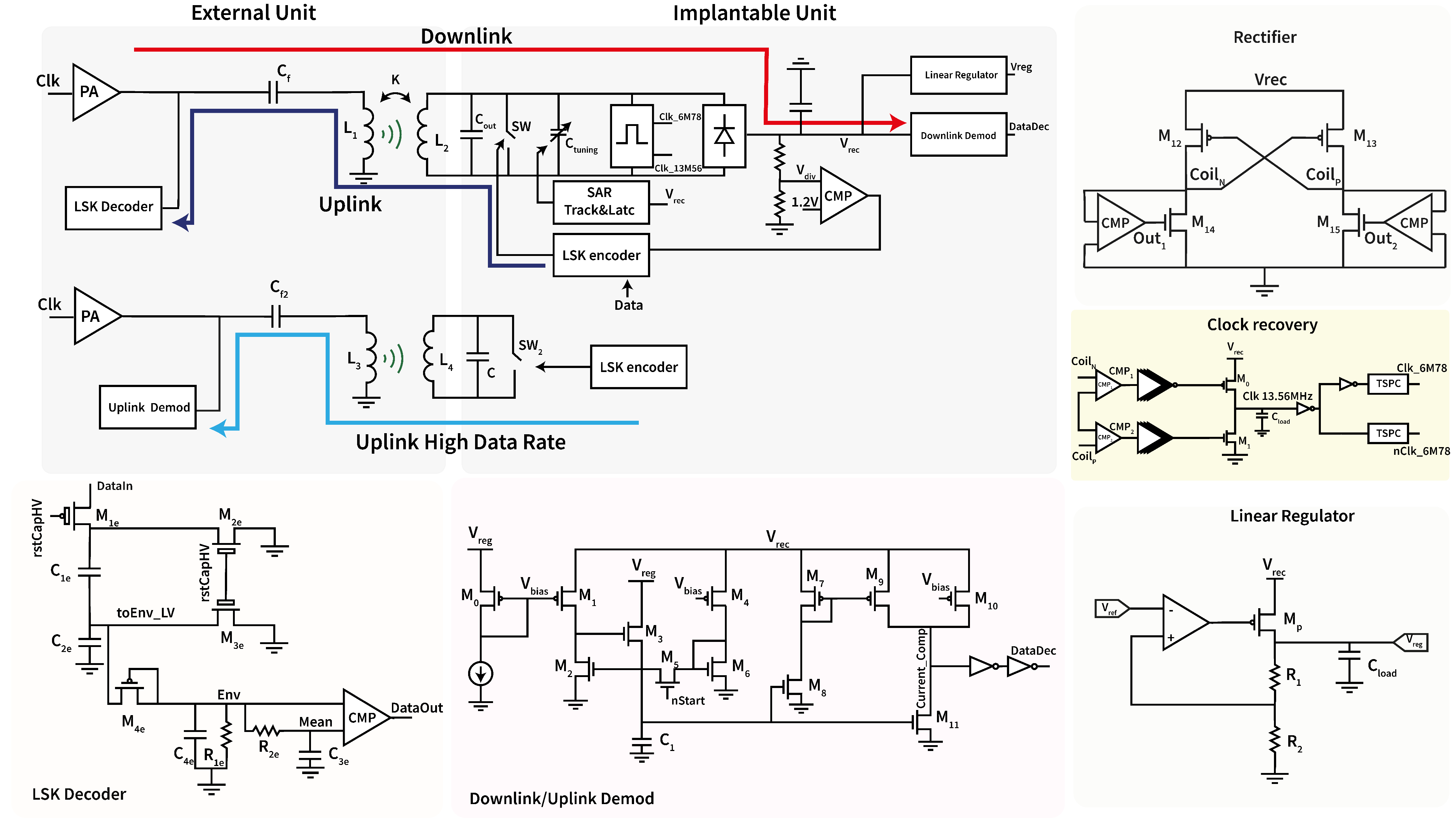
The power line architecture, shown in Figure 2, consists of a rectifier, a track and latch comparator, a linear regulator, and a tunable capacitor, together with digital modules to implement an algorithm required for the automatic tuning mechanism.
The tuning mechanism allows for maximizing the power transmission efficiency, which depends on the coupling between the two resonant LC pairs, to achieve resonance at the carrier frequency. Finite tolerances of the inductive (L) and capacitive (C) elements used to set the resonant frequency, and a slight misalignment of the coupled coils, may reduce the power transmission efficiency of the link. To compensate for such imperfections, the capacitance needed to set the resonance was actually subdivided into two separate capacitors, C o u t and C t u n i n g . C o u t is a fixed-value, discrete, external component soldered directly on the PCB, while C t u n i n g is a programmable device integrated on chip. The tuning algorithm is based on a Successive Approximations approach (SA), which increases or decreases the value of the tuning capacitor, step by step, until the maximum efficiency is obtained. Since the power delivered to the load is proportional to the square of the rectified voltage, which depends on the LC tank capacitor, the tuning algorithm is based on maximizing the rectified voltage to maximize the transmitted power. The tuning capacitor C t u n i n g is realized with several unit capacitors that can be connected in parallel or disconnected with a digital control signal. Starting from a default value, the number of parallel capacitors is increased at each step of the algorithm, and the resulting variation of the rectified voltage is monitored using a track-and-latch comparator. If the voltage increases, the additional parallel capacitor is kept; otherwise, it is disconnected. The digital control module proceeds until all unit parallel capacitors are tested and the optimal value of C t u n i n g is obtained [31,32].
The power supply voltage is obtained by the rectifier shown in Figure 2. This module converts the sine voltage waveform induced on the coil into a DC voltage, making it available as a power supply for the rest of the circuit. The active rectifier is based on two cross-coupled PMOS transistors ( M 12 , M 13 ) and two active diodes formed by two comparator-controlled NMOS transistors ( M 14 , M 15 ). When one of the voltages at the ends of the inductive link varies so that the voltage at either node C o i l N or C o i l P decreases, the voltage on the opposite node ( C o i l P or C o i l N ) increases. Consequently, when the threshold voltage of the PMOS is reached, M 13 or M 12 is turned on and V r e c is shorted to V c o i l P or V c o i l N . The node V r e c is charged simultaneously because when the voltage decreases, one of the comparators (CMP) turns on M 14 or M 15 , thus creating a current path through the inductive link. This results in a decrease in the voltage at the node that previously increased toward positive voltages and an increase in the voltage on the opposite node.
Once the rectified voltage is obtained, a linear regulator is necessary to maintain a stable and reliable output. The implemented circuit, shown in Figure 2, consists of a power transistor (MP) controlled by an error amplifier obtained from an operational transconductance amplifier (OTA) and a voltage reference of 1.2 V generated by a bandgap circuit. The linear regulator adjusts the voltage difference between the rectified voltage and the output ( V r e c V r e g ) through MP, obtaining a fixed output voltage of 2.7 V.

2.1.2. Wireless Data Transfer

The implanted and the external units communicate via two different inductive links. The main link is optimized for power transfer and has a carrier of 13.56 MHz; it is used for low-data-rate, half-duplex, bidirectional communication. The secondary link is optimized for speed and has a 27 MHz carrier; it is used for high-data-rate unidirectional uplink communication from the implantable to the external device.
Data modulation in both uplink channels (low and high bitrate) is based on Load Shift Keying (LSK). A resistive load in the secondary circuit is modified at each bit transmission, causing a detectable change in the primary circuit [33]. The resistive load is switched between open circuit (very high resistance) and short circuit (very low resistance), thanks to a switch implemented with an NMOS high-voltage transistor. Manchester coding is used to represent each bit since it combines the data stream with a clock, making demodulation simpler. Each transmitted symbol requires a full transition of the signal from 0 to 1 and back to 0, ‘0’ and ‘1’ symbols being encoded in the direction of the mid-period transition (rising or falling edge). The serial clock frequency must be twice the data rate. Such a clock is digitally obtained by dividing the 13.56 MHz system clock, which is recovered from the carrier’s frequency (see Figure 2). The encoded data are generated by XORing the data and the serial clock.
The downlink stream on the 13.56 MHz carrier is Manchester-encoded and amplitude-modulated. Demodulation requires detection of the maximum (associated with 1 s) and minimum (associated with 0 s) envelope of the carrier. It is performed by the custom, low-power demodulator shown in Figure 2. As long as the gate of transistor M 5 (driven by digital signal n S t a r t ) is high, the circuit is in idle mode; the bias current of transistor M 0 is mirrored and amplified by transistors M 1 and M 4 , which have the source connected to the rectified voltage V r e c instead of the regulated voltage V r e g . The resulting current I 0 is mirrored back into M 2 , and the sampling capacitor C 1 stores the gate voltage associated with such resting current, which is dependent on the maximum rectified voltage. When signal n S t a r t goes low, demodulation starts; sample capacitor C 1 is isolated and holds the gate voltage associated with I 0 , while transistor M 2 stores the resting current I 0 , which is mirrored by transistors M 8 and M 11 . The current of M 8 is mirrored into M 9 with a gain factor equal to m / n , where m is the multiplicity of M 9 and n the multiplicity of M 7 . Such current is added to the current of M 10 and I 1 and sunk by M 11 . However, current I 1 follows the variations in the rectified voltage V r e c induced by the carrier’s modulation. When the envelope of the carrier reaches its minimum value, I 1 will reach its minimum as well. Transistors M 9 , M 10 , and M 11 , together with the following inverters, act as a current comparator: node C u r r e n t _ C o m p will be high when the current of the PMOS exceeds the current of the NMOS and will be low otherwise. Thus, output voltage D a t a D e c will track the digital value of the transmitted symbol. In particular, writing the equation for the current comparator, D a t a D e c is HIGH if
I M 9 + I M 10 > I M 11
m n I 0 + I 1 > I 0
I 1 I 0 > n m n
where m and n are respectively the multiplicity of transistors M 9 and M 10 , I 0 is the resting current, and I 1 is the modulated current. By properly setting m and n, the comparator will switch between HIGH and LOW as long as the modulated current changes by at least 20 % in either direction. This demodulation mechanism is therefore extremely robust, as it depends only on the percentage variations of the modulating signal. The output bit D a t a D e c is then supplied to the digital logic for decoding. Since communication always starts transmitting a 0, digital decoding is activated upon recognition of the first low–high transition after demodulation starts. A counter will count for a time period T d a t a ± δ in which T d a t a is equal to 1 / f d a t a , i.e., the inverse of the data rate, while δ is a confidence interval chosen to compensate for possible delays. If a logical variation occurs during this period, the bit is evaluated; otherwise, the communication is interrupted and reset.

2.2. External Unit

The external device has two coils required for data communication and power transfer. The coil used for power transfer and low-data-rate communication is a circular coil with 8 turns and an external diameter of 35 mm. The coil for high-data-rate transfer is a figure 8 coil with 7 turns and a 27 mm external diameter. The external unit plays the role of the master in a master–slave communication. All transactions are started by the master, which drives the inductive links to send commands and receive data. It generates the primary 13.56 MHz carrier and the secondary 27 MHz carrier, modulates the primary carrier to send downlink data, and decodes the LSK modulation on both carriers to receive low-data-rate and high-data-rate input streams.
To obtain the two clocks at 13.56 MHz and 27 MHz, a 108.48 MHz external clock is used. The clocks are obtained by appropriately dividing the external reference clock. The derived clocks pass through a non-overlapping buffer to create the clocks and their inverted versions, which are needed to drive a Class-D power amplifier (PA) for data and power transmission. The power stage of the Class-D power amplifier comprises non-overlapping logic, a gate-drive buffer, and two power switches [34]. The typical implementation of a Class-D PA is simple, thus representing a good choice for wireless power transfer [35], even if it is commonly used for audio signal amplification [36,37]. The external unit comprises two Class-D power amplifiers, each serving one of the two inductive links. In the case of the 13.56 MHz clock, optimized for power and not for speed, a high voltage supply of 16 V is used to increase power transfer, thus requiring the use of a level shifter for digital signals and realizing the amplifier with DMOS transistors. The duty cycle of the primary clock is modulated to vary the power amplifier’s transmission efficiency to send data. More specifically, for downlink modulation, the duty cycle of the clock changes from 50% to 25%, causing a reduction in the voltage across the inductor, which modulates the amplitude of the voltage induced on the secondary circuit. Symbol 1 is encoded with the duty cycle 50%, while symbol 0 is obtained with the modulated clock at 25%. The 27 MHz link is optimized for speed and uses a 3.3 V power supply and 3.3 V compatible transistors, but the circuit architecture is the same.
Two different circuits were implemented for demodulation of input data stream: one for low-data-rate communication and one for high-data-rate communication. In the low-data-rate demodulator, the envelope signal is large and a capacitive voltage divider is needed to bring it down to the 0–3.3 V range. Capacitors C 1 e and C 2 e and transistors M 1 e , M 2 e , and M 3 e implement the divider, according to the following Equation (4):
t o E n v L V = C 1 C 1 + C 2 t o E n v H V
where t o E n v L V represents the envelope in the voltage range 3.3 V, while t o E n v H V represents the high-voltage envelope.
The low-pass filter implemented by transistor M 4 e , capacitor C 4 e , and resistor R 1 e extracts the envelope, which is further filtered using the R 2 e - C 3 e filter to obtain the average value. By comparing the envelope and the average, the input bit is decoded. The circuit implemented to demodulate the high-data-rate uplink communication is the same as previously explained for the downlink decoding in the implantable unit.

3. Results

Electromagnetic safety was evaluated through the simulation of the Specific Absorption Rate (SAR). SAR was estimated using Ansys HFSS by simulating the link’s effect on a phantom layer of skin, muscle, and fat. The implantable antenna was positioned between the muscle and the skin layer, while the external antenna was positioned outside the phantom at 1 cm from the implantable pair. The maximum SAR was estimated at 1.43 × 10 4 W/Kg, far below the safety limits. Each circuital block was implemented, laid out, and simulated. The simulations were conducted considering the case in which all front ends are active, with an estimated maximum current demand of 2 mA per front end. To account for this condition, we modeled the system with a load of 10 mA: 8 mA allocated to the four front ends and 2 mA reserved for the implantable communication circuit. This section shows the results and the achieved performances.

3.1. Active Rectifier

The rectifier behavior was simulated by applying a sinusoidal generator at the circuit input. The load was modeled as a 10 mA current generator to represent the absorption of each front end, estimated at 2 mA per FE, and 2 mA for the implantable communication chip.
The efficiency of the active rectifier implemented in the implantable unit was calculated according to the following Equation (5):
η = P L o a d P L o s s + P L o a d
where P L o a d is the power delivered to the circuit, while P L o s s is the power wasted by the rectifier. The load was modeled with a current load of 10 mA, achieving an efficiency of about 95.1 % . The rectifier behavior is shown in Figure 3.

3.2. Linear Regulator

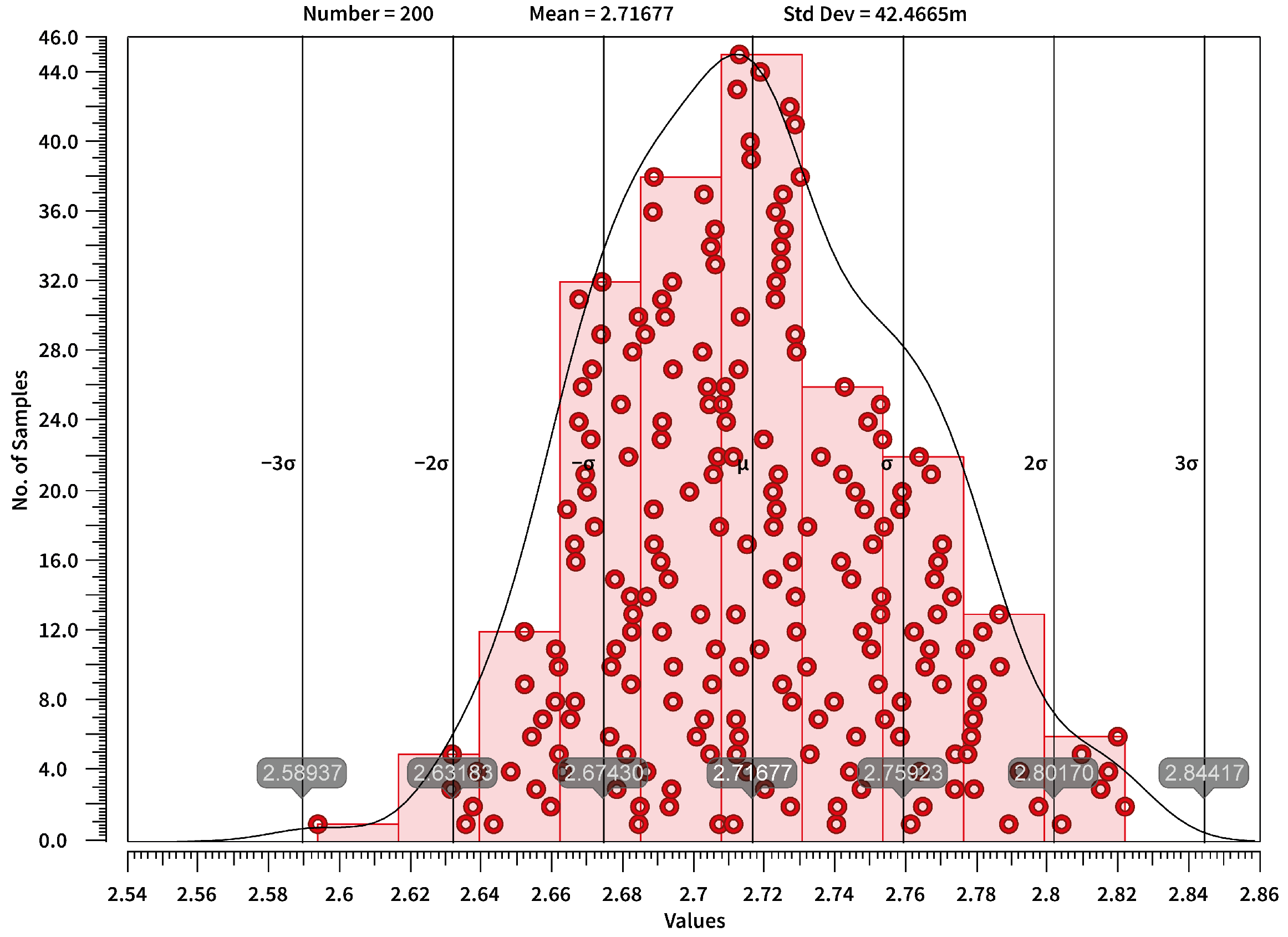
The linear regulator efficiency has been calculated using Equation (5), where P L o s s represents the power consumed by the regulator. The estimated efficiency is 70.5 % . The voltage regulator was tested with a Monte Carlo simulation, obtaining an average value of of 2.71 V and a standard deviation of 42.45 mV, as reported in Figure 4. The low power efficiency achieved is due to the high difference between input and output voltage ( Δ V = 600 mV). Improving efficiency would have required the implementation of a switched converter [38], resulting in higher area consumption and design complexity. Even if the power consumption is relatively low for an implantable application, the simple circuit design of the linear regulator allows for a low encumbrance, which was considered a priority in the proposed application.

3.3. Half-Duplex Link

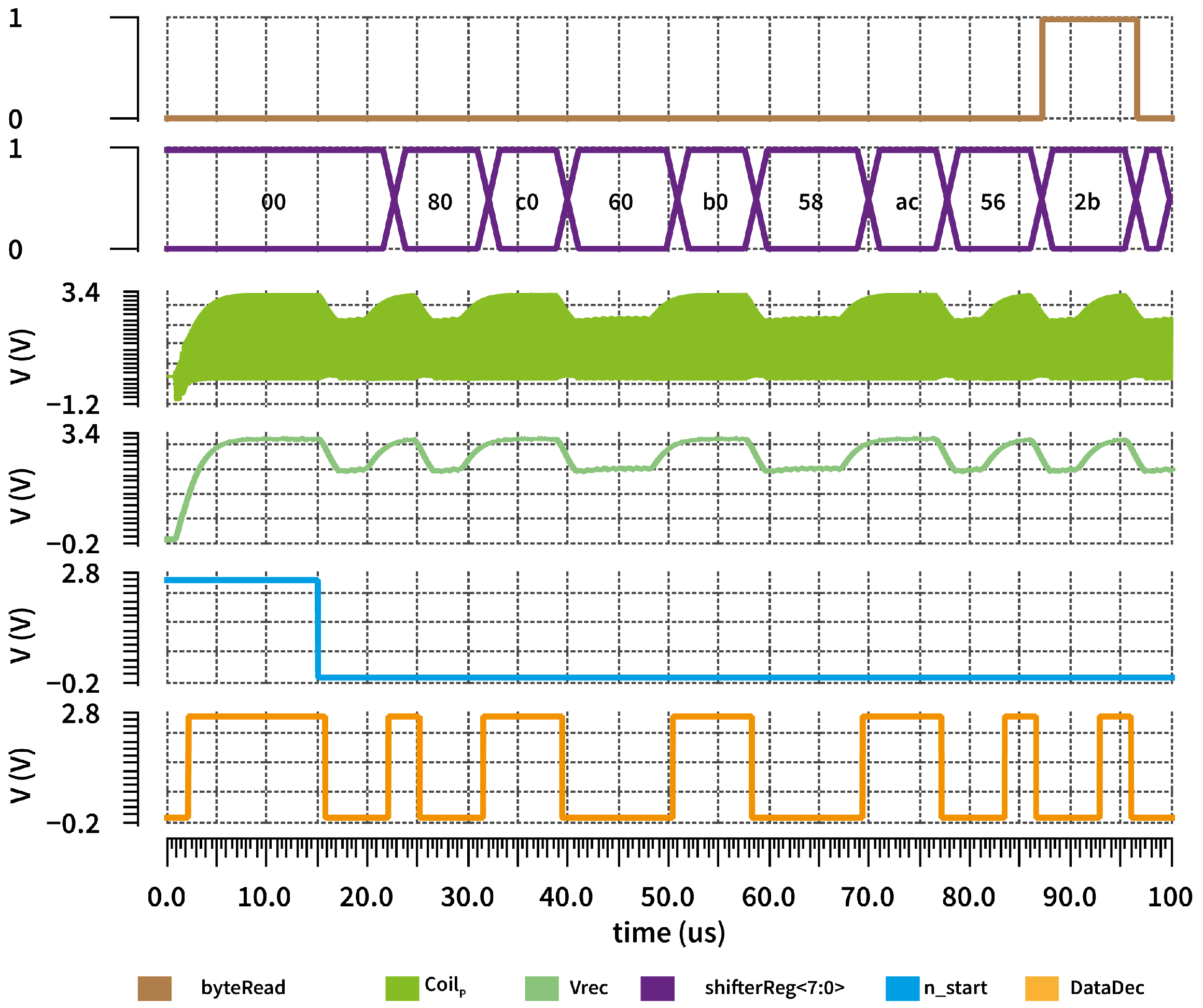
Figure 5 shows the decoded data generated by the demodulation circuit in the implantable unit for the 13.56 MHz inductive link. The voltage across the inductive coil ( C o i l P ) is rectified to extract the envelope ( V r e c ). When n S T A R T goes low, the demodulator is enabled to detect data and initiate data decoding. The extracted data (Z) are then inverted ( D a t a D e c ) and stored in an 8-bit shift register.

3.4. Uplink Low-Data-Rate Demodulation

Figure 6 presents the demodulation of the data transmitted from the implantable unit to the external unit via the low-data-rate channel. In this figure, the voltage ( t o _ e n v ) is brought back to a lower voltage and subsequently filtered two times to obtain the mean and envelope to compare and extract the encoded data. Due to Manchester encoding, the data extracted from the comparator are evaluated and stored in an 8-bit shifter register on the transition from low to high and from high to low.

3.5. Tuning Circuit

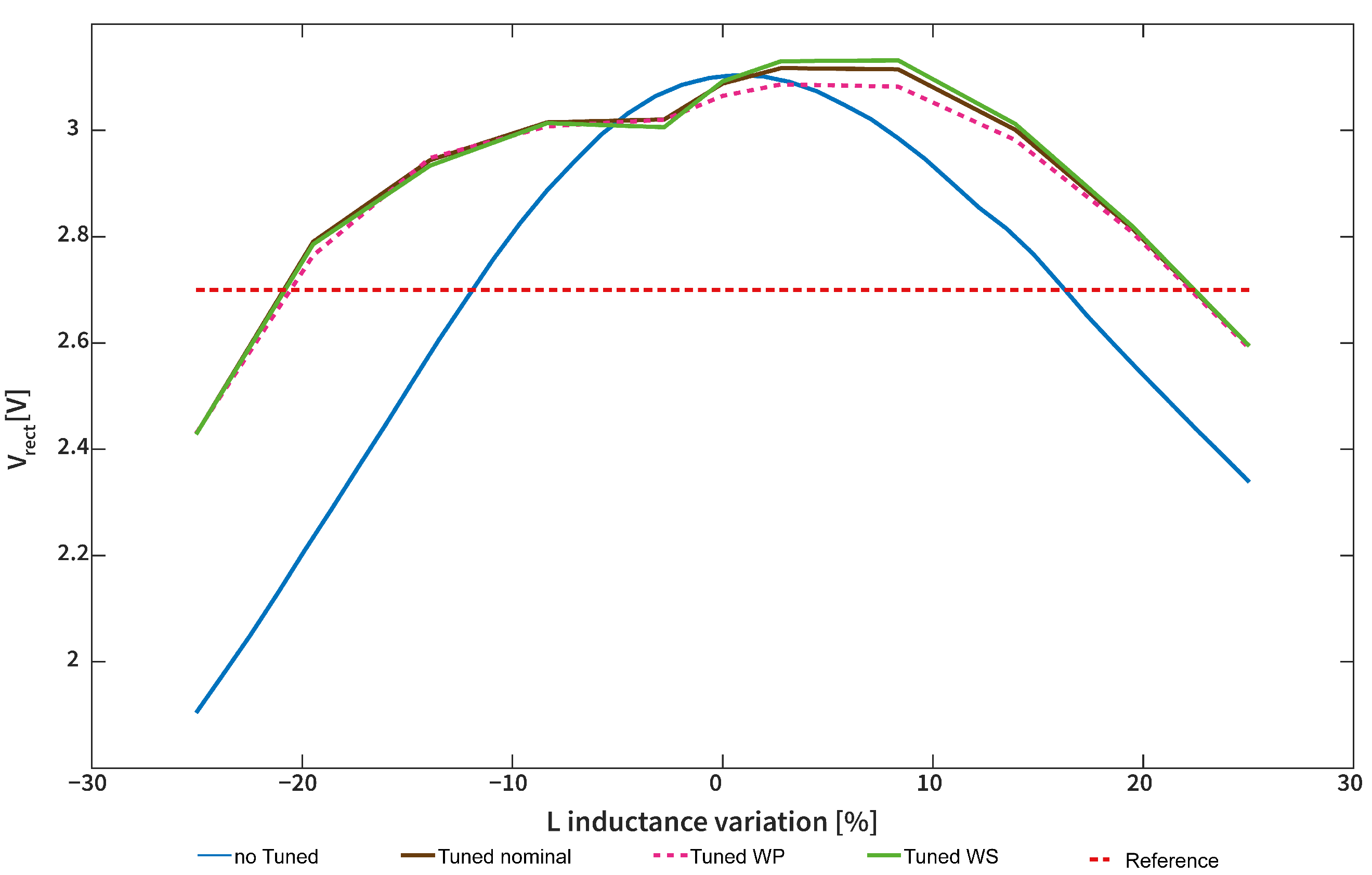
The tuning circuit has been tested using corner analysis, more specifically using the Worst Speed (WS) and Worst Power (WP) corners. As reported in Figure 7, the proposed tuning mechanism can handle variations in the range ±20% of the inductive coil. The algorithm is always completed in less than 100 μ s, making seven complete comparisons [31]. Since the comparator has been implemented using a track-and-latch circuit without any preamplifier, static power consumption can be considered negligible.

3.6. Uplink High-Data-Rate Demodulation

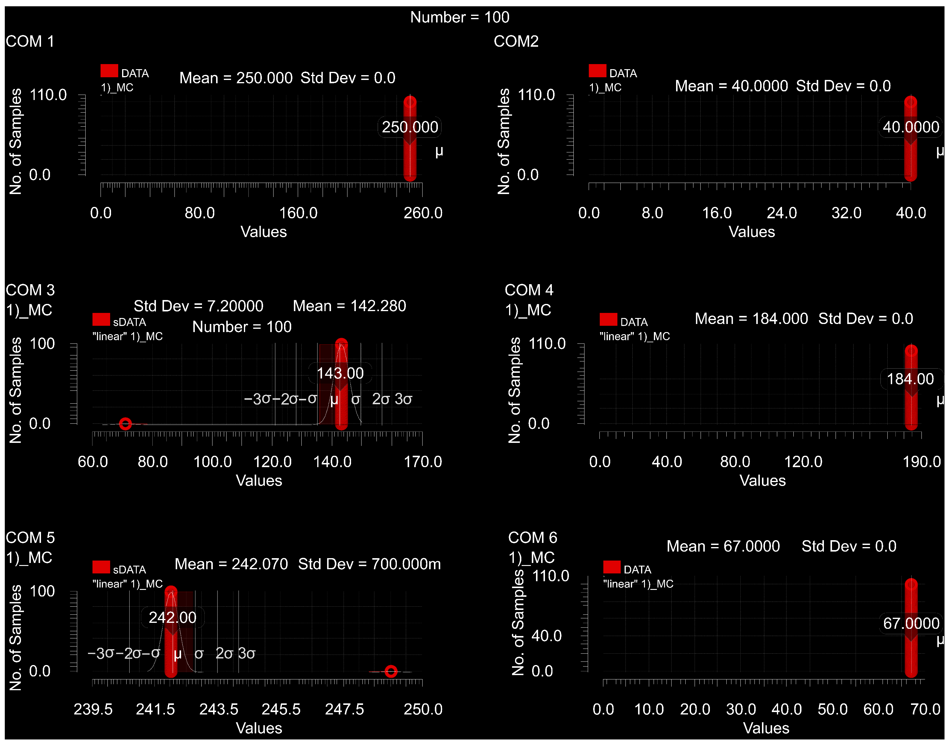
The behavior of the circuit for demodulating data sent from the implantable unit to the external unit through the high-data-rate channel is shown in Figure 8. Data modulation on the implantable unit leads to a variation of voltage on the primary circuit ( t o _ e n v ). The 27 MHz inductive coil ( e n v ) envelope is obtained through a passive filter. Data conversion is triggered when the first 0 is detected. Once conversion starts, data are sampled at time-constant intervals according to the transmission frequency. The decoded data are stored in an 8-bit shifter register and made available to the system when an entire byte has been acquired. To evaluate communication errors, Monte Carlo simulations were performed with process and mismatch variations across 100 samples. The simulations focused on the high-data-rate uplink channel, which is the most critical due to its high transmission speed. The simulation accounted for six consecutive 8-bit word transmissions. The results showed that errors occurred in only 1 of 100 cases, when 6 bits out of 48 failed, as shown in Figure 9.
A data rate of 2.25 Mbps was selected to ensure reliable communication between the external unit and the implantable front ends (FEs). This rate supports up to four FEs, each providing 16 channels of 12-bit data, for a total of 64 channels. The resulting maximum sampling frequency of 2.9 kHz per channel exceeds the bandwidth requirements of EMG and ENG signals. This further enables higher transmission rates for electrode subgroups supporting the use of neuromorphic signal decoding algorithms.

3.7. Layout Design

After simulating all previously presented blocks, the layout has been designed. Figure 10A shows the implantable unit layout with dimensions of 0.99 × 0.2 mm. More than half of the area, more specifically a space of 0.53 × 0.2 mm, is occupied by the capacitors needed for the tuning mechanism, which can be seen on the left side of the layout. An area of 0.12 × 0.08 mm is occupied by the rectifier, whose transistors have been designed using waffle structures to minimize size. A waffle structure has also been implemented to design the power transistor used in the linear regulator, which, together with the bandgap needed to obtain the voltage reference, occupies an area of 0.33 × 0.06 mm. The circuit used for downlink decoding has a dimension of 0.15 × 0.06 mm given mainly by the capacitor, which has been implemented as a parallel of six capacitors to reduce mismatch. The same approach has been used for the capacitors of the power-on-reset circuit, which occupies an area of 0.1 × 0.04 mm. Figure 10B shows the layout of the external device, whose dimensions are 0.7 × 0.17 mm. On the right side, it is possible to see the DMOS transistors used to implement the level shifter and the Class-D power amplifier, which occupy an area of 0.27 × 0.15 mm. In the middle, an area of 0.3 × 0.17 mm is mainly occupied by the capacitors needed to demodulate both high- and low-data-rate uplink channels designed as a parallel of multiple capacitors to reduce mismatch. Lastly, an area of 0.1 × 0.17 mm is needed for the current generator, while the power-on reset circuit has a dimension of 0.02 × 0.08 mm. Although the device has not yet been physically manufactured, we can estimate that, due to the low number of off-chip components, mainly two capacitors, the majority of the implantable device’s size will come from the coils and connectors. However, since the coils are designed to be aligned, their total diameter will only be 22 mm. The overall size of the device is expected to be approximately 39 mm by 30 mm, which aligns with the dimensions of the “Cortex Brain Interchange System” device proposed by CorTec (Freiburg, Germany).
In Table 1, a comparison of the performances of the proposed system is reported.

4. Conclusions

This paper describes the design of an implantable, batteryless power and data hub that can be used within an implantable, distributed hybrid system. The system consists of two devices, one external to the body and one implantable, to control four distinct distributed neural stimulation and recording front ends. The external device generates two distinct wireless carriers for wireless power transmission, therefore eliminating the need for transcutaneous wires for power and data transfer. Communication between implantable and external units is of the master–slave type and occurs via two distinct wireless channels. A channel with a 13.56 MHz carrier is used for power transfer and bidirectional half-duplex communication between the external and implantable devices to send commands and monitor the implanted system. The second communication channel is used for high-data-rate transmission from the implantable device to the outside world, ensuring the transmission of data collected by the connectable implantable sensing peripherals. The modularity of the system, which can be connected to up to four different front ends distributed along the body and not strictly near the central implantable unit, will enhance the development of neural prosthetic systems and continuous monitoring bioelectronic systems, allowing for the simultaneous monitoring and stimulation of different nerves and organs with the same device. The system described has been tested through rigorous simulations, such as Monte Carlo and corner analysis. However, it still needs to be evaluated in the laboratory using benchtop instruments, then subjected to in vivo tests in animals, and finally verified in human volunteers.

Author Contributions

Conceptualization, R.C. and M.B.; methodology, R.C.; validation, R.C. and C.S.; resources, M.B.; data curation, R.C. and E.F.; writing—original draft preparation, R.C.; writing—review and editing, R.C., C.S., E.F., and M.B.; visualization, R.C.; supervision, M.B.; project administration, M.B.; funding acquisition, M.B. All authors have read and agreed to the published version of the manuscript.

Funding

This research received no external funding.

Informed Consent Statement

Not applicable.

Acknowledgments

This paper was produced while attending the PhD programme in Electronic and Computer Engineering at the University of Cagliari, Cycle XXXVIII, with the support of a scholarship financed by the Ministerial Decree no. 352 of 9th April 2022, based on the NRRP - funded by the European Union - NextGenerationEU - Mission 4 "Education and Research", Component 1 "Enhancement of the offer of educational services: from nurseries to universities” - Investment 3.4 “Advanced teaching and university skills”.

Conflicts of Interest

The authors declare no conflicts of interest.

References

  1. Joung, Y.H. Development of implantable medical devices: From an engineering perspective. Int. Neurourol. J. 2013, 17, 98–106. [Google Scholar] [CrossRef]
  2. Sobot, R. Implantable Technology: History, Controversies, and Social Implications [Commentary]. IEEE Technol. Soc. Mag. 2018, 37, 35–45. [Google Scholar] [CrossRef]
  3. Xu, S.; Liu, Y.; Lee, H.; Li, W. Neural interfaces: Bridging the brain to the world beyond healthcare. Exploration 2024, 4, 20230146. [Google Scholar] [CrossRef] [PubMed]
  4. Yoo, S.; Lee, J.; Joo, H.; Sunwoo, S.H.; Kim, S.; Kim, D.H. Wireless Power Transfer and Telemetry for Implantable Bioelectronics. Adv. Healthc. Mater. 2021, 10, 2100614. [Google Scholar] [CrossRef] [PubMed]
  5. Ortiz-Catalan, M. Ultrasound-powered tiny neural stimulators. Nat. Biomed. Eng. 2020, 4, 144–145. [Google Scholar] [CrossRef]
  6. Ortiz-Catalan, M.; Mastinu, E.; Sassu, P.; Aszmann, O.; Brånemark, R. Self-Contained Neuromusculoskeletal Arm Prostheses. N. Engl. J. Med. 2020, 382, 1732–1738. [Google Scholar] [CrossRef]
  7. Zhou, Y.; Liu, C.; Huang, Y. Wireless power transfer for implanted medical application: A review. Energies 2020, 13, 2837. [Google Scholar] [CrossRef]
  8. Lorach, H.; Galvez, A.; Spagnolo, V.; Martel, F.; Karakas, S.; Intering, N.; Vat, M.; Faivre, O.; Harte, C.; Komi, S.; et al. Walking naturally after spinal cord injury using a brain–spine interface. Nature 2023, 618, 126–133. [Google Scholar] [CrossRef]
  9. Kindermann, M.; Schwaab, B.; Berg, M.; Fröhlig, G. Longevity of dual chamber pacemakers: Device and patient related determinants. Pacing Clin. Electrophysiol. 2001, 24, 810–815. [Google Scholar] [CrossRef]
  10. Zhang, J.; Das, R.; Zhao, J.; Mirzai, N.; Mercer, J.; Heidari, H. Battery-Free and Wireless Technologies for Cardiovascular Implantable Medical Devices. Adv. Mater. Technol. 2022, 7, 2101086. [Google Scholar] [CrossRef]
  11. McGlynn, E.; Nabaei, V.; Ren, E.; Galeote-Checa, G.; Das, R.; Curia, G.; Heidari, H. The Future of Neuroscience: Flexible and Wireless Implantable Neural Electronics. Adv. Sci. 2021, 8, 2002693. [Google Scholar] [CrossRef]
  12. Singer, A.; Robinson, J.T. Wireless Power Delivery Techniques for Miniature Implantable Bioelectronics. Adv. Healthc. Mater. 2021, 10, 2100664. [Google Scholar] [CrossRef] [PubMed]
  13. Khan, S.R.; Pavuluri, S.K.; Cummins, G.; Desmulliez, M.P.Y. Wireless power transfer techniques for implantable medical devices: A review. Sensors 2020, 20, 3487. [Google Scholar] [CrossRef] [PubMed]
  14. Agarwal, K.; Jegadeesan, R.; Guo, Y.X.; Thakor, N.V. Wireless Power Transfer Strategies for Implantable Bioelectronics. IEEE Rev. Biomed. Eng. 2017, 10, 136–161. [Google Scholar] [CrossRef] [PubMed]
  15. Won, S.M.; Cai, L.; Gutruf, P.; Rogers, J.A. Wireless and battery-free technologies for neuroengineering. Nat. Biomed. Eng. 2023, 7, 405–423. [Google Scholar] [CrossRef]
  16. Kim, A.; Ochoa, M.; Rahimi, R.; Ziaie, B. New and Emerging Energy Sources for Implantable Wireless Microdevices. IEEE Access 2015, 3, 89–98. [Google Scholar] [CrossRef]
  17. Wirdatmadja, S.A.; Balasubramaniam, S.; Koucheryavy, Y.; Jornet, J.M. Wireless optogenetic neural dust for deep brain stimulation. In Proceedings of the 2016 IEEE 18th International Conference on e-Health Networking, Applications and Services (Healthcom 2016), Munich, Germany, 14–17 September 2016. [Google Scholar] [CrossRef]
  18. Neely, R.M.; Piech, D.K.; Santacruz, S.R.; Maharbiz, M.M.; Carmena, J.M. Recent advances in neural dust: Towards a neural interface platform. Curr. Opin. Neurobiol. 2018, 50, 64–71. [Google Scholar] [CrossRef]
  19. Seo, D.; Carmena, J.M.; Rabaey, J.M.; Alon, E.; Maharbiz, M.M. Neural Dust: An Ultrasonic, Low Power Solution for Chronic Brain-Machine Interfaces. arXiv 2013, arXiv:1307.2196. [Google Scholar] [CrossRef]
  20. Tyler, D.J. Neural interfaces for somatosensory feedback: Bringing life to a prosthesis. Curr. Opin. Neurol. 2015, 28, 574–581. [Google Scholar] [CrossRef]
  21. Johnson, B.C.; Shen, K.; Piech, D.; Ghanbari, M.M.; Li, K.Y.; Neely, R.; Carmena, J.M.; Maharbiz, M.M.; Muller, R. StimDust: A 6.5mm3, Wireless Ultrasonic Peripheral Nerve Stimulator with 82% Peak Chip Efficiency. In Proceedings of the 2018 IEEE Custom Integrated Circuits Conference (CICC), San Diego, CA, USA, 8–11 April 2018; pp. 1–4. [Google Scholar] [CrossRef]
  22. Piech, D.; Johnson, B.C.; Shen, K.; Ghanbari, M.M.; Li, K.Y.; Neely, R.M.; Muller, R. A wireless millimetre-scale implantable neural stimulator with ultrasonically powered bidirectional communication. Nat. Biomed. Eng. 2020, 4, 207–222. [Google Scholar] [CrossRef]
  23. Montgomery, K.L.; Yeh, A.J.; Ho, J.S.; Tsao, V.; Mohan Iyer, S.; Grosenick, L.; Ferenczi, E.A.; Tanabe, Y.; Deisseroth, K.; Poon, A.S.Y.; et al. Wirelessly powered, fully internal optogenetics for brain, spinal and peripheral circuits in mice. Nat. Methods 2015, 12, 969–974. [Google Scholar] [CrossRef]
  24. Park, S.I.; Shin, G.; Banks, A.; McCall, J.G.; Siuda, E.R.; Schmidt, M.J.; Chung, H.U.; Noh, K.N.; Mun, J.G.; Rhodes, J.; et al. Ultraminiaturized photovoltaic and radio frequency powered optoelectronic systems for wireless optogenetics. J. Neural. Eng. 2015, 12, 056002. [Google Scholar] [CrossRef]
  25. Marincic, A.S.; Grade, B.; Avi, Y. Nikola tesla and the wireless transmission of energy. IEEE Trans. Power Appar. Syst. 1982, 101, 4064–4068. [Google Scholar] [CrossRef]
  26. Patrick, J.F.; Busby, P.A.; Gibson, P.J. The Development of the Nucleus®FreedomTM Cochlear Implant System. Trends Amplif. 2006, 10, 175–200. [Google Scholar] [CrossRef]
  27. Zeng, F.G.; Rebscher, S.; Harrison, W.; Sun, X.; Feng, H. Cochlear Implants: System Design, Integration, and Evaluation. IEEE Rev. Biomed. Eng. 2008, 1, 115–142. [Google Scholar] [CrossRef] [PubMed]
  28. Habibagahi, I.; Omidbeigi, M.; Hadaya, J.; Lyu, H.; Jang, J.; Ardell, J.L.; Bari, A.A.; Babakhani, A. Vagus nerve stimulation using a miniaturized wirelessly powered stimulator in pigs. Sci. Rep. 2022, 12, 8184. [Google Scholar] [CrossRef] [PubMed]
  29. Lyu, H.; John, M.; Burkland, D.; Greet, B.; Post, A.; Babakhani, A.; Razavi, M. Synchronized Biventricular Heart Pacing in a Closed-chest Porcine Model based on Wirelessly Powered Leadless Pacemakers. Sci. Rep. 2020, 10, 2067. [Google Scholar] [CrossRef]
  30. Salis, C.; Collu, R.; Barbaro, M. Demodulation Circuit for Power and Bidirectional Data Transmission in Implantable Distributed Wired System. In Proceedings of the 2024 19th Conference On Ph.D Research In Microelectronics And Electronics (PRIME), Larnaca, Cyprus, 9–12 June 2024; pp. 1–4. [Google Scholar]
  31. Collu, R.; Salis, C.; Barbaro, M. An Automatic Tuning System to Improve Near-Field Powering in Implanted Electronics. In Proceedings of the PRIME 2022—17th International Conference on Ph.D Research in Microelectronics and Electronics, Villasimius, Italy, 12–15 June 2022. [Google Scholar] [CrossRef]
  32. Gosselin, P.; Puddu, R.; Carreira, A.; Ghanad, M.; Barbaro, M.; Dehollain, C. A CMOS automatic tuning system to maximize remote powering efficiency. In Proceedings of the IEEE 2017 IEEE International Symposium on Circuits and Systems (ISCAS), Baltimore, MD, USA, 28–31 May 2017. [Google Scholar]
  33. Tang, Z.; Smith, B.; Schild, J.H.; Peckham, P.H. Data Transmission from an Implantable Biotelemeter by Load-Shift Keying Using Circuit Configuration Modulator. IEEE Trans. Biomed. Eng. 1995, 42, 524–528. [Google Scholar] [CrossRef]
  34. Baxandall, P.J. Transistor Sine-Wave LC oscillators. Some General Considerations and New Developments. Proc. IEE Part B Electron. Commun. Eng. 1960, 106, 748–758. [Google Scholar] [CrossRef]
  35. Berkhout, M. An integrated 200-W class-D audio amplifier. IEEE J. Solid-State Circuits 2003, 38, 1198–1206. [Google Scholar] [CrossRef]
  36. Mei, S.; Hu, Y.; Xu, H.; Wen, H. The Class D Audio Power Amplifier: A Review. Electronics 2022, 11, 3244. [Google Scholar] [CrossRef]
  37. Shi, L.; Rodriguez, J.C.; Carrizosa, M.J.; Alou, P. ZVS tank optimization for class-D amplifiers in high frequency WPT applications. In Proceedings of the IEEE Applied Power Electronics Conference and Exposition (APEC), Phoenix, AZ, USA, 14–17 June 2021; pp. 1593–1598. [Google Scholar] [CrossRef]
  38. Park, W.; Namgoong, G.; Choi, E.; Bien, F. An On-/Off-Time Sensing-Based Load-Adaptive Mode Control of Triple Mode Buck Converter for Implantable Medical Devices. IEEE Trans. Biomed. Circuits Syst. 2023, 17, 585–597. [Google Scholar] [CrossRef]
  39. Lee, B.; Kiani, M.; Ghovanloo, M. A Triple-Loop Inductive Power Transmission System for Biomedical Applications. IEEE Trans. Biomed. Circuits Syst. 2016, 10, 138–148. [Google Scholar] [CrossRef]
  40. Karimi, M.J.; Jin, M.; Zhou, Y.; Dehollain, C.; Schmid, A. Wirelessly Powered and Bi-directional Data Communication System with Adaptive Conversion Chain for Multisite Biomedical Implants Over Single Inductive Link. IEEE Trans. Biomed. Circuits Syst. 2024, 18, 636–647. [Google Scholar] [CrossRef]
  41. Wang, S.H.; Huang, Y.K.; Chen, C.Y.; Tang, L.Y.; Tu, Y.F.; Chang, P.C.; Lee, C.F.; Yang, C.H.; Hung, C.C.; Liu, C.H.; et al. Design of a Bone-Guided Cochlear Implant Microsystem With Monopolar Biphasic Multiple Stimulations and Evoked Compound Action Potential Acquisition and Its In Vivo Verification. IEEE J. Solid-State Circuits 2021, 56, 3062–3076. [Google Scholar] [CrossRef]
Figure 1. Representation of the proposed bidirectional communication system, which consists of two main parts: an external unit and an implantable unit. The external unit will be mounted on a PCB and equipped with two inductive links for power transmission and communication with the implantable device, which will be surgically placed in a body site such as the chest. The implantable unit connects to neural front ends in the body via medical cables to acquire biopotentials and stimulate peripheral nerves.
Jsan 14 00092 g001
Figure 2. Proposed architecture of the external and implantable units. The external circuit is used to generate the wireless carrier, transmit power, and demodulate the data given by the implantable unit. The implantable unit has to convert power via a rectifier and linear regulator and communicate with the external unit.
Jsan 14 00092 g002
Figure 3. Active rectifier output. The current flow that charges node Vrec is generated by the comparators C M P 1 and C M P 2 , which activate respectively when the voltages C o i l P or C o i l N reach their maximum values. This leads to obtaining the envelope of the input voltage.
Jsan 14 00092 g003
Figure 4. Monte Carlo results obtained by conducting the simulation on 100 samples.
Jsan 14 00092 g004
Figure 5. Decoded data obtained from the rectified voltage used in the current demodulator. The signal b y t e R e a d goes high when 8 bits have been acquired.
Jsan 14 00092 g005
Figure 6. Uplink demodulation of the low-data-rate channel. The decoded data are saved in a shifter register, and a data read signal goes high after acquiring 8 bits.
Jsan 14 00092 g006
Figure 7. Rectified voltage optimization due to tuning. The value of the receiver coil inductance has been changed between −25% and 25%. The tuning mechanism allowed for compensation of variations in the range of ±20% of the nominal power coil inductance.
Jsan 14 00092 g007
Figure 8. Uplink demodulation of the high-data-rate channel. Data modulation (data) in the implantable unit involves varying its active load and the reflected load in the external unit (to_env). The voltage is then rectified (env) and used for the demodulation (out). The signal byteRead goes high after acquiring 8 bits previously stored in a shifter register.
Jsan 14 00092 g008
Figure 9. Uplink demodulation has been deeply tested via Monte Carlo analysis across 100 samples. Simulations have been performed to verify the robustness of communication during the transmission of several bytes. Errors were found in only one seed.
Jsan 14 00092 g009
Figure 10. Proposed layout of (A) implantable unit and (B) external unit.
Jsan 14 00092 g010
Table 1. Performance comparison of the proposed system.
WorkWPT Carrier (MHz)Downlink Data RateUplink Data RateAC/DC Conv. Eff.Coil Config (No. Coil)Tech.
 [39]13.5650 kbps160 bps76.2 %30.35 μ m
 [40]13.56–6.78100 kbps678 kbps80.1 %20.18 μ m
 [41]13.56339 kbps340 kbps90.1 %20.18 μ m
30 kbps (@13.56 MHz)
This work13.56106 kbps 95.1 %40.18 μ m
2.25 Mbps (@27 MHz)
Disclaimer/Publisher’s Note: The statements, opinions and data contained in all publications are solely those of the individual author(s) and contributor(s) and not of MDPI and/or the editor(s). MDPI and/or the editor(s) disclaim responsibility for any injury to people or property resulting from any ideas, methods, instructions or products referred to in the content.