
Dual-Purpose Star Tracker and Space Debris Detector: Miniature Instrument for Small Satellites

 , ,
, ,  ,
,  and
and 
Abstract
1. Introduction
2. Previous Research
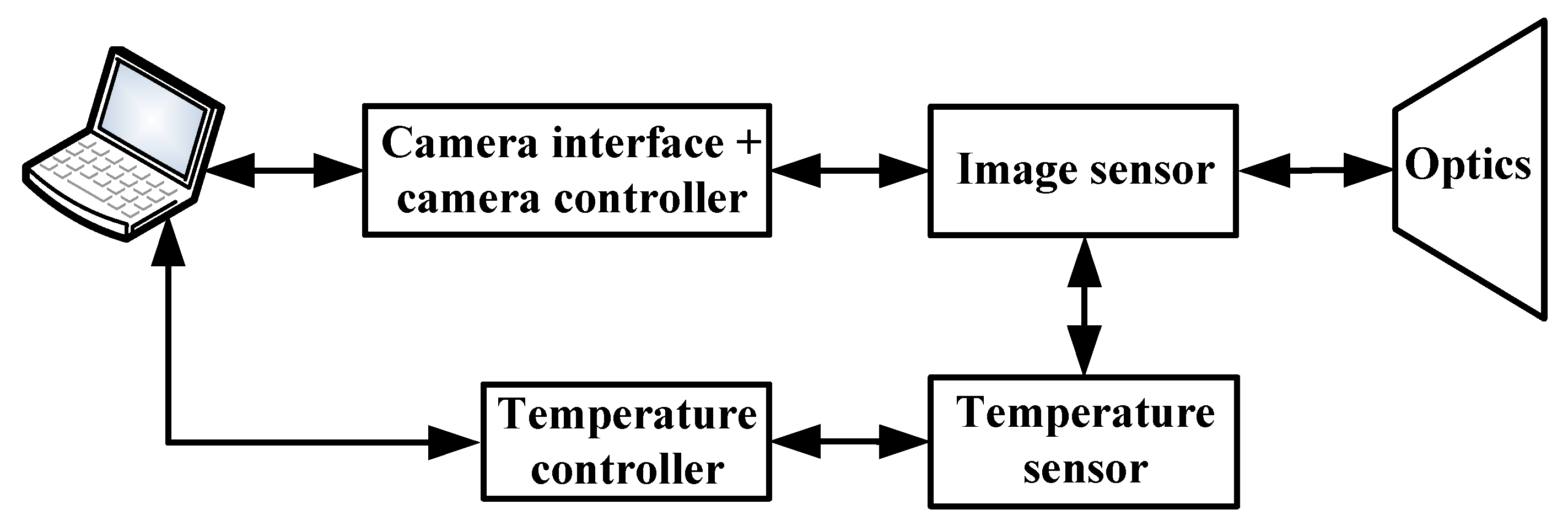
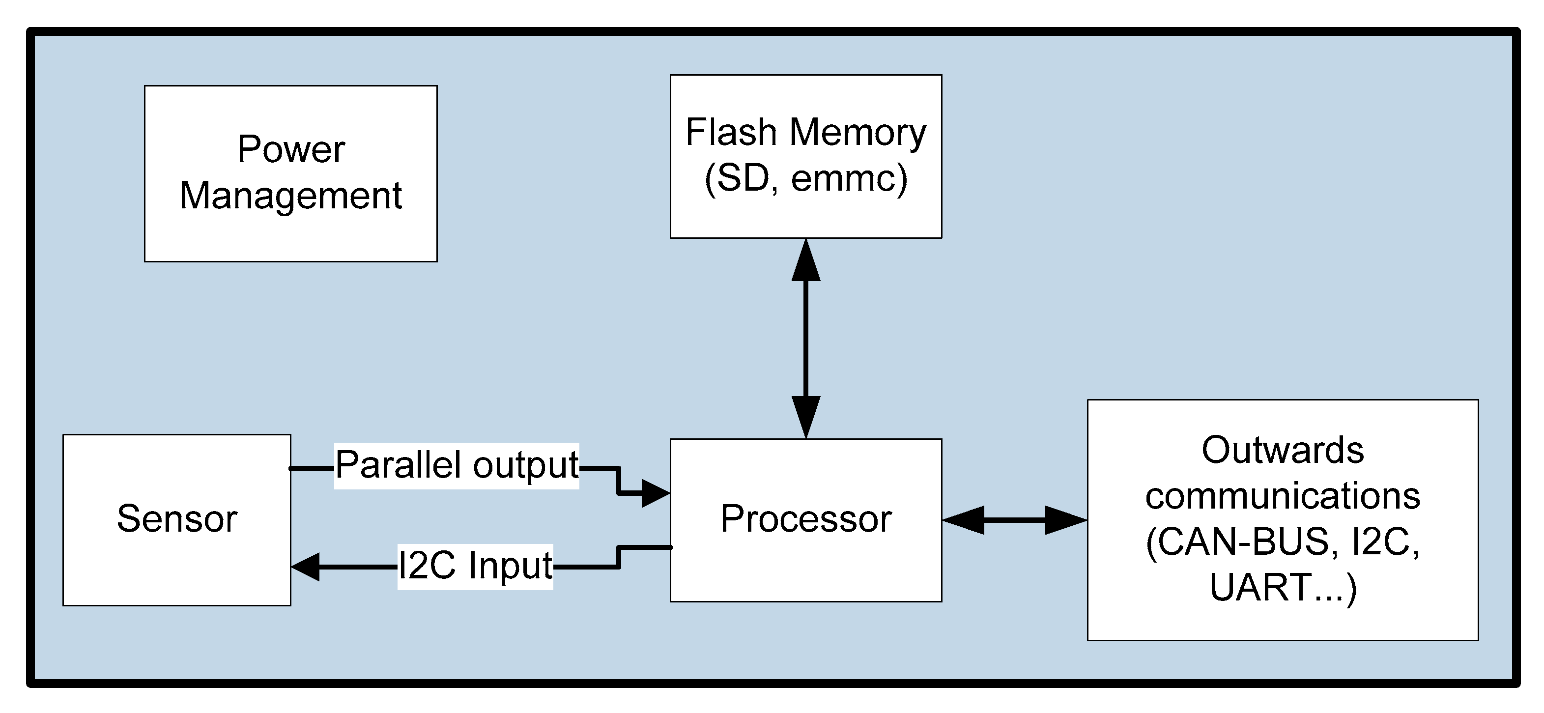
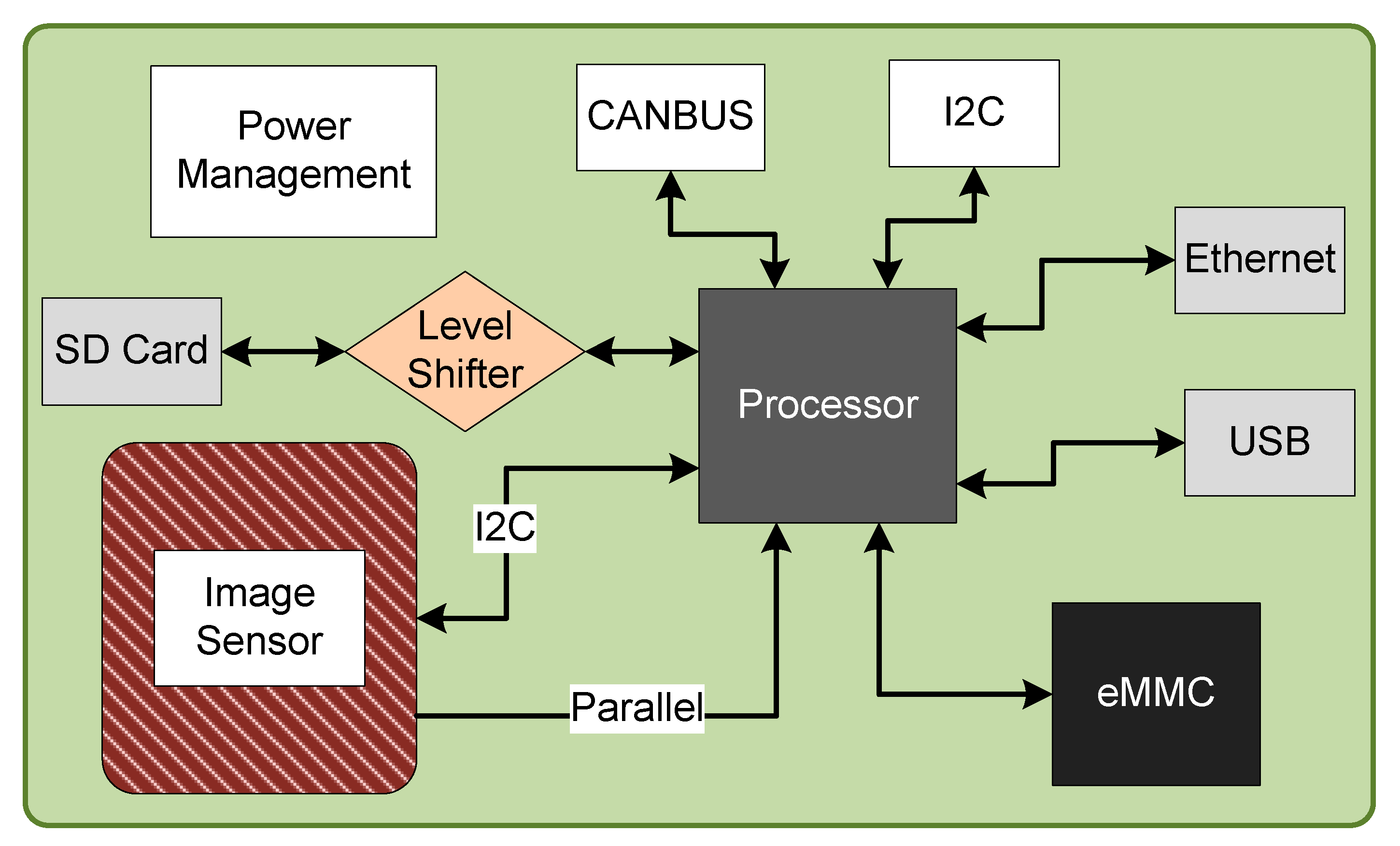
3. Optical Imaging System Conception and Design
- (1)
- Power management block: responsible for switching and controlling the power draw of the system;
- (2)
- Flash memory block: the primary memory storage for the system; it can be a Secure Digital (SD) card or an embedded MultiMediaCard (eMMC) chip;
- (3)
- Sensor block: composed of the CMOS sensor, the power supply management of the sensor and parallel and series communication interfaces;
- (4)
- Processor block: composed of the central processing unit (CPU) and the auxiliary components required to run the algorithms and perform image processing;
- (5)
- Outwards communications block: set for different protocols and interfaces to communicate with the onboard computer system (OBCS) of the system via CAN-BUS, I2C and Ethernet.
3.1. Image Sensor
- A CMOS is preferable to a Charge-Coupled Device (CCD).
- The pixel size should be between 2 µm and 6 µm, with the optimal pixel size being in the 4 µm to 6 µm range. A larger pixel size increases the sensor’s sensitivity.
- A higher resolution increases accuracy but requires larger power consumption, memory and computational capacity. Moreover, it can induce the identification of false alarms by the algorithm. The minimal desired resolution is 512 pixels × 512 pixels.
- The image sensor must have a minimal SNR between 5 to 8.
- The image sensor should have a maximum power consumption of 500 mW.
- The image sensor must be capable of operating in the harsh environment of space. Thus, the sensor must mainly resist space radiation and must operate across a wide range of temperatures.
3.2. Processor
4. STR Breadboard Layout Design
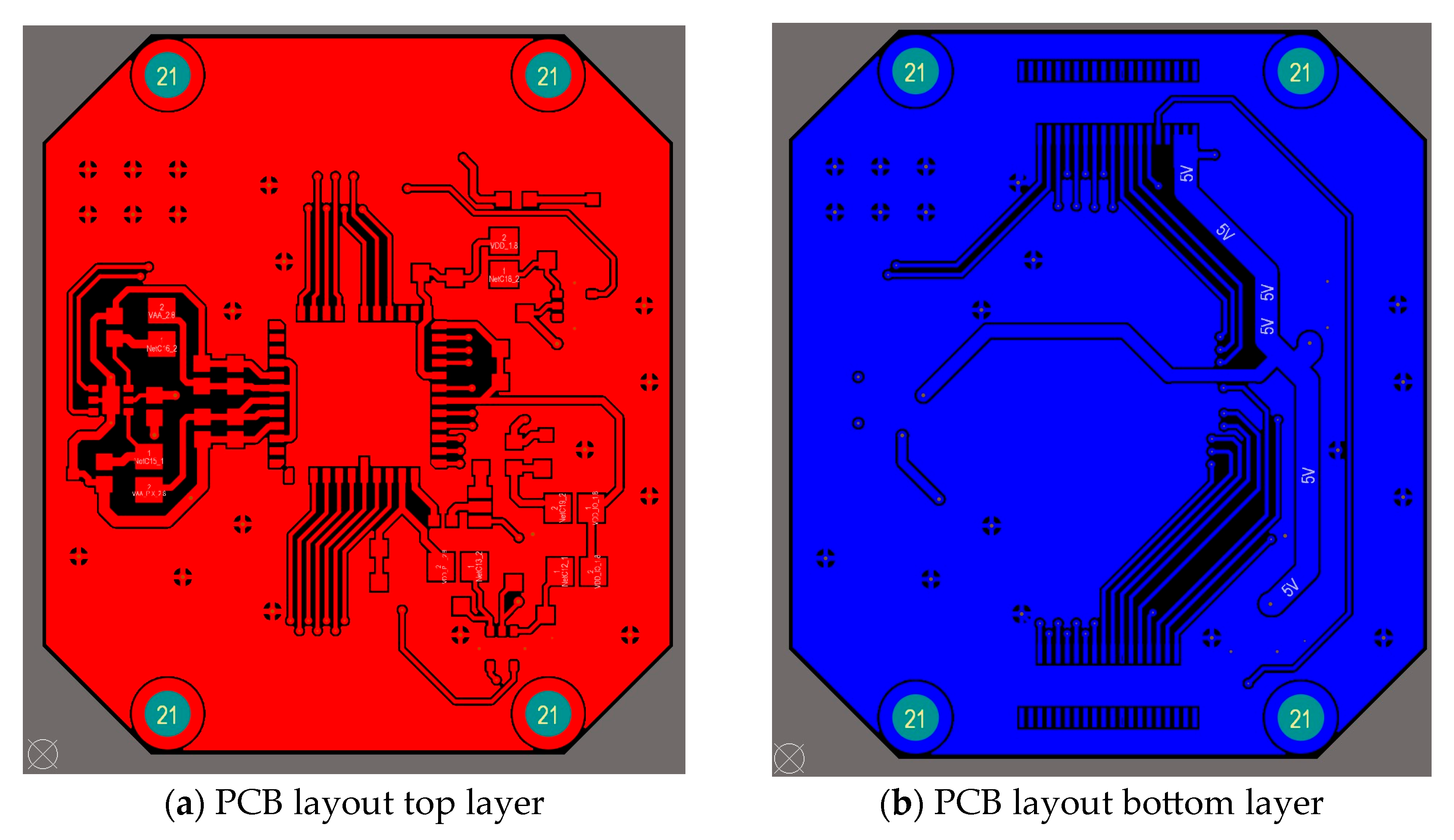
4.1. Image Sensor Breadboard Layout
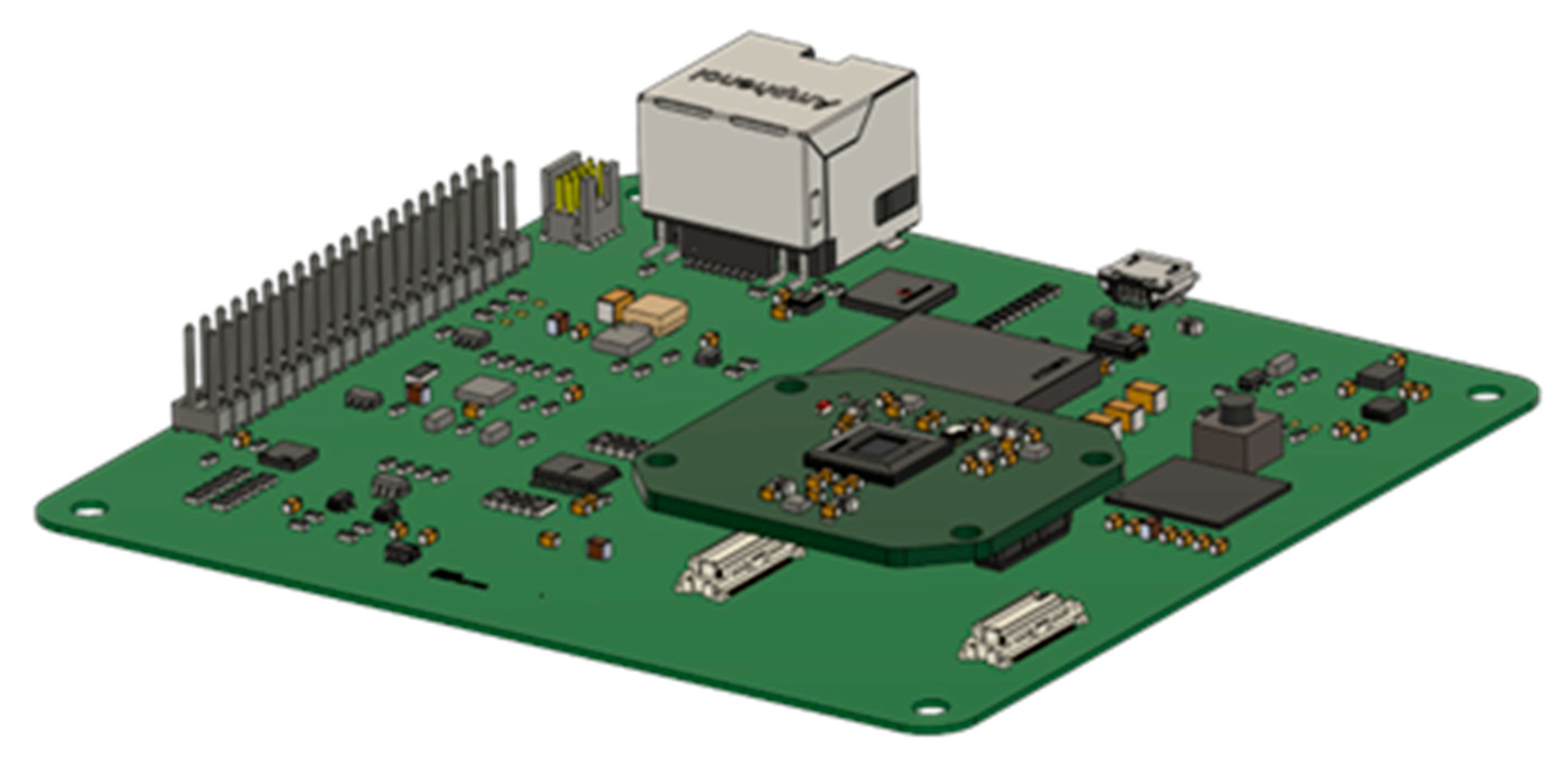
4.2. Processor Breadboard Layout
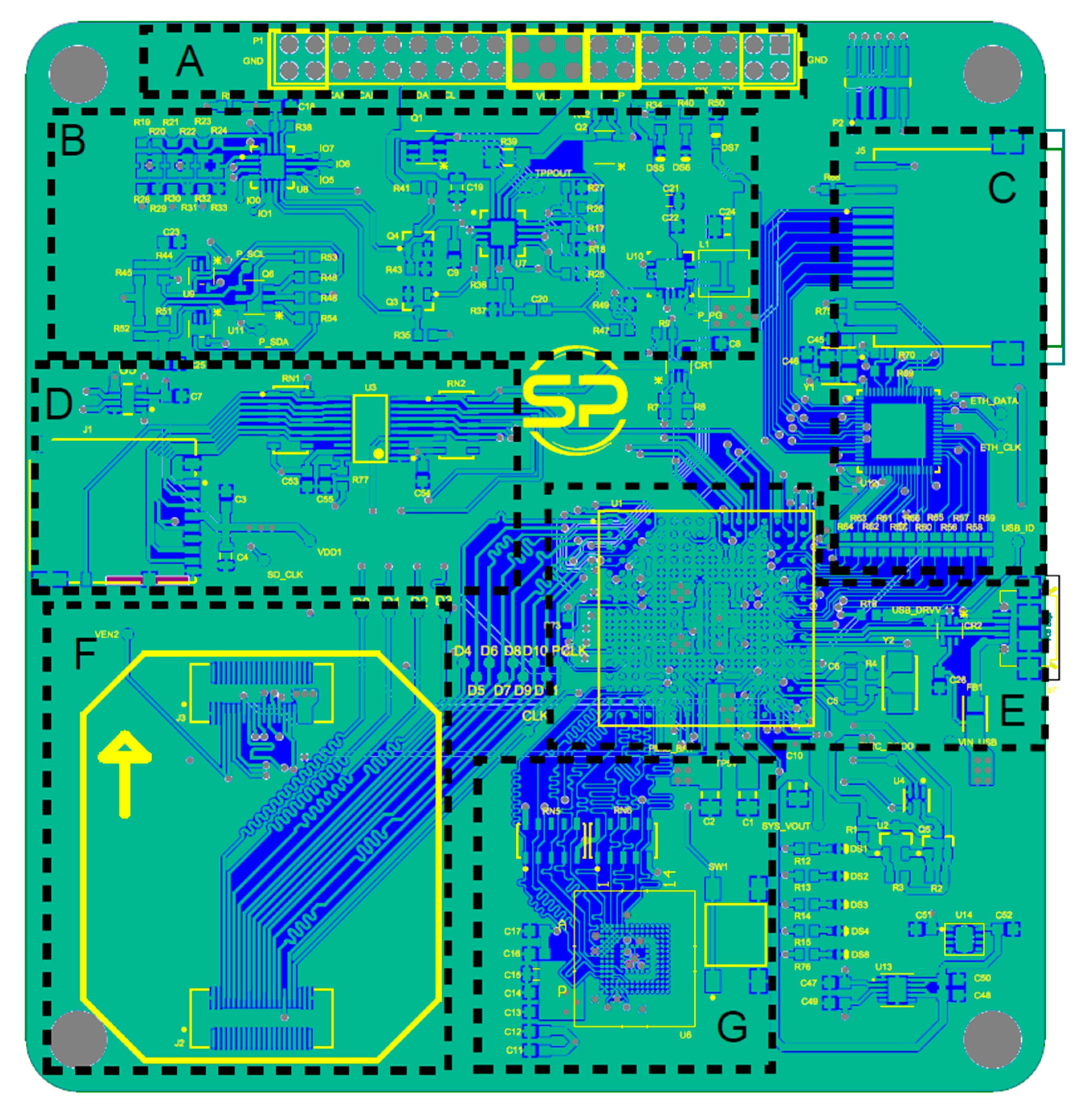
- A: This is a connector located in the top section of the PCB and acts as the primary power input interface, granting access to communication buses such as I2C, CAN Bus and UART for external peripherals.
- B: The PMU regulates power throughout the board. It features a switching voltage regulator that converts input voltages ranging from +5 V to +15 V down to a stable +5 V, along with two additional voltage regulators providing +5 V (primary) and +1.8 V (secondary) outputs. A 1 A current limiter is included for protection, and a timer circuit resets the power in the event of failure, thereby enhancing system reliability.
- C: An Ethernet driver and port to facilitate network communication, enable high-speed data transfers and allow for package updates for the STR.
- D: A micro SD card slot offers a memory expansion option and provides a convenient means for system debugging. By swapping different SD cards, users can test configurations and analyze data on a computer, streamlining the troubleshooting process.
- E: The core of the PCB contains the microprocessor and a USB connector, which is utilized for system debugging purposes.
- F: The bottom-left section features a dedicated connector for interfacing with the STR board, ensuring seamless integration between both systems.
- G: An eMMC storage module serves as a secondary memory option. After debugging, testing and configuring are completed, the eMMC is designed to be flashed with the same operating system as the SD card and to take its place in operation.
5. STR Implementation
6. STR Tests and Results
6.1. Image Sensor Tests
6.2. Power Consumption and Thermal Analysis
- (a)
- The star tracker at a Sun exclusion angle of 18.5°;
- (b)
- The star tracker pointing directly at the Sun;
- (c)
- The star tracker operating in shadow, a cold case with all electronic components (EEEs) turned off.
- (a)
- Boot mode: During this mode the OS is loaded to the CPU, installing every device tree and kernel module.
- (b)
- Idle mode: In this mode, the processor is ON but no program is running. This is representative of the STR after booting and being ready to receive commands.
- (c)
- Standby mode: In this mode, the sensor is ON and running, ready to take pictures.
- (d)
- Video mode: This operating mode shows the power draw while capturing and displaying pictures continuously at 5 frames per second (fps).
- (e)
- (f)
- ASTRiDE mode: In this operating mode, the algorithm is executed with a test image from a database.
- (g)
- Tetra3 mode: In this operating mode, the algorithm is executed with a test image from a database.
6.2.1. Instrument Power Consumption
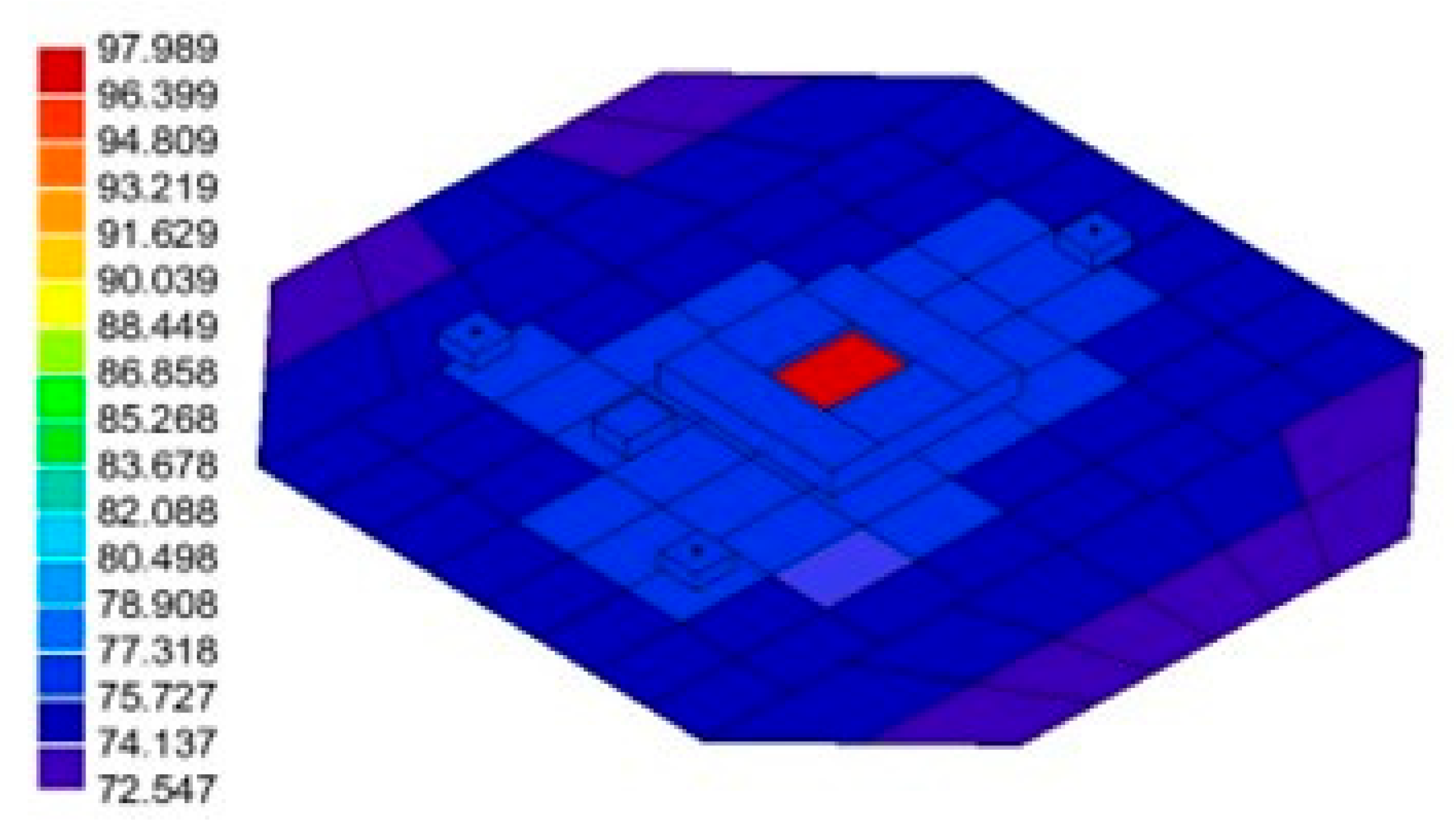
6.2.2. Thermal Simulations
- (a)
- Nominal steady-state;
- (b)
- Mechanical interface temperature: +40 °C;
- (c)
- Ambient temperature: −270.15 °C;
- (d)
- Sun positioned at 18.5° (Sun exclusion angle) from the central axis of the STR, OR Solar irradiation directly falling on the image sensor;
- (e)
- The EEEs are operational (Space Debris mode).
- (i)
- Hot Operational Case (with STR at a Sun exclusion angle of 18.5°)
- (ii)
- Hot Operational Case (with Solar irradiation directly falling on the image sensor)
- (iii)
- STR Cold Non-Operational Case
- (a)
- Nominal steady-state;
- (b)
- Mechanical interface temperature: −10 °C;
- (c)
- Ambient temperature: −270.15 °C;
- (d)
- The EEEs are non-operational (STR fully Off).
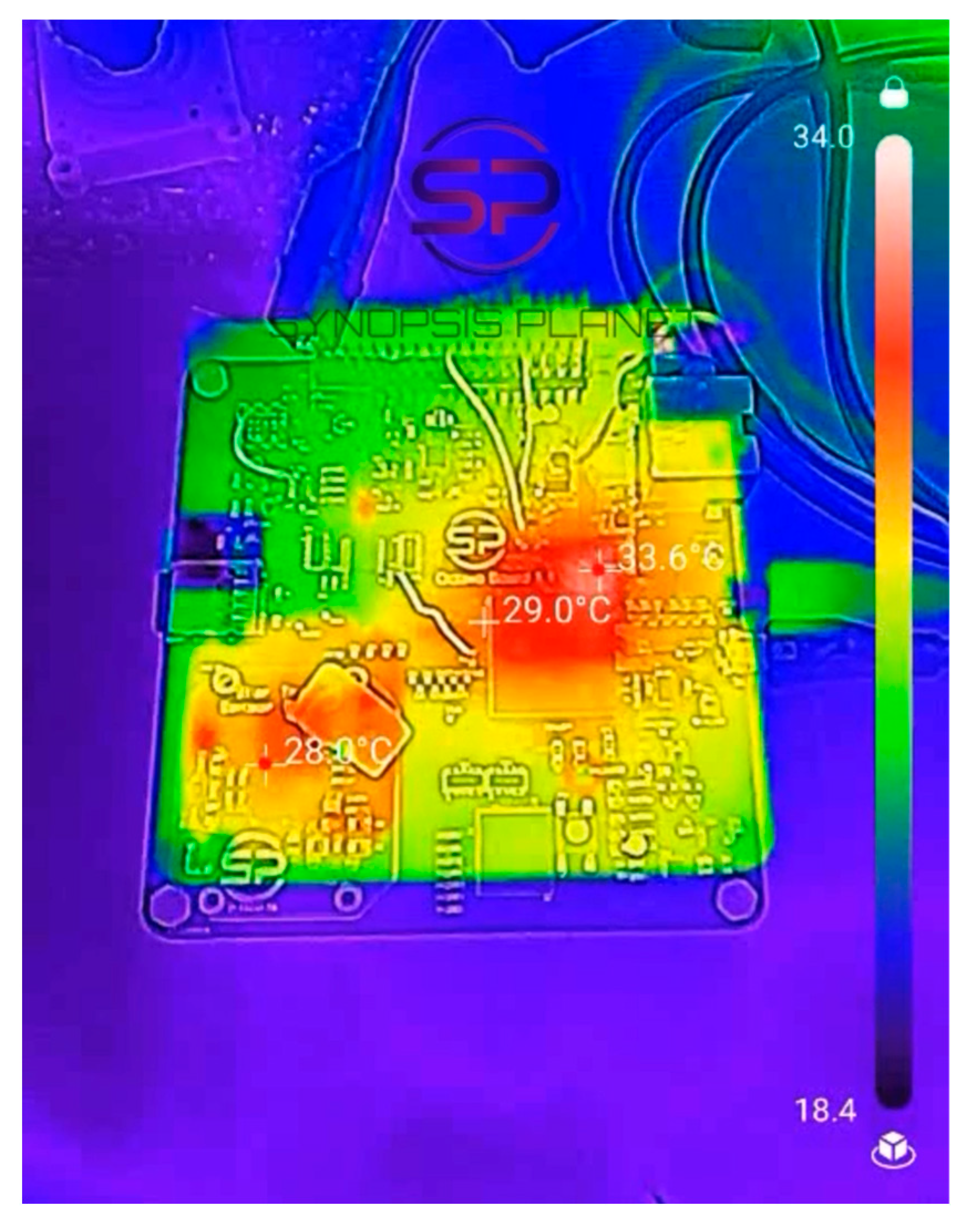
6.2.3. Heat Dissipation Test
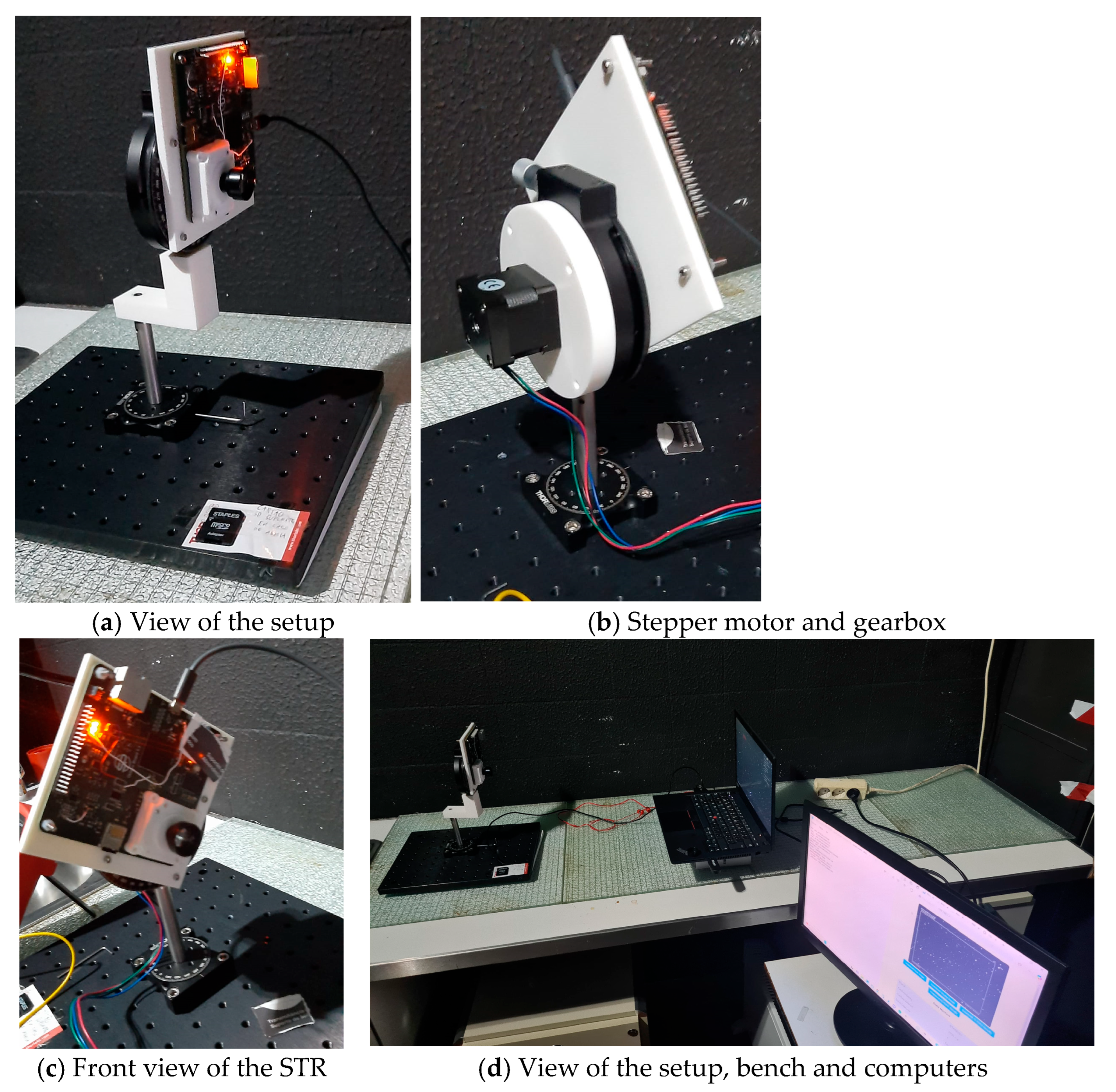
6.3. Attitude Determination Setup Testing
- (a)
- Resolution: 1280 × 960 px;
- (b)
- Sensor size: 4.8 mm × 3.6 mm;
- (c)
- Focal length: 16 mm;
- (d)
- Aperture: f/13.33;
- (e)
- FoV with lens: ≈17°;
- (f)
- Digital gain: 1;
- (g)
- Integration multiplication factor: 1000 (corresponding to an exposure time of 22.2 ms);
- (h)
- Monitor screen brightness was set to the lowest possible level to avoid interference from ambient light;
- (i)
- A reference star image from the sky was generated using Stellarium Web [15], with the sensor and lens parameters configured to match the test conditions.
Test Procedure
7. Conclusions
Author Contributions
Funding
Data Availability Statement
Conflicts of Interest
Abbreviations
| BGA | Ball grid array package |
| CAN-bus | Controller area network bus |
| CCD | Charge-Coupled Device |
| CMOS | Complementary metal–oxide–semiconductor |
| COTS | Commercial Off-the-Shelf |
| CPU | Central processing unit |
| Dec | Declination |
| EDAC | Error detection and correction |
| EEEs | All electronic components |
| eMMC | Embedded MultiMediaCard |
| FoV | Field-of-View |
| FPGA | Field-programmable gate array |
| fps | Frames per second |
| I2C | Inter-integrated circuit |
| LCC | Lead-less chip carrier |
| LEO | Low Earth Orbit |
| OBCS | Onboard computer system |
| PCB | Printed circuit board |
| PLL | Phase-Locked Loop |
| PMU | Power Management Unit |
| PRU | Programmable Real-Time Unit |
| RA | Right Ascension |
| SD card | Secure Digital card |
| SNR | Signal-to-noise ratio |
| STR | Star tracker |
| UART | Universal asynchronous receiver–transmitter |
References
- Zhu, F.; Qin, Y.; Cai, Q.; Chen, X.; Zhang, X. Combining star tracker and gyroscope for remote sensing satellite attitude determination: Algorithm design and performance evaluation with real data. IEEE Trans. Instrum. Meas. 2025, 74, 1–15. [Google Scholar] [CrossRef]
- Fialho, M.A.A.; Mortari, D. Theoretical limits of star sensor accuracy. Sensors 2019, 19, 5355. [Google Scholar] [CrossRef] [PubMed]
- Zacharov, A.I.; Krusanova, N.L.; Moskatiniev, I.V.; Prohorov, M.E.; Stekol’shchikov, O.Y.; Sysoev, V.K.; Tuchin, M.S.; Yudin, A.D. On increasing the accuracy of star trackers to subsecond levels. Sol. Syst. Res. 2018, 52, 636–643. [Google Scholar] [CrossRef]
- Muruganandan, V.A.; Park, J.H.; Maskey, A.; Jeung, I.-S.; Kim, S.; Ju, G. Development of the arcsecond pico star tracker (APST). Trans. Jpn. Soc. Aeronaut. Space Sci. 2017, 60, 355–365. [Google Scholar] [CrossRef]
- Sarvi, M.N.; Abbasi-Moghadam, D.; Abolghasemi, M.; Hoseini, H. Design and implementation of a star-tracker for LEO satellite. Optik 2020, 208, 164343. [Google Scholar] [CrossRef]
- Filho, J.; Gordo, P.; Peixinho, N.; Melicio, R.; Gafeira, R. Payload camera breadboard for space surveillance—Part I: Breadboard design and implementation. Appl. Sci. 2023, 13, 3682. [Google Scholar] [CrossRef]
- Filho, J.; Duarte, P.M.R.; Gordo, P.; Peixinho, N.; Melicio, R.; Valério, D.; Gafeira, R. Space surveillance payload camera breadboard: Star tracking and debris detection algorithms. Adv. Space Res. 2023, 72, 4215–4228. [Google Scholar] [CrossRef]
- Filho, J.; Gordo, P.; Peixinho, N.; Melicio, R.; Garcia, P.; Flohrer, T. Mission analysis of space-based small camera for space debris detection. Adv. Space Res. 2025; 1–24, in press. [Google Scholar] [CrossRef]
- Joergensen, J.L.; Pickles, A.J. Fast and robust pointing and tracking using a second-generation star tracker. In Proceedings of the SPIE 3351, Telescope Control Systems III, Kona, HI, USA, 20–28 March 1998. [Google Scholar]
- Samaan, M.; Theil, S. Development of a low cost star tracker for the SHEFEX mission. Aerosp. Sci. Technol. 2012, 23, 469–478. [Google Scholar] [CrossRef]
- PC/104. Available online: https://en.wikipedia.org/wiki/PC/104 (accessed on 15 April 2025).
- Schmidt, U. ASTRO APS-the next generation Hi-Rel star tracker based on active pixel sensor technology. In Proceedings of the AIAA Guidance, Navigation, and Control Conference and Exhibit, San Francisco, CA, USA, 15–18 August 2005. [Google Scholar]
- Sang, P.; Liu, W.; Cao, Y.; Xue, H.; Li, B. Research on precise attitude measurement technology for satellite extension booms based on the star tracker. Sensors 2024, 24, 6671. [Google Scholar] [CrossRef] [PubMed]
- Spacecraft Star Trackers. Available online: https://ntrs.nasa.gov/api/citations/19700029405/downloads/19700029405.pdf (accessed on 15 April 2025).
- Stellarium Web Online Star Map. Available online: https://stellarium-web.org/.pdf (accessed on 15 April 2025).
- Tetra. Available online: https://github.com/brownj4/Tetra (accessed on 15 April 2025).
- ESATAN-TMS Thermal Modelling Suite. Available online: https://www.esatan-tms.com/index.php (accessed on 15 April 2025).
- ASTRiDE: Automated Streak Detection for Astronomical Images. Available online: https://github.com/dwkim78/ASTRiDE (accessed on 15 April 2025).
- Spacecraft Star Trackers. Available online: https://events.libre.space/event/5/contributions/155/attachments/107/134/3-1%20OreSat%20CubeSat%20System%20Overview.pdf (accessed on 15 April 2025).
- Power Supply Rigol DP932E. Available online: https://www.rigolna.com/products/dc-power-loads/dp900/?srsltid=AfmBOopojkBzd5IPnN_jqkKZnxeZwdLrDTQbl1QQoqrewchzBUG3_nwl (accessed on 15 April 2025).
- Thermal Camera TC001 Plus. Available online: https://eu.topdon.com/es/products/tc001-plus (accessed on 15 April 2025).
- Space Debris Detector and Star Tracker, Heat Dissipation Test. Available online: https://www.synopsisplanet.com/our-products/space-debris-detector-and-star-tracker (accessed on 15 April 2025).


| Operating Mode | Minimum (W) | Medium (W) | Maximum (W) |
|---|---|---|---|
| Boot | 0.57 | 1.18 | 1.96 |
| Idle | 0.60 | 0.61 | 1.16 |
| Standby | 0.83 | 0.98 | 1.70 |
| Video (5 fps) | 0.63 | 1.22 | 2.24 |
| Space Debris | 0.82 | 1.23 | 1.85 |
| ASTRiDE | 0.89 | 1.39 | 1.92 |
| TETRA3 | 0.60 | 1.08 | 1.87 |
| Variables | Stellarium (deg) | Tetra3 (deg) | Difference (%) |
|---|---|---|---|
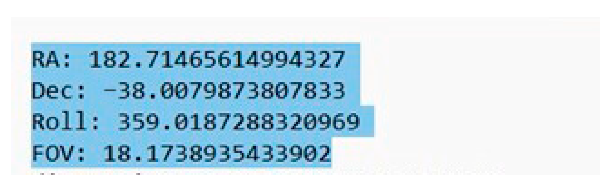
| RA | 184.73 (12 h 18 m 55.37 s) | 182.71 | 1.09 |
| Dec | −38.27 | −38.00 | 0.07 |
Disclaimer/Publisher’s Note: The statements, opinions and data contained in all publications are solely those of the individual author(s) and contributor(s) and not of MDPI and/or the editor(s). MDPI and/or the editor(s) disclaim responsibility for any injury to people or property resulting from any ideas, methods, instructions or products referred to in the content. |
© 2025 by the authors. Licensee MDPI, Basel, Switzerland. This article is an open access article distributed under the terms and conditions of the Creative Commons Attribution (CC BY) license (https://creativecommons.org/licenses/by/4.0/).
Share and Cite
Arribas, B.N.; Maia, J.G.; Castanheira, J.P.; Filho, J.; Melicio, R.; Onderwater, H.; Gordo, P.; Duarte, R.P.; Silva, A.R.R. Dual-Purpose Star Tracker and Space Debris Detector: Miniature Instrument for Small Satellites. J. Sens. Actuator Netw. 2025, 14, 75. https://doi.org/10.3390/jsan14040075
Arribas BN, Maia JG, Castanheira JP, Filho J, Melicio R, Onderwater H, Gordo P, Duarte RP, Silva ARR. Dual-Purpose Star Tracker and Space Debris Detector: Miniature Instrument for Small Satellites. Journal of Sensor and Actuator Networks. 2025; 14(4):75. https://doi.org/10.3390/jsan14040075
Chicago/Turabian StyleArribas, Beltran N., João G. Maia, João P. Castanheira, Joel Filho, Rui Melicio, Hugo Onderwater, Paulo Gordo, R. Policarpo Duarte, and André R. R. Silva. 2025. "Dual-Purpose Star Tracker and Space Debris Detector: Miniature Instrument for Small Satellites" Journal of Sensor and Actuator Networks 14, no. 4: 75. https://doi.org/10.3390/jsan14040075
APA StyleArribas, B. N., Maia, J. G., Castanheira, J. P., Filho, J., Melicio, R., Onderwater, H., Gordo, P., Duarte, R. P., & Silva, A. R. R. (2025). Dual-Purpose Star Tracker and Space Debris Detector: Miniature Instrument for Small Satellites. Journal of Sensor and Actuator Networks, 14(4), 75. https://doi.org/10.3390/jsan14040075