1. Introduction
The evolution of global electricity production by photovoltaic sources in the last decade has increased over ten times, and still, it is expected to keep growing in the next few years. Furthermore, in recent years, several nations have expanded policies for installing photovoltaic (PV) plants to replace nuclear and fossil power generation plants [
1,
2,
3,
4]. Therefore, with the consistent growth of photovoltaic conversion systems, the improvement of smart inverters, which perform the interconnection between electrical generation and smart grids, becomes crucial. The PV distributed generation equipment and systems are standardized [
5] by the IEEE 1547-2018 Standard and by the IEC 61727, which refer to distributed energy resources and PV generation connected to the power grid, respectively.
Recent works have proposed the management of functions, control actions, and power requirements for smart inverters, such as the Advanced Renewable Energy Distribution System (DREAMS). This system was developed and installed in the district of Fongshan by the Taiwan Power Company (Taipower), where the power factor is autonomously adjusted to absorb reactive energy when overvoltages occur in the distribution network [
6]. In [
7], the maximum power point tracking (MPPT) algorithm was applied, as well the limited power point tracking (LPPT) algorithm was adjusted considering external commands, the electrical grid dispatch capability. The adjustment was designed and implemented using discrete-event flowcharts. Likewise, the scheme proposed in [
8] also uses discrete-event flowcharts to design the management system for a smart inverter with energy storage. Similarly, in [
9], a management system was used to control the energy generation from wind turbines, performing the control of the power dispatch to the electric grid and the LVRT function.
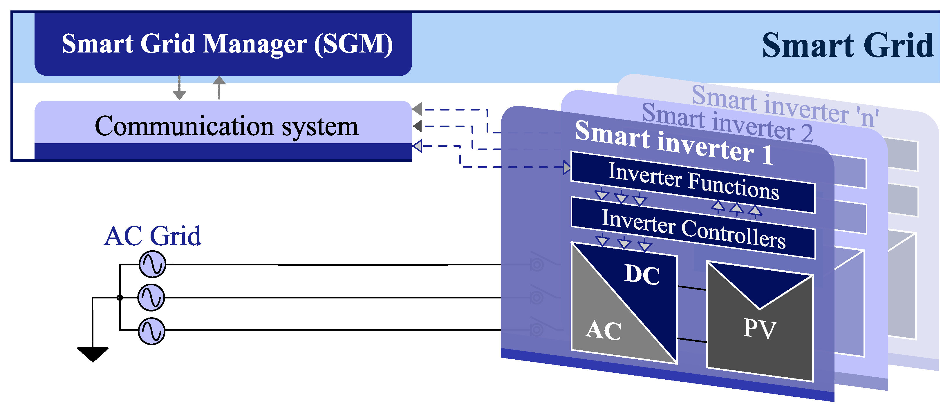
Figure 1 shows a smart grid manager (SGM) communicating with smart inverters.
A cooperative control method distributed in two layers was proposed in [
10] for microgrid (MG) systems’ management. The proposed control architecture consists of a control layer for the MG and a control layer for networks of microgrids (NMGs). In the MG layer, the secondary and primary controls share energy between the distributed generators (DGs) and the frequency/voltage reference to follow in each MG. In the NMG layer, the tertiary control allows the power regulation that flows through each MG common coupling point in a decentralized manner. Besides, the quaternary control restores the system frequency and the AC bus critical voltage to its nominal values and ensures the precise sharing of energy among the MGs.
In [
11], a distribution network feeder bus in the IEEE Standard 34 was adapted and managed as an MG, adding distributed generations and load profiles. An energy management strategy was defined to coordinate the transitions and to minimize the voltage and frequency transients. In [
12], an energy-sharing control approach was presented with the integration of multiple intermittent distributed generators (IDGs). The approach was based on inverters using an aperiodic data transmission scheme, and its purpose was to maintain a balance between active energy supply and demand. According to the proposed control strategy, each MG bus has an associated bus agent. In [
13], a supervisory control was proposed for the management and control of a customized energy generation park. Three modular supervisors were synthesized using the TCT software (a computation tool for Supervisory Control Synthesis [
14]) and simulated using Simulink
[
15].
In the power generation systems mentioned above, a management system coordinates the transitions between modes, protection requirements, and standard procedures for different operation points. The primary role of a smart inverter manager (SIM) is to define in which mode the system must operate at any moment, given the conditions from the system parameters and the SGM commands. The SIM also defines the power references for the active and reactive power that must be dispatched by the inverter to the grid.
In order to improve the smart grids’ interoperability, an additional layer can be included in the smart inverter control strategy to deal with SGM commands and inverter function algorithms/controllers. The separation of control levels within a smart inverter through the proposed layers is characterized as one of the main contributions of this paper, since this delimitation allows the application of different methodologies for SIM design, as well for the converters’ controllers. Besides, it can make it easier to use different frequencies of operation for converters, control hierarchies, and information flows from each layer and between layers.
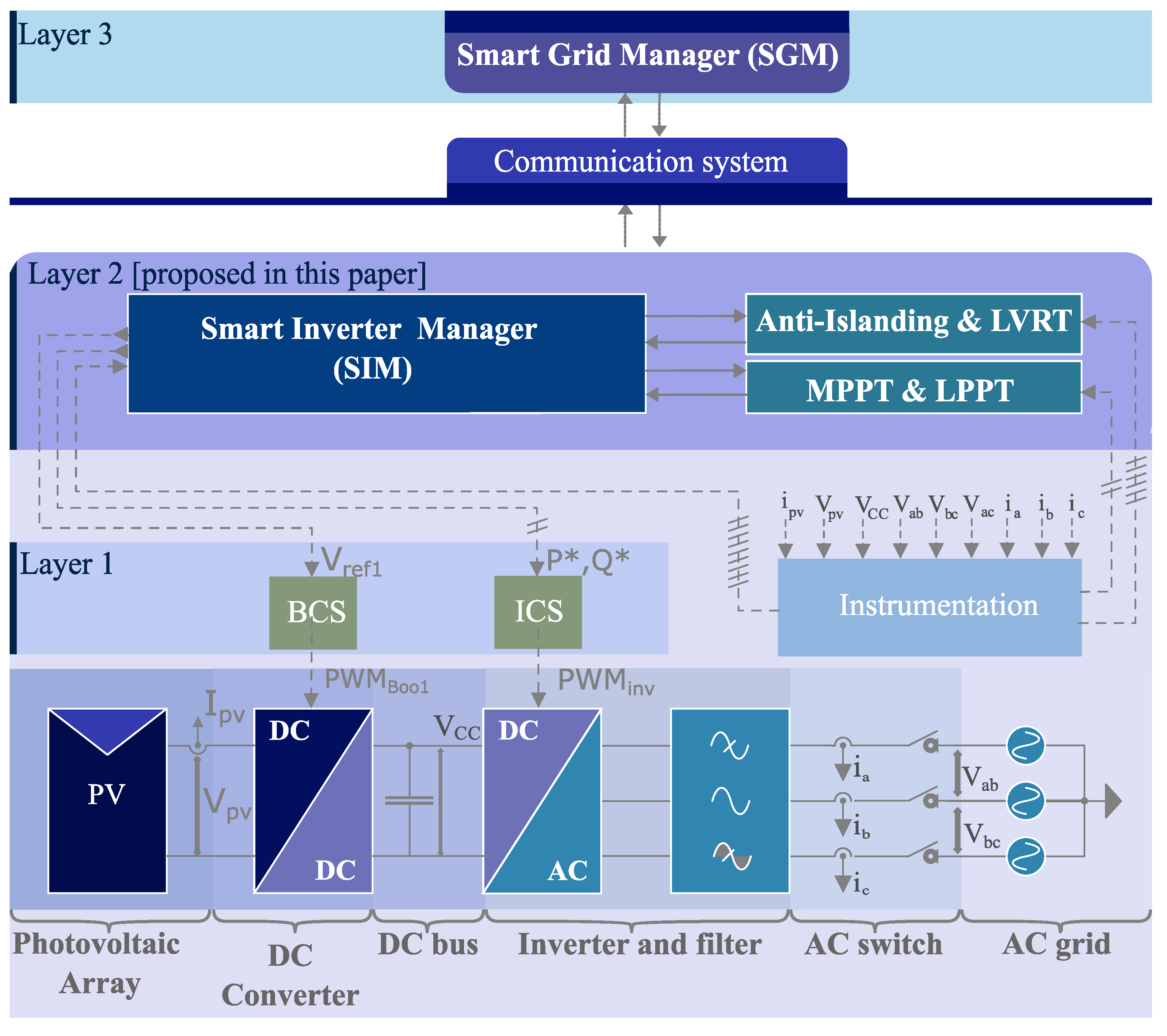
Figure 2 shows the additional layer proposed in this paper labeled as “Layer 2”. This layer includes the SIM and additional algorithms, such as the MPPT, the limited power point tracking (LPPT), LVRT treatment, and islanding. The SIM communicates with the SGM, a control layer above (Layer 3), through a communication system. The SIM also interacts with Layer 1, where the real-time controllers for the inverter (ICS) and DC/DC converters (BCS) are located. Moreover, since the transitions in the inverter and SGM commands can be seen as events, this paper applies supervisory control theory [
16] for the development of the SIM. Using the SCT approach, it is possible to reduce the risks that some state of the system or function is not considered, in addition to obtaining an entity called the
supervisor, who consistently implements the designed system. Preliminary results were reported in [
17], where the inverter management issue was initially investigated. This paper provides the design details, algorithms, and an extended investigation considering both RTDE and experimental evaluation. Considering these issues, the main contributions of this work are:
The delimitation of a management layer that includes a function manager, LVRT, islanding algorithms, the MPPT, and the LPPT for smart inverters;
The design of a smart inverter manager (SIM) and the inverter implementation using supervisory control theory (SCT).
The paper is organized as follows:
Section 2 describes the scope of DG inverters;
Section 3 describes the functions that are performed by the smart inverter;
Section 4 presents the SIM design and its implementation using SCT;
Section 5 describes the smart inverter implementation with results for real-time emulation with a Typhoon HIL 602+ device [
18].
2. Problem Formulation
The necessary parameters the SIM must meet, how it can act, and the resources of supervisory control theory applied to the SIM are detailed in the following subsections.
2.1. Photovoltaic Energy Conversion Systems
The PV energy conversion systems can be composed of the PV panel arrays, DC/DC converters, DC bus, inverter, passive filter, AC connection switch, and instrumentation circuits, shown in
Figure 2. The BCS represents the boost control system, and ICS is the inverter control system. These control systems are at a low level in the conversion system (Layer 1). The management layer (Layer 2) is composed basically of the SIM, the algorithms for the detection and treatment of islanding and LVRT, and the MPPT and LPPT algorithms. The SIM communicates with the smart grid manager (Layer 3) through a communication system using international standards for PV systems (SunSpec in this work).
Control Systems for the Smart Inverter
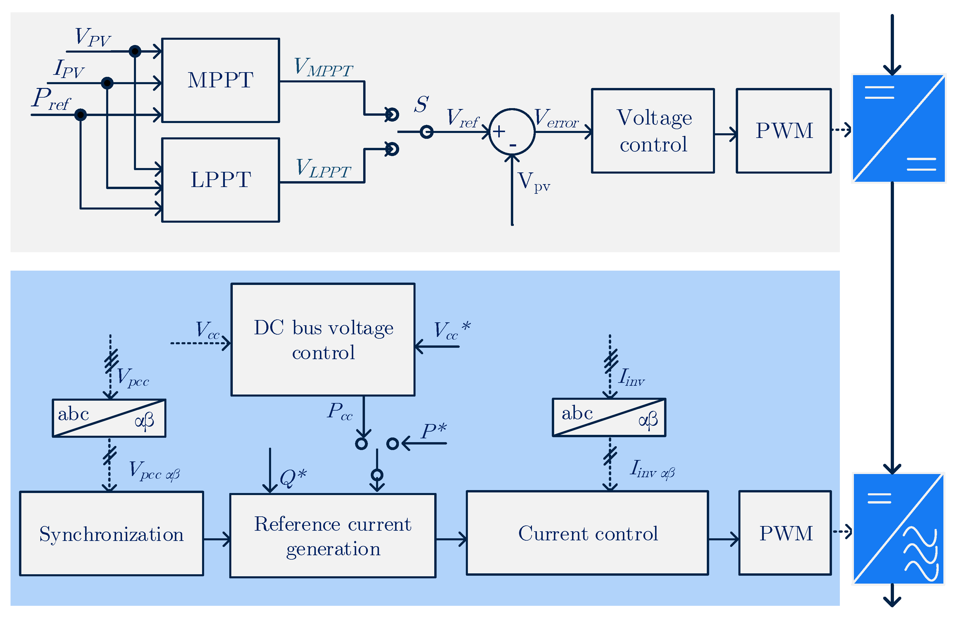
The control of the boost converter input voltage (
) is usually chosen to control the power extraction from the PV array using the MPPT or LPPT algorithms [
19]. To control
, it is possible to change the duty cycle of PWM
Boo1, which activates the converter’s semiconductor switch. The reference and control generation diagram of this converter is shown in the upper block of
Figure 3, where
is the output current of the PV array,
is the power reference defined by the SIM, and
is the reference voltage generated by the MPPT or LPPT algorithm. In this scheme,
S is used to select whether
will be calculated by the LPPT or MPPT algorithm [
20].
By controlling the output current of the three-phase inverter, it is possible to change the active and reactive power dispatched to the grid and to control the voltage on the DC bus. In the lower block of
Figure 3, the main elements of the inverter control system are represented. They are synchronization, reference current generation, the DC link voltage controller, the inverter output current controller, and PWM modulation. In this figure also, the sign
represents the three-phase voltages at the connection point,
is the inverter’s three-phase output currents,
is the DC bus voltage,
is the DC bus voltage reference,
is the active power reference to control the DC bus,
is the SIM-defined active power reference, and
is the reactive power reference.
The BSC and ICS can be properly designed to keep the smart inverter within the restrictions of operation and in compliance with the quality parameters, interoperability, and safety defined in national and international standards.
2.2. Standards
The IEEE 1547-2018 [
23] establishes several requirements for smart inverters.
Table 1 presents only the IEEE 1547-2018 requirements understood as those that are the responsibility of and within reach of the SIM.
The SIM also needs to check for abnormal operating conditions such as islanding, mains voltage drop, over-voltage, and output over-current. The anti-islanding and LVRT functions are performed externally to the SIM, as they require sophisticated detection and treatment algorithms. The network parameters must be constantly monitored in order to allow the SIM’s management. Besides, the communication with the SGM is necessary to obtain the commands that the SIM must perform.
The functions that the SIM must perform within the SIM scope are divided into:
Protection functions: over-voltage, over-current, frequency outside the limits, and protection against the injection of the DC component to the grid;
Essential functions: connect (Con), disconnect (Dis), and cease dispatch (CeasDisp);
Operating modes: limited active power (Plim), specified reactive power (Qesp), specified power factor (FP), and specified active–reactive power (PQ).
2.2.1. Protection Functions
If the monitored parameter leaves the standards’ limits, some of the events
Pro_CeasDisp or
Pro_Dis are triggered (set to one), identifying the need for ceasing supply or disconnection [
23]. Such a signal is understood as a noncontrollable event of the protection functions.
2.2.2. Essential Functions
For connection to the grid, it is necessary that the SGM request/authorize the execution of this function (event SGM_Con = 1). The SIM understands that the SGM commanded the connection, and it starts the connection function enabling the event Con_in. During the execution of the connection function, the grid parameters are checked, such as voltage and frequency . If these parameters are within the acceptable limits, the AC connection switch is activated, , and the system waits for a specified time for stabilization. Then, the active power reference ramp is initiated and dispatched to the grid.
For the cease dispatch function, the SGM sets the event SGM_CeasDisp to one, or some protection function may request the execution of the cease dispatch function, taking Pro_CeasDisp to one. Right after the execution of any of these events, the SIM starts the function by setting the event CeasDisp_in to one, and the apparent power reference is reduced in ramp with the rate defined by the SGM, while the connection switch remains closed. In the disconnection function, the connection switch is opened after the inverter apparent output power reaches close to zero.
2.2.3. Operating Modes
For the execution of specific operating modes, the SGM sets the respective mode event to one (e.g., to execute the limited active power mode (Plim), the GSM sets the event SGM_Plim to one), then the SIM enables the respective event (Plim_in) to execute the required function.
The following operating modes are defined according to the IEEE 1547-2018 Standard:
specified reactive power, specified power factor, limited active power, specified active–reactive power. The modes
voltage-active power, voltage-reactive power and
active–reactive power were not included in the SIM because they are more suitable to be included in the SGM in order to coordinate several inverters [
23].
The active and reactive power references are implemented in ramp, with the magnitude and rate defined by SGM. In specified reactive power mode, is defined by the SGM, and is set as the residual value of the active power that the drive can currently dispatch. In the specified power factor mode, the inverter dispatches the maximum active power and provides the reactive power in order to achieve the power factor defined by the SGM. In the limited active power mode, the maximum is specified by the SGM, while is set to 0 VAr. In the specified active–reactive power mode, and are defined by the SGM up to the inverter capability ().
2.3. Remote Management Features
Smart grids consist of markets that operate from centralized electricity generation to the final consumer and generation distributed by the system operator, electric service providers, energy transmission and distribution, and the final consumer with their consumption and production technologies of electricity [
24]. The information exchanged between the PV system and the SGM can follow the standards of the International Industrial Alliance of Photovoltaic Systems, the SunSpec Alliance. The adoption of the SunSpec standard allows applying standardized information and obtaining improved system interoperability [
25]. A smart inverter can apply these standards using at least the following models: common, nameplate, basic settings, measurements status, and immediate controls.
2.4. Smart Inverter Function Manager
The SIM operates using commands from the SGM, using a communication interface, and information on the amount of power that each DC/DC boost converter extracts at any moment from the PV arrays and other system measurements provided by the instrumentation circuits. From the SGM and SI information, the SIM defines which function should be performed at any moment. It calculates the active () and reactive () power references that the inverter’s real-time control should achieve, the power that the boost converters must extract from the PV panels, and controlling the AC switch to interface with the power grid.
For SIM modeling, the overall set of events is defined, consisting of
, where
is the set of controllable events and
the set of noncontrollable events.
is composed of the commands for executing the functions, e.g., the event
Qesp_in executes the specified
reactive power mode. The set
consists of the SGM commands for inverter function execution, e.g.,
SGM_Qesp, as well the protection functions to execute the
cease dispatch function (
Pro_CeasDisp) and
disconnect (
Pro_Dis). The set of events
is described in
Table 2.
2.5. SIM Automata
The SIM operation is characterized by the observance of events, without prior knowledge of when they will occur, and decision-making between functions. As a result, the resources of supervisory control theory (SCT) [
16] are used for the design and implementation of this manager. The use of SCT increases the manager’s robustness since, if the plant and its specifications are modeled in a coherent way, it is possible to obtain an entity called a supervisor that implements the manager with all its possible states and transitions. In addition, an optimized implementation can be obtained when compared to a simple approach using only cases and/or switch cases, since the supervisor is synthesized in an external environment, and only the vectors that represent the supervisor are accessed during its execution in a digital signal processor (DSP), thus reducing the computational cost. The automaton that describes the general behavior of the SIM is called
plant,
G, which is a deterministic finite-state automate (DFSA), which can be defined as:
where:
: set of events that can occur in the SIM, define the finite alphabet;
Q: finite set of possible states of the SIM;
: initial state of the SIM;
: subset of marked states, where the SIM can remain stable and secure;
: the transition relationship between possible states in the plant.
The transition from a
state to a
state, determined by the occurrence of the
event, is described as
. The automata describe formal languages (
L) through the occurrence of chains of events (
s) contained in the finite alphabet (
), as well as the marked language (
), which represents the set of all chains that lead to marked states. Therefore, the languages of a DFSA called
A are defined as:
The modeling of automata can be performed from the synchronous composition of several automata. Considering
the synchronous composition of
A and
B is defined as:
The specifications (E) are modeled to incorporate the plant restrictions. Therefore, it is possible to model the SIM specifications (a DFSA) in a modular way, that is the procedures to perform each function that the manager can coordinate are modeled on a specification, and then, the synchronous composition of all specifications is performed to obtain only one specification. With the automata that describe the plant (G) and its specifications (E), an automaton called the supervisor (S) is synthesized as a control structure for G.
A
supervisor behaves as a map,
, associated with a language
that, after any chain of events belonging to the
plant alphabet, observes possible events in the
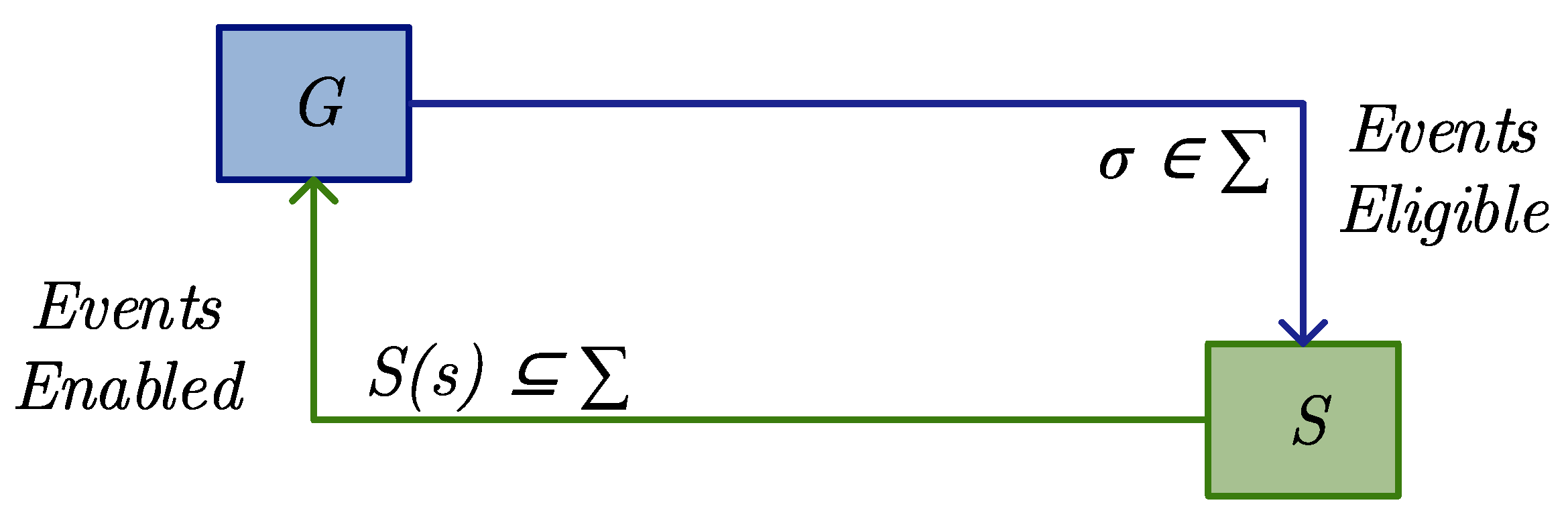
plant and enables them in sequence, according to the control flow shown in
Figure 4. The
events occur spontaneously in the
plant. When
is observed, the
supervisorS updates the set
of enabled events. Possible events in the
plant that do not belong to
are those that are inhibited by the control action. The set of
strings that survive under control represents the behavior generated in a closed-loop and is given by the language
[
16]. The
supervisor implementation takes into account the SIM’s
specifications, enabling controllable events according to the evolution of the system over the course of other events.
The
supervisory S is defined in such a way that
e
, where
K is the desired behavior
. The calculation of
is an iterative process [
26], where the prohibited states of the
E automaton that represents the specification are identified and removed. A forbidden state
x is defined as that after some
,
exist, such that
.
For the calculation of
, the following steps must be carried out: identify and remove prohibited states in
E; test the block on
E, checking that each
chain is prefixed to a marked chain and that
q is accessible
. For the synthesis of the supervisory control, it is important to highlight that the computational complexity is polynomial in the number of states of
G and
E; however, they present an exponential increase in the number of states, which leads to possible practical nontreatment of the implementation of the obtained supervision [
26].
3. SIM Design Using SCT
For the SIM design using the automata theory, it is considered that the system to be controlled (
plant (
G)) and its
specifications (
E) are modeled so that it is possible to observe all events, and only the controllable events are disabled. The
supervisor (
S) aims to describe the possible transitions in the
plant in compliance with the defined restrictions.
S interacts with
G in a closed-loop structure, wherein
S observes the events occurring in
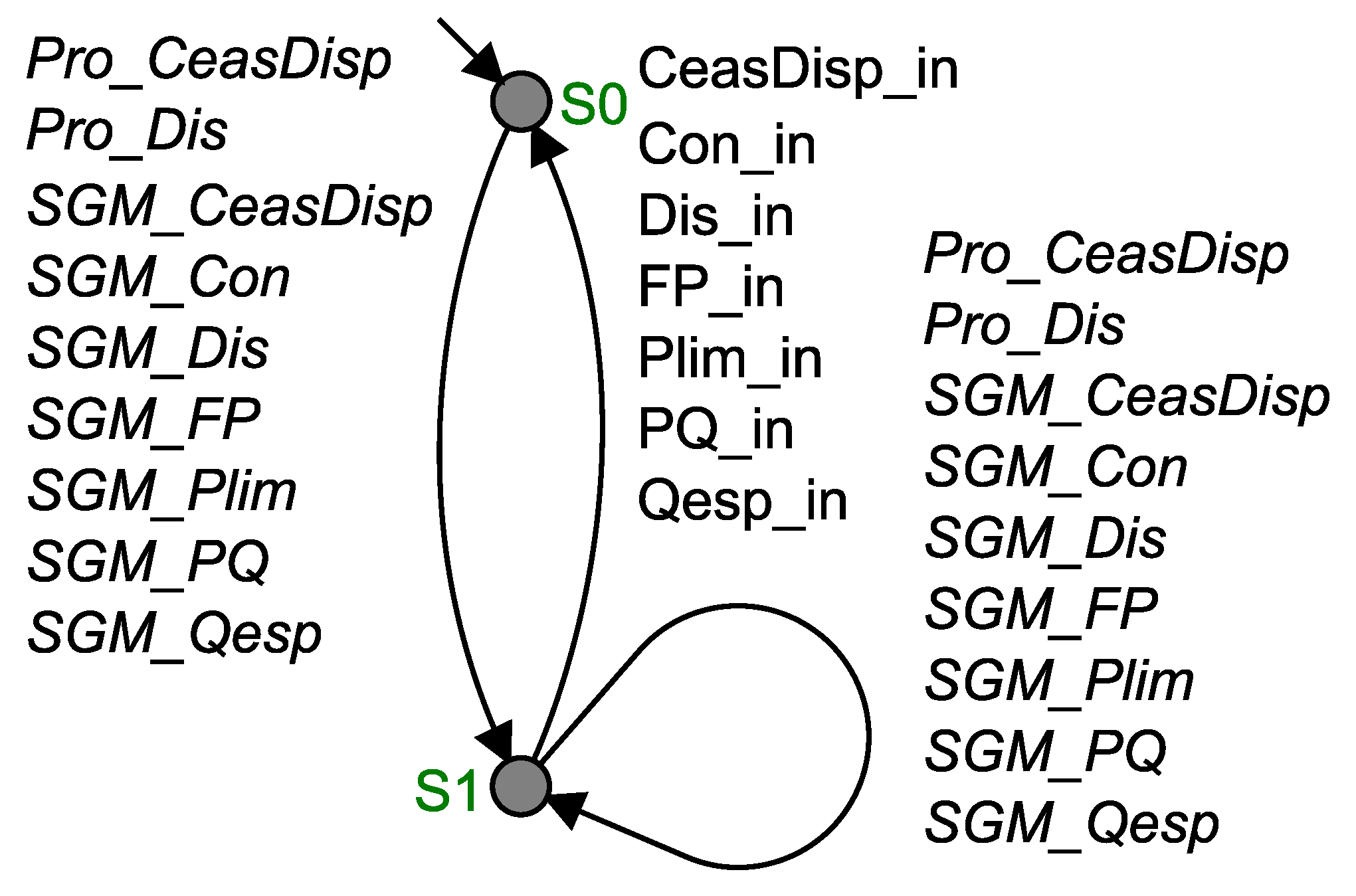
G and defines which events are allowed to occur, given the restrictions imposed. The SIM is modeled as an automaton called “SIM plant”, shown in
Figure 5. The manager consists essentially of a machine that monitors the noncontrollable events (
) and, from the occurrence of at least one of them, evokes the function corresponding to this event, enabling the controllable events (
). In this automaton, both the initial (
) and final states are identified (S0 and S1).
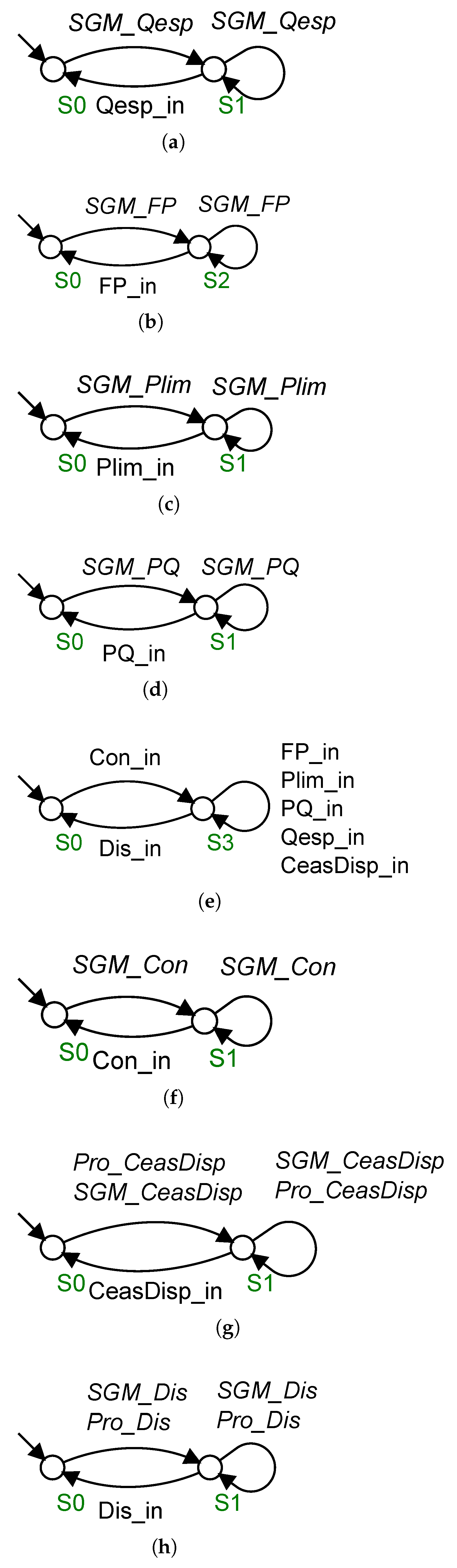
Figure 6 shows the modeled specifications, which can be summarized as:
E_Prefe defines the preference for executing the connection function in relation to the other functions that the SIM must coordinate;
E_Cone defines the order of execution of the events related to the connection function (when the
SGM_Con event is executed, the
Con_in event is enabled);
E_CesFor specifies that the event
CeasDis_in is enabled when the event
SGM_CesFor or
Pro_CeasDis is activated;
E_Disc describes a similar behavior of
E_CesFor;
E_Qesp defines the execution order of the controllable event
Qesp_in, in the execution of noncontrollable event of
SGM_Qesp;
E _FP defines the execution order of events related to the
specified power factor mode;
E_Plim is similar to
E_FP;
E_PQ is also similar to
E_PQ. The specifications can be composed in
E, using synchronous composition, defined as:
.
E_Prefe defines that any function is only enabled after the connection function has already been executed (the system must be connected to perform other functions). The specifications “E_Cone”, “E_Qesp”, “E_FP”, “E_Plim” and “E_PQ” define the order of execution of the events in the respective functions, where the supervisor enables the execution of a controllable event of the function from the noncontrollable event related to that function.
Procedures for the SIM Implementation
The SIM supervisory automaton
S was designed to be implemented in a computational system. In this work, it was implemented in a commercial DSP device using the C language. The DESLAB software [
27] was used to calculate
, where
specifications are declared and their synchronous composition (
E) is obtained and the
plant (
G) is declared and the
supervisor (
S) is summarized. The resulting supervisory automaton contains 4444 transitions (NTRN) and 444 states (NESTED). The
S automaton conversion into C code was carried out using the software DESLAB, according to Algorithm 1. This conversion is performed through chained lists and implements the supervisor through a state machine in the Mealy model, where the outputs are declared in each transition event.
| Algorithm 1 Supervisor |
| Input:,, event[NTRN], in_state[NTRN], rfirst[NST], rnext[NTRN] |
| Output: occur_event |
- 1:
LoaEve(); //Buffer loading with some event having occurred - 2:
if (n_buffer == 0) then - 3:
GenRanEve(); //Generation of a random controllable event - 4:
else - 5:
occur_event = buffer[0]; - 6:
n_buffer–; - 7:
k = 0; - 8:
while (k < n_buffer) do - 9:
buffer[k] = buffer[k + 1]; - 10:
k++; - 11:
end while - 12:
end if - 13:
k = rfirst[current_state]; //Automaton player - 14:
if (k == 0) then - 15:
break; //State does not exist in the supervisor - 16:
else - 17:
while (k > 0) do - 18:
k–; - 19:
if (event[k] == occur_event) then - 20:
current_state = in_state[k]; - 21:
mealy_output = 1; - 22:
break; - 23:
end if - 24:
k = rnext[k]; - 25:
end while - 26:
end if - 27:
if (mealy_output) then - 28:
return occur_event //Returns event, if valid - 29:
mealy_output = 0; - 30:
occur_event = −1; - 31:
end if
|
The C code is composed of a set of vectors with the initial states (in_state[NTRN]), the transitions (event[NTRN]), and the transition relationships of the automaton (rfirst[NST] and (rnext[NTRN]). In Algorithm 1, the LoaEve() function is initially called, where it is loaded in a buffer with some having occurred and storing the noncontrollable events having occurred, in the occurrence order and according to the attribution order described in the implemented code routine. If the buffer is empty, the GenRanEve() function is called, which generates a random event . Then, the supervisor’s current state (Line 13) is identified. If the current state is valid, then the first noncontrollable event stored in the buffer is handled or the random controllable event generated in the case of the empty buffer. The treatment of this event is carried out in the “if loop” (Line 19), where it is verified whether the event having occurred was enabled by the supervisor for the current state. If this event is valid, then the current_state will be the next state, , and the supervisor captures the occurred event, then the controllable event is enabled.
4. Real-Time Domain Emulation Results
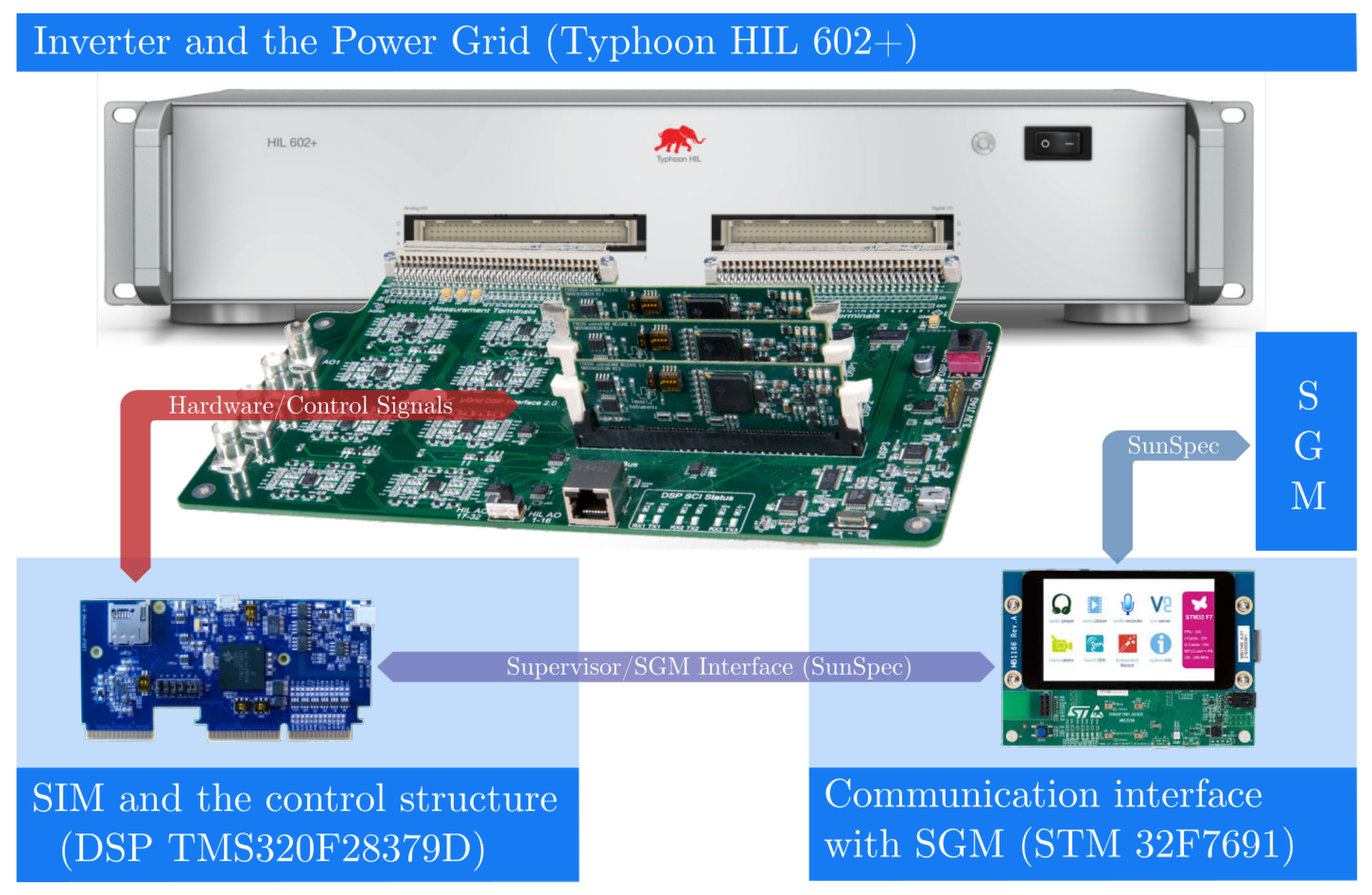
The validation of the SIM design and its performance evaluation were carried out using a prototype with a real-time domain emulation (RTDE) of a PV system. The PV system’s power electronic arrangement was emulated in a hardware-in-the-loop (Typhoon HIL 602+) device, allowing us to obtain results very close to the real case application. The DSP TMS320F28379D was used for the SIM supervisor (S) and the real-time controllers’ implementation. The sampling frequency of the inverter-side control was 18 kHz, while the PV-side converter controllers’ switching rate was 36 kHz. The MPPT algorithm update rate was 10 Hz.
The STM32F7691 microcontroller unit based on the ARM
Cortex
-M7 core was used to perform the communication interface with the SGM, as shown in
Figure 7. The STM32F7691 board also includes a touchscreen display, which was used as the human-to-machine interface.
The PV array was considered with 1000 W/m
@ 25
C, and the main grid parameters [
28,
29] are given in
Table 3.
Several SIM functions were evaluated: connection (Con), limited active power (Plim), specified active–reactive power (PQ), specified reactive power (Qesp), specified power factor (PF), and disconnection (Des).
4.1. Operating Modes
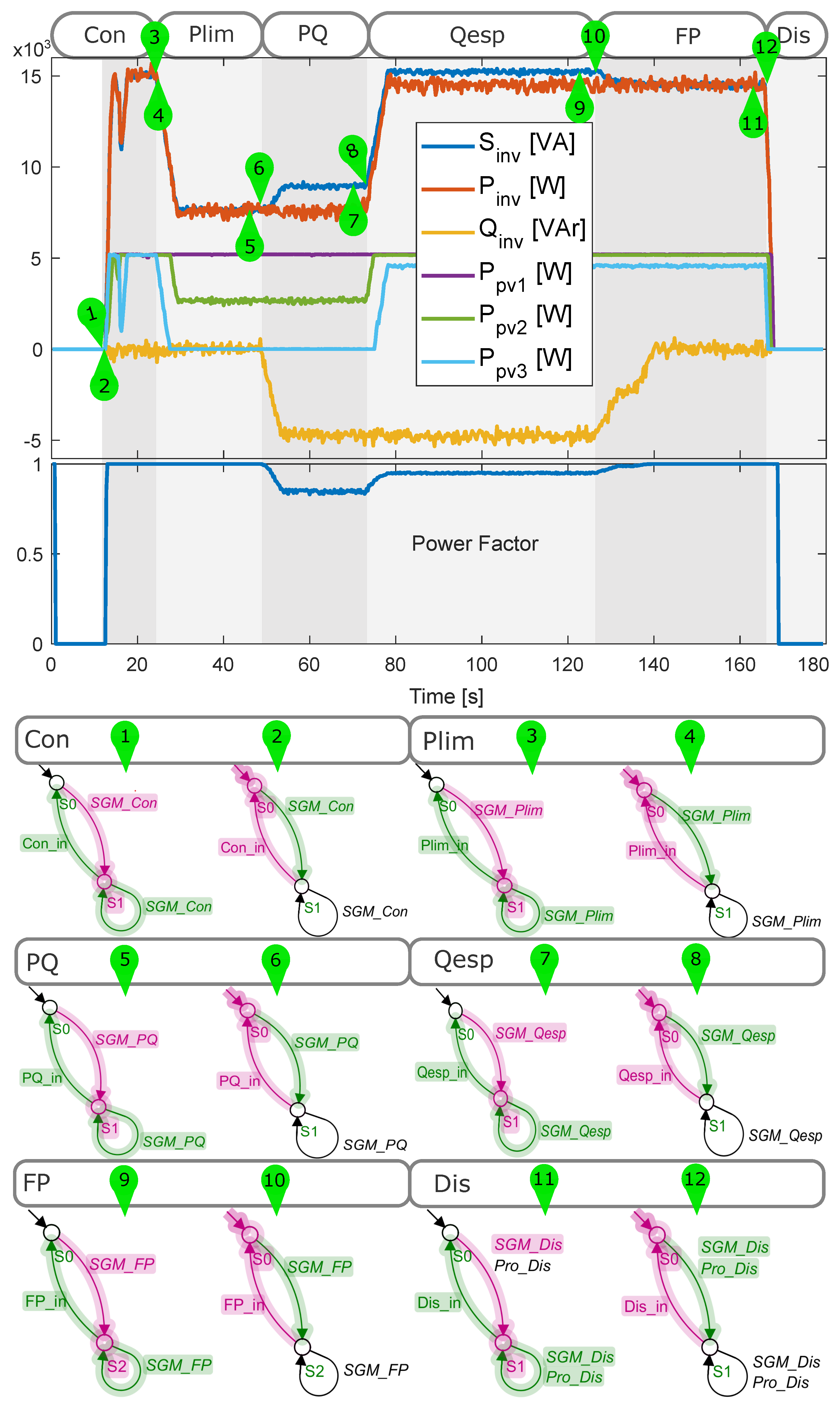
The operating modes (OMs) were evaluated using the described RTDE-DSP system. The signals of the active, reactive, and apparent power of the inverter output, as well the ones produced by the three PV arrays and the power factor of the inverter output current (Phase A) are shown in
Figure 8. The automata of the specifications for each mode are shown, and the pink transitions highlight those that occurred at a given moment in the simulation indicated by the green balloons, while the green transitions indicate those allowed to occur.
During the execution of the
connection function, the energy dispatched to the electrical network was 15 kVA up to 25 s. The SIM then reduced the dispatched active power to 8 kW according to the SGM’s request, indicating the
limited active power mode. During the
specified active–reactive power mode, the dispatched reactive power increased to −5 kVAr, according to the SGM’s reference. At 75 s, the
specified reactive power mode started, where the reactive power reference remained at −5 kVAr, and the dispatched active power was defined according to the inverter’s available power. During the
constant power factor mode, started at 125 s, the SIM led the power factor to the unit (
). At the end, the
disconnection function was required by the SGM. Thus, the SIM reduced the PV and inverter power output references to zero at 170 s, as shown in
Figure 8.
From the RTDE and experimental analysis, it is possible to verify the fast response of the SIM to the SGM’s commands. Immediately after the occurrence of noncontrollable events, such as SGM_Con, the SIM identified the command and then performed the SGM’s request. Within each function, the power references were calculated and the respective inverter controllers updated. The SCT approach applied for the SIM design allowed achieving the energy balance between the DC and AC sides.
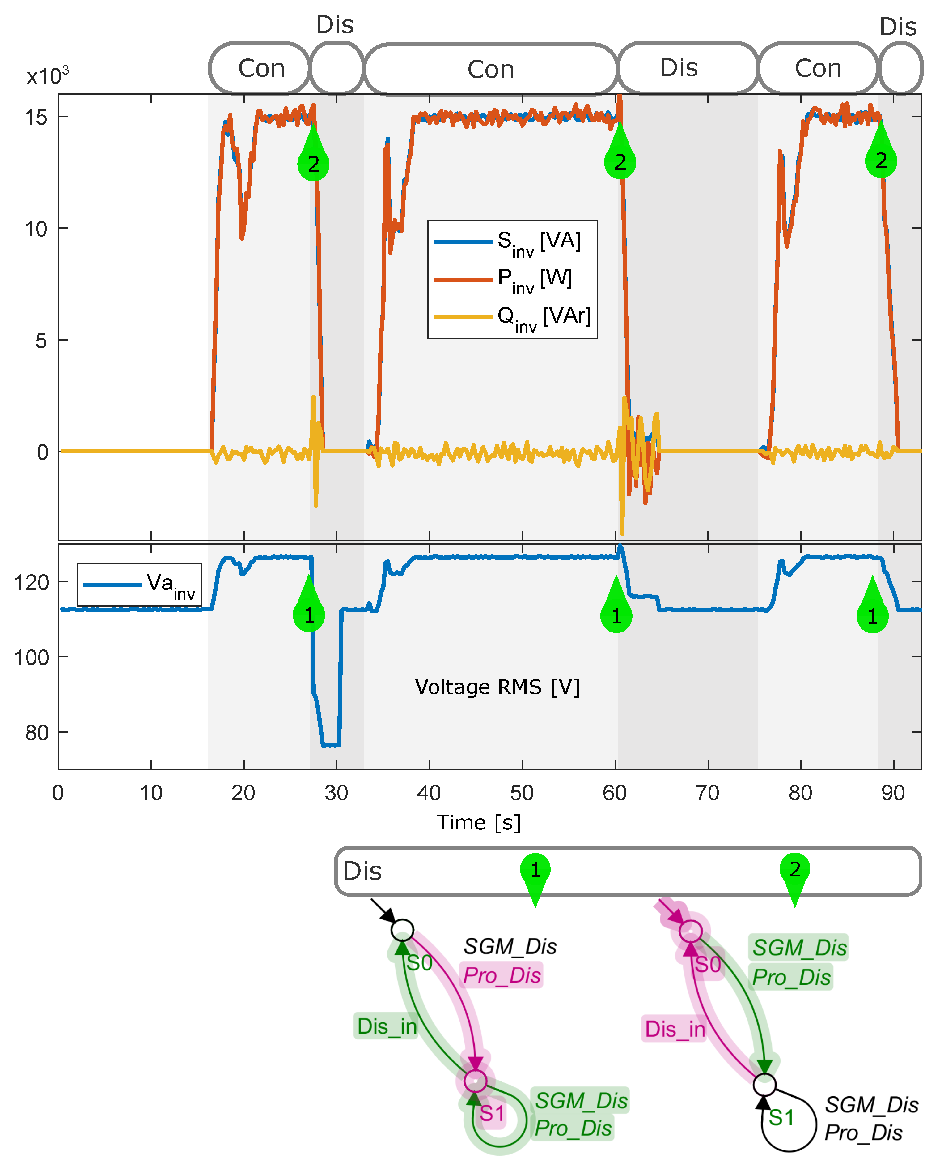
4.2. Protection Functions
Another analysis was carried out to evaluate the SIM’s behavior when faults occurred in the electrical system, such as phase-to-ground short-circuit, phase-to-phase short-circuit, and distorted harmonic grid. The power profiles dispatched by the inverter and RMS inverter voltage (Phase A) are shown in
Figure 9. The automaton of the
disconnection specification indicated the instant when the disconnection signal from the protection functions was set. Thus, the SIM commanded the PV system to execute the function
disconnect.
Table 4 shows the comparison of the SIM’s response time to the SGM’s commands and protection functions for each one defined in the IEEE 1547-2018. In the proposed implementation, all response times were below the IEEE Standard. It is clear that the SIM design effectively meets the required specifications and can be used to achieve robust interactivity with the smart grid.
5. Conclusions
A supervisory-control-theory-based smart inverter manager (SIM) was proposed and validated in this work. A management layer for PV distributed generation systems was included and allowed the full observation of the requirements established in standards and the correct coordination with the smart grid manager’s commands. This layer comprises the functions manager, the communication interface, and the MPPT, LPPT, LVRT, and anti-islanding algorithms. For the definition and implementation of the SIM, supervisory control theory for discrete events was applied. This approach makes possible the synthesis and direct application of the supervisor, which was coded in the C language for real-time DSP implementation.
The experimental evaluation was carried out using the STM32F7691 ARM microcontroller, for the communication system, and the DSP TMS320F28379D for the supervisor and the real-time controllers’ implementation. A Typhoon HIL 602+ was used for the real-time emulation of the PV-distributed generation system, wherein several operation conditions of the smart grid could be emulated. The RTDE system, applied in this work, is a very useful tool to evaluate smart grid systems, since it allows testing the real response of the smart inverter control and supervisory system for a number of events.
The experimental results obtained showed the SIM’s fast response to the SGM’s commands, as well as to faults that occurred in the power grid. Thus, the SIM’s design methodology, based on supervisory control theory, resulted in a robust system that allows a high level of interaction with the smart grid.


 ,
, 


