1. Introduction
In cartographic and graphic works, the problem of representing a given curve by means of approximate elements often occurs. To date, no suitable, simple and efficient calculation and geometric algorithm has been developed to provide a transition from curves to polygonal chains. The shape correction method described by Kudas and Wnęk [
1] is used to convert the polygon measured by satellite receivers into a rectangle based on the centroid of the polygon. These methods may facilitate the correct presentation of the location of measured polygons contained in the content of numerical maps. The problem arises when it is necessary to replace existing elements and shapes on cadastral data. The work by Imai [
2] presents the problem of the approximation of a fractional linear curve by another curve, whose vertices represent consecutive degrees of the polynomial. The curved line is overlapped at
n points by
m rectangles of a given width, thus dividing the curve into segments. An additional algorithm streamlines the application of the proposed method by limiting the number of segments. A similar way of approximating the geometric elements, suggested Perez [
3], presents a dynamic programming algorithm for the linear approximation of the implemented curve. The curve fitting algorithm, however, is not an effective element of curves replacement. In spite of this, it minimises position errors between the original and created points (with a normalised number of points on a given segment).
Gribov and Badansky [
4] suggested the possibility of using an algorithm for the approximation of curves, which minimises the number of resulting points of polyline vertices. Methods for approximating lines or segments are based on the addition of a given number of points that do not significantly affect the quality of the transformation. During the reduction of the number of vertices, the so-called filtration process takes place. The algorithm divides the polyline into clusters of given dimensions and approximates its course with a straight line, thus limiting the number of vertices. Such a method makes it easier to work on complex components, but it reduces the accuracy of the transformation and the replacement of the curve’s points.
Kolesnikov [
5] proposed the idea of replacing circular arcs by polygonal chains. The idea of solving the problem of the approximation of curves by digital methods, with a minimal number of line segments, consists of using a fast and efficient algorithm for linear approximation, piecewise linear approximation (PWLA). However, the problem of discontinuity in the approximation nodes and topological problems in the presentation of the final results make it impossible to use this method in many areas. The proposed PWLA algorithm can be combined with an reduced search dynamic programming (RSDP) algorithm for obtaining the optimal solution in several iterations.
Rosin [
6] considered the problem of linear continuity of approximated curves presented in a digital form with the minimum number of segments dividing the line. The fitted polygon is implanted at the beginning with the maximum alignment error. The algorithm can be used in several iterations when converting a curve to a polygon. However, the accuracy of the approximation carried out is not conducted. The lack of control of the reliability of the algorithm may result in the non-detection of errors caused by external elements affecting the shape and course of the curve.
The problem of converting circular arcs into linear segments discussed in this paper involves changing the geometry of the borders of the cadastral parcels. The method used so far [
7,
8] was based on the division of an arc by means of chords (
Figure 1). For the parameter determining the degree of approximation, the most commonly used was the limit value of the sagitta
t or the maximum length of section
d (
Figure 2). Unfortunately, this type of approach, apart from the inevitable consequence of changing the method of description of the perimeter of the parcel, changes its area. The area of the parcel is one of the most important parameters describing it [
9,
10]. Cadastral systems that use the area obtained directly from its analytical designation when converting the data encounter the problem of area change. This can have undesirable consequences. The authors of this paper proposed a solution to this problem by introducing a new approximation algorithm, whose main advantage is the preservation of the area of the approximated circular arc segments [
11]. In addition, the authors focused on developing a technology that would make it possible to convert arcs into segments without the need for major changes to existing cadastral systems.
2. INSPIRE Directive and the Shape of Cadastral Borders
The key issue in modern spatial data infrastructure is finding the right kind of data to integrate with other information, not just for one country or region, but at an international level. For this purpose, directory information was used, which, in a normalised manner, indicates the way to provide information to the base and shows the possibility of using and transforming them by successive entities. The principle of operation of the cadastre was based on the international standard ISO 19,152 [
12], which ensures the integrity of the data in the national cadastres and data consistency at an international level. This standard defines the Land Administration Domain Model (LADM) pattern, covering all elements related to land administration. It enables the combination of spatial information with other data sources in a coherent and consistent manner. The cadastral data model was also presented in the Infrastructure for Spatial Information in Europe (INSPIRE) international directive [
13].
INSPIRE is a set of activities of the European Union, which connects the organisational, technical and legal aspects with related services, offering universal access to spatial databases. This system is based on the Spatial Data Infrastructure (SDI) of the EU member states. Its main task is to assist legislators in taking action and making decisions that may affect the environment. Acceleration of access to the data is also very important, which, in turn, has an impact on the interest in spatial data. The legal basis for the SDI is the INSPIRE directive issued by the European Parliament. It covers 34 themes in the fields of creation, integration, processing, management and sharing of spatial data. One of its main issues is the theme of a cadastral parcel [
14,
15].
The INSPIRE Directive contains a scheme by which cadastral parcels should be marked and characterised. Among the guidelines on the mandatory attributes of the parcel (i.e., ownership, area, national references, level in the national hierarchy) and attributes related to reference points and metadata attributes (map scale denominator or estimated accuracy), the geometry of the parcel shape is also valid. The borders of cadastral parcels must have edges matching each other. They should not contain topographical gaps or topological overlaps between individual parcels. The borders themselves should be defined, represented and written as linear elements. All spatial elements presented in cadastral form should be consistent with the “Simple Feature” assumptions (a flat geometric object, determined by linear interpolation between the specified vertices). This definition is specified in the EN ISO 19125-1 standard [
16]—additionally, it limits the spatial specification by determining that all interpolation of the curves should be given in linear form. In addition, this standard, as well as the ISO 19,107 standard [
17], provides the rules defining topological relationships and geometric specifications of two adjacent spatial objects. Despite the recommendations of the change in geometry of cadastral parcels and the abandonment of circular arcs, many member states have failed to follow these changes.
In order to improve the performance of cadastral systems and improve the quality and capacity of processing cadastral databases, the transition from circular arcs to broken lines is recommended. However, during this procedure, it is extremely important to preserve the stability of the parcel area and the accuracy of the location of the border points, which must simultaneously represent the actual and legal situation.
3. Previous Approach to the Approximation of Circular Arcs
The approximation of arcs in IT systems was limited to dividing the arc into equal parts (
Figure 1). New points always lay on the arc, and the parameter defining the degree of division was the so-called sagitta
t or chord length
d (
Figure 2) [
7,
8].
For calculating the degree of division
n of the arch with the middle angle
β due to the sagitta
t, Equation (1) is used:
where:
For calculating the degree of division
n of the arc with the middle angle
β due to the chord length
d, Equation (4) is used:
where:
The total number of divisions is calculated according to Equation (3).
If the parameters are to be mutually dependent, the maximum sagitta and the maximum chord length must fall within the given criterion, and then the angle α is calculated using both Equations (2) and (5) and the lower angle value is chosen. This results in more angle divisions
β(
n). Unfortunately, this approach is already a source of area errors in its assumptions [
11].
4. A New Approach to the Approximation of Circular Arcs
Due to the importance of the parcel attribute, which is the area, the authors proposed the use of the approximation formula, as described by Zygmunt [
11]. For practical purposes, it has been simplified and written in the form of one equation for the desired length
d (6), (
Figure 3).
Approximation takes place with division for the minimum
n = 3 parts. For practical reasons, the predetermined number of approximated arc divisions is not very comfortable. To determine the number of
n divisions with respect to more real criteria, equations for a unit arc (radius
r = 1) were derived, describing the dependence of the angle α on the offset parameter of the approximation polygon point from the arc (
d -
r) and the angle
α dependency on the maximum secant length c, that is, the variable defining the approximating polygon (
Figure 4). This enables a quick calculation of the desired degree of division n of the angle
β.
5. Calculation of the Degree of Arc Angle Division
5.1. Calculation of the Degree of Division Due to the Maximum Offset of a Point from the Arc
To determine the degree of division
n due to the maximum offset from the arc (
Figure 5), the equation for the
α(
dr) relation was approximated. Calculations were made for
r = 1 (
Figure 6). For a maximum angle
α = 120° from Equation (6),
drmax = 0.873185941935689 was obtained. For r ≠ 1,
dr = (
dro)/
r, where
dro is the actual offset value from the arc.
where A
1 = 0.433697723021991; A
2 = −1.0802363112513; A
3 = 2.83092766791966.
The total number of divisions was calculated:
5.2. Calculation of the Degree of Division Due to the Maximum Value of the Secant c
To determine the degree of division
n due to the maximum value of the secant
c (
Figure 7), the equation for the
α(
c) relation was approximated. Calculations were made also for
r = 1 (
Figure 8). For a maximum angle
α = 120° from Equation (6),
dmax = 1.873185941935689 was obtained, which enabled calculation of
cmax = 3.24445322345638. For
r ≠ 1,
c =
co/
r, where
co is the actual limit value of the secant.
where A
1 = 0.000535037657006; A
2 = −0.008020464613577; A
3 = 0.047759867485386; A
4 = −0.128470088893799; A
5 = 0.020621601214003; A
6 = 0.996145055715264; A
7 = 0.000165619038461.
The total number of divisions is calculated according to Equation (8).
Due to the approximations resulting from the applied method, the optimum division value may vary slightly (1–2 segments). Therefore, the final stage of the calculation should be checked, and the degree of division should possibly be adjusted.
6. Determination of the Methodology of Arc Division
The arc division algorithm requires the number of divisions of the approximated arc. This value can be calculated from Equations (7) and (9). The basic question concerns the limit values of dr and c. The authors proposed that the priority value should be the parameter dr. Its value is determined at the level of maximum error of the position mP of the border point in relation to the points of the measurement network. For the purposes of conducting empirical research within this work, the maximum linear deviation of the border point was assumed in accordance with the local requirements to be at the level of mP = 0.14 m. If it is necessary to meet the condition resulting from the maximum secant length, the lower value for the calculated angle α should always be chosen. The sample value of dr is determined with respect to local accuracy regulations. Such an approach makes it possible to accept the stability of the determined border points with respect to the approximated arc. New points resulting from the described approximation method “lie on the arc” because their position is located within the acceptable mP error.
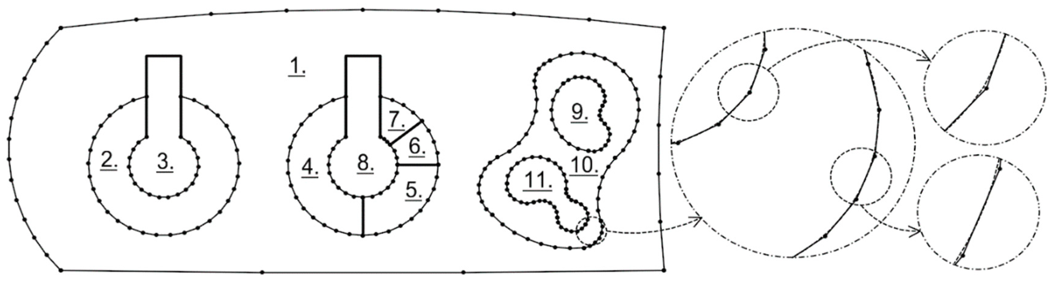
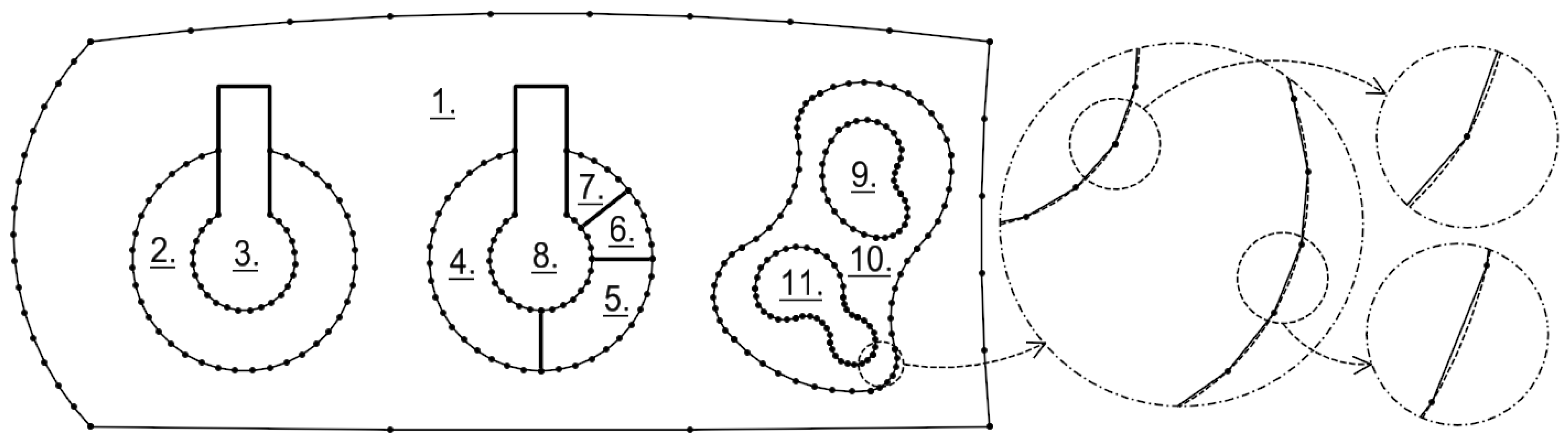
7. Algorithm Test
The algorithm test was performed on an example object containing various arc configurations (
Figure 8). As a deviation parameter,
dr = 0.14 m was assumed. Apart from comparing the results with the original areas and the circumferences of the parcels, a comparison was made with the previously used method of dividing the arc into equal chords.
Table 1 provides information on the division of each of the arches using the new method and the equal chords method. Compared to the proposed method and using the test object containing arcs of different radii (
Figure 9) the
Figure 10 and
Figure 11 show the density of arc points approximated by the new algorithm (
Figure 10) and by the chord algorithm (
Figure 11).
The presented solution (
Table 2) is very accurate. Note, however, that the calculations used coordinates in the “double precision” format. The area changes resulting from the rounding of the coordinates are shown in
Table 3. The new X, Y coordinates were rounded, respectively, to 1 mm, 1 cm and 1 dm. The results were not compared with the equal chords method because of the errors resulting from the use of the method itself.
The precision of recording the X, Y coordinates of the new border point (approximated) depends directly on the precision of the recording of the calculated length
d (7). For example, for the assumed data:
The following length value (7) in the “double precision” format is obtained:
By putting this data (10, 11) into the equation for the area of the circle segment with the approximated arc [
11]:
To answer the question of how the rounding of the length
d (11) with the precision of
μd (13) will affect the area, the law of propagation of errors [
18] should be applied to equation (12):
where
μA—area error caused by rounding
μd; ∂—symbol of the partial derivative.
For example, for rounding values 1 mm, 1 cm, 1 dm, the predicted errors
μA of the area are obtained, which confirm the results of the empirical test (
Table 3):
μd = 0.001 m → μA = 0.0102 m2;
μd = 0.01 m → μA = 0.1018 m2;
μd = 0.1 m → μA = 1.0175 m2.
The tests conducted show that the proposed algorithm is the right solution for cadastral purposes. In addition, there was a decrease in the number of border points in comparison to the previous approach (equal chords)—for the tested object, this reduction was equal to 12%. This is a very positive effect resulting from the application of the described algorithm. Comparing
Figure 9 and
Figure 10, it is also possible to find a better fit of the approximated polygon to the original arcs. Provisions concerning the admissible descriptive attributes of border points would require adjustment. The authors suggest adding an additional attribute to indicate the source of this type of point—in this case, “points from arc approximation”.
8. Conclusions
The solution suggested by the authors is a proposal that can contribute to solving the problem of arches in cadastral systems. These issues are related not only to cadastral systems in Europe, which were the inspiration for this work. Instead, the problem is wider and also concerns other countries [
19].
According to the authors, the optimum solution would be to save the coordinates of the calculated points in the “double precision” format. In addition, such points should have inserted the source information (status), e.g., points computed within the approximation of circular arcs.
It should be emphasised that the method proposed by the authors may also indirectly contribute to the solution for problems of the use of other curves in cadastral systems. A large part of scientific research in the field of geometry involves converting arbitrary curves into arcs [
20,
21,
22,
23]. With the two-step approach to this type of geometry, the final effect (preservation of parcel areas) may not be implemented in an exact way. However, the obtained results may be taken into account when developing technology for converting any curves into linear segments in cadastral systems.
In the existing cadastral systems in Europe (and in the world), solutions other than those proposed in this work can be used. Due to different technical and legal regulations in force in individual countries, we see the need to expand the scope of research on ways to describe circular arches. This problem will be the subject of further scientific research by the authors.
Author Contributions
Conceptualization, Mariusz Zygmunt; Formal analysis, Mariusz Zygmunt and Tadeusz Gargula; Methodology, Mariusz Zygmunt, Tadeusz Gargula and Przemysław Klapa; Project administration, Mariusz Zygmunt and Przemysław Klapa; Resources, Mariusz Zygmunt; Software, Mariusz Zygmunt; Supervision, Mariusz Zygmunt, Tadeusz Gargula and Przemysław Klapa; Validation, Mariusz Zygmunt; Visualization, Mariusz Zygmunt; Writing – original draft, Mariusz Zygmunt, Tadeusz Gargula and Przemysław Klapa; Writing – review & editing, Mariusz Zygmunt, Tadeusz Gargula and Przemysław Klapa. All authors have read and agreed to the published version of the manuscript.
Funding
This research received no external funding.
Conflicts of Interest
The authors declare no conflict of interest.
References
- Kudas, D.; Wnęk, A. Simulation of polygon area determination using GPS single frequency code receivers—Case study. Comput. Electron. Agric. 2019, 158, 92–101. [Google Scholar] [CrossRef]
- Imai, H.; Iri, M. Computational-geometric methods for polygonal approximations of a curve. Comput. Vis. Image Process. 1968, 36, 31–41. [Google Scholar] [CrossRef]
- Perez, J.C.; Vidal, E. An algorithm for the optimum piecewise linear approximation of digitized curves. In Proceedings of the 11th IAPR International Conference on Pattern Recognition, The Hague, The Netherlands, 30 August–1 September 1992; pp. 167–170. [Google Scholar]
- Gribov, A.; Bodansky, E. A new method of polyline approximation. In Structural, Syntactic, and Statistical Pattern Recognition; LNCS; Springer: Berlin/Heidelberg, Germany, 2004; pp. 504–511. [Google Scholar]
- Kolesnikov, A. Constrained Piecewise Linear Approximation of digital curves. In Proceedings of the 2008 19th International Conference on Pattern Recognition, ICPR’08, Tampa, FL, USA, 8–11 December 2008. [Google Scholar]
- Rosin, P. Techniques for assessing polygonal approximations of curves. IEEE Trans. Pattern Anal. Mach. Intell. 1997, 14, 659–666. [Google Scholar] [CrossRef]
- ORACLE Help Center. Spatial Developer’s Guide. Available online: https://docs.oracle.com/cd/B28359_01/appdev.111/b28400/sdo_objgeom.htm#i867636 (accessed on 6 April 2018).
- ESRI. Technical Article, Technical Support, Problem: Circular Arcs are Converted to Densified Lines. Available online: http://support.esri.com/technical-article/000003577 (accessed on 11 May 2018).
- Lai, L. “Where to draw the line?” That is a land use planning question for the land surveyor and the town planner. Land Use Policy 2015, 42, 619–627. [Google Scholar] [CrossRef][Green Version]
- Waldhaeusl, P.; Koenig, H.; Mansberger, R. Boundaries and Boundary Marks Substantive Cultural Heritage of Extensive Importance. ISPRS Ann. Photogramm. Remote Sens. Spat. Inf. Sci. 2015, II-5/W3, 329–334. [Google Scholar] [CrossRef]
- Zygmunt, M. Circular arc approximation using polygons. J. Comput. Appl. Math. 2017, 322, 81–85. [Google Scholar] [CrossRef]
- ISO 19152:2012. Geographic Information-Land Administration Domain Model (LADM); ISO: International Organization for Standardization: Geneva, Switzerland, 2012. [Google Scholar]
- Sladić, D.; Radulović, A.; Govedarica, M.; Jovanović, D.; Pržulj, D. The Use of Ontologies in Cadastral Systems. Comput. Sci. Inf. Syst. 2015, 12, 1033–1053. [Google Scholar] [CrossRef]
- INSPIRE D2.8.I.6. Data Specification on Cadastral Parcels-Technical Guidelines. Available online: https://inspire.ec.europa.eu/id/document/tg/cp (accessed on 20 November 2019).
- INSPIRE. Available online: http://inspire.ec.europa.eu (accessed on 24 April 2018).
- PN-EN-ISO 19125-1. Geographic Information-Simple Feature Access, Part 1: Common Architecture; Polish Committee for Standardization: Warsaw, Poland, 2006.
- ISO 19107:2003. Geographic Information—Spatial Schema; ISO: International Organization for Standardization: Geneva, Switzerland, 2003.
- Ghilani, C.D. Adjustment Computations: Spatial Data Analysis; John Wiley & Sons. Inc.: Hoboken, NJ, USA, 2010. [Google Scholar]
- Interpretation Guide to Rules for Cadastral Survey; LINZG65700 (6 December 2011); New Zealand Government, Office of the Surveyor-General, Land Information New Zealand: Wellington, New Zealand, 2010.
- Walton, D.J.; Meek, D.S. Approximation of a planar cubic Bezier spiral by circular arcs. J. Comput. Appl. Math. 1996, 75, 47–56. [Google Scholar] [CrossRef][Green Version]
- Hur, S.; Tae-wan, K. The best G1 cubic and G2 quartic Bézier approximations of circular arcs. J. Comput. Appl. Math. 2011, 236, 1183–1192. [Google Scholar] [CrossRef]
- Kaewsaiha, P.; Dejdumrong, N. Modeling of bézier cuves using a combination of linear and circular arc approximations. In Proceedings of the Ninth International Conference on Computer Graphics, Imaging and Visualization (CGIV), Hsinchu, Taiwan, 25–27 July 2012. [Google Scholar]
- Riškus, A. Approximation of a cubic Bézier curve by circular arcs and vice versa. Inf. Technol. Control. 2015, 35. [Google Scholar] [CrossRef]
© 2020 by the authors. Licensee MDPI, Basel, Switzerland. This article is an open access article distributed under the terms and conditions of the Creative Commons Attribution (CC BY) license (http://creativecommons.org/licenses/by/4.0/).


