A Low-Cost Collaborative Location Scheme with GNSS and RFID for the Internet of Things

 ,
,  ,
, 
Abstract
:1. Introduction
2. Related Works
2.1. Radio Frequency Identification (RFID)-Based Location
2.2. Low-Cost Location Scheme
2.3. Deployment Method and Pattern
3. Collaborative Scheme with Global Navigation Satellite System (GNSS) and RFID Location
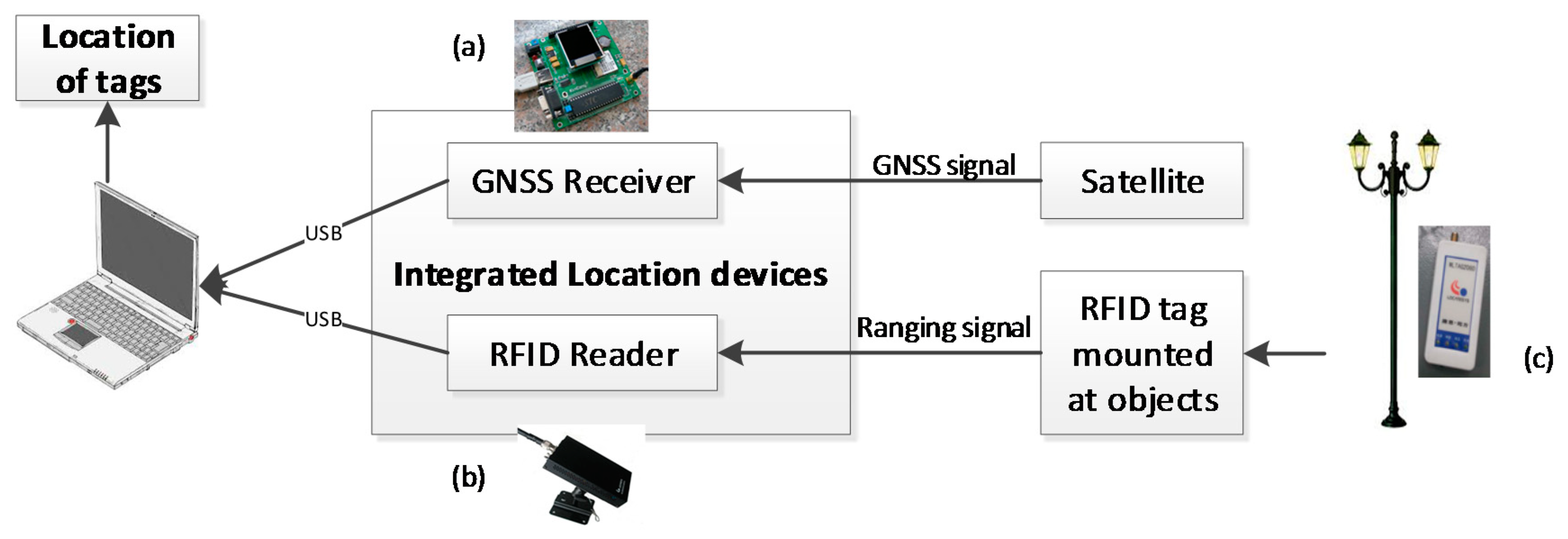
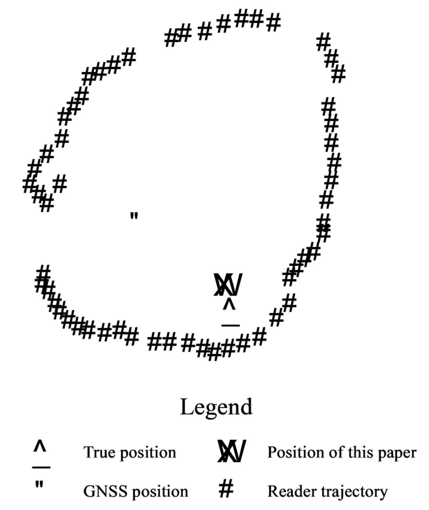
3.1. System Overview
- The RFID reader measures the distance (di) between the reader and the RFID tag attached to the target object when the RFID reader is moving, where i denotes the i-th location in RFID reader trajectory.
- The RFID reader position (pi) is measured by the GNSS receiver, which is expressed as (xi, yi) for the coordinate values.
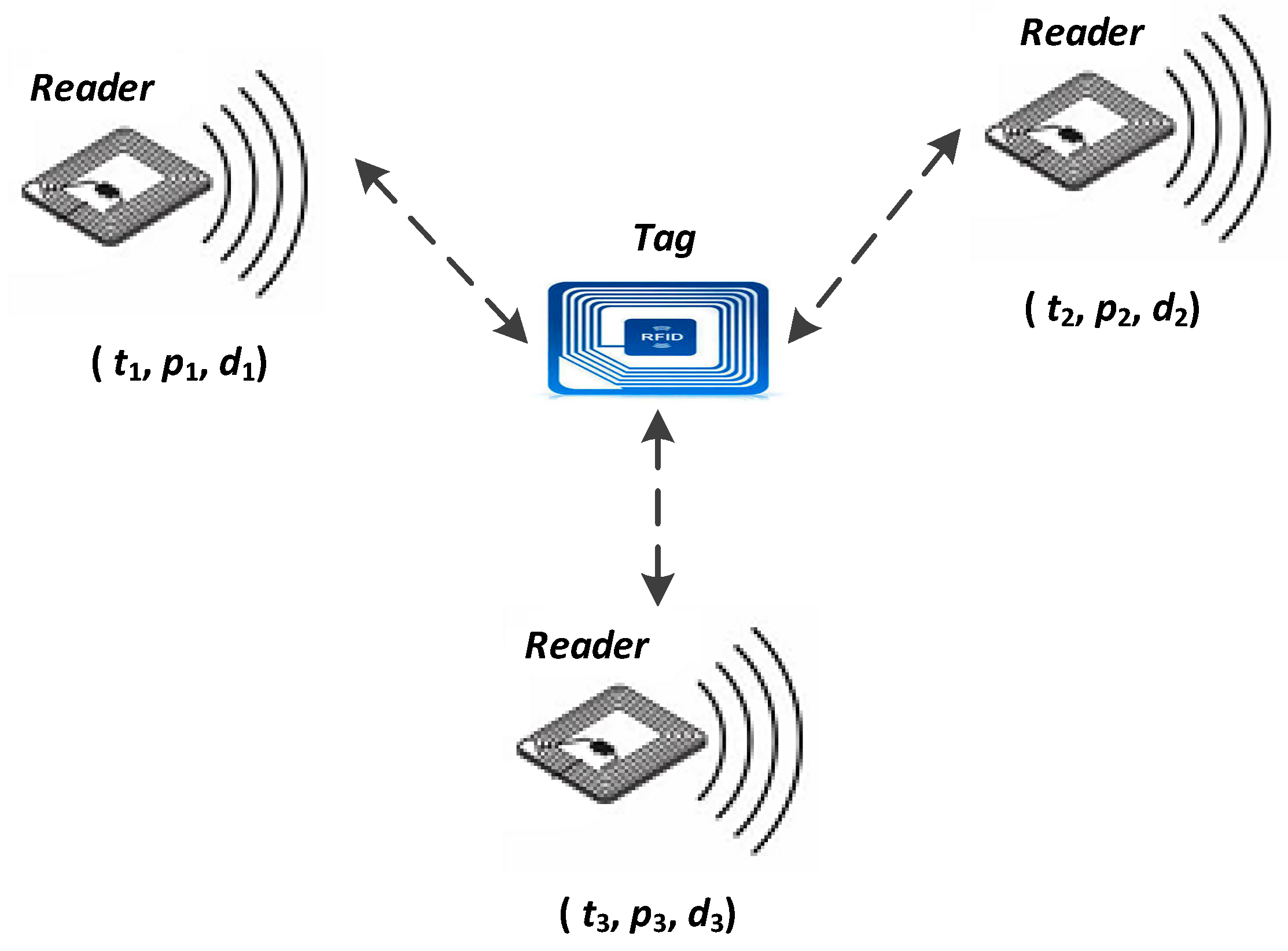
- When the RFID reader is moving, two tuples (pi, di) are ready. When three or more tuples are prepared, the exact location of the target tag can be estimated according to the method shown in the following section.
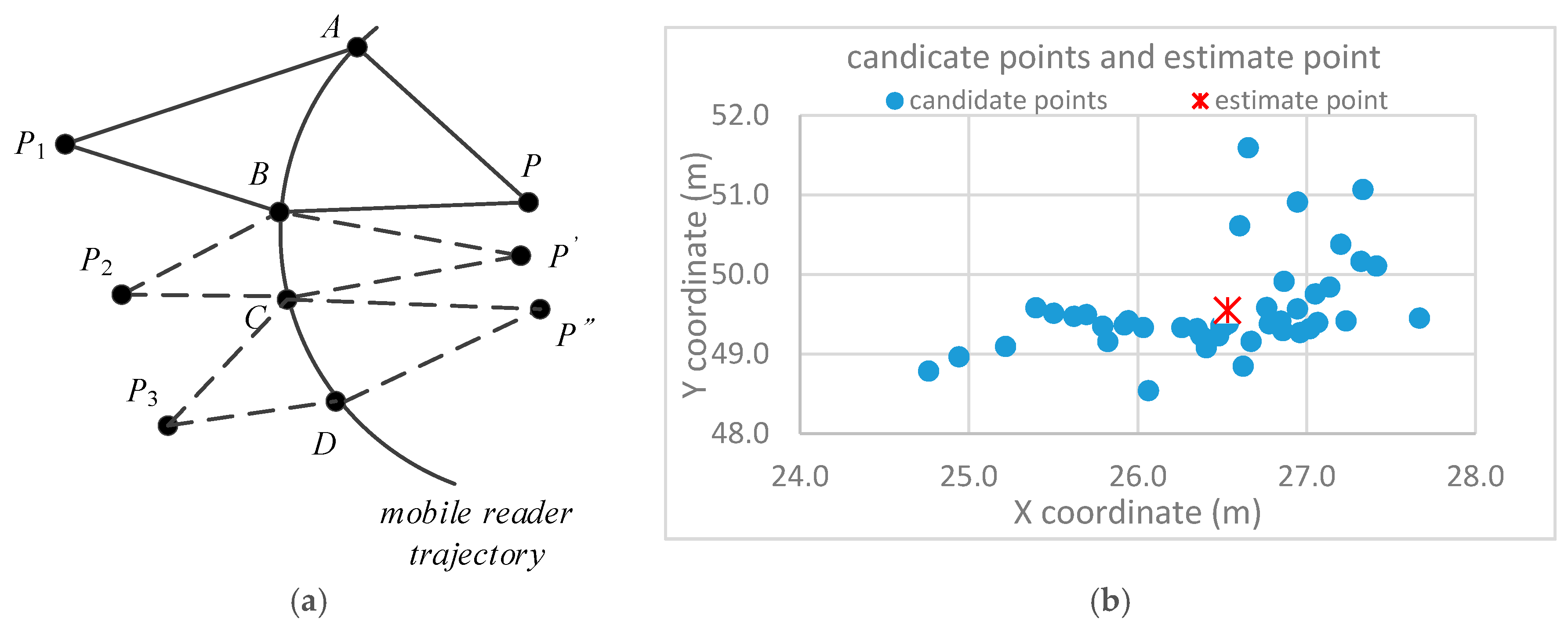
3.2. Tag-Location Principle
| Algorithm 1. Tag localization algorithm | |
| Input: reader location, distance Output: coordinate of target tag | |
| 1 | For each point in saved reader location points set do |
| 2 | set pi = point coordinate of points set |
| 3 | set pi+1 = reader location |
| 4 | set d1 = distance between pi and tag |
| 5 | set d2 = distance between pi and pi+1 |
| 6 | set d3 = distance between pi+1 and tag |
| 7 | if (pi, pi+1, d1, d2, d3) can build a triangle then |
| 8 | calculate the coordinate of target tag |
| 9 | add the coordinate to a candidate points set |
| 10 | else |
| 11 | continuous the next loop |
| 12 | end if |
| 13 | End for |
| 14 | Add (pi+1, d3) to reader location points set for next reader location calculate |
| 15 | For each coordinate of candidate points set do |
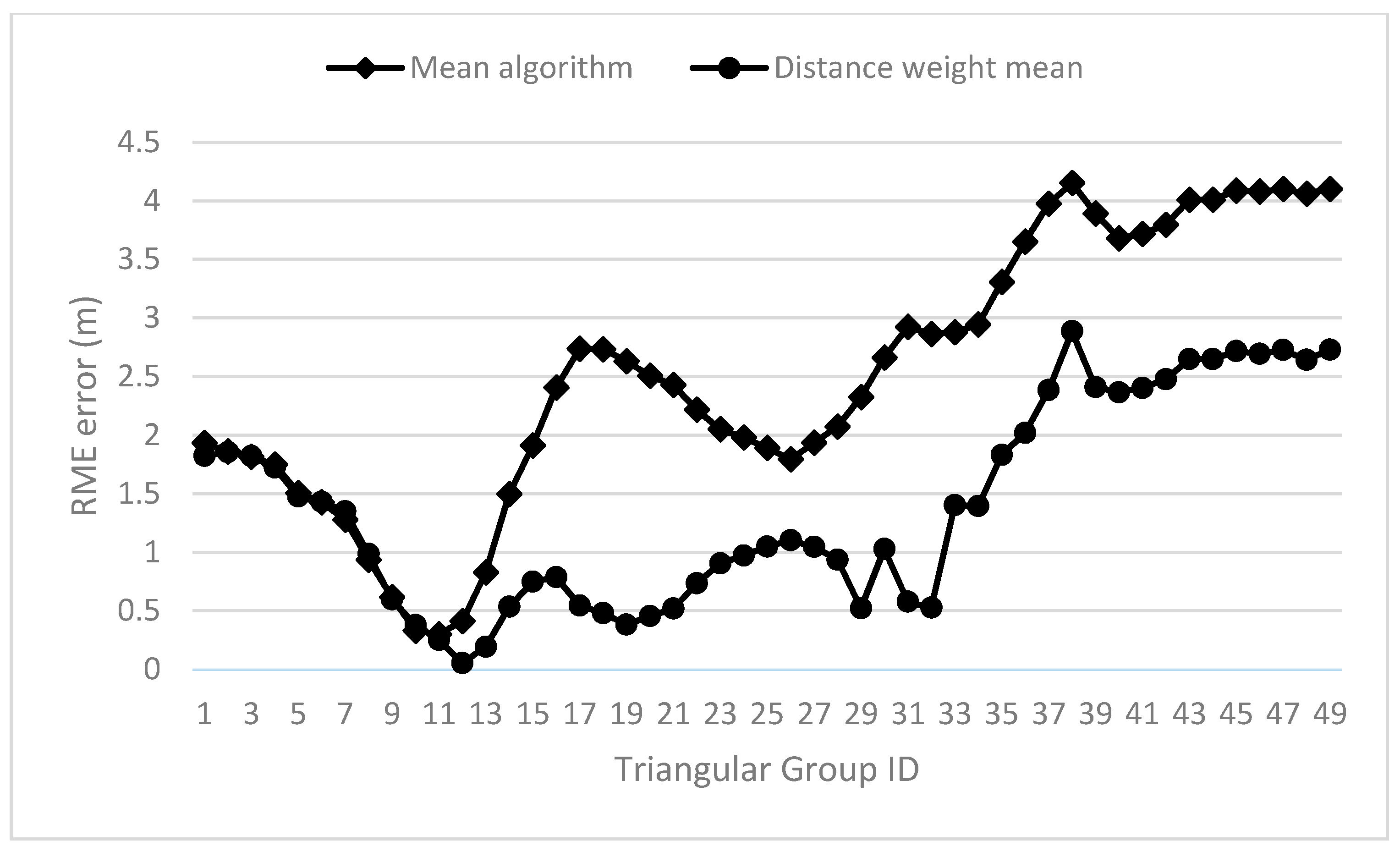
| 16 | Calculate the mean value of all points |
| 17 | End for |
3.3. Optimization
| Algorithm 2. Linear interpolation algorithm for reader location | |
| Input: reader location, time, distance detection times array Output: synchronous reader location array | |
| 1 | Set ps = reader location started, ts = start time |
| 2 | Set pd = reader location ended, td = end time |
| 3 | # find the closest time from the distance points |
| 4 | Set deltaTstart = t0 − ts, iIndexStart = 0 |
| 5 | Set deltaTend = td − t0, iIndexEnd = 0 |
| 6 | For each time ti of distance detection times array do |
| 7 | if ti − ts < deltaTstart then |
| 8 | set deltaTstart = ti − ts |
| 9 | set iIndexStart = i |
| 10 | end if |
| 11 | if td − ti < deltaTend then |
| 12 | set deltaTend = td − ti |
| 13 | set iIndexEnd = i |
| 14 | end if |
| 15 | End for |
| 16 | # Calculate the synchronous points |
| 17 | For each time ti of distance detection times array do |
| 18 | pi = ps + (ti − ts)/(td − ts) × (pd − ps) |
| 19 | add pi to synchronous reader location array |
| 20 | End for |
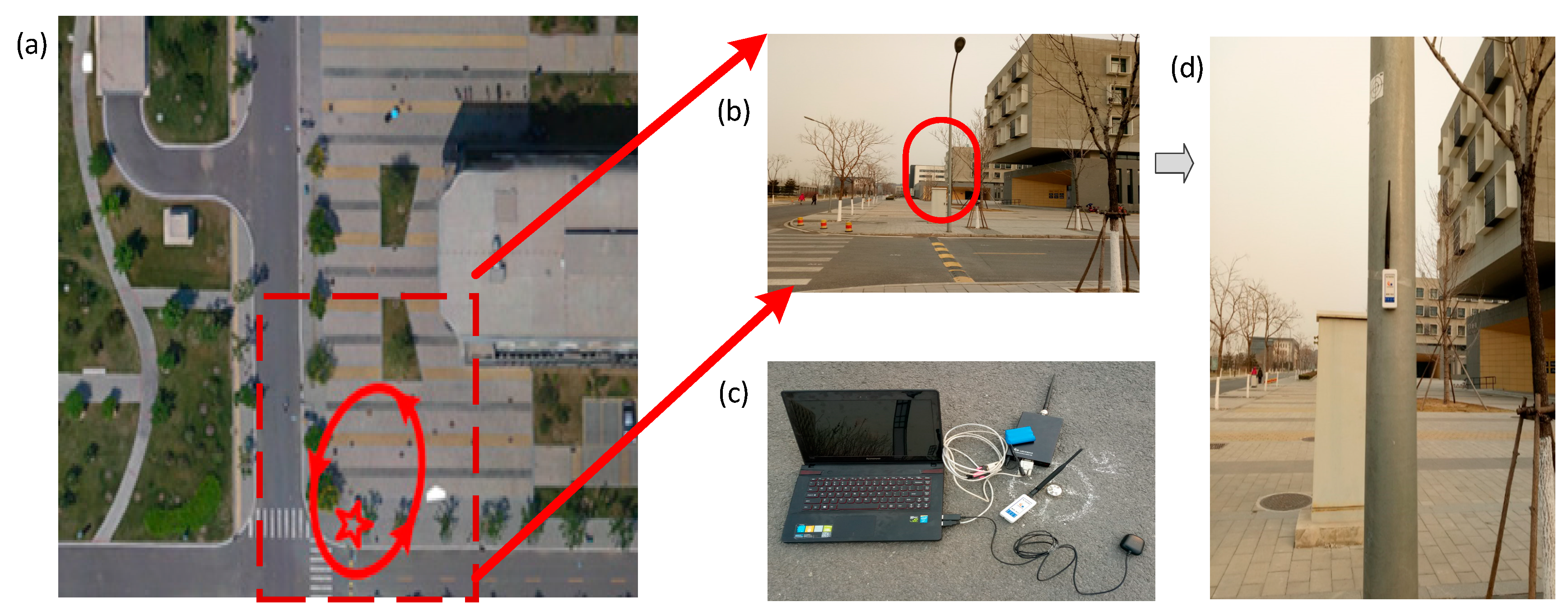
4. Experiment and Result
5. Discussion
5.1. Low-Cost and Easy Deployment
5.2. Location Determination Methods
6. Conclusions
Author Contributions
Funding
Acknowledgments
Conflicts of Interest
References
- Atzori, L.; Iera, A.; Morabito, G. The internet of things: A survey. Comput. Netw. 2010, 54, 2787–2805. [Google Scholar] [CrossRef]
- Alletto, S.; Cucchiara, R.; Del Fiore, G.; Mainetti, L.; Mighali, V.; Patrono, L.; Serra, G. An Indoor Location-Aware System for an IoT-Based Smart Museum. IEEEE Internet Things 2016, 3, 244–253. [Google Scholar] [CrossRef]
- Hoang, V.-D.; Le, M.-H.; Tran, T.T.; Pham, V.-H. Improving Traffic Signs Recognition Based Region Proposal and Deep Neural Networks. In Intelligent Information and Database Systems; Springer: Cham, Germany, 2018; pp. 604–613. [Google Scholar]
- Tao, C.V. Mobile mapping technology for road network data acquisition. J. Geospat. Eng. 2000, 2, 1–14. [Google Scholar]
- Bean, E.Z.; Hunt, W.F.; Bidelspach, D.A. Field Survey of Permeable Pavement Surface Infiltration Rates. J. Irrig. Drain. Eng. 2007, 133, 249–255. [Google Scholar] [CrossRef]
- Yu, Y.; Li, J.; Guan, H.; Wang, C.; Yu, J. Semiautomated Extraction of Street Light Poles From Mobile LiDAR Point-Clouds. IEEE Trans. Geosci. Remote Sens. 2015, 53, 1374–1386. [Google Scholar] [CrossRef]
- Monnier, F.; Vallet, B.; Soheilian, B. Trees Detection from Laser Point Clouds Acquired in Dense Urban Areas by a Mobile Mapping System. ISPRS Ann. Photogramm. Remote Sens. Spat. Inf. Sci. 2012, I-3, 245–250. [Google Scholar] [CrossRef]
- Zhang, D.; Yang, L.T.; Chen, M.; Zhao, S.; Guo, M.; Zhang, Y. Real-Time Locating Systems Using Active RFID for Internet of Things. IEEE Syst. J. 2014, 10, 1–10. [Google Scholar] [CrossRef]
- Matarazzo, T.; Vazifeh, M.; Pakzad, S.; Santi, P.; Ratti, C. Smartphone data streams for bridge health monitoring. Procedia Eng. 2017, 199, 966–971. [Google Scholar] [CrossRef]
- Jayawardana, D.; Kharkovsky, S.; Liyanapathirana, R.; Zhu, X. Measurement System With Accelerometer Integrated RFID Tag for Infrastructure Health Monitoring. IEEE Trans. Instrum. Meas. 2016, 65, 1163–1171. [Google Scholar] [CrossRef]
- Lin, K.; Chen, M.; Deng, J.; Hassan, M.M.; Fortino, G. Enhanced Fingerprinting and Trajectory Prediction for IoT Localization in Smart Buildings. IEEE Trans. Autom. Sci. Eng. 2016, 13, 1294–1307. [Google Scholar] [CrossRef]
- Maneesilp, J.; Wang, C.; Wu, H.; Tzeng, N.F. RFID Support for Accurate 3D Localization. IEEE Trans. Comput. 2013, 62, 1447–1459. [Google Scholar] [CrossRef]
- Azzouzi, S.; Cremer, M.; Dettmar, U.; Knie, T.; Kronberger, R. Improved AoA based localization of UHF RFID tags using spatial diversity. In Proceedings of the 2011 IEEE International Conference on RFID-Technologies and Applications, Sitges, Spain, 15–16 September 2011; IEEE: Piscataway, NJ, USA, 2011; pp. 174–180. [Google Scholar]
- Stelzer, A.; Pourvoyeur, K.; Fischer, A. Concept and Application of LPM—A Novel 3-D Local Position Measurement System. IEEE Trans. Microw. Theory Tech. 2004, 52, 2664–2669. [Google Scholar] [CrossRef]
- Abreu, P.H.; Xavier, J.; Castro Silva, D.; Reis, L.P.; Petry, M. Using Kalman filters to reduce noise from RFID location system. Sci. World J. 2014, 2014, 1–10. [Google Scholar] [CrossRef] [PubMed]
- Hightower, J.; Borriello, G.; Want, R. SpotON: An Indoor 3D Location Sensing Technology Based on RF Signal Strength; University of Washington: Seattle, WA, USA, 2000. [Google Scholar]
- Zhou, C.; Griffin, J.D. Accurate Phase-Based Ranging Measurements for Backscatter RFID Tags. IEEE Antennas Wirel. Propag. Lett. 2012, 11, 152–155. [Google Scholar] [CrossRef]
- Bekkali, A.; Sanson, H.; Matsumoto, M. RFID indoor positioning based on probabilistic RFID map and Kalman Filtering. In Proceedings of the 3rd IEEE International Conference on Wireless and Mobile Computing, Networking and Communications, WiMob 2007, White Plains, NY, USA, 8–10 October 2007; IEEE: Piscataway, NJ, USA, 2007. [Google Scholar]
- Cheng, C.-Y. Indoor localization algorithm using clustering on signal and coordination pattern. Ann. Oper. Res. 2014, 216, 83–99. [Google Scholar] [CrossRef]
- Deng, Z.; Yu, Y.; Yuan, X.; Wan, N.; Yang, L. Situation and development tendency of indoor positioning. China Commun. 2013, 10, 42–55. [Google Scholar] [CrossRef]
- Chai, J.; Wu, C.; Zhao, C.; Chi, H.L.; Wang, X.; Ling, B.W.K.; Teo, K.L. Reference tag supported RFID tracking using robust support vector regression and Kalman filter. Adv. Eng. Inform. 2017, 32, 1–10. [Google Scholar] [CrossRef]
- Wang, C.; Wu, H.; Tzeng, N.-F. RFID-Based 3-D Positioning Schemes. In Proceedings of the IEEE INFOCOM 2007—26th IEEE International Conference on Computer Communications, Barcelona, Spain, 6–12 May 2007; IEEE: Piscataway, NJ, USA, 2007; pp. 1235–1243. [Google Scholar]
- Ni, L.M.; Liu, Y.; Lau, Y.C.; Patil, A.P. LANDMARC: Indoor Location Sensing Using Active RFID. Wirel. Netw. 2004, 10, 701–710. [Google Scholar] [CrossRef]
- Bulusu, N.; Heidemann, J.; Estrin, D. GPS-less low-cost outdoor localization for very small devices. IEEE Pers. Commun. 2000, 7, 28–34. [Google Scholar] [CrossRef]
- Shirehjini, A.A.N.; Yassine, A.; Shirmohammadi, S. Equipment Location in Hospitals Using RFID-Based Positioning System. IEEE Trans. Inf. Technol. Biomed. 2012, 16, 1058–1069. [Google Scholar] [CrossRef] [PubMed]
- Son, Y.; Joung, M.H.; Lee, Y.W.; Kwon, O.H.; Song, H.J. Tag localization in a two-dimensional RFID tag matrix. Future Gener. Comput. Syst. 2017, 76, 384–390. [Google Scholar] [CrossRef]
- Liu, X.; Shannon, J.; Voun, H.; Truijens, M.; Chi, H.-L.; Wang, X. Spatial and Temporal Analysis on the Distribution of Active Radio-Frequency Identification (RFID) Tracking Accuracy with the Kriging Method. Sensors 2014, 14, 20451–20467. [Google Scholar] [CrossRef] [PubMed]
- Huang, S.; Guo, Y.; Zha, S.; Wang, F.; Fang, W. A Real-time Location System Based on RFID and UWB for Digital Manufacturing Workshop. Procedia CIRP 2017, 63, 132–137. [Google Scholar] [CrossRef]
- Ang, L.-M.; Seng, K.P.; Zungeru, A.; Ijemaru, G. Big Sensor Data Systems for Smart Cities. IEEE Internet Things J. 2017, 4, 1259–1272. [Google Scholar] [CrossRef]
- Bouchard, K.; Fortin-Simard, D.; Gaboury, S.; Bouchard, B.; Bouzouane, A. Accurate RFID trilateration to learn and recognize spatial activities in smart environment. Int. J. Distrib. Sens. Netw. 2013, 2013. [Google Scholar] [CrossRef]
- Motamedi, A.; Soltani, M.M.; Hammad, A. Localization of RFID-equipped assets during the operation phase of facilities. Adv. Eng. Inform. 2013, 27, 566–579. [Google Scholar] [CrossRef]
- Geetha, E. A bayesian inference-based framework for RFID data cleansing. J. Nanosci. Nanotechnol. 2014, 2, 296–304. [Google Scholar] [CrossRef]
- Prinsloo, J.; Malekian, R. Accurate vehicle location system using RFID, an internet of things approach. Sensors 2016, 16, 825. [Google Scholar] [CrossRef] [PubMed]
- Lee, D.; Cho, J.; Suh, Y.; Hwang, J.; Yun, H. A new window-based program for quality control of GPS sensing data. Remote Sens. 2012, 4, 3168–3183. [Google Scholar] [CrossRef]
- Ding, X.; Coleman, R. Multiple outlier detection by evaluating redundancy contributions of observations. J. Geod. 1996, 70, 489–498. [Google Scholar] [CrossRef]
- Zhao, J.; Zhao, Q.; Li, Z.; Liu, Y. An improved Weighted Centroid Localization algorithm based on difference of estimated distances for Wireless Sensor Networks. Telecommun. Syst. 2013, 53, 25–31. [Google Scholar] [CrossRef]
- Saab, S.S.; Msheik, H. Novel RFID-Based Pose Estimation Using Single Stationary Antenna. IEEE Trans. Ind. Electron. 2016, 63, 1842–1852. [Google Scholar] [CrossRef]
- Jin, J.; Gubbi, J.; Marusic, S.; Palaniswami, M. An Information Framework for Creating a Smart City Through Internet of Things. IEEE Internet Things J. 2016, 1, 112–121. [Google Scholar] [CrossRef]
- Rathore, M.M.; Ahmad, A.; Paul, A.; Rho, S. Urban planning and building smart cities based on the Internet of Things using Big Data analytics. Comput. Netw. 2016, 101, 63–80. [Google Scholar] [CrossRef]
- Gartner Gartner Report: 6.4 Billion Connected Things Will Be in Use in 2016, Up 30 Percent From 2015. Available online: https://www.gartner.com/newsroom/id/3165317 (accessed on 31 January 2018).
- Retscher, G. An Intelligent Personal Navigator Integrating GNSS, RFID and INS; Springer: Berlin/Heidelberg, Germany, 2012; pp. 949–955. [Google Scholar]
- Soltani, M.M. Neighborhood Localization Method for Locating Construction Resources Based on RFID and BIM; Concordia University: Montréal, QC, Canada, 2013. [Google Scholar]
- Zhao, Y.; Liu, Y.; Ni, L.M. VIRE: Active RFID-based Localization Using Virtual Reference Elimination. In Proceedings of the 2007 International Conference on Parallel Processing (ICPP 2007), Xi’an, China, 10–14 Septenber 2007; IEEE: Piscataway, NJ, USA, 2007; p. 56. [Google Scholar]
- Sue, K.-L.; Tsai, C.-H.; Lin, M.-H. FLEXOR: A Flexible Localization Scheme Based on RFID. In Information Networking. Advances in Data Communications and Wireless Networks; Springer: Berlin/Heidelberg, Germany, 2006; pp. 306–316. [Google Scholar]
- Huang, Y.; Lv, S.; Liu, Z.; Jun, W.; Jun, S. The topology analysis of reference tags of RFID indoor location system. In Proceedings of the 2009 3rd IEEE International Conference on Digital Ecosystems and Technologies, DEST ’09, Istanbul, France, 1–3 June 2009; IEEE: Piscataway, NJ, USA, 2009; pp. 313–317. [Google Scholar]
- Li, W.; Wu, J.; Wang, D. A novel indoor positioning method based on key reference RFID tags. In Proceedings of the 2009 IEEE Youth Conference on Information, Computing and Telecommunication, Beijing, China, 20–21 September 2009; pp. 42–45. [Google Scholar] [CrossRef]
- Kaemarungsi, K.; Ranron, R.; Pongsoon, P. Study of received signal strength indication in ZigBee location cluster for indoor localization. In Proceedings of the 2013 10th International Conference on Electrical Engineering/Electronics, Computer, Telecommunications and Information Technology, ECTI-CON 2013, Krabi, Thailand, 15–17 May 2013; IEEE: Krabi, Thailand, 2013; pp. 1–6. [Google Scholar]
- Shikada, M.; Shiraishi, S.; Takeuchi, S. The Method To Obtain Position Using Gnss And Rfid For Realization Of Indoor And Outdoor Seamless Positioning. ISPRS Int. Arch. Photogramm. Remote Sens. Spat. Inf. Sci. 2012, XXXIX-B4, 45–50. [Google Scholar] [CrossRef]
- Cai, H.; Andoh, A.R.; Su, X.; Li, S. A boundary condition based algorithm for locating construction site objects using RFID and GPS. Adv. Eng. Inform. 2014, 28, 455–468. [Google Scholar] [CrossRef]
- Arebey, M.; Hannan, M.A.; Basri, H.; Begum, R.A.; Abdullah, H. Solid waste monitoring system integration based on RFID, GPS and camera. In Proceedings of the 2010 International Conference on Intelligent and Advanced Systems, Kuala Lumpur, Malaysia, 15–17 June 2010; pp. 1–5. [Google Scholar] [CrossRef]
- Viani, F.; Salucci, M.; Robol, F.; Oliveri, G.; Massa, A. Design of a UHF RFID/GPS Fractal Antenna for Logistics Management. J. Electromagn. Waves Appl. 2012, 26, 480–492. [Google Scholar] [CrossRef]
- Li, J.; Gao, J.; Zhang, H.; Qiu, T.Z. A RSE-Assisted GPS-RSS Hybrid Lane-Level Positioning System for Connected Vehicles. In Proceedings of the Transportation Research Board 95th Annual Meeting, Washington, DC, USA, 10–14 January 2016; pp. 1–17. [Google Scholar]
- Wu, B.; Chen, Y.; Huang, P. A Localization-Assistance System using GPS and Wireless Sensor Networks for Pedestrian Navigation. J. Converg. Inf. Technol. 2012, 7, 146–155. [Google Scholar] [CrossRef]
- Xue, R.; Wang, Z.; Zhu, Y. Upper bound estimation of positioning error for ground-based augmentation system. GPS Solut. 2017, 21, 1781–1790. [Google Scholar] [CrossRef]
- Singh, A.; Chu, C.H.; Pratt, M.A. Saliency Detection using Geometric Context Contrast Inferred from Natural Images. In Proceedings of the 10th International Conference on Computer Vision Theory and Applications, Berlin, Germany, 11–14 March 2015; pp. 609–616. [Google Scholar] [CrossRef]
- Huang, Y.; Shekhar, S.; Xiong, H. Discovering colocation patterns from spatial data sets: A general approach. IEEE Trans. Knowl. Data Eng. 2004, 16, 1472–1485. [Google Scholar] [CrossRef]
- Sabesan, S.; Crisp, M.J.; Penty, R.V.; White, L.H. RFID Tag Location Systems. U.S. Patent 9367785B2, 26 April 2010. [Google Scholar]
- Cui, D.; Zhang, Q. The RFID data clustering algorithm for improving indoor network positioning based on LANDMARC technology. Clust. Comput. 2017. [Google Scholar] [CrossRef]


| Triangle Group ID | Triangle Number | xc (m) | yc (m) | Root Mean Error (m) | Triangle Group ID | Triangle Number | xc (m) | yc (m) | Root Mean Error (m) |
|---|---|---|---|---|---|---|---|---|---|
| b1 | 15 | 494,125.50 | 286,449.52 | 1.8215 | b26 | 184 | 494,126.21 | 286,449.35 | 1.1016 |
| b2 | 24 | 494,125.47 | 286,449.52 | 1.8545 | b27 | 258 | 494,126.27 | 286,449.40 | 1.0447 |
| b3 | 24 | 494,125.51 | 286,449.51 | 1.8205 | b28 | 192 | 494,126.39 | 286,449.44 | 0.9349 |
| b4 | 42 | 494,125.60 | 286,449.49 | 1.7216 | b29 | 259 | 494,126.96 | 286,449.68 | 0.5216 |
| b5 | 78 | 494,125.84 | 286,449.37 | 1.4762 | b30 | 174 | 494,127.61 | 286,450.28 | 1.0269 |
| b6 | 67 | 494,125.88 | 286,449.32 | 1.4303 | b31 | 112 | 494,127.03 | 286,449.79 | 0.5772 |
| b7 | 93 | 494,125.96 | 286,449.29 | 1.3482 | b32 | 200 | 494,126.97 | 286,449.69 | 0.5259 |
| b8 | 96 | 494,126.33 | 286,449.20 | 0.9850 | b33 | 246 | 494,127.70 | 286,450.64 | 1.4010 |
| b9 | 28 | 494,126.72 | 286,449.26 | 0.5963 | b34 | 203 | 494,127.63 | 286,450.65 | 1.3932 |
| b10 | 84 | 494,126.93 | 286,449.27 | 0.3788 | b35 | 173 | 494,127.74 | 286,451.07 | 1.8299 |
| b11 | 140 | 494,127.06 | 286,449.28 | 0.2500 | b36 | 268 | 494,127.60 | 286,451.29 | 2.0181 |
| b12 | 144 | 494,127.27 | 286,449.32 | 0.0532 | b37 | 205 | 494,127.66 | 286,451.65 | 2.3832 |
| b13 | 108 | 494,127.48 | 286,449.38 | 0.1929 | b38 | 73 | 494,127.99 | 286,452.10 | 2.8866 |
| b14 | 129 | 494,127.80 | 286,449.52 | 0.5338 | b39 | 293 | 494,127.84 | 286,451.64 | 2.4099 |
| b15 | 37 | 494,127.98 | 286,449.62 | 0.7472 | b40 | 184 | 494,128.07 | 286,451.53 | 2.3650 |
| b16 | 72 | 494,127.97 | 286,449.73 | 0.7879 | b41 | 482 | 494,128.07 | 286,451.57 | 2.4019 |
| b17 | 74 | 494,127.58 | 286,449.77 | 0.5453 | b42 | 93 | 494,128.05 | 286,451.66 | 2.4760 |
| b18 | 156 | 494,127.48 | 286,449.74 | 0.4792 | b43 | 188 | 494,127.86 | 286,451.88 | 2.6478 |
| b19 | 86 | 494,127.22 | 286,449.66 | 0.3827 | b44 | 258 | 494,127.86 | 286,451.88 | 2.6478 |
| b20 | 40 | 494,126.96 | 286,449.58 | 0.4542 | b45 | 196 | 494,127.60 | 286,451.99 | 2.7157 |
| b21 | 86 | 494,126.86 | 286,449.54 | 0.5181 | b46 | 450 | 494,127.59 | 286,451.97 | 2.6938 |
| b22 | 86 | 494,126.60 | 286,449.46 | 0.7336 | b47 | 294 | 494,127.48 | 286,452.01 | 2.7256 |
| b23 | 92 | 494,126.41 | 286,449.41 | 0.9043 | b48 | 188 | 494,127.28 | 286,451.93 | 2.6417 |
| b24 | 123 | 494,126.35 | 286,449.39 | 0.9713 | b49 | 564 | 494,127.12 | 286,452.01 | 2.7276 |
| b25 | 46 | 494,126.27 | 286,449.37 | 1.0478 | - | - | - | - | - |
| Group number = 49; Average = 1.3904 m; maximum = 2.8866 m; minimum = 0.0532 m | |||||||||
© 2018 by the authors. Licensee MDPI, Basel, Switzerland. This article is an open access article distributed under the terms and conditions of the Creative Commons Attribution (CC BY) license (http://creativecommons.org/licenses/by/4.0/).
Share and Cite
Jing, C.; Wang, S.; Wang, M.; Du, M.; Zhou, L.; Sun, T.; Wang, J. A Low-Cost Collaborative Location Scheme with GNSS and RFID for the Internet of Things. ISPRS Int. J. Geo-Inf. 2018, 7, 180. https://doi.org/10.3390/ijgi7050180
Jing C, Wang S, Wang M, Du M, Zhou L, Sun T, Wang J. A Low-Cost Collaborative Location Scheme with GNSS and RFID for the Internet of Things. ISPRS International Journal of Geo-Information. 2018; 7(5):180. https://doi.org/10.3390/ijgi7050180
Chicago/Turabian StyleJing, Changfeng, Shouqing Wang, Mingshu Wang, Mingyi Du, Lei Zhou, Tiancheng Sun, and Jian Wang. 2018. "A Low-Cost Collaborative Location Scheme with GNSS and RFID for the Internet of Things" ISPRS International Journal of Geo-Information 7, no. 5: 180. https://doi.org/10.3390/ijgi7050180
APA StyleJing, C., Wang, S., Wang, M., Du, M., Zhou, L., Sun, T., & Wang, J. (2018). A Low-Cost Collaborative Location Scheme with GNSS and RFID for the Internet of Things. ISPRS International Journal of Geo-Information, 7(5), 180. https://doi.org/10.3390/ijgi7050180