Article

A Multiresolution Grid Structure Applied to Seafloor Shape Modeling

by
Wojciech Maleika
,
Michał Koziarski
and
Paweł Forczmański
*
Faculty of Computer Science and Information Technology, West Pomeranian University of Technology, Szczecin, Żołnierska Str. 52, 71-210 Szczecin, Poland
*
Author to whom correspondence should be addressed.
ISPRS Int. J. Geo-Inf. 2018, 7(3), 119; https://doi.org/10.3390/ijgi7030119
Submission received: 31 January 2018 / Revised: 27 February 2018 / Accepted: 14 March 2018 / Published: 16 March 2018

Abstract

:
This paper proposes a method of creating a multiresolution depth grid containing bathymetric data describing a stretch of sea floor. The included literature review presents current solutions in the area of the creation of digital terrain models (DTMs) focusing on methods employing regular grids, with a discussion on the strong and weak points of such an approach. As a basis for the investigations, some important recommendations from the International Hydrographic Organization are provided and are related to the accuracy of created models. The authors propose a novel method of storing DTM data, involving multiresolution depth grids. The paper presents the characteristics of this method, numerical algorithms of a conversion between a regular grid and the multiresolution one, and experiments on typical seafloor surfaces. The results are discussed, focusing on the data reduction rate and the variable resolution of the grid structure. The proposed method can be applied in Geographical Information Systems, especially for the purposes of solving sea survey problems.

1. Introduction

1.1. Introduction to the Multibeam Swath Bathymetry

Multibeam echosounders (MBESs) are widely used in marine environment surveillance, detailed bathymetry measurement and seafloor mapping, underwater object detection and imaging, or submerged infrastructure inspection. Current trends in their development involve the introduction of innovative transducer materials and the application of sophisticated processing techniques, including focusing algorithms that dynamically compensate for the curvature of the wavefront in the nearfield and thus allow for narrower beam widths (higher lateral resolution) at close ranges.
A “swath-sounding” echo system is one that is used to measure depth in a line extending outwards from the sounder transducer. Such a system acquires data at right angles in the direction of the motion of the transducer head. As the head moves forward, these profiles sweep out a ribbon-shaped surface of depth measurement, which is the so-called “swath.” Current swath sounding systems utilize two different technologies to achieve bathymetry measurements across a swath of a sea floor: (1) beam forming (MBESs) and (2) interferometric or phase discrimination (sonars). Both techniques have their advantages and disadvantages, but they lead to the same end results.
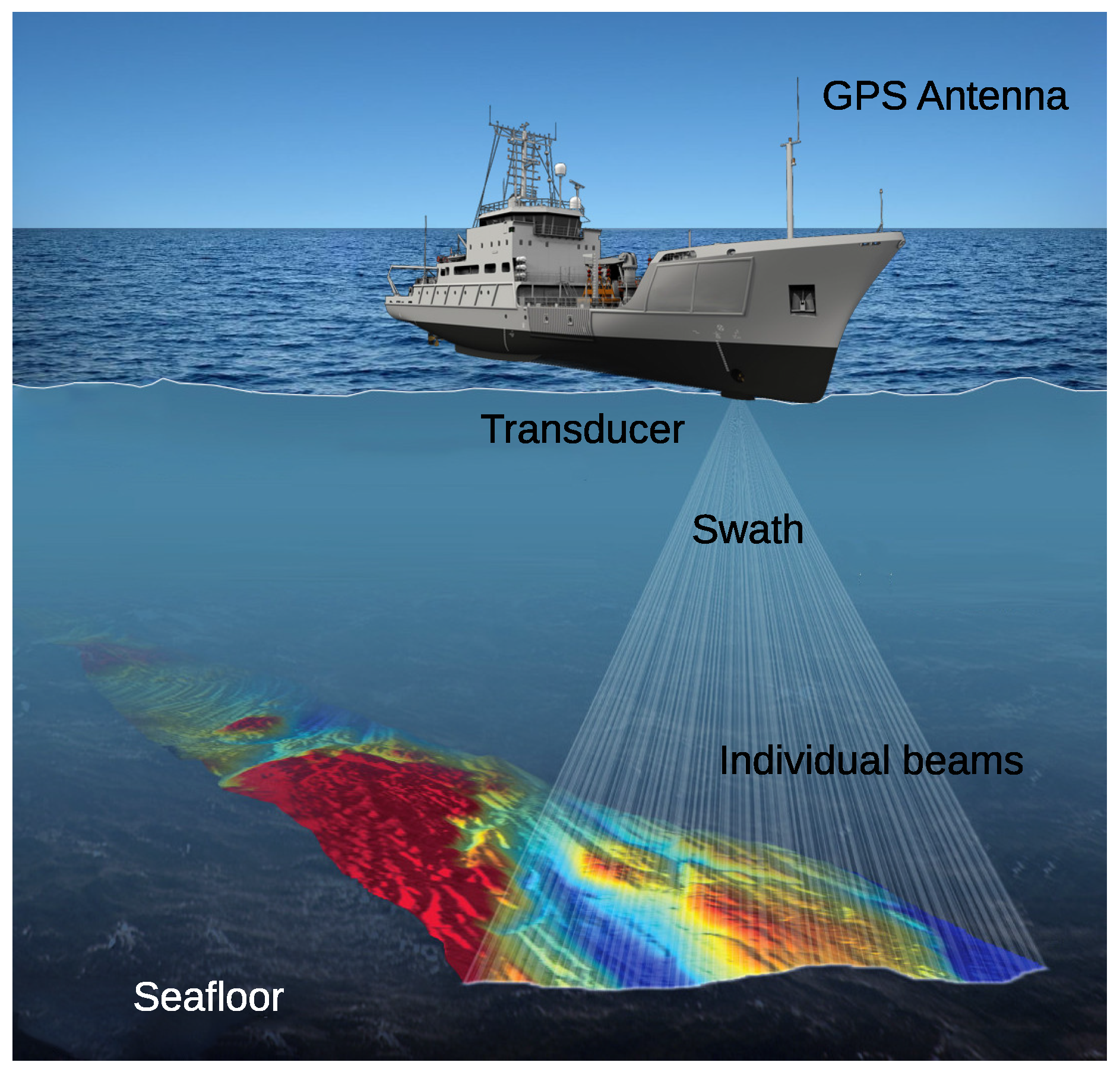
MBESs collect bathymetric soundings in a swath perpendicular to the ship track by electronically forming a series of transmit and receive beams in the transducer hardware, which measure the depth to the sea floor in discrete angular increments or sectors across the swath (see Figure 1).
Based on measurement data collected during sea surveys, digital terrain models (DTMs) are created using appropriate data processing algorithms. Created DTMs, and subsequently derived seabed maps, must fulfill the norms specified in Special Publication No. 44 issued by the International Hydrographical Organizationn (IHO) [2,3]. The fundamental aim of that document is to specify the minimal hydrographic survey norms, to assure that the measurement data is collected in accordance with them, and, as a consequence, to ensure the accuracy of created models and maps. These norms also enable users to determine the spatial uncertainty of the data, and effective utilization of them ensures the safe use of measurement results.
Taking into consideration a very large amount of data collected during the survey and the IHO requirements, a DTM is usually made on the basis of a grid structure (a regular net of squares) [4,5]. There are numerous methods of grid creation based on measurement data, the ones most often applied being kriging, a modified Shepard’s method, a radial basis function, the inverse distance to a power, triangulation with linear interpolation, moving average, wavelet methods [6], and others based on artificial intelligence [2].
In many practical hydrographic works, the native resolution of the grid structure is equal to one meter. It is easy to calculate because an area of one square kilometer described in this way contains one million points, stored on 3.8 or 7.6 MB (depending on the single precision floating-point representation, using 4 or 8 Bytes, respectively). Although mass storage devices make it possible to record an enormous amount of data, the other processes related to data transmission, retrieval, and processing are negatively influenced by their volume. Therefore, it is hard to imagine creating a model of a rather large area (a lake, bay, sea, or part of an ocean) with a high grid resolution. The volume of data in such a case seems to be beyond control.

1.2. Existing Methods

A number of approaches for mesh simplification and multiresolution surface triangulation have been developed over the last decades. Many general aspects of grids, multiresolution grids, nested grids, and all possible variations of quadtrees were presented by Samet [7]. Detailed overviews on general mesh simplification and multiresolution modeling were given by Heckbert and Garland [8], Cignoni et al. [9], and Luebke [10]. Gerstner [11] proposed a hierarchical decomposition of the sphere by a recursive bisection triangulation in geographic coordinates is presented. Unfortunately, the author applied this method to a Triangulated Irregular Network (TIN) model only. Ben-Moshe et al. [12] proposed a new terrain simplification algorithm based on several known digital image processing methods (e.g., DCT and wavelets compression), which were specially adjusted to fit digital elevation models (DEMs). The presented algorithm is based on the processing of integer numbers only (the elevation data are given as grayscale images), which may be not describe bathymetic data with sufficient accuracy. It should be noted that even TIFF-based formats such as GeoTIFF are limited with the accuracy of finite integer numbers. Hence, ASCII-based files, such as comma-separated values (csv) or ASCII-grid (txt) are more flexible. Parajola [13] proved that hierarchical quad-tree-based terrain triangulation model is among the most efficient methods available. This method is based on a regular grid of triangles, and the output model is stored in a quad-tree structure, which is not particularly suitable for direct processing. Lau et al. [14] presented a modified ODETLAP method for smoothing and evaluating reconstructed surfaces, and was extended to further process bathymetric data. This method may be applied in situations, when a very low amount of measurement data is collected (mainly by single-beam echosounders—SBESs). In addition, this method does not include an error control stage (called later parental error). Xie et al. [15] applied a lossy surface compression technique to elevation datasets. The approach is based on two steps: first, it approximates the uncompressed terrain using an over-determined system of linear equations based on the Laplacian partial differential equation; second, an approximation is refined with respect to the uncompressed terrain using an error metric. In this case, the authors included the stage of error control performed for a developed model. The applied ODETLAP method can process continuous contour lines or isolated points. However, it is not well suited to dense data collected using MBESs. Parajola and Gobbetti [16] analyzed multi-resolution approaches that exploit a certain semi-regularity of the data. This method is based on a quad-tree hierarchy, which is, however, not well adopted to further post-processing, especially in cases of large areas.
A general muliresolution grid structure is widely used in many fields of computer graphics and visualization. The level-of-detail (LOD) techniques, the basics, historical overview, and some new perspectives were described by Danovaro et al. [17]. The method of creating muliresolution grid structures (called hierarchical grids) is proposed by Mahdavi-Amiri et al. [18] and Weiss and De Floriani [19]. Mahdavi-Amiri et al. [20] described the use of these structures for representations of 3D objects (computer graphics). A comparison of different methods of smoothing in the decomposition of curves and tensor product surfaces was presented by Sadeghi and Samavati [21]. Hierarchical grids appear in various applications in computer graphics such as subdivision and multiresolution surfaces, and terrain models. Since various grid types outperform others depending on the task, the use of multiple types, switching as needed, is desirable.
DTM compression as well as the use of multiresolution grid structures can be used for several techniques of collecting data (e.g., laser-scanners) that describe various types of surfaces (e.g., lands, and spatial objects). However, due to the different properties of the shape of the seabed surface and required accuracy, as well as the specific parameters of the compression method, results obtained for a different type of surface and data source in terms of data reduction may also be different.
In summary, the literature contains many methods oriented at the efficient description or reduction of the volume of elevation/depth data or other three-dimensional objects stored in TIN or grid models, including irregular or multiresolution structures. Most of them, however, do not include error control during the data reduction stage, and the information is presented in image form (which has obvious limitations). Many of the developed structures are quite complex, which makes it impossible to directly perform a further postprocessing of stored data.
The main goal of the research described in the paper was to check if it is possible to apply multiresolution grid to describing large data surfaces stored in the grid structure, taking into account the required standards set by the IHO, and whether the resulting reduction of data is competitive to other algorithms based on lossy compression in the frequency domain. The final result is a novel approach to store hydrographic data using an adaptive grid structure taking into consideration the required reconstruction accuracy.
2. Materials and Methods

2.1. Initial Assumptions

The quality of a developed model is crucial during the creation and processing of bathymetric data. Although the distortions present in the typical lossy image compression are taken mostly subjectively, in the case of sea surveys, they should be taken more seriously. Such error in this case is called spatial uncertainty of data (understood as a maximal acceptable error, calculated as a difference between actual depth and a modeled one at each and every point of the model). Thanks to this approach, it is possible to guarantee the required model accuracy, hence ensuring safe navigation with precise nautical charts.

2.2. IHO Standards

Worldwide organizations involved in hydrographic survey comply with the IHO Standards for Hydrographic Surveys [22]. The basic aim of that publication is to establish minimum standards for hydrographic surveys, so that the data collected in compliance with the standards are sufficiently accurate. The standards also enable the determination of spatial uncertainty of data, which will allow users of the information to use the survey results safely (merchant fleet, the navy, GIS users, etc.).
As a basis for further investigations, a formula presented below is used to compute, at the 95% confidence level, the maximum allowable TVU (total vertical uncertainty) of a model [22]:
T V U = ± a 2 + ( b × d ) 2
where a represents that portion of the uncertainty that does not vary with depth, b is a coefficient which represents that portion of the uncertainty that varies with depth, d is the depth, and b × d represents that portion of the uncertainty that varies with depth.
In order to approach different requirements on accuracy of measurements for diverse terrains in a systematic manner, the following four classes of measurements are distinguished [22]:
  • special—areas where under-keel clearance is critical (a = 0.25 m, b = 0.0075),
  • 1a—areas shallower than 100 m where under-keel clearance is less critical but features of concern to surface shipping may exist (a = 0.5 m, b = 0.013),
  • 1b—areas shallower than 100 m where under-keel clearance is not considered to be an issue for the type of surface shipping expected to transit the area (a = 0.5 m, b = 0.013),
  • 2—areas generally deeper than 100 m where a general description of the sea floor is considered adequate (a = 1 m, b = 0.023).
All of the hydrographic works, including data processing and a DTM creation, should be done meeting the above standards.

2.3. Characteristics of the Analyzed Method

Taking into consideration the merits of TIN and grid models, requirements related to the accuracy, and practical implementation issues characterizing hydrographic surveys, we have adopted and implemented a method called a multiresolution depth grid, which has the following characteristics:
  • a significant reduction of data volume stored in a DTM (in comparison to the traditional, uniform grid structure);
  • high reconstruction accuracy (maximal error in any model node does not exceed a maximal error provided by the operator—the parental error ( P E ));
  • a possibility for a fast transformation between regular and multiresolution girds in both ways, often found in the bathymetric data processing;
  • a structure that ensures a precise description of both small and irregular objects found on the sea floor, e.g., wrecks, rocks, shear areas, and irregular land forms, as well as large plain areas;
  • efficient storage of information about surface contours, both outer and inner (blanks and holes in the surface);
  • block-based processing, in order to easily manage large areas of DTM.
The above-mentioned assumptions have led to a construction of a data structure and dedicated algorithms oriented at a significant reduction of volume of data describing a sea floor, while the P E is retained. Thanks to the variable resolution of a grid in certain subareas, it is possible to efficiently store precise information about depths in both complex and plain regions.

2.4. Method Description

In the proposed approach, the multiresolution depth grid is created for individual subareas in an iterative manner. In each iteration, a square block of 32 × 32 elements is taken as an input. These dimensions are a compromise between representation efficiency and computation overhead. It contains regular grid of depth values, according to the DTM, represented with real (floating-point) values. Additionally, it contains P E (maximal reconstruction error) for this particular block of data. The block is then recurrently decomposed into four smaller sub-blocks. Values in every square sub-block are then averaged. Next, the absolute values of the difference between average value and each data point in the sub-block are calculated (in practice, the difference between average and maximal together with average and minimal values in a block are sufficient). If its value is smaller than PE, then the block is recurrently further decomposed. Otherwise, the sub-block from the previous iteration is stored and the algorithm processes further remaining blocks. In some situations, especially in boundary areas, the size of the block is not equal to 32 × 32. Hence, such blocks are padded with zeros to satisfy the input size condition.
There are situations in which a whole block of 32 × 32 is reduced to the single value only (mostly in case of planar surfaces and rather high P E values) or there is no reduction at all (1024 sub-blocks of single values are created, for highly variable areas and high P E values). In practice, according to our observations, the most common are square blocks of 1 × 1, 2 × 2, 4 × 4, and 8 × 8 values. Larger sub-blocks occur less often.
Below, an algorithm for creating multiresolution depth grid, written in pseudo-code, is presented (Algorithm 1):
Algorithm 1 Create multiresolution depth grid.
function EncodeGrid ( i n , o u t )▹ IN: source grid i n ,
▹ OUT: destination structure o u t
  load i n
  while size ( i n ) > 4 do s i z e ( ) returns the dimension of the block
    e r r o r = max{abs(mean ( i n ) ) max ( i n ) , abs (mean ( i n ) ) min ( i n ) }
   if e r r o r P E then
     l e v e l = log2 (size ( i n ) )
     m e a n _ v a l = mean ( i n )
    create new cell c i in o u t
    save l e v e l in c i
    save m e a n _ v a l in c i
   else
    decompose ( i n , 4 ) ▹ decompose i n into 4 square submatrices
▹ and repeat recursively for every submatrix
   end if
  end while
  save o u t ▹ save all stored data in destination structure o u t
end function
The reconstruction procedure works in the opposite direction (see Algorithm 2). At the first stage, subsequent blocks are read from the encoded structure and then decoded into full 32 × 32 blocks. After that the numbers are transformed into the DTM with a regular grid.
Algorithm 2 Reconstruct depth grid from multiresolution representation.
function ReconstructGrid ( i n , o u t )▹ IN: source structure i n ,
▹ OUT: reconstructed grid o u t
  load i n
  initialize o u t ▹ create empty matrix o u t
  for c i in i n do▹ for each cell c i in input structure i n
   get l e v e l l e v e l stores 0 for block 1 × 1, 1 for block 2 × 2 etc.
   get m e a n _ v a l
   append ( m e a n _ v a l × ones ( 2 l e v e l ) , o u t ) ▹ append a submatrix
▹ of m e a n _ v a l to the matrix o u t
  end for
  for l e v e l = 0 : ( m a x i m u m _ l e v e l 1 ) do
   for each submatrix s i in o u t do▹ submatrix s i contains data after
▹ sub-division of a larger matrix
    concatenate ( s i , s i + 1 , s i + 2 , s i + 3 ) ▹ concatenate all 4 neighbouring
▹ submatrices and create one submatrix
▹ of l e v e l = l e v e l + 1 and remove used matrices
   end for
   Store last remaining element of o u t
  end for
  Trim o u t to original size
end function
The above presented algorithms work fast and do not require large computer resources. Moreover, they may be successfully parallelized, since each input block can be independently processed using individual processing units (cores or threads).
The process of averaging values in blocks, thus creating large sub-blocks in a multiresoluton structure, is controlled by the P E value. It ensures the accuracy of the whole model. On the other hand, each averaging reduces the volume of data in a particular block by a factor of four.

3. Results and Discussion

3.1. Test Data

The input data used in the experiments represent actual areas of seabed described by the regular square grids. We assume that these grids were created in the best possible way by the appropriate selection of interpolation methods and taking into account the specificity of multibeam swath bathymetry.
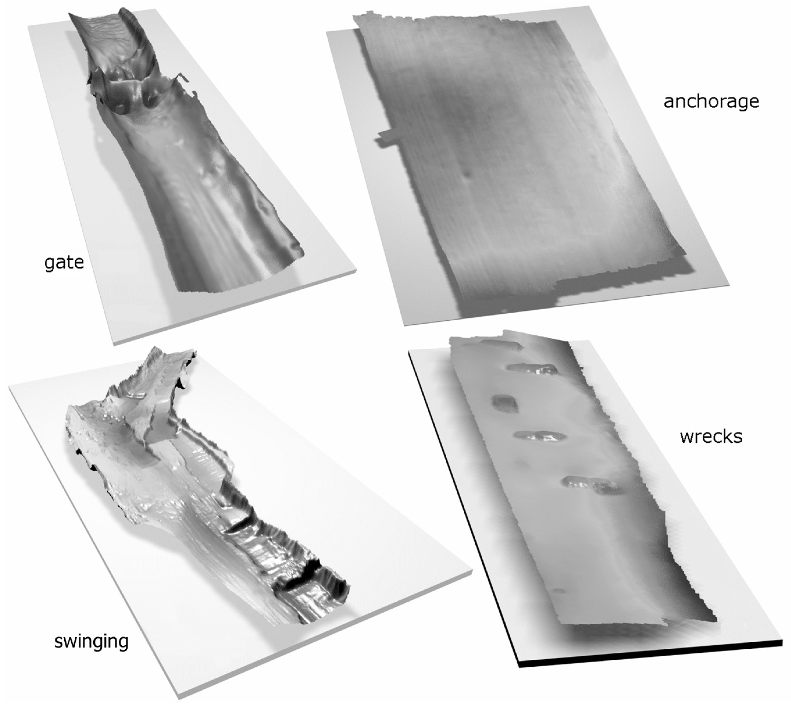
The measurements contain data collected from Szczecin Lagoon and Pomeranian Bay (courtesy of Maritime Office in Szczecin, Poland). The parameters of created test surfaces are presented in Table 1. The three-dimensional visualizations of these sample data are shown in Figure 2. As can be seen, each surface has different geomorphological properties; for example, Gate is a visualization of a route gate, Wrecks presents an area with car wrecks, Swinging is a place where rapid changes of depth are visible, and Anchorage is a flat anchorage ground. They were intentionally chosen since they represent most often occurring types of sea floor. While the sea floor in most areas in the world is not so variable, the results of the experiments should be representative and give a good approximation of the projected efficiency of the method.

3.2. Test Protocol

During experiments, for each test surface we created several multiresolution grid structures with a P E equal to 1, 5, 10, and 25 cm. It should be noted that, for similar conditions and sea-floor types, the IHO recommends an accuracy of 30 cm [22]. For each single case, the number of resulting blocks of 1 × 1, 2 × 2, 4 × 4, 8 × 8, 16 × 16, and 32 × 32 elements was calculated. The compression ratio ( C R ) was estimated, taking into consideration areas with known bathymetric information. Each test surface was analyzed independently. The results are presented in the following tables and figures.

3.2.1. Gate Area

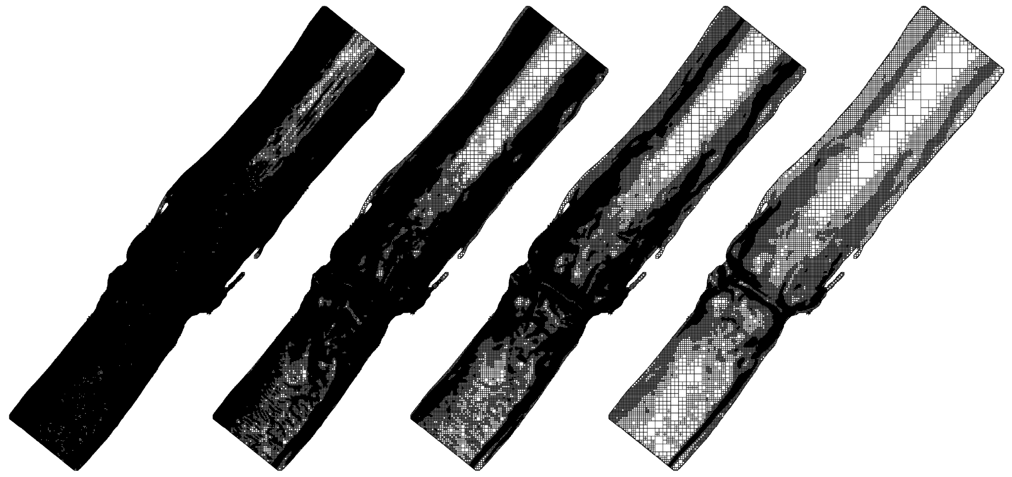
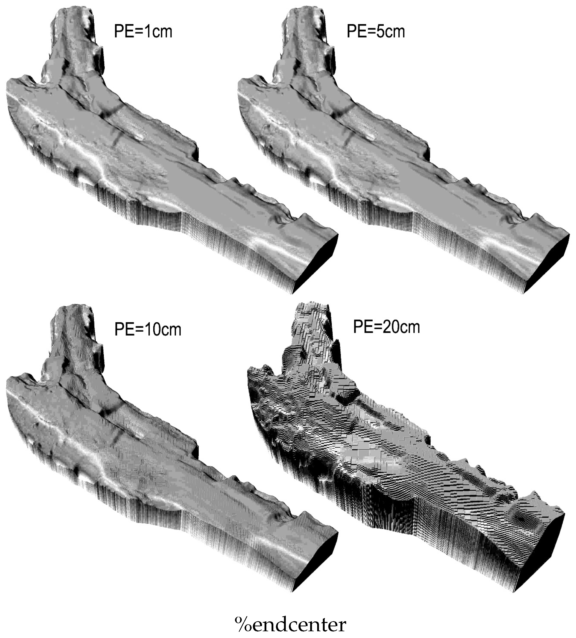
The surface shape of the Gate is quite variable. On the small area, the depth changes from 4 to 22 m. Moreover, there is an artificial riffle on the sea floor, leading to a significant depth drop in its area. There are some sloping areas, characteristic of deepened fairways. The significant variability of sea floor together with the high required reconstruction accuracy ( P E = 1 cm) makes the multiresolution depth grid contain mostly 1 × 1 blocks, so the data reduction rate is very low ( C R = 5.5%). For lower accuracies ( P E = 5 cm–10 cm), the multiresolution grid contains more blocks of 1 × 1 and 2 × 2 values, yet the C R is equal to 60–80%. For P E = 25 cm, the multiresolution depth grid contains mostly blocks of 2 × 2 and 4 × 4 elements, and the latter blocks are dominant. In such case, C R = 94%. It should be noted that the lowest compression is observed for border areas, which is important for a precise outline storage, and for areas of high depth variations, which should not be averaged. The complete results are given in Table 2 and the visualizations of the grids are presented in Figure 3.

3.2.2. Anchorage Area

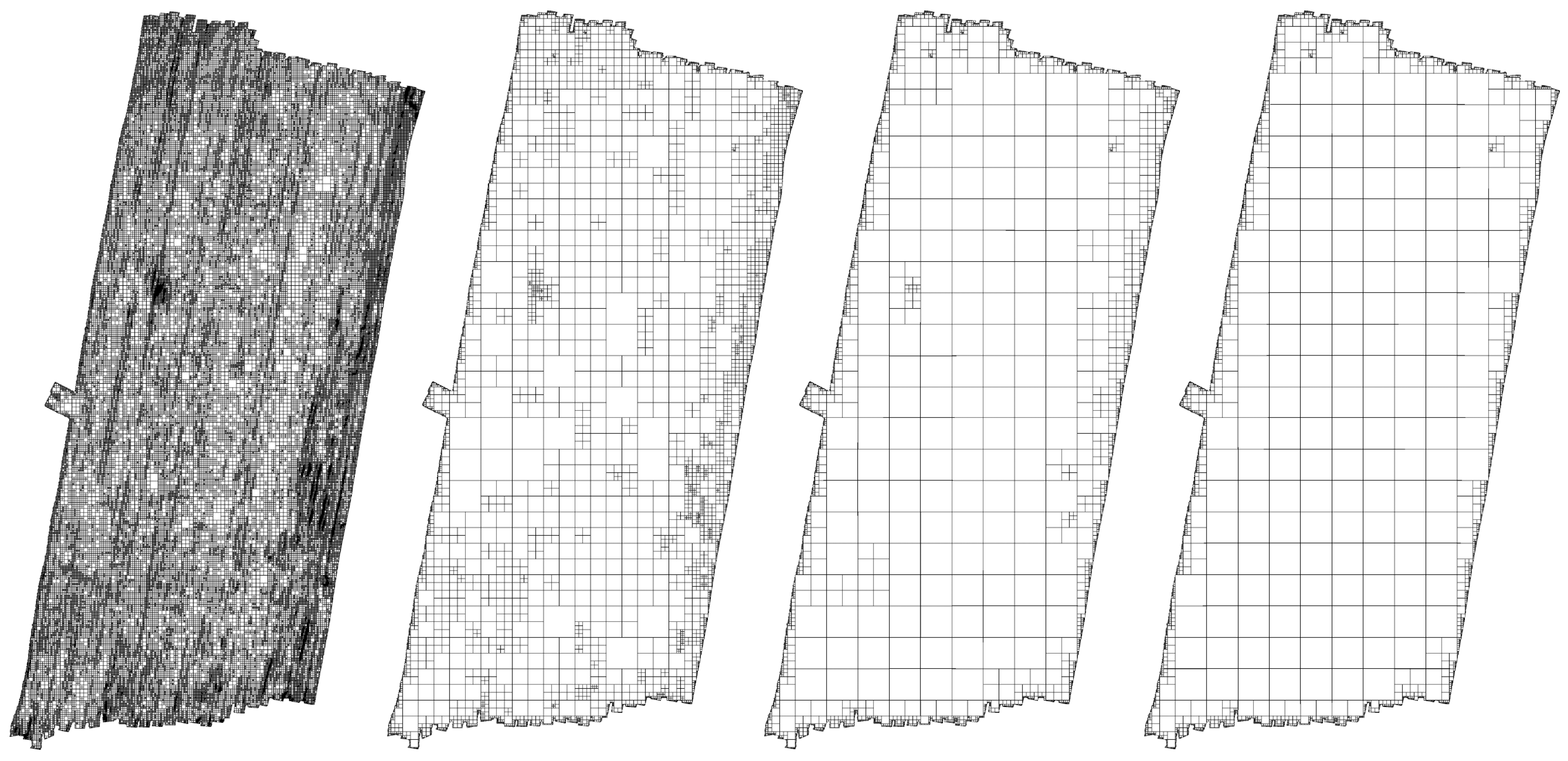
The Anchorage is an example of an often-encountered sea floor with rather flat characteristics. There are no sudden steps or depth changes. Such features make the compression ratio C R very high, even with low P E values (from 70% for P E = 1 cm to 96% for P E = 25 cm). A closer analysis unveils that the blocks of 1 × 1 and 2 × 2 values are used only for outline representation. The inner area is decomposed into blocks of 4 × 4 and 8 × 8 elements (for P E = 1–5 cm) and 32 × 32 (for P E = 10–25 cm).
If the entire surface were filled with similarly flat blocks, the C R could reach 99%, since only the information about the surface outline can be stored. Generally speaking, the maximal theoretical C R value is equal to 99 . 9 % for blocks of 32 × 32 elements, since, for each block, only one value can be stored. The complete results are given in Table 3 and the visualizations of the grids are presented in Figure 4.

3.2.3. Swinging Area

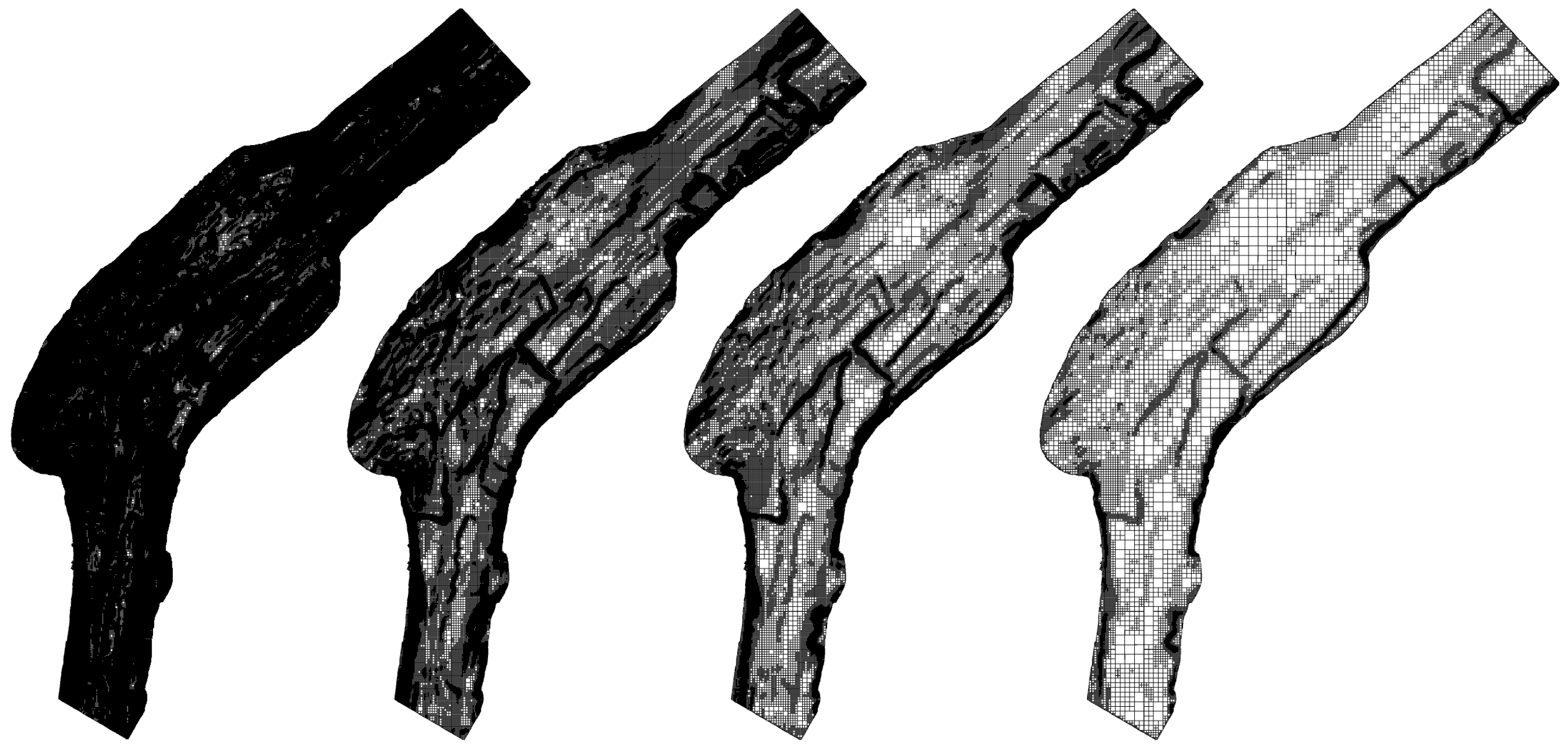
The shape of the sea floor in the case of Swinging area is an effect of deepening works, so there are many rapid and irregular depth changes as well as other untypical forms. Moreover, the outline is quite complex. Hence, taking into consideration the high reconstruction accuracy, the compression ratio is not very high. For P E = 1 cm, it is equal to 20%. For higher values of P E (5 cm, 10 cm, and 25 cm), the C R is equal to 77%, 89%, and 96%, respectively. In almost all cases, the blocks of 1 × 1 and 2 × 2 are put in border areas as well as in areas of sudden depth changes. The complete results are given in Table 4 and the visualizations of the grids are presented in Figure 5.

3.2.4. Wrecks Area

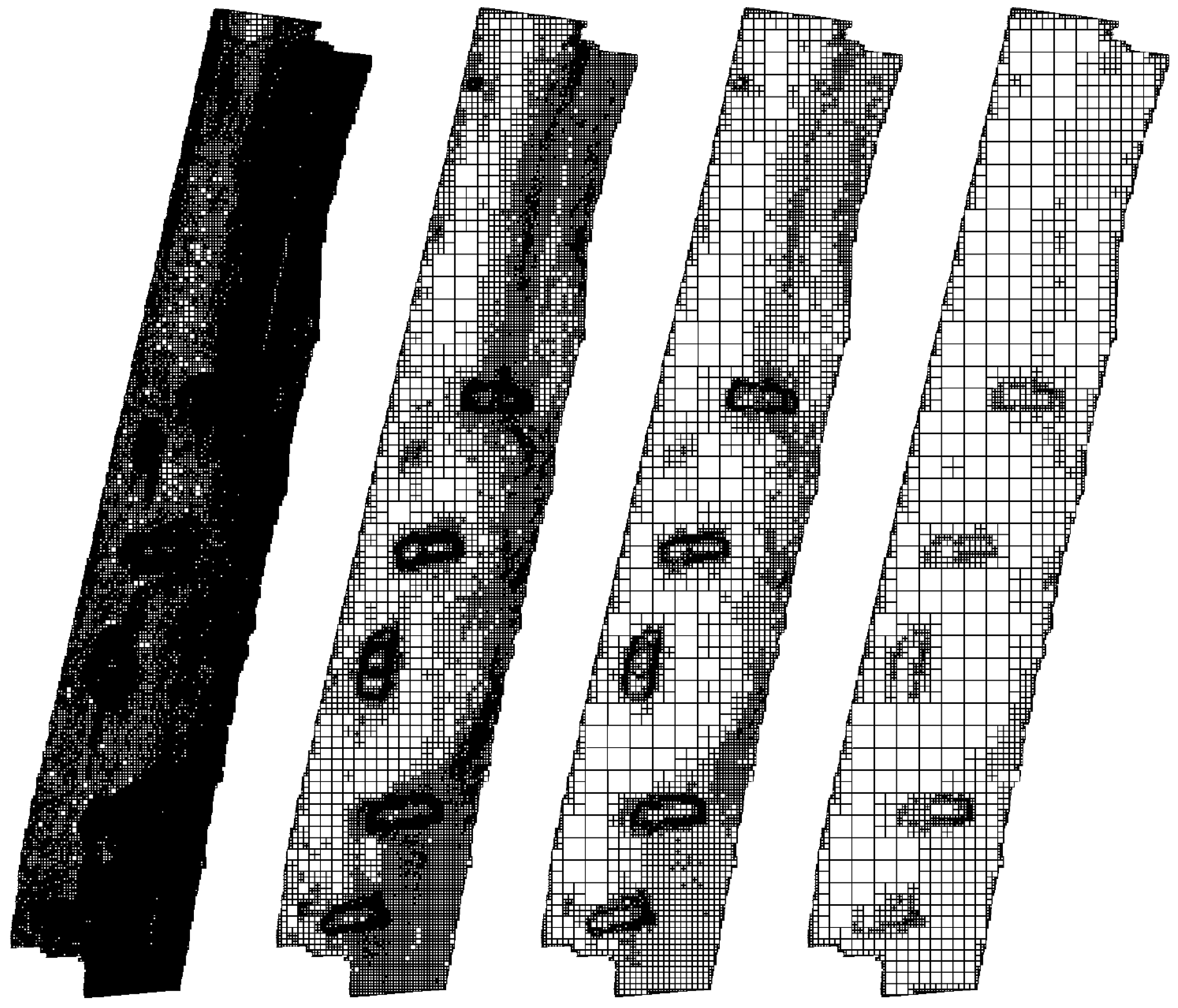
The Wrecks area is rather flat with a slight slope. There are five car wrecks over the area. Hence, it is an example of an area of low diversity with several characteristic objects, which should be precisely represented. When creating the multiresolution depth grid for this surface, for P E = 1 cm, we obtain a compression ratio C R = 50%. In such a case, the structure contains many blocks of 1 × 1 in border areas and areas of car wrecks. In other places, it contains blocks of 2 × 2 and 4 × 4, which are sufficient to precisely describe it. For higher P E values (more than 5 cm), the number of 1 × 1 blocks falls down, while the number of larger blocks rises. Hence, the C R is equal to over 90 % . This exemplary surface shows clearly the advantages of the proposed structure. In areas of small depth variability, the resolution is lower and the blocks are larger (the compression ratio is higher), while in areas of high variability the compression drops down (the blocks are smaller, containing the amount of information comparable to the input gird structure). The complete results are given in Table 5 and the visualizations of the grids are presented in Figure 6.

3.3. Analysis of the Results

Summarizing the above presented results, one can make three general observations:
  • for P E = 1 cm, the compression ratio is low, approximately 50% for surfaces that do not vary much and 10–20% for surfaces that have more variation;
  • for P E = 5 cm, the compression ratio is equal to 60–75% for surfaces that do not vary much and 90–95% for surfaces that have more variation;
  • for P E = 10 cm and P E = 25 cm, the compression ratio is higher than 90%.
It should be stressed that, during the processing of large surfaces, the number of small blocks needed for border representation will be lower, but the compression ratio could be even higher. Generally, for P E = 5 cm (such a value may be accepted in all practical applications, e.g., creating charts, GIS, and hydrography), the compression rate C R can reach 90%.
Nonuniform block decomposition (from 1 × 1 to 32 × 32) depends mainly on two factors: whether the analyzed block is adjacent to the border of the area and how variable it is. The first one is related to the precise, lossless outline representation. In such a case, the gird has a low density. The latter takes into consideration sudden depth changes, crucial from the perspective of safety. In such a case, the grid is represented with high density.
One can see from Figure 7 that the visual quality of the reconstruction (which, however, is not the priority) for a P E 10 cm is almost perfect and that the differences from the highest quality reconstruction are slightly visible.

4. Comparison with Other Methods

It should be also remembered that the multiresolution depth grid is not an alternative to other traditional compression methods applied for DTM data collected in regular grids. The methods that are adapted to the specific characteristics of depth data (often working in the spectral domains) yield higher compression ratios, but they work on regular, uniform grid data. In previous work, we investigated near-lossless compression methods based on discrete cosine transform (DCT) [23], wavelets [24] and principal component analysis (PCA) [25,26]. As a comparison, below in Table 6, the compression ratios for exactly the same benchmark surfaces, compressed with other methods are presented.
In comparison to the above-mentioned methods, the compression ratio achieved with the help of the multiresolution depth grid is slightly lower, but the differences in many cases are not significant and are still at an acceptable level. Taking into consideration that this reduction is performed through local averaging of data, the results obtained are satisfactory.
It should be noted that it is difficult to compare obtained results with those presented by other research teams and described in other scientific articles. While being tested on different benchmark data, the presented algorithms have various goals and requirements, regarding the accuracy of the models created. So far, unfortunately, there have been no reference databases containing various DTM data (also including grid structures), on the basis of which it would be possible to compare the experimental results.

5. Conclusions

In the paper, we present a novel application of a multiresolution depth grid data structure applied to seafloor shape representation with a required, predefined reconstruction accuracy. The data structure is accompanied by algorithms that are used to create the structure from regular uniform grids and then transform that structure back. As is shown, the multiresolution depth grid structure had to fulfill two important objectives. First, it had to represent a certain surface with data collected in a grid with a variable resolution (density). Such a resolution should depend on the surface shape. Second, it had to feature an efficient data volume reduction. In parallel, the compression ratio had to take into consideration the pre-defined reconstruction error (i.e., the P E ).
The experiments show that a significant data volume reduction can be achieved with P E = 5 cm ( C R = 60–90%). These values are acceptable from a practical point of view. They are high enough for a successful reduction and, at the same time, are acceptably low for a precise reconstruction of bathymetric data. It should be stressed that P E = 5 cm is only one-fifth of the permissible uncertainty of bathymetry data suggested by the IHO for the presented benchmark surfaces.
The other key property of the multiresolution depth grid, i.e., the variable resolution of the seafloor structures according to its local configuration, is fully implemented in the proposed method. The smallest blocks of data are usually used when the unaltered information is to be saved (outline of the surface and everywhere where there are significant changes in depth). This seems most important from a practical point of view. Larger blocks are then used in the case of any atypical forms or objects on the sea floor. Stored information, in this case, not only is accurate (consistent with specific P E ) information about the depth but also is a local outline of the object. This is clearly a great advantage of the developed multiresolution depth grid structure.
Algorithms for transforming data from the uniform grid to the multiresolution depth grid and opposite are based on block-based processing. They are recursive and work very quickly. It is also very important when processing large volumes of data.
It should be noted that the original data representation influences the minimum size of a sub-area, so it is equal to the size of the node in the regular grid and there is no possibility of creating denser and thus more accurate grids. The solution to this problem is to create a multiresolution depth grid directly from the measurement data (survey data), which are typically more densely distributed than the data created on the basis of a regular grid. One can consider introducing more flexible conditions based on P E , which does not need to be a static value for the entire processed surface, but must be dependent on depth, the local form of the sea floor, or the presence of objects on the sea floor. Such a solution may be taken into consideration when conducting further studies.
It should be emphasized that the presented method of creating a multiresolution grid is not an optimal method of data compression. Methods such as ones based on DCT, Wavelets, PCA, and others operating in the frequency domain usually feature a superior data reduction rate. Although the main purpose of a multiresolution grid is to represent selected sub-areas with different resolution, it can be also applied to reduce the amount of data. It is possible that the density of the grid in some specific sub-areas can depend not only on the accuracy requirements, but also on other factors such as the depth of a given place, the presence of unusual objects on the sea floor, and the function of the sub-area (e.g., the port or the channel).
Further research may be focused on the development of a combined method that joins the multiresolution grid with compression in the frequency domain. It is possible that such a method will further reduce the amount of data. Hence, the applied structure will make it possible to describe a large area with variable mesh density in different sub-areas. Such an approach will lead to the creation of more complex models describing varied areas of the seabed, with different horizontal and vertical accuracy, while maintaining significant data reduction.

Author Contributions

Wojciech Maleika conceived and designed the study. Michał Koziarski made substantial contributions to the implementation of the algorithm. Paweł Forczmański contributed analysis of the data and the verification of experimental results. The manuscript was written by Wojciech Maleika and Pawel Forczmanski. All authors read and approved the submitted manuscript, agreed to be listed, and accepted this version for publication.

Conflicts of Interest

The authors declare no conflict of interest.

References

  1. Wessex Archaeology. Explore the Seafloor. 2010. Available online: http://ets.wessexarch.co.uk/recs/how-we-study-the-seafloor/geophysical-survey/ (accessed on 19 February 2018).
  2. Łubczonek, J.; Stateczny, A. Concept of Neural Model of the Sea Bottom Surface; Rutkowski, L., Kacprzyk, J., Eds.; Neural Networks and Soft Computing; Physica-Verlag HD: Heidelberg, Germany, 2003; pp. 861–866. [Google Scholar]
  3. Maleika, W. Development of a Method for the Estimation of Multibeam Echosounder Measurement Accuracy. Prz. Elektrotech. 2012, 88, 205–208. [Google Scholar]
  4. Gosciewski, D. Selection of interpolation parameters depending on the location of measurement points. GISci. Remote Sens. 2013, 50, 515–526. [Google Scholar]
  5. Wlodarczyk-Sielicka, M.; Stateczny, A. Clustering Bathymetric Data for Electronic Navigational Charts. J. Navig. 2016, 69, 1143–1153. [Google Scholar] [CrossRef]
  6. Maleika, W.; Palczynski, M.; Frejlichowski, D. Interpolation Methods and the Accuracy of Bathymetric Seabed Models Based on Multibeam Echosounder Data; Pan, J.S., Chen, S.M., Nguyen, N.T., Eds.; Intelligent Information and Database Systems; Springer: Berlin/Heidelberg, Germany, 2012; pp. 466–475. [Google Scholar]
  7. Samet, H. Foundations of Multidimensional and Metric Data Structures (The Morgan Kaufmann Series in Computer Graphics and Geometric Modeling); Morgan Kaufmann Publishers Inc.: San Francisco, CA, USA, 2005. [Google Scholar]
  8. Heckbert, P.S.; Garland, M. Survey of Polygonal Surface Simplification Algorithms. 1997. Available online: http://www.dtic.mil/dtic/tr/fulltext/u2/a461098.pdf (accessed on 19 February 2018).
  9. Cignoni, P.; Montani, C.; Scopigno, R. A comparison of mesh simplification algorithms. Comput. Graph. 1998, 22, 37–54. [Google Scholar] [CrossRef]
  10. Luebke, D.P. A Developer’s Survey of Polygonal Simplification Algorithms. IEEE Comput. Graph. Appl. 2001, 21, 24–35. [Google Scholar] [CrossRef]
  11. Gerstner, T. Multiresolution Compression and Visualization of Global Topographic Data. GeoInformatica 2003, 7, 7–32. [Google Scholar] [CrossRef]
  12. Ben-Moshe, B.; Serruya, L.; Shamir, A. Image Compression Terrain Simplification. In Proceedings of the 19th Canadian Conference on Computational Geometry (CCCG2007), Ottawa, ON, Canada, 20–22 August 2007; pp. 125–128. [Google Scholar]
  13. Pajarola, R. Overview of Quadtree-based Terrain Triangulation and Visualization; Volume 2, Issue 1 of Technical Report; Department of Information & Computer Science, University of California: Irvine, CA, USA, 2002. [Google Scholar]
  14. Lau, T.Y.; Li, Y.; Xie, Z.; Franklin, W.R. Sea Floor Bathymetry Trackline Surface Fitting Without Visible Artifacts Using ODETLAP. In Proceedings of the GIS’09 17th ACM SIGSPATIAL International Conference on Advances in Geographic Information Systems, Seattle, WA, USA, 4–6 November 2009; ACM: New York, NY, USA, 2009; pp. 508–511. [Google Scholar]
  15. Xie, Z.; Franklin, W.R.; Cutler, B.; Andrade, M.A.; Inanc, M.; Tracy, D.M. Surface compression using over-determined Laplacian approximation. In Proceedings of the Advanced Signal Processing Algorithms, Architectures, and Implementations XVII, San Diego, CA, USA, 26–30 August 2007. [Google Scholar]
  16. Pajarola, R.; Gobbetti, E. Survey of Semi-regular Multiresolution Models for Interactive Terrain Rendering. Vis. Comput. 2007, 23, 583–605. [Google Scholar] [CrossRef] [Green Version]
  17. Danovaro, E.; Floriani, L.D.; Magillo, P.; Puppo, E.; Sobrero, D. Level-of-detail for data analysis and exploration: A historical overview and some new perspectives. Comput. Graph. 2006, 30, 334–344. [Google Scholar] [CrossRef]
  18. Mahdavi-Amiri, A.; Harrison, E.; Samavati, F. Hierarchical grid conversion. Comput. Aided Des. 2016, 79, 12–26. [Google Scholar] [CrossRef]
  19. Weiss, K.; De Floriani, L. Simplex and Diamond Hierarchies: Models and Applications. Comput. Graph. Forum 2011, 30, 2127–2155. [Google Scholar]
  20. Mahdavi-Amiri, A.; Samavati, F. Atlas of connectivity maps. Comput. Graph. 2014, 39, 1–11. [Google Scholar] [CrossRef]
  21. Sadeghi, J.; Samavati, F.F. Smooth reverse subdivision. Comput. Graph. 2009, 33, 217–225. [Google Scholar] [CrossRef]
  22. International Hydrographic Organization. IHO Standards for Hydrographic Surveys, Special Publication No. 44, 5th Edition. 2008. Available online: http://www.iho.int/iho_pubs/standard/S-44_5E.pdf (accessed on 27 July 2016).
  23. Forczmanski, P.; Maleika, W. Predicting the Number of DCT Coefficients in the Process of Seabed Data Compression. In Proceedings of the CAIP 2015 16th International Conference Computer Analysis of Images and Patterns, Valletta, Malta, 2–4 September 2015; pp. 77–87. [Google Scholar]
  24. Maleika, W.; Forczmanski, P. Wavelets in Adaptive Compression of Data Describing Sea-Bottom. In Proceedings of the ACS 2002 9th International Conference Advanced Computer Systems, Miedzyzdroje, Poland, 23–25 October 2002; pp. 381–387. [Google Scholar]
  25. Maleika, W.; Czapiewski, P. Evaluation of KLT method for controlled lossy compression of high-resolution seabed’s DTM. Earth Sci. Inform. 2015, 8, 595–607. [Google Scholar] [CrossRef]
  26. Forczmanski, P.; Maleika, W. Near-Lossless PCA-Based Compression of Seabed Surface with Prediction. In Proceedings of the ICIAR 2015 12th International Conference Image Analysis and Recognition, Niagara Falls, ON, Canada, 22–24 July 2015; pp. 119–128. [Google Scholar]
Figure 1. Scheme of an MBES survey (based on [1]).
Ijgi 07 00119 g001
Figure 2. Real surfaces used in the investigations.
Ijgi 07 00119 g002
Figure 3. Multiresolution depth grid for the Gate surface ( P E = 1, 5, 10, and 25 cm).
Ijgi 07 00119 g003
Figure 4. Multiresolution depth grid for the Anchorage surface ( P E = 1, 5, 10, and 25 cm).
Ijgi 07 00119 g004
Figure 5. Multiresolution depth grid for the Swinging surface ( P E = 1, 5, 10, and 25 cm).
Ijgi 07 00119 g005
Figure 6. Multiresolution depth grid for Wrecks surface ( P E = 1, 5, 10, and 25 cm).
Ijgi 07 00119 g006
Figure 7. The visualization of the Swinging area represented with multiresolution depth grids for P E = 1, 5, 10, and 20 cm.
Ijgi 07 00119 g007
Table 1. Characteristics of benchmark surfaces.
SurfaceGrid ResolutionGrid AreaNo. PointsBinary Filesize
(meters)(meters)(Thousand Nodes)(MBytes)
Achorage13008 × 1696510130.38
Swinging0.752464 × 1760433619.61
Gate0.51888 × 1632308113.59
Wrecks0.011856 × 67212474.00
Table 2. The number of blocks and compression ratio for the Gate surface.
Sub-Block Size PE
1 cm5 cm10 cm25 cm
1 × 1686,516183,42457,4284232
2 × 224,130106,66777,91822,385
4 × 42959839618,07016,766
8 × 826169615954423
16 × 1612155155417
32 × 320214996
C R 5.5%60.4%79.5%93.6%
Table 3. The number of blocks and compression ratio for the Anchorage surface.
Sub-Block Size PE
1 cm5 cm10 cm25 cm
1 × 16435643164316431
2 × 215,884292529252925
4 × 456,311144714391439
8 × 826,5291003697697
16 × 1624541079344320
32 × 3224287130743080
C R 70.8%95.7%96.0%96.0%
Table 4. The number of blocks and compression ratio for the Swinging surface.
Sub-Block Size PE
1 cm5 cm10 cm25 cm
1 × 1812,458136,16649,1784838
2 × 2101,88096,73346,38818,473
4 × 4422532,92426,05510,113
8 × 892324272495700
16 × 1601376231820
32 × 320118217
C R 20.1%76.6%88.7%96.4%
Table 5. The number of blocks and compression ratio for the Wrecks surface.
Sub-Block Size PE
1 cm5 cm10 cm25 cm
1 × 1109,570801027982030
2 × 239,088952637771305
4 × 44205739129981084
8 × 811814401755636
16 × 160285347484
32 × 3201168148
C R 49.5%91.2%96.1%98.1%
Table 6. CR values [%] for different benchmark surfaces and other previously developed near-lossless compression methods ( P E = 5 cm). DCT: discrete cosine transform; PCA: principal component analysis.
MethodTest Area
GateAnchorageSwingingWrecks
DCT [23]92.296.788.695.0
Wavelets [24]93.097.991.196.6
PCA [26]96.199.393.798.1
Multiresolution Depth Grid60.495.776.691.2