Article

Efficient Algorithm for Constructing Order K Voronoi Diagrams in Road Networks

1
State Key Laboratory of Information Engineering in Surveying, Mapping and Remote Sensing, Wuhan University, Wuhan 430079, China
2
Collaborative Innovation Center of Geospatial Technology, Wuhan University, Wuhan 430079, China
3
Hubei Luojia Laboratory, Wuhan 430079, China
4
Geocomputation Center for Social Sciences, Wuhan University, Wuhan 430079, China
5
School of Management, Huazhong University of Science and Technology, Wuhan 430074, China
6
School of Remote Sensing and Information Engineering, Wuhan University, Wuhan 430079, China
*
Author to whom correspondence should be addressed.
ISPRS Int. J. Geo-Inf. 2023, 12(4), 172; https://doi.org/10.3390/ijgi12040172
Submission received: 4 February 2023 / Revised: 4 April 2023 / Accepted: 6 April 2023 / Published: 19 April 2023

Abstract

:
The order k Voronoi diagram (OkVD) is an effective geometric construction to partition the geographical space into a set of Voronoi regions such that all locations within a Voronoi region share the same k nearest points of interest (POIs). Despite the broad applications of OkVD in various geographical analysis, few efficient algorithms have been proposed to construct OkVD in real road networks. This study proposes a novel algorithm consisting of two stages. In the first stage, a new one-to-all k shortest path finding procedure is proposed to efficiently determine the shortest paths to k nearest POIs for each node. In the second stage, a new recursive procedure is introduced to effectively divide boundary links within different Voronoi regions using the hierarchical tessellation property of the OkVD. To demonstrate the applicability of the proposed OkVD construction algorithm, a case study of place-based accessibility evaluation is carried out. Computational experiments are also conducted on five real road networks with different sizes, and results show that the proposed OkVD algorithm performed significantly better than state-of-the-art algorithms.

1. Introduction

The Voronoi diagram (VD) is one of the fundamental geographical constructions for partitioning a geographical space through a competitive means [1,2,3,4]. Specifically, the VD partitions the geographic space into a set of Voronoi regions based on a given set of points of interest, also known as generators. Each Voronoi region contains all the locations that share the same nearest generator, allowing for space tessellation and providing an adjacency structure for topology generation [5]. In addition, a Voronoi region can be used as container for geographical entities, making it an effective indexing structure for organizing spatial data. Due to these unique characteristics, the VD has been widely used in various geographical applications, such as mobile phone data analysis [6], facility service area delimitations [7], spatial data mining [8,9], and etc.
The order k Voronoi diagram (OkVD) is a generalization of the VD that has also received significant attention in the literature [1,10,11]. Given a set of generators, the OkVD is meant to partition the geographical space into a set of order k Voronoi regions (OkVR), where all locations within an OkVR share the same k nearest generators. These generators are determined by their order of proximity to the location, i.e., the first nearest generator, the second nearest generator, and so on until the kth nearest generator. This OkVD provides an effective tool to determine k nearest generators for any location, which is a critical step for numerous spatial analysis tasks, such as spatial interpolations [12], accessibility evaluations [13], and k nearest neighbor queries [14,15,16]. Given the broad applications of the OkVD in the geographical analysis, it is therefore necessary to develop efficient algorithms for constructing OkVDs in real-world geographical spaces.
In the literature, efficient algorithms for constructing Voronoi diagrams (VDs) have been the subject of much research. Early studies focused on the construction of VDs in homogeneous and isotropic planar spaces, where the distance between any two locations is measured by Euclidean distance [3,17]. However, recognizing that movements in urban areas is generally constrained by road networks, Erwig [18] first proposed a network Voronoi diagram (NVD) model for partitioning the urban geographical space. The NVD model quantifies distances between any two locations in the road network explicitly by using shortest path algorithms to compute the network distance [19]. Building on this work, Okabe et al. [1] developed an efficient algorithm for constructing NVDs by modifying conventional shortest path algorithms. Ohsawa [20] applied the concept of Order k Voronoi region for solving the problem of k nearest neighbor queries. As an alternative approach, Ai et al. [2] proposed an NVD construction algorithm by discretizing each road link into a set of linear units of equal length and using the stream flowing approach to construct NVDs. Chen et al. [21] proposed several new NVD models for partitioning the urban geographic space constrained by multi-mode public transport networks and developed effective algorithms for constructing NVDs in public transport networks.
To the best of our knowledge, there are few algorithms in the literature have been developed to construct order k NVD (OkNVD) in real road networks, with the notable exception of Okabe et al. [1]. For convenience, this algorithm is hereafter referred to as Okabe’s algorithm. This algorithm consists of two stages. In the first stage, the k nearest generators for each node are determined by performing the one-to-all shortest path algorithm (e.g., Dijkstra’s algorithm) F times to construct completed one-to-all shortest path trees rooted at all generators, where |F| is the number of generators. The k nearest generators for each node can be determined by sorting F shortest paths from all generators to the node. In the second stage, the OkNVD is constructed by determining all nodes and links belonging to each order k network Voronoi region (OkNVR). The idea of a lower-bound envelope is introduced to divide boundary links that belongs to at least two OkNVRs. Although Okabe’s algorithm is straightforward and easy to implement, the first stage of Okabe’s algorithm tends to have computational overheads, because it calculates too many unnecessary shortest paths, given that F is generally much larger than the k value. Furthermore, no detailed procedure was provided for implementing the idea of a lower-bound envelope method in the second stage.
Along the line of previous work [1], this study proposes an effective and efficient algorithm for constructing OkNVD in road networks. The proposed algorithm also consists of two stages, which extends the previous algorithm in the following aspects.
  • A new one-to-all k shortest path procedure is proposed in the first stage to efficiently determine the k nearest generators at each node. As an extension of Okabe’s algorithm, the proposed procedure simultaneously constructs |F| shortest path trees in a single path searching process, sharing the same priority queue to coordinate the construction of shortest path trees from different generators. Unlike Dijkstra’s algorithm [22], the proposed procedure closes a node after it has been selected from the priority queue k times from different generators, allowing it to exactly determine the shortest paths from the k nearest generators. This results in partial shortest path trees being constructed, improving Okabe’s algorithm. Furthermore, the proposed procedure can directly determine the order of k nearest generators according to their order of selection from the priority queue without the need for shortest path sorting at each node.
  • A new recursive procedure is introduced in the second stage to effectively divide boundary links into different OkNVRs. This study rigidly proves the hierarchical tessellation property of OkNVD. Specifically, each order j NVR is covered by a set of order j + 1 NVRs, and these order j + 1 NVRs are mutually exclusive except at the boundary points (j = 0, 1, …, k − 1). Using this hierarchical tessellation property, the introduced procedure, therefore, can recursively divide every boundary link into the order first, second, …, until the kth NVRs.
  • To demonstrate the applicability of the proposed OkNVD construction algorithm, a comprehensive case study of evaluating place-based accessibility is carried out in Shenzhen, a mega-city in China. Computational experiments are also conducted using five real road networks with various settings of k and F values. Results show that the proposed OkVD algorithm performed significantly better than state-of-the-art algorithms.
The remainder of this article is organized as follows. Section 2 gives the model formulation of OkNVD and proves its hierarchical tessellation property. Section 3 describes the proposed OkNVD construction algorithm. Section 4 reports the numerical example of OkNVD application in place-based accessibility, and computational experiments using five real road networks. Section 5 presents the conclusions together with recommendations for future research in the area.

2. Model Formulation of Order k Network Voronoi Diagrams

The list of notations used in this article is summarized in Abbrevations. A road network can be represented by a directed graph, G N , A , consisting of a set of nodes N , and a set of links A . Each link a i j ϵ A has a tail node n i ϵ N and a head node n j ϵ N , and a positive link cost t i j   (length or travel time). Each node n j has a set of successor nodes S U C C n j and a set of predecessor nodes P R E D n j . Any location q in the road network can be represented as a i j ,   θ q using the linear reference technique [23], where θ q 0 ,   1 is the relative position on the link a i j . The values of θ q = 0 and θ q = 1 refer to the tail and head nodes of the link respectively. With location q , the link a i j   can be divided into two partial links a i q and a q j , and their link costs are assumed to be proportional to relative positions as:
t i q = t i j θ q
t q j = t i j 1 θ q
Let p o q be the shortest path from origin o to destination q . The path cost, denoted by t o q , can be calculated by the summation of corresponding link costs along the path:
t o q = l i j t i j δ i j o q
where δ i j o q is the binary variable of link-path incidence relationship, δ i j o q = 1 indicates link a i j on the path p o q and otherwise δ i j o q = 0 .
Let F = f 1 , , f i , , f F be a set of generators located in the road network, where F is the number of generators in F . Generators are typically a certain type of service facility. Given any location q in the network, its first outward nearest generator, denoted by f o u t q , 1 F , satisfies:
t 1 f q t i f q , f i F f o u t q , 1
where t 1 f q is the cost of the shortest path from generator f o u t q , 1 to location q and t i f q is the cost of the shortest path from any other generator f i f o u t q , 1 (i.e., f i F f o u t q , 1 ) to location q . Subsequently, its k th outward nearest generator, denoted by f o u t q , K F , can be identified as that satisfying:
t K 1 f q   t K f q t i f q ,   f i F f o u t q , 1 , , f o u t q , K 1
Then, the set of k outward nearest generators can be determined and denoted by F o u t q , K = f o u t q , 1 , , f o u t q , K . Therefore, the outward OkNVD (order k network Voronoi diagram), denoted by V D o u t K , is to partition the road network into a set of sub-networks, called outward OkNVRs (order k network Voronoi regions), denoted by , v r O u t K , i , , such that all locations within any v r O u t K , i share the same set of k nearest generators, F o u t q , K . The outward OkNVR, v r O u t K , i , can be expressed as
v r O u t K , i = q | t 1 f q t i f q , f i F F o u t q , 1 t K f q t i f q , f i F F o u t q , K 1
where ∧ represents that all conditions are satisfied simultaneously.
Because the road network is directed, the inward OkNVD can also be defined by using the shortest path in a reverse direction from location q to the corresponding generator. Let F i n q , K = f i n q , 1 , , f i n q , K be the set of k inward nearest generators. The j th inward nearest generator satisfies following condition:
t j q f t i q f ,   f i F F i n q , j 1
where t j q f is the cost of the shortest path from location q to the j th inward nearest generator f i n q , j . Then, the inward OkNVD, denoted by V D i n K , consists of a set of inward OkNVRs, V D i n K = , v r i n K , i , . Each inward OkNVR, v r i n K , i , delimits all locations sharing the same set of k inward nearest generators, F i n q , K , and it can be mathematically expressed as
v r i n K , i = q | t 1 q f t i q f , f i F F i n q , 1 t K q f t i q f , f i F F i n q , K 1
The outward and inward OkNVDs are applicable for different types of generators and different applications. The outward OkNVDs are commonly for emergency facilities (e.g., fire stations) and applications whose outward travel cost t i f q is critical; while the inward OkNVDs are usually for service facilities (e.g., supermarkets and shopping malls) and applications whose inward travel cost t i q f is critical.
Figure 1 and Figure 2 illustrate the outward and inward OkNVDs in a well-known small road network, namely the Sioux Falls network. Figure 1a,b respectively give the outward and inward OkNVDs when k = 1 , in which OkNVDs degrade to the classical outward and inward NVDs. In both two figures, generators are given in star shapes, and their Voronoi regions are shown in the same color. As can be seen, the outward NVDs are not identical to the inward counterparts, since the road network is directed. It can also be seen that both outward and inward NVDs form a tessellation on the road network with two observations: (1) All NVDs cover the whole network (i.e., collectively exhaustive); and (2) Voronoi regions are mutually exclusive except at the boundary points. This is because the Sioux Falls network (as most real road networks) is fully connected, i.e., there exists at least one path between any two locations in the road network.
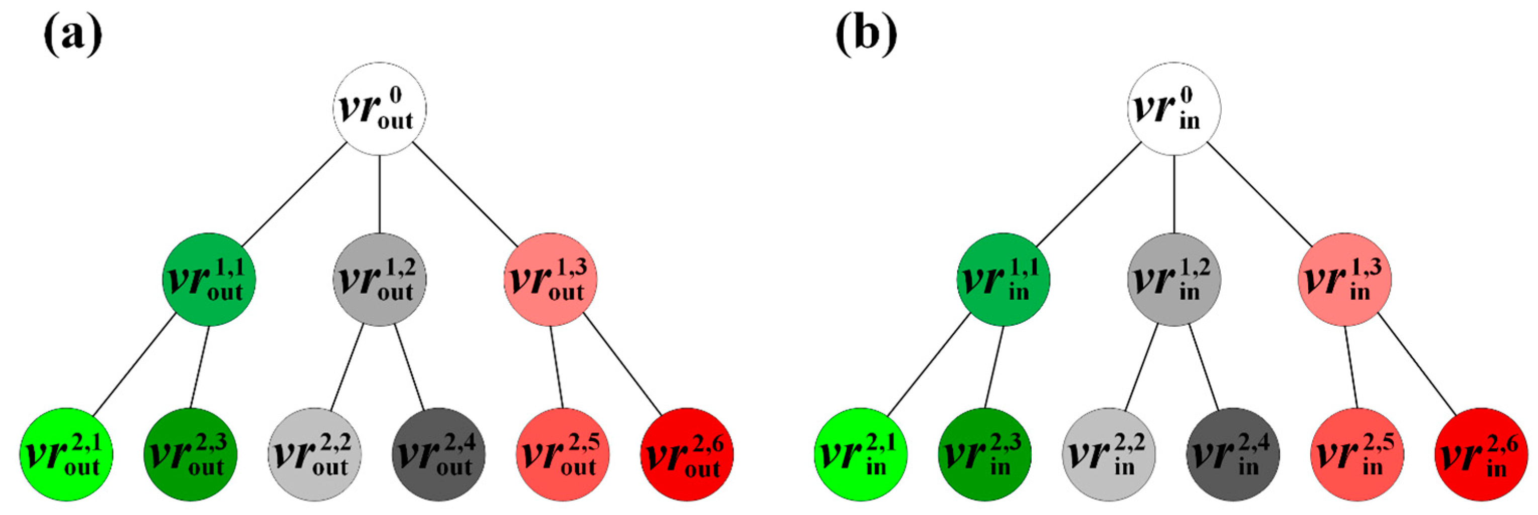
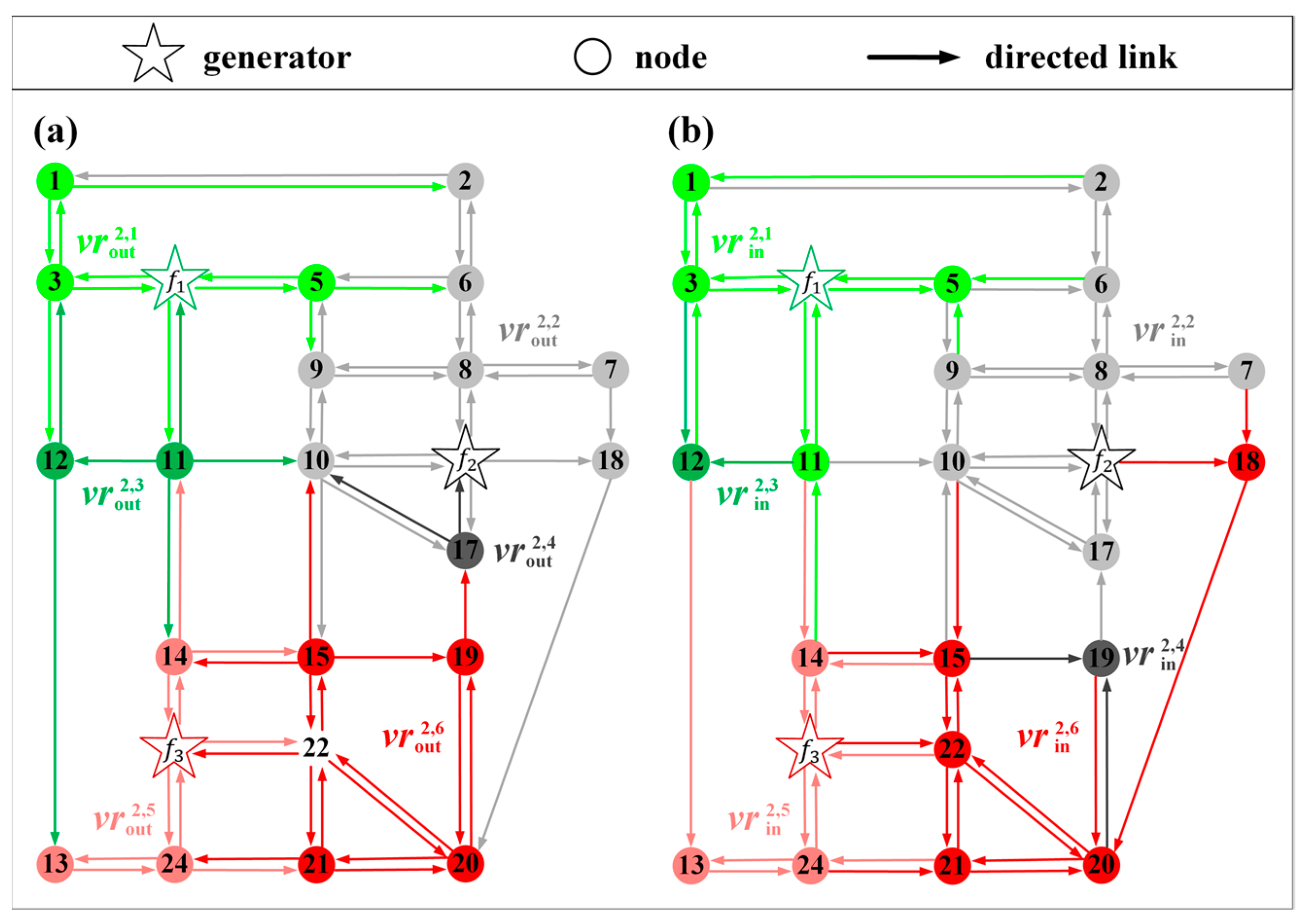
Figure 2a,b respectively shows the outward and inward OkNVDs when k = 2 in the same Sioux Falls network. In these two OkNVDs, six OkNVRs are given in different colors. Each OkNVR delimits all locations sharing the same k nearest generators. For example, all locations within in v r o u t 2 , 1 have the same first and second nearest generators, f 1 and f 2 . As can be seen, the outward (or inward) order second NVDs not only form a tessellation on the whole network but also on each outward (or inward) order first NVR. Thereby, the order-second NVD together with the order first NVD form a hierarchical tessellation on the road network. This hierarchical tessellation can also be represented by the tree structure shown in Figure 3a,b, in which the Voronoi regions were kept the same color as Figure 2a,b. The original road network is represented as a single root node at level 0 of the tree. The order first NVD is to partition the original network into a set of order first NVRs, which are represented as child nodes of nodes at level 1. Each order first NVR is further divided into a set of order second NVRs representing as its child nodes, i.e., nodes at level 2.
Since both outward and inward OkNVDs have an identical tessellation property, we only present the outward case for simplicity. Given a OkNVR, v r o u t K , i , it is said to be a child region of order k 1 NVR, v r o u t K 1 , i , if F o u t q , K = F o u t w , K 1 f o u t q , K holds. All child NVRs of v r o u t K 1 , i form the child region set, denoted by CRS o u t K 1 , i = , v r o u t K , i , V R o u t K . Conversely, this v r o u t K 1 , i is said to be the parent region of any   v r o u t K , i CRS o u t K 1 , i . The tessellation property of OkNVD can be proved rigidly as below.
Proposition 1. 
If the road network is fully connected, the outward order first NVD forms a tessellation on the road network.
Proof. 
See Proposition A1 in the Appendix A. □
Proposition 2. 
If the road network is fully connected,   C R S o u t K 1 , i   forms a tessellation on   v r o u t K 1 , i .
Proof. 
See Proposition A2 in the Appendix A. □
According to Propositions 1 and 2, OkNVRs are stacked under their parent NVRs (i.e., order k 1 NVRs, …, until the order first NVRs), forming a k level hierarchical tessellation on the road network. This hierarchical tessellation property of OkNVDs can be useful for many applications to organize spatial data. Such a property is fully utilized in the next section to construct OkNVDs.

3. Proposed Algorithm for Constructing OkNVDs

This section presents the proposed algorithms for constructing outward and inward OkNVDs in the road network. We first describe the algorithm for constructing outward OkNVD, called ConstructOutwardOkNVD. As shown in Algorithm 1, this ConstructOutwardOkNVD algorithm consists of two stages. The first stage is to efficiently determine the shortest paths to F o u t j , K at each node n j . To this end, a new one-to-all k shortest path finding procedure, called FindKNearestPOIs, is proposed. The second stage is to construct the outward OkNVD. Each node n j only belongs to a OkNVR and can be easily determined using the calculated F o u t j , K . However, a link a i j may belong to multiple OkNVRs. In the second stage, a recursive procedure, called AddLinkToOkNVRs, is introduced to effectively divide the link into corresponding OkNVRs using the above hierarchical tessellation property. The detailed steps of FindKNearestPOIs and AddLinkToOkNVRs procedures are described in the following sections.
Algorithm 1: Detailed steps of the proposed algorithm.
Procedure: ConstructOutwardOkNVD
Inputs: Road network G , Generator set F , and k value
Returns: Outward OkNVD
Stage 1. K nearest generators search:
01: Call procedure FindKNearestPOIs to calculate F o u t j , K for each node n j .
Stage 2. The OkNVD construction:
02: For each node n j N
03:   Retrieve the node’s v r o u t K , i using F o u t j , K , and add n j into v r o u t K , i .
04: End For
05: For each link pair of a i j and a j i
06: Call procedure AddLinkToOkNVRs( a i j , a j i ) to divide the link into corresponding OkNVRs.
07: End For
06: Return OkNVD.

3.1. The FindKNearestPOIs Procedure

To calculate shortest paths from F o u t j , K at each node n j , a straightforward approach [1] consists of two steps. The first step is to perform the classical one-to-all Dijkstra’s algorithm by F times to construct the completed one-to-all shortest path trees rooted at all generators. Accordingly, F   shortest paths from all generators at each node n j are calculated. The second step is to sort the calculated F shortest paths at each node to determine F o u t j , K . Using the F-Heap data structure [24], Dijkstra’s algorithm runs in the worst-case complexity of O N Log N + A , where N is the number of nodes and A is the number of links. Therefore, the step requires O F N Log N + F A . Since the second step requires O ( N F 2 ) , this approach runs in the worst-case complexity of O ( F N Log N + F A + N F 2 ) . Such an approach is easy for implementation. However, its computational performance significantly degrades with F , i.e., the number of generators. It tends to have computational overheads by calculating too many unnecessary shortest paths, given that F is generally much larger than the k value in practice.
In this study, a new one-to-all k shortest path procedure, i.e., FindKNearestPOIs, is proposed to efficiently determine only k shortest paths from F o u t j , K rather than F shortest paths from all generators. The proposed procedure modifies the Dijkstra’s algorithm in three aspects. Firstly, the proposed procedure simultaneously constructs F shortest path trees in a single path searching process. The Dijkstra’s algorithm maintains only one label at each node. The proposed procedure, however, maintains a label list with F size at each node to record the shortest paths from different generators. Secondly, the proposed procedure makes use of only one priority queue for constructing all F shortest path trees. By sharing a single priority queue, shortest path trees from all generators can be coordinated during the path-searching process. Thirdly, the proposed procedure closes a node when it was selected from the priority queue by k times instead of a single selection used in Dijkstra’s algorithm. After the node was closed, k shortest paths from F o u t j , K   were exactly determined at the node according to the monotonic increasing property of the priority queue. In addition, the ascending order of shortest paths from different generators can be directly obtained according to their selection order from the priority queue. Therefore, the proposed procedure can efficiently determine k shortest paths from F o u t j , K without the requirement of constructing F completed shortest path trees from all generators and sorting the shortest paths at each node.
Algorithm 2 gives the detailed steps of the proposed FindKNearestPOIs procedure. Unlike Dijkstra’s algorithm, each node n j in the proposed procedure maintains three objects, including a label set L S j , a selected generator set S G j and an open status o s j . The label set L S j employs an array list structure with the size of F . The ith location of the label set, denoted by L S j i , records the shortest path from the ith generator f i . This way efficiently retrieves the shortest path from a specific generator. Note that it is not necessary to generate F labels at each node; and a null object is used if the shortest path from a certain generator has not been generated. The selected generator set, S G j , employs a linked list structure for recording the order of generators whose shortest paths to node n j were selected from the priority queue. Finally, the open status o s j is a binary indicator, and o s j = true indicates that n j is open.
In the initialization step, L S j and S G j of all nodes are set to be empty, and o s j of all nodes are set to be true. A path (or called label) from each generator f i to itself, denoted by p f f , is created and set its path cost t f f as zero. An additional property, denoted by g f f , is introduced at the label to store the generator order i . This created path is added into the priority queue, denoted by S E .
At each iteration, a path p f j at the top of the priority queue S E is selected. Its generator order, g f j , is then added into the selected generator set S G j . Once the number of generators in S G j reached the k value, the node n j is closed by setting the o s j attribute to be false. In this case, k shortest paths from F o u t j , K have been determined at node n j , and thus all paths of L S j still in the priority queue are eliminated without considerations. Subsequently, the selected path p f j is extended to its successor nodes, which are not closed. Through an open successor node n w , a temporal path p ˜ f w is created by p f j a j w , where is a path concatenation operator. The newly created path p ˜ f w compares to the existing path p f w as L S w g ˜ f w from the same generator. If the existing path p f w = or t ˜ f w < t f w holds, the newly created path is kept and inserted into the priority queue; and it is discarded otherwise. The procedure continues the path selection and extension process until S E is empty. When the procedure terminates, it can determine the k nearest generators of each node n j (i.e., F o u t j , K ) at the selected generator set S G j and k shortest paths from F o u t j , K of each node n j at the label set L S j .
Algorithm 2: Detailed steps of the FindKNearestPOIs procedure.
Procedure: FindKNearestPOIs
Inputs: Road network G , Generator set F , and k value
Step 1. Initialization:
01: For each node n j N
02:   Set label set L S j as an empty array list with F size.
03:   Set selected generator set S G j , and Set open status o s j t r u e .
04: End For
05: Initialize the priority queue S E .
06: For each generator f i F
07:   Create path p f f from f i to itself, and Set cost as t f f : = 0 and generator as g f f i .
08:   Set L S i g f f : = p f f and add the path into S E S E p f f .
09: End For
Step 2. Path selection:
10: If S E = , Then Stop.
11: Select the path p f j at the top of S E and remove it from S E S E p f j .
12: Add the path’s generator into S G j S G j g f j .
13: If the size of S G j equals to K Then
14: Set o s j f a l s e .
15: For each p e j in L S j
16:  If p e j S E , Then remove it from S E S E p e j .
17: End For
18: End If
Step 3. Path extension:
19: For each successor node n w S U C C n j
20: If o s w = t r u e Then
21:  Create path p ˜ f w : = p f j a j w , and Set t ˜ f w : = t f j + t j w and g ˜ f w g f j .
22:  Retrieve existing path p f w L S w g ˜ f w .
23:  If p f w = or t ˜ f w < t f w Then
24:   If p f w S E , Then remove it from S E S E p f w .
25:   Set p f w p ˜ f w , t f w t ˜ f w , g f w g ˜ f w and L S w g ˜ f w p f w .
26:   Add p f w into S E S E p f w .
27:  End If
28:   End If
29: End For
30: Go back to Step 2.
We can prove the optimality of the proposed FindKNearestPOIs procedure as below.
Proposition 3. 
When the proposed FindKNearestPOIs procedure terminates, it can determine shortest paths from K nearest generators   F o u t j , K   for all nodes.
Proof. 
See Proposition A3 in the Appendix A. □
The worst-case complexity of the proposed FindKNearestPOIs procedure is analyzed. Using the F-Heap data structure [24], the selection of the minimum cost path from the priority queue requires O Log F N , and both remove and add path into the priority queue requires O 1 , where F N is the maximum paths in the priority queue. Since k N is the maximum number of path selection from the priority queue, the proposed procedure thus runs in the worst-case complexity of O k N Log F N + k A . This complexity is significantly better than the previous Okabe’s algorithm, i.e., O ( F N Log N + F A + N F 2 ) .

3.2. The AddLinkToOkNVRs Procedure

In Okabe’s algorithm [1], a complicated idea of a lower-bound envelope was introduced to divide boundary links which belong to at least two distinctive OkNVRs. However, no detailed procedure was given to implement such an idea.
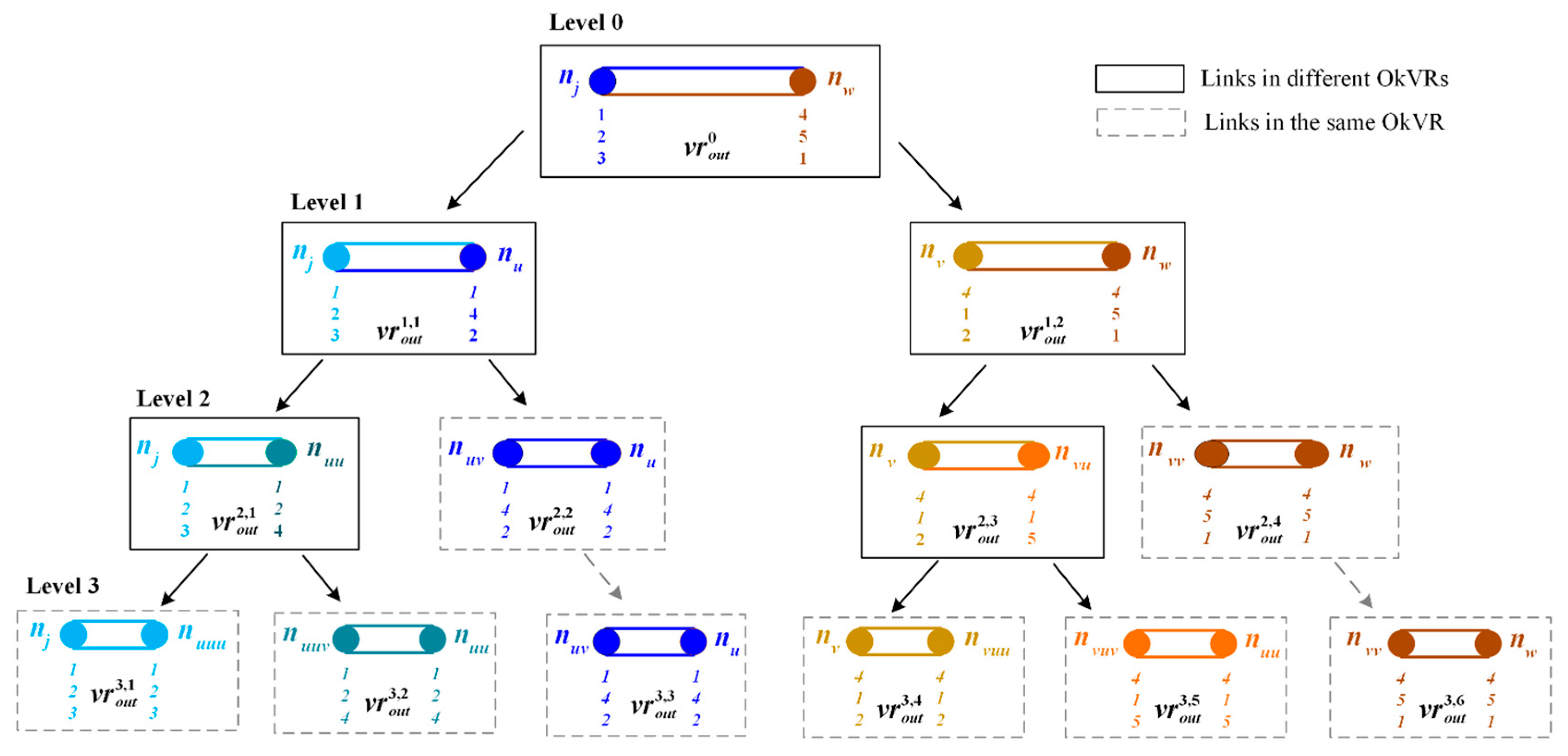
In this study, a new recursive procedure, AddLinkToOkNVRs, is introduced to effectively divide boundary links into different OkNVRs using the hierarchical tessellation property, i.e., Propositions 1 and 2. The detailed steps of the introduced procedure is given in Algorithm 3. Figure 4 illustrates this procedure using a simple example of two directed links a j w and a w j . Two end nodes, n j and n w , are given in the figure with the selected generator sets, S G j = 1 , 2 , 3 and S G w = 4 , 5 , 1 . Because S G j S G w holds, these two links are not in the same OkNVR, so called boundary links (their end nodes are shown in different colors). This AddLinkToOkNVRs procedure divides boundary links into a set of partial links through the hierarchical tessellation from the first level until the kth level. When dividing links at the first level, we focus on only S G j 1 (i.e., Generator 1) and S G w 1 (i.e., Generator 4) and their shortest paths, p 1 f j = L S j S G j 1 and p 1 f w = L S w S G w 1 .
The procedure consists of three steps. The first step (i.e., Step 2.1) is to divide links a j w and a w j into four partial links. Using the equal travel times between left-bound route p 1 f u = p 1 f j   a j u and right-bound route p 1 f v : = p 1 f w   a w v , we can determine break point θ u on link a j w (or θ v on link a w j ) as
θ u = ( f 1 f w t 1 f j + t w j ) / t w j + t j w
θ v = 1 θ u
Then, the path cost for p 1 f u is calculated as t 1 f u t 1 f j + t j w θ u and its generator is set as g 1 f u g 1 f j . Similar, the path cost for p 1 f v is determined as t 1 f v t 1 f w + t w v θ v and g 1 f v g 1 f w . On the same break point, we create two new nodes, namely a left-bound node n u and right-bound node n v . Then, we divide two links a j w and a w j into four newly partial links, including two left-bound partial links, a j u and a u j , and two right-bound partial links, a v w and a w v . For example, partial link a j u = a j w , 0 ,   θ u represents part of link a j w from 0 to θ u using the linear reference.
The second step (i.e., Step 2.2) is to determine the selected generator sets ( S G u and S G v ) and label sets ( L S u and L S v ) for newly created nodes n u and n v . It is easy to determine S G j 1 (e.g., Generator 1) and S G w 1 (e.g., Generator 4) as the first and second generators of the left-bound node n u , e.g., S G u = 1 , 4 . A reverse order is used for the right-bound node n v , i.e., S G v = 4 , 1 . Since L S u and L S v have identical path sets, we use L S to represent them, i.e., L S 1 = p 1 f u and L S 4 = p 1 f v . Subsequently, we construct candidate paths to determine other k 2 nearest generators in addition to S G j 1 and S G w 1 . Because candidate paths should pass through two end nodes, n j and n w , we construct p l f j   a j u and p l f v : = p l f w   a w v for any path p l f j and p l f w maintained at n j and n w respectively. All constructed candidate paths are inserted into the priority queue, denoted by C S E . Then, the top k 2 paths from C S E are identified and stored at L S , and their generators are inserted into S G u and S G v , e.g., S G u = 1 , 4 , 2 and S G v = 4 , 1 , 2 . After this step was performed, we divided two input links into four partial links within two NVRs, e.g., v r o u t 1 , 1 and v r o u t 1 , 2 , at the first level.
The last step (i.e., Step 2.3) is to recursively call the AddLinkToOkNVRs procedure for the link division at the next level by using the newly created left-bound links ( a j u and a u j ) and right-bound links ( a v w and a w v ) as two input links respectively.
For the link division at the ith level, this procedure focuses on only Scenario 2 of S G j i S G w i . This is because we have Scenario 1 of S G j l = S G w l for l = 1 , , i , in which S G j l and L S j [ S G j [ l ] ] are kept for the setting ( S G u and S G v ) and label sets ( L S u and L S u ) at the ith level. The link division of the ith level has the similar three steps as that of the first level. This procedure recursively performed until Scenario 3 of S G u l = S G v l for l = 1 , , k holds. After the procedure terminated, input links were divided into a set of partial links belonging to different OkNVRs, e.g., v r o u t 3 , 1 ,…,   v r o u t 3 , 6 in the illustrative example.
Algorithm 3: Detailed steps of the AddLinkToOkNVRs procedure.
Procedure: AddLinkToOkNVRs
Inputs: Links a jw and a wj
01: Set SG : = and Set LS as empty array lists with F size.
02: For i : = 1 to k
03: If SG j i = SG w i Then (Scenario 1)
04:   Set SG : = SG SG j i and LS SG j i : = LS j SG j i .
05: Else (Scenario 2)
Step 2.1. Divide two links into four partial links:
06:   Retrieve p i fj : = LS j SG j i and p i fw : = LS w SG w i .
07:   Calculate θ u : = t i fw t i fj + t wj / t wj + t jw and θ v : = 1 θ u .
08:   Create left-bound path p i fu : = p i fj   a ju and Set t i fu t i fj + t jw θ u and g i fu g i fj .
09:   Create right-bound path p i fv : = p i fw   a wv and Set t i fv t i fw + t wv θ v and g i fv g i fw .
10:   Create left-bound node n u and partial links a ju : = a jw , 0 ,   θ u and a uj : = a wj ,   θ v , 1 .
11:   Create right-bound node n v and partial links a vw : = a wj , θ u ,   1 and a wv : = a jw , 0 ,   θ v .
Step 2.2. Set the selected generator set and the label set for two newly created nodes:
12:   Set LS SG j i p i fu and LS SG w i p i fv .
13:   Set SG u : = SG SG j i and SG v : = SG SG w i .
14:   If Size SG u < k Then
15:     Set SG u : = SG u SG w i and SG v : = SG v SG j i .
16:     Set priority queue CSE : = .
17:     For l : = i + 1 to k
18:    Retrieve p l fj : = LS j SG j l and p l fw : = LS w SG w l .
19:    Create candidate path p l fu : = p l fj   a ju and Set t l fu t l fj + t jw θ u and g l fu g l fj .
20:    Create candidate path p l fv : = p l fw   a wv and Set t l fv t l fw + t wv θ v and g l fv g l fw .
21:    Add them into CSE CSE p l fu p l fv .
22:  End For
23:  For m : = Size SG u to k
24:    Select the path p l fm at the top of CSE and remove it from CSE CSE p l fm .
25:    Set SG u SG u g l fm and SG v SG v g l fm .
26:    Set LS g l fm   p l fm .
27:  End For
28:   End If
29:   Set LS u LS and LS v LS .
Step 2.3. Recursively divide four newly created partial links:
30:   Call AddLinkToOkNVRs a ju , a uj and AddLinkToOkNVRs a vw , a wv .
31:   Return.
32:   End If
33: End For
34: Add a jw and a wj into vr out K , i using SG j as the k nearest generators. (Scenario 3)
We can prove the optimality of the introduced AddLinkToOkNVRs procedure below.
Proposition 4. 
When the introduced AddLinkToOkNVRs procedure terminates, it can correctly divide two input links into a set of OkNVRs.
Proof. 
See Proposition A4 in Appendix A. □
The worst-case complexity of the introduced AddLinkToOkNVRs procedure is also analyzed. In the procedure, Step 2.1 runs in O 1 ; and Step 2.2 runs in O k Log k using the F-heap data structure. Because the procedure recursively divides input links from the first level until the k level, it runs in the complexity of O k 2 Log k .

3.3. Complexity Analysis of the Proposed OkNVD Construction Algorithms

With Propositions 3 and 4, we can easily prove the optimality of the proposed ConstructOutwardOkNVD algorithm as follows.
Proposition 5. 
When the ConstructOutwardOkNVD algorithm terminates, it can correctly construct outward OkNVDs in the road network.
Proof. 
It can be easily followed by Propositions 3 and 4. □
Based on the worst-case complexity of AddLinkToOkNVRs procedure (see Section 3.2), we can determine that the second stage of the ConstructOutwardOkNVD algorithm runs in O A k 2 Log k . Since its first stage runs in O k N Log F N + k A (see Section 3.1), the ConstructOutwardOkNVD algorithm therefore runs in O k N Log F N + A k 2 Log k .
The proposed ConstructOutwardOkNVD algorithm can be modified easily to construct inward OkNVDs, namely the ConstructInwardOkNVD algorithm. Both FindKNearestPOIs and AddLinkToOkNVRs procedures should be modified by using the backward search (i.e., path extension to predecessor nodes) instead of the forward search (i.e., path extension to successor nodes). For example, the modified FindKNearestPOIs procedure should create a new path p ˜ w f : = a j w p f j from each predecessor node n w P R E D n j (see Lines 19 and 22). The ConstructInwardOkNVD algorithm has the same worst-case complexity as the ConstructOutwardOkNVD algorithm.

4. Numerical Experiments

This section reports the numerical experiments using real road networks. The proposed algorithm was implemented using the C# programming language. Section 4.1 reports their applications in place-based accessibility to supermarkets in Shenzhen, China; and Section 4.2 investigates their computational performance in several real road networks with different sizes.

4.1. Place-Based Accessibility to Supermarkets

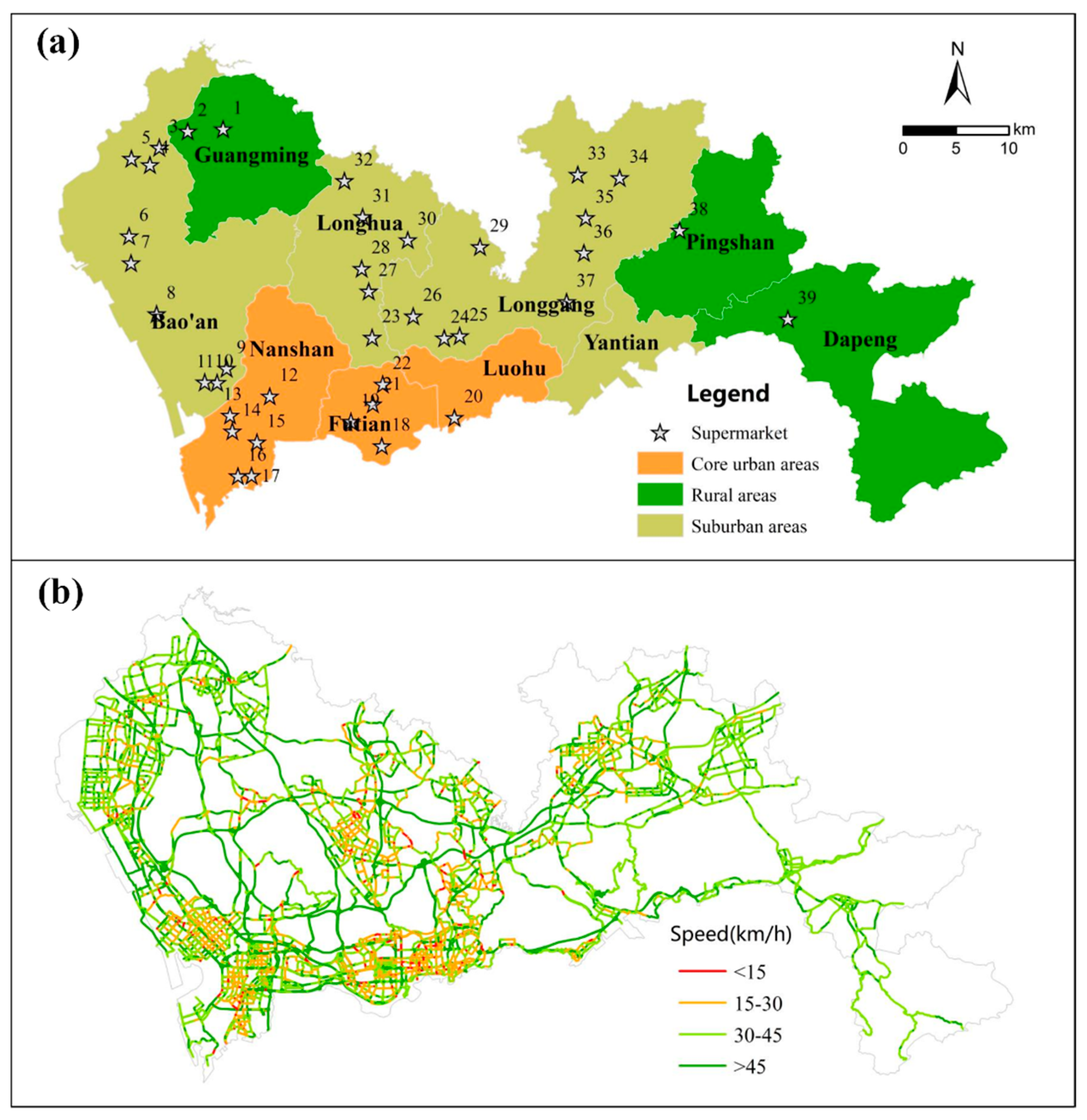
In this study, Shenzhen, one of the most developed mega-cities in China, was selected as the study area. As shown in Figure 5a, Shenzhen is located in southern China, bordering Hong Kong to the south. It is the first Chinese special economic zone and experienced rapid socioeconomic development during the past decades. By the end of 2013, Shenzhen covered an area of approximately 1996 km2 and had a total population of approximately 10.5 million, of which more than 70% were immigrants. Shenzhen has ten administrative districts with diverse land-use patterns. Among these districts, Nanshan, Futian and Luohu are core urban regions with dense residential and commercial areas; Bao’an, Longhua, Longgang, and Yantian are suburban regions with several new towns and industrial areas; and other three districts (Guangming, Pingshan, and Dapeng) are rural regions with large-scale agriculture and hilly lands as well as industrial areas.
Three datasets were collected for the case study. The first dataset was 39 large supermarkets in Shenzhen shown by star symbols in Figure 5a. The second dataset was the road network of Shenzhen city. As shown in Figure 5b, it consisted of 32,065 nodes and 81,618 directed links. The third dataset was trajectories of 17,406 taxis collected on a typical workday, i.e., 23 September 2014. These trajectories were matched onto the road network using a map matching algorithm [17], and then used to estimate and link travel time information during the evening peak hour (18:00–19:00) by using the method of Shi et al. [25].
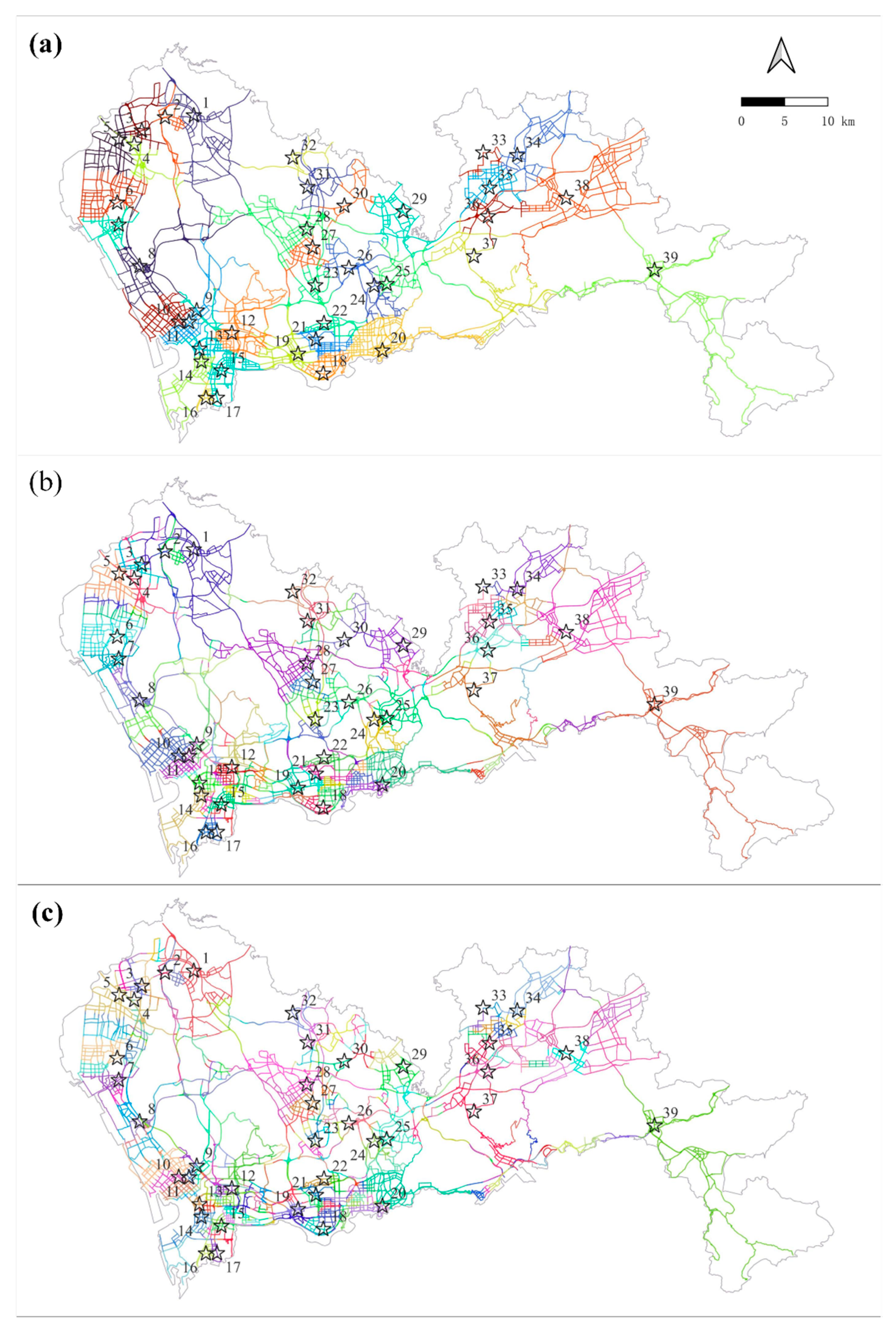
Using supermarkets as generators, Figure 6a shows the constructed inward OkNVD when k = 1 . The generators are shown in star shape. The proposed algorithm constructed 39 inward OkNVRs, i.e., v r i n 1 , i , for all generators. Each OkNVR, shown by a distinctive color, delimits a spatial region in which all locations share the same nearest generator. As can be seen, the sizes of OkNVRs are spatially heterogeneous in Shenzhen city with different supermarket densities, i.e., smaller at core urban and suburban regions (e.g., Nos. 1–5, 9–17 and 18–22) while larger at rural regions (e.g., Nos. 38 and 39). It can also be seen that all OkNVRs formed a tessellation on the Shenzhen network. They covered the whole network and they were mutually exclusive except at the boundary points.
Figure 6b shows OkNVD for large supermarkets in Shenzhen when k = 2 . As can be seen, the proposed algorithm constructed 149 inward OkNVRs, i.e., v r i n 2 , i , in the study area. In this case, each constructed OkNVR delimits a spatial region in which all locations share the same set of the first and second nearest generators, F i n q , 2 . Compared to the case of k = 1 , the sizes of v r i n 2 , i are smaller, especially for those areas with dense supermarkets. This result is obvious because all inward OkNVRs in the case of k = 2 form a tessellation in the case of k = 1 . Each v r i n 1 , i is covered by one or more v r i n 2 , i , which are mutually exclusive except at the boundary points. Figure 6c shows the corresponding OkNVD when k = 3 . In this case, the whole study area was partitioned into 320 inward OkNVRs, i.e., v r i n 3 , i . The constructed OkNVRs when k = 3 further form a tessellation when k = 2 .
Table 1 summarizes the characteristics of OkNVRs under different k values. As can be seen, the average size of OkNVRs (in terms of cumulative link lengths) was reduced with the increase of k values. The total size of all OkNVRs under different k values keep constant, i.e., 5530 km. This is because all OkNVRs at three levels ( k = 1 to 3) are stacked, forming a three-level hierarchical tessellation on the whole road network.
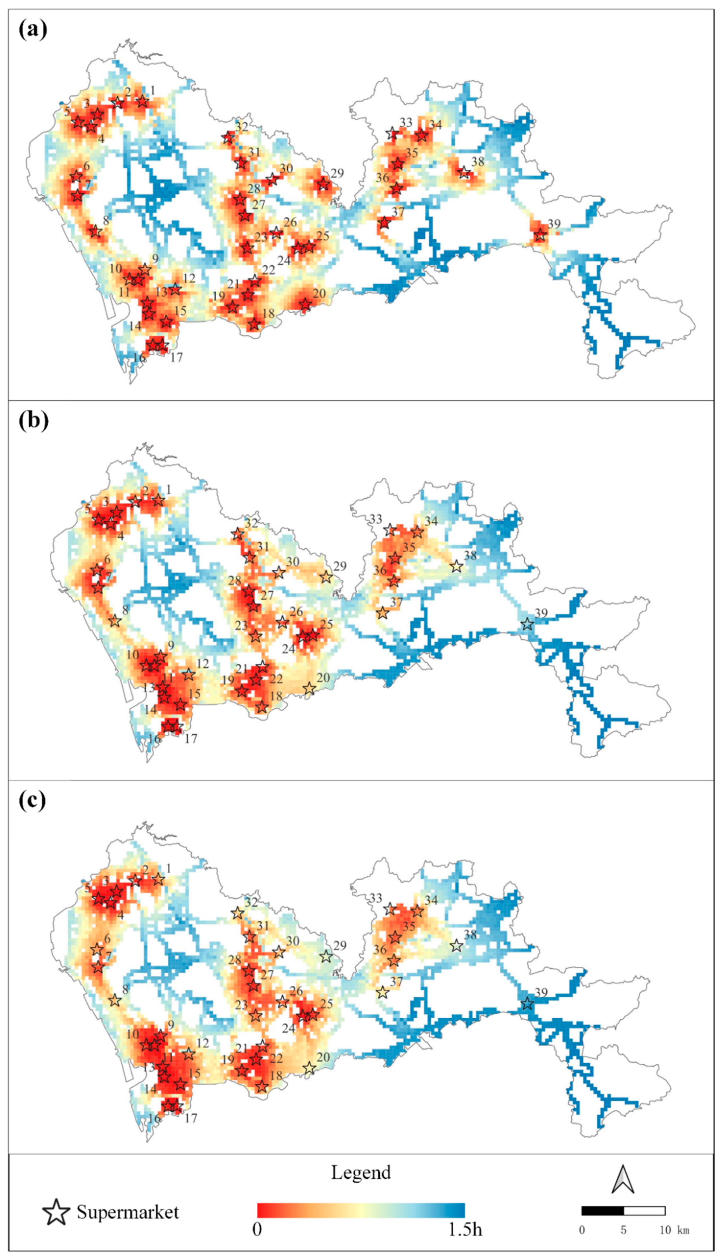
When constructing the inward OkNVD, the least travel times t 1 q f , , f k q f to k nearest generators, F i n q , K = f i n q , 1 , , f i n q , K , for any location q in the road network were calculated. These calculated travel times were employed to quantify the place-based accessibility to large supermarkets in Shenzhen and shown in Figure 7.
Figure 7a shows the accessibility pattern using the least travel time to the nearest supermarket, i.e., t 1 q f calculated in the order first NVD. This is a classical indicator for measuring place-based accessibility in the literature [26]. As can be observed, the level of accessibility to large supermarkets is high for areas surrounded by at least one supermarket but low for those areas far from supermarkets. This indicator assumes that residents always go to the nearest supermarket for food purchases. However, several empirical studies have found that the most frequently used supermarkets by most residents are not the nearest supermarket to home [27]. As an extension to this classical indicator, Chen et al. [28] recently suggested using the average travel time (denoted by t ¯ k q f ) of the k nearest supermarkets to better quantify accessibility to food retailers. Specifically, the accessibility level at location q is calculated as follows:
t ¯ k q f = t 1 q f + + t k q f / k
A smaller t ¯ k q f value implies the easer of a location for accessing supermarkets. This indicator can be directly obtained by using the results of OkNVD. Figure 7b shows the accessibility result using the indicator of t ¯ k q f when k = 2 . Compared to the classical indicator of t 1 q f , this indicator can well reveal the rural–urban disparity of accessibility to supermarkets caused by heterogeneous supermarket densities. The accessibility level was relatively high in the core urban regions (Nanshan, Futian, and Luohu) and relatively low in rural regions (Guangming, Pingshan, and Dapeng). For example, such indicators can well identify the low accessibility level for areas nearby Supermarket No. 39 in Dapeng district, since only one large supermarket is available in those areas. Similarly, a more distinct rural–urban disparity of accessibility can be observed when k = 3 is used, see Figure 7c. As the value of k increases, the accessibility level of a location with low supermarket density would decrease rapidly, as they lack alternative supermarket supplies. However, a large k value could cover infeasible supermarkets with too large travel times. The selection of a suitable k parameter is critical for this accessibility measure. As suggested by Chen et al. [28], k = 3 is appropriate for supermarket accessibility studies.

4.2. Computational Experiments

This section reports the computational performance of the proposed algorithm. Previous Okabe’s algorithm [1] was also implemented for comparisons. Since Okabe’s algorithm did not provide the detailed procedure for the second stage, we employed that of our proposed algorithm. Both algorithms were coded in the same C# programming language and used the same F-heap data structure [24] as the priority queue. Since constructing inward and outward OkNVDs requires the same computational performance, we only report that of inward OkNVD constructions for simplicity. All experiments were conducted on a desktop with a four-core Intel 3.3 GHz CPU (only a single processor was used) and 8GB RAM running on Windows 10 operation system.
Table 2 reports the computational performance of both OkNVD construction algorithms in Shenzhen network under a different number of generators (i.e., F values). Network nodes were randomly selected as new generators. The k value was set as 3. As can be seen, the computational performance of Stage 1 dominates that of both algorithms. Therefore, we only examined the computational performance of Stage 1 hereafter.
It can be seen from the table that the computational time of Okabe’s algorithm (i.e., Stage 1) raised linearly with F . For example, when F = 100 , Okabe’s algorithm consumed 27.49 s to construct inward OkNVD in Shenzhen network. When F = 1000 , the computational time of this algorithm increased by 10.1 times (i.e., 305.19/27.49 − 1) to 305.19 s. This result is expected, mainly because Okabe’s algorithm calculates F shortest paths at each node by constructing F completed shortest path trees rooted at all generators. In addition, computational cost was required to sort F shortest paths at each node.
As shown, the proposed algorithm has a much lower rate of degradation with the increase of F . When F increases from 100 to 1000, its computational time raised by only 91.7% from 2.40 s to 4.60 s. This is because the proposed algorithm calculates only k shortest paths at each node by constructing F partial shortest path trees. Therefore, the proposed algorithm performed significantly faster than Okabe’s algorithm by calculating much less shortest paths, especially for the scenarios of large F . As shown, the proposed algorithm ran 10.45 (i.e., 27.49/2.40 − 1) times faster than Okabe’s algorithm when F = 100 . This computational advantage further increased to 65.34 times when F = 1000 . Such computational advantage is important for real applications commonly with large F , for example F = 6899 in Chen et al. [6].
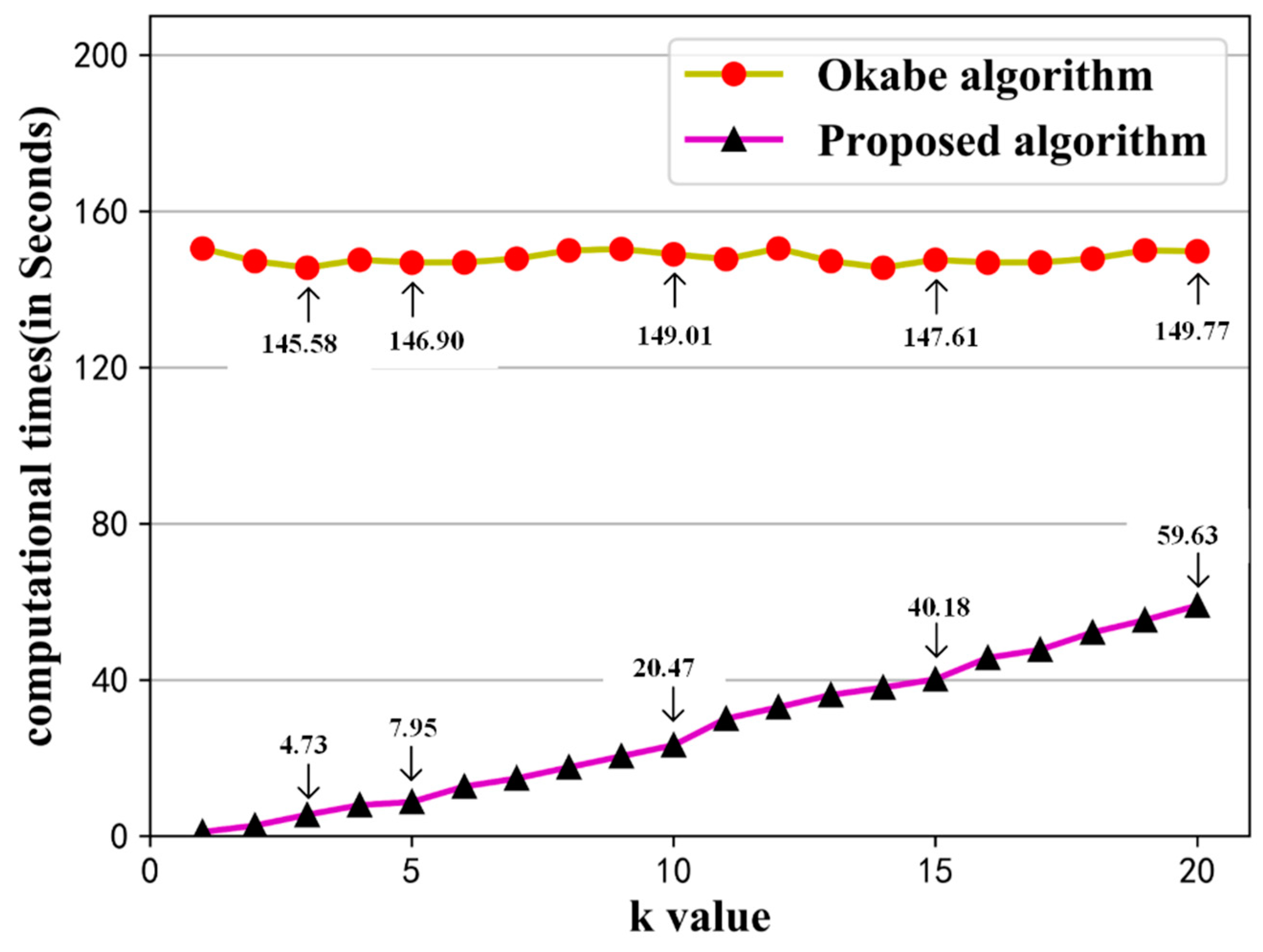
Figure 8 shows the computational performance of both OkNVD construction algorithms in Shenzhen network under different k values. The number of generators was set as 500. As can be seen, the computational performance of Okabe’s algorithm is stable under different k values. It is obvious, since Okabe’s algorithm calculates F shortest paths at each node regardless of different k settings. It can be seen that the computational performance of the proposed algorithm degraded linearly with the increase of k value. This is because the proposed algorithm calculates k shortest paths at each node. The larger the k value was, the more shortest paths were calculated. In practice, the k value is usually low, e.g., k 5 [28]. It should be noted that the proposed algorithm ran still significantly better than Okabe’s algorithm various k values under various k values.
Table 3 reports the computational performance of both testing algorithms in five real road networks with different sizes. The number of generators was selected as 500 and the k value was set as 3. Generators were randomly selected from the network nodes. As shown, the computational times of both testing algorithms increased with the network size. This result is expected, since the computational performance of shortest path algorithms themselves degraded with the network size [19]. It can be seen that the proposed algorithm performed consistently better than Okabe’s algorithm in all road networks with different sizes. For example, in a small network of Xiamen, the proposed algorithm consumed 0.19 s to construct inward OkNVD, which was 36.73 times (i.e., 7.17/0.19 − 1) faster than Okabe’s algorithm. This computational improvement remained relatively stable in all networks ranging from 31 to 37 times.

5. Conclusions

The order k network Voronoi diagram (OkNVD) is an effective geometric construction to partition the network space into a set of order k network Voronoi regions (OkNVRs) such that all locations within an OkNVR share the same k nearest generators. Despite the broad applications of OkNVD, few effective and efficient algorithms had been developed to construct OkNVD in real road networks. This study proposed a novel OkNVD construction algorithm consisting of two stages. In the first stage, a new one-to-all k shortest path procedure was proposed to efficiently determine the k nearest generators for each network node in a single shortest path search process. This proposed procedure improves the worst-case complexity from previous O ( F N Log N + F A + N F 2 ) [1] to O k N Log F N + k A . In the second stage, a new recursive procedure was introduced to effectively divide boundary links into different OkNVRs using the hierarchical tessellation property. The introduced procedure can effectively solve the link division issue that had not been addressed by the previous study [1].
To demonstrate the applicability of the proposed OkNVD construction algorithm, a comprehensive case study in Shenzhen city was carried out. Results of the case study demonstrated that the proposed OkNVD construction algorithm can well quantify place-based accessibility in a fine-gained spatial resolution. Results of computational experiments showed that the proposed algorithm was significantly faster than previous Okabe’s algorithm for all five testing networks under different k and F settings. For example, it performed about 65 times faster than Okabe’s algorithm in the Shenzhen network when k = 3 and F = 1000 . This computational advantage would be more obvious in real large-scale applications, in which the number of generators F are large and the k value is small.
Several directions for future research are worth pursuing. Firstly, this study assumed that link costs are static and deterministic. Traffic conditions in real road networks are dynamic and stochastic [29]. How to incorporate such dynamic and stochastic travel times into the proposed algorithm needs further investigation. Secondly, the proposed algorithm considers only the road transport mode. The extension of this proposed algorithm into the multi-mode transport networks, such as metro and bus, is warranted for further study. Last but not least, finding k nearest generators is a critical step for many network analyses, such as spatial interpolation, spatial clustering, outlier detection, and k nearest neighbor query, etc. [12,14,28]. Subsequent studies should investigate how to incorporate the proposed algorithm in these network analysis methods.

Author Contributions

Bi Yu Chen: Conceptualization, Methodology, Funding acquisition, Writing—original draft, Writing—review and editing; Huihuang Huang: Conceptualization, Methodology, Writing—review and editing; Hui-Ping Chen: Conceptualization, Methodology, Project administration, Writing—review and editing; Xuan-Yan Chen: Writing—review and editing; Wenxuan Liu: Writing—review and editing; Tao Jia: Writing—review and editing. All authors have read and agreed to the published version of the manuscript.

Funding

This research was funded by National Key Research and Development Program (No. 2021YFB3900900), the Fundamental Research Funds for the Central Universities (No. 2042022kf1199), National Natural Science Foundation of China (No. 42271473), the Natural Science Foundation of Hubei Province (2020CFA054), and LIESMARS special Research Funding.

Data Availability Statement

The data that support the findings of this study are available on request from the corresponding author.

Conflicts of Interest

The authors declare no conflict of interest.

Abbreviations

Notations used in this article.
A a set of links in the road network
A number of links in the road network
a i j a network link from tail node n i to head node n j
a i q a partial link from tail node n i to location q
a q j a partial link from location q to head node n j
CRS o u t K 1 , i the child region set of v r o u t K 1 , i
F the set of generators
F i n q , K the set of K inward nearest generators of location q
F o u t q , K the set of K outward nearest generators of location q
F the number of generators
f i n q , 1 first inward nearest generator of location q
f i n q , K Kth inward nearest generator of location q
f o u t q , 1 first outward nearest generator of location q
f o u t q , K Kth outward nearest generator of location q
G road network
k key parameter, such as k nearest generators
L S j label set of node n j
L S j i a label for recording the shortest path from the ith generator f i
N a set of nodes in the road network
N number of nodes in the road network
n i a network node
o a network location
o s j open status
p o q the shortest path from a location o from another location q
p ˜ f w a temporal path from generator f i to node n w
P R E D n j a set of predecessor nodes of node n j
q a network location
S E priority queue for sorting shortest paths
S G j the set of determined generators of node n j
S G j i the ith determined generator of node n j
S U C C n j a set of successor nodes of node n j
t i j cost of link a i j
t o q cost of path p o q
t 1 f q cost of the shortest path from generator f o u t q , 1 to location q
t i f q cost of the shortest path from the ith nearest generator f i to location q
t i q f cost of the shortest path from location q to the ith nearest generator f i
V D i n K inward OkNVD (order k network Voronoi diagram)
V D o u t K outward OkNVD (order k network Voronoi diagram)
v r i n K , i ith inward OkNVR (order k network Voronoi region) of V D i n K
v r O u t K , i ith outward OkNVR (order k network Voronoi region) of V D o u t K
θ q relative position of location q
δ i j o q link-path incidence relationship

Appendix A

Proposition A1. 
If the road network is fully connected, the order first outward (or inward) NVD forms a tessellation on the road network.
Proof. 
We first prove that Voronoi regions of the order first outward NVD are collectively exhaustive as follows. Because the road network is fully connected, we can calculate shortest paths from all generators to a location q . Then, we can determine the location’s first outward nearest generator, f o u t q , 1 F , satisfying t 1 x q t i x q , f i F f o u t q , 1 . According to Equation (6), the location q belongs to a Voronoi region v r O u t 1 , i ( F o u t q , 1 ) . Therefore, any location q in the road network is covered by V R o u t 1 . Thus, the collectively exhaustive property of V R o u t 1 is satisfied.
We then prove that Voronoi regions of the order first outward NVD are mutually exclusive except at the boundary points as below. As proved, we can determine the first outward nearest generator of location q , i.e., f o u t q , 1 F satisfying t 1 x q t i x q , f i F f o u t q , 1 , which can further divide into two scenarios. The first scenario is t 1 x q < t i x q , f i F f o u t q , 1 . According to Equation (6), the location q belongs to only one Voronoi region, i.e., v r O u t 1 , i F o u t q , 1 . Without the loss of generality, the other scenario is t 1 x q < t i x q , f i F f o u t q , 1 , f o u t j , 1 , and t 1 x q = t j x q for f j , f o u t j , 1 , . In this case, location q is at the boundary of v r O u t 1 , i ( f o u t q , 1 ) and v r O u t 1 , i ( f o u t j , 1 ) for f j , f o u t j , 1 , . Therefore, Voronoi regions of the order first outward NVD are mutually exclusive except at the boundary points. Therefore, the order first outward VND forms a tessellation on the road network. Similarly, we also can prove that the order first inward VND forms a tessellation on the road network by using the shortest paths from a location q to all generators. □
Proposition A2. 
If the road network is fully connected,   C R S o u t K 1 , i   forms a tessellation on   v r o u t K 1 , i .
Proof. 
We first prove that Voronoi regions of CRS o u t K 1 , i belong to v r o u t K 1 , i and fill the whole area of v r o u t K 1 , i exhaustively as below. The kth nearest generators set F o u t q , K of the region v r o u t K , i CRS o u t K 1 , i satisfies F o u t q , K = F o u t w , K 1 f o u t q , K . According to Equation (6), CRS o u t K 1 , i belongs to v r o u t K 1 , i . Then, we prove that CRS o u t K 1 , i fill the region of v r o u t K 1 , i exhaustively. Because the road network is fully connected, we can calculate shortest paths from generators F F o u t w , K 1 to a location q. Thus, we can determine the location’s kth outward nearest generator, f out q , K F F o u t w , K 1 , satisfying t K f q t i f q , f i F F o u t w , K 1 . According to Equation (6), the location q belongs to a Voronoi region v r o u t K , i CRS o u t K 1 , i . Therefore, any location q in v r o u t K 1 , i is covered by CRS o u t K 1 , i . Thus, the collectively exhaustive property of CRS o u t K 1 , i is satisfied.
We then prove that Voronoi regions of the CRS o u t K 1 , i are mutually exclusive except at the boundary points as below. As proved, we can determine the kth outward nearest generator of location q, i.e., f out q , K F F o u t w , K 1 satisfying t K f q t i f q , f i F F o u t w , K 1 f out q , K , which can further divide into two scenarios. The first scenario is t K f q < t i f q , f i F F o u t w , K 1 f out q , K . According to Equation (6), the location q belongs to only one Voronoi region, i.e., v r o u t K , i . Without the loss of generality, the other scenario is t K f q < t i f q , f i F F o u t w , K 1 f out q , K ,   f o u t j , K , and t K f q = t j f q for x j , f o u t j , K , . In this case, location q is at the boundary of v r o u t K , i and v r o u t K , j . Therefore, Voronoi regions of the CRS o u t K 1 , i are mutually exclusive except at the boundary points. Therefore, the CRS o u t K 1 , i forms a tessellation on the v r o u t K 1 , i . □
Proposition A3. 
When the proposed FindKNearestPOIs procedure terminates, it can determine the shortest paths from K nearest generators   F o u t j , K   for all nodes.
Proof. 
The proposed procedure simultaneously constructs F shortest path trees rooted at all generators using the one-to-all label-setting technique. According to Dijkstra (1959), this label-setting technique can exactly construct F completed shortest path trees if all nodes are not closed during the shortest path tree construction process. Let S G j = f o u t j , 1 , , f o u t j , K be the k generators identified at node n j when the procedure terminated, and p 1 f j , , p k f j be the shortest paths from corresponding generators to node n j and t 1 f j , , t k f j are travel costs of these shortest paths. According to the monotonic property of priority queue, we have t 1 f j   t k f j . Then, we prove that p 1 f j , , p k f j are k shortest paths by assuming the contrary, namely that there exists another path p * f j p 1 f j , , p k f j satisfying t * f j t k f j . There are two contrary cases to consider, as follows:
Case 1: Path p * f j is discarded before the node n j is closed. Suppose that p * f j = p * f w p * w j is discarded at node n w , i.e., we have k shortest paths p 1 f w , , p k f w satisfying t 1 f w   t K f w t * f w . Therefore, we have at least k paths p 1 f w p * w j , , p k f w p * w j satisfying t 1 f w + t * j w   t K f w + t * j w t * f j . This contradicts the assumption that p * f j is the one of k shortest paths.
Case 2: Path p * f j is generated after the node n j is closed. When p k f j was selected from priority queue S E , we have t k f j t u f v for any path p u f v S E . Since p * f j will be generated after node n j was closed, we have t * f j t k f j according to the monotonic property of S E . This contradicts the assumption of t * f j t k f j . □
Proposition A4. 
When the introduced AddLinkToOkNVRs procedure terminates, it can correctly divide two input links into a set of OkNVRs.
Proof. 
If S G j 1 S G w 1 holds, the procedure will divide two input links a j w and a w j at the first level. Because any location q on two input links should go through either left-bound route p 1 f q = p 1 f j   a j q or right-bound route p 1 f q : = p 1 f w   a w q to its nearest generator, Step 2.1 can accurately determine break points, θ u and θ v , on two input links using Equations (9) and (10). Then, we can determine two left-bound partial links a j u and a u j belonging to a Voronoi region of F o u t q , 1 = S G j 1 and two right-bound partial links a v w and a w v belonging to another Voronoi region of F o u t q , 1 = S G w 1 . Because break points have equal path cost on left-bound and right-bound paths, S G j 1 and S G w 1 are their first and second nearest generators. Step 2.2 then determines other k 2 nearest generators for break points by constructing candidate paths p l f j   a j u and p l f v : = p l f w   a w v for any path p l f j and p l f w maintained at n j and n w . Using the priority queue technique, Step 2.2 can identify the top k 2 paths from all candidate paths. Therefore, Step 2.2 can correctly determine S G u ( S G v ) and L S u ( L S v ) for break point n u ( n v ). Step 2.3 calls the procedure using newly created left-bound links and right-bound links as the input links respectively. Therefore, the procedure will recursively divide two input links at the first, second, …, until the kth level. At the ith level with the scenario of S G j i S G w i , two input links are within the same Voronoi region of F o u t q , i 1 = S G j 1 , , S G j i 1 . Using the same technique as the first level, Step 2.1 can accurately determine break points on two input links at the ith level; and can divide input links into two left-bound links belonging to Voronoi region of F o u t q , i = S G j 1 , , S G j i and two right-bound links belonging to Voronoi region of F o u t q , i = S G w 1 , , S G w i . By constructing candidate paths for other k i 1 nearest generators, Step 2.2 can correctly determine S G u ( S G v ) and L S u ( L S v ) for two break points. Therefore, by recursively dividing two input links at the first, second, …, until the kth level, the procedure can correctly divide them into a set of OkNVRs. □

References

  1. Okabe, A.; Satoh, T.; Furuta, T.; Suzuki, A.; Okano, K. Generalized network Voronoi diagrams: Concepts, computational methods, and applications. Int. J. Geogr. Inf. Sci. 2008, 22, 965–994. [Google Scholar] [CrossRef]
  2. Ai, T.; Yu, W.; He, Y. Generation of constrained network Voronoi diagram using linear tessellation and expansion method. Comput. Environ. Urban Syst. 2015, 51, 83–96. [Google Scholar] [CrossRef]
  3. Gold, C. Tessellations in GIS: Part I—Putting it all together. Geo-Spat. Inf. Sci. 2016, 19, 9–25. [Google Scholar] [CrossRef]
  4. She, B.; Zhu, X.; Ye, X.; Guo, W.; Su, K.; Lee, J. Weighted network Voronoi Diagrams for local spatial analysis. Comput. Environ. Urban Syst. 2015, 52, 70–80. [Google Scholar] [CrossRef]
  5. Chen, J.; Zhao, R.; Li, Z. Voronoi-based k-order neighbour relations for spatial analysis. ISPRS J. Photogramm. Remote Sens. 2004, 59, 60–72. [Google Scholar] [CrossRef]
  6. Chen, B.Y.; Wang, Y.; Wang, D.; Li, Q.; Lam, W.H.K.; Shaw, S.-L. Understanding the Impacts of Human Mobility on Accessibility Using Massive Mobile Phone Tracking Data. Ann. Am. Assoc. Geogr. 2018, 108, 1115–1133. [Google Scholar] [CrossRef]
  7. Zheng, L.; Li, J.; Hu, W.; Duan, P. Analysis of the spatial range of service and accessibility of hospitals designated for coronavirus disease 2019 in Yunnan Province, China. Geocarto Int. 2021, 37, 6519–6537. [Google Scholar] [CrossRef]
  8. Morioka, W.; Okabe, A.; Kwan, M.-P.; McLafferty, S.L. An exact statistical method for analyzing co-location on a street network and its computational implementation. Int. J. Geogr. Inf. Sci. 2021, 36, 773–798. [Google Scholar] [CrossRef]
  9. Tu, W.; Fang, Z.; Li, Q.; Shaw, S.-L.; Chen, B. A bi-level Voronoi diagram-based metaheuristic for a large-scale multi-depot vehicle routing problem. Transp. Res. Part E: Logist. Transp. Rev. 2014, 61, 84–97. [Google Scholar] [CrossRef]
  10. Shamos, M.I.; Hoey, D. Closest-point problems. In Proceedings of the 16th Annual Symposium on Foundations of Computer Science (sfcs 1975), Washington, DC, USA, 13–15 October 1975. [Google Scholar]
  11. Boissonnat, J.D.; Devillers, O.; Teillaud, M. A semidynamic construction of higher-order voronoi diagrams and its randomized analysis. Algorithmica 1993, 9, 329–356. [Google Scholar] [CrossRef]
  12. Zou, H.; Yue, Y.; Li, Q.; Yeh, A.G.O. An improved distance metric for the interpolation of link-based traffic data using kriging: A case study of a large-scale urban road network. Int. J. Geogr. Inf. Sci. 2012, 26, 667–689. [Google Scholar] [CrossRef]
  13. Chen, B.Y.; Yuan, H.; Li, Q.; Wang, D.; Shaw, S.-L.; Chen, H.-P.; Lam, W.H.K. Measuring place-based accessibility under travel time uncertainty. Int. J. Geogr. Inf. Sci. 2016, 31, 783–804. [Google Scholar] [CrossRef]
  14. Nutanong, S.; Zhang, R.; Tanin, E.; Kulik, L. The V*-Diagram. Proc. VLDB Endow. 2008, 1, 1095–1106. [Google Scholar] [CrossRef]
  15. Chen, Z.; Han, J.; Wang, B.; Liu, W. Voronoi-based k-path nearest neighbor query in road networks. In Proceedings of the 2010 International Conference on Computer and Information Application, Tianjin, China, 3–5 December 2010; pp. 52–55. [Google Scholar] [CrossRef]
  16. Ohsawa, Y.; Htoo, H.; Nyunt, N.J.; Sein, M.M. Generalized bichromatic homogeneous vicinity query algorithm in road network distance. In Proceedings of the New Trends in Databases and Information Systems: ADBIS 2015 Short Papers and Workshops, BigDap, DCSA, GID, MEBIS, OAIS, SW4CH, WISARD, Poitiers, France, 8–11 September 2015; pp. 60–67. [Google Scholar]
  17. Chen, B.Y.; Yuan, H.; Li, Q.; Lam, W.H.K.; Shaw, S.-L.; Yan, K. Map-matching algorithm for large-scale low-frequency floating car data. Int. J. Geogr. Inf. Sci. 2013, 28, 22–38. [Google Scholar] [CrossRef]
  18. Erwig, M. The graph Voronoi diagram with applications. Networks 2000, 36, 156–163. [Google Scholar] [CrossRef]
  19. Li, Q.; Chen, B.Y.; Wang, Y.; Lam, W.H.K. A Hybrid Link-Node Approach for Finding Shortest Paths in Road Networks with Turn Restrictions. Trans. GIS 2015, 19, 915–929. [Google Scholar] [CrossRef]
  20. Ohsawa, Y.; Htoo, H.; Sein, M.M. Generalized vicinity query algorithm in road network distance. In East European Conference on Advances in Databases and Information Systems; MERAL Portal; Springer: Berlin/Heidelberg, Germany, 2016. [Google Scholar]
  21. Chen, B.Y.; Teng, W.; Jia, T.; Chen, H.-P.; Liu, X. Transit Voronoi diagrams in multi-mode public transport networks. Comput. Environ. Urban Syst. 2022, 96, 101849. [Google Scholar] [CrossRef]
  22. Dijkstra, E.W. A note on two problems in connexion with graphs. Numer. Math. 1959, 1, 269–271. [Google Scholar] [CrossRef]
  23. Chen, B.Y.; Yuan, H.; Li, Q.; Shaw, S.-L.; Lam, W.H.K.; Chen, X. Spatiotemporal data model for network time geographic analysis in the era of big data. Int. J. Geogr. Inf. Sci. 2016, 30, 1041–1071. [Google Scholar] [CrossRef]
  24. Fredman, M.L.; Tarjan, R.E. Fibonacci heaps and their uses in improved network optimization algorithms. J. ACM 1987, 34, 596–615. [Google Scholar] [CrossRef]
  25. Shi, C.; Chen, B.; Li, Q. Estimation of Travel Time Distributions in Urban Road Networks Using Low-Frequency Floating Car Data. ISPRS Int. J. Geo-Inf. 2017, 6, 253. [Google Scholar] [CrossRef]
  26. Geurs, K.T.; van Wee, B. Accessibility evaluation of land-use and transport strategies: Review and research directions. J. Transp. Geogr. 2004, 12, 127–140. [Google Scholar] [CrossRef]
  27. Dubowitz, T.; Zenk, S.N.; Ghosh-Dastidar, B.; Cohen, D.A.; Beckman, R.; Hunter, G.; Steiner, E.D.; Collins, R.L. Healthy food access for urban food desert residents: Examination of the food environment, food purchasing practices, diet and BMI. Public Health Nutr. 2014, 18, 2220–2230. [Google Scholar] [CrossRef] [PubMed]
  28. Chen, B.Y.; Fu, C.-X.; Huang, H.-H. Measuring food accessibility using K nearest neighbor distance. Working paper.
  29. Zhang, C.; Chen, B.Y.; Lam, W.H.K.; Ho, H.W.; Shi, X.; Yang, X.; Ma, W.; Wong, S.C.; Chow, A.H.F. Vehicle Re-identification for Lane-level Travel Time Estimations on Congested Urban Road Networks Using Video Images. IEEE Trans. Intell. Transp. Syst. 2022, 23, 12877–12893. [Google Scholar] [CrossRef]
Figure 1. Illustrative example of OkNVDs when k = 1 in Sioux Falls network: (a) Outward OkNVD; (b) Inward OkNVD.
Ijgi 12 00172 g001
Figure 2. Illustrative example of OkNVDs when k = 2 in Sioux Falls network: (a) outward OkNVDs; (b) inward OkNVDs.
Ijgi 12 00172 g002
Figure 3. Tree structure representation of hierarchical OkNVDs when k = 2 in Sioux Falls network: (a) Outward hierarchical OkNVDs; (b) inward hierarchical OkNVDs.
Ijgi 12 00172 g003
Figure 4. Illustrative example of the AddLinkToOkNVRs procedure.
Ijgi 12 00172 g004
Figure 5. Geographical location of Shenzhen: (a) spatial distribution of large supermarkets; (b) traffic conditions on a typical work day during 18:00–19:00.
Ijgi 12 00172 g005
Figure 6. OkNVDs for large supermarkets under different k values: (a) k = 1 scenario; (b) k = 2 scenario; (c) k = 3 scenario.
Ijgi 12 00172 g006
Figure 7. Place-based accessibility to large supermarkets using average travel times to the k nearest supermarkets: (a) k = 1 scenario; (b) k = 2 scenario; (c) k = 3 scenario.
Ijgi 12 00172 g007
Figure 8. Computational times of both testing algorithms in Shenzhen network under different k values when F = 500 .
Ijgi 12 00172 g008
Table 1. Characteristics of constructed OkNVRs under different k values.
k ValueNumber of OkNVRsAverage Size of OkNVRs (km)Total Network Size (km)
139141.85530
214937.15530
332017.35530
Table 2. Computational time of two algorithms in the Shenzhen network under different numbers of generators when k = 3 (in seconds).
Number of Generatorsthe Proposed AlgorithmOkabe’s Algorithm
Stage 1Stage 2TotalStage 1Stage 2Total
391.890.192.0810.040.1910.23
1002.400.222.6227.490.2227.71
2003.000.243.2461.920.2462.16
3003.470.283.7590.180.2890.46
5004.450.304.75154.750.30155.05
10004.600.314.91305.190.31305.50
Table 3. Computational time of both testing algorithms under different network sizes when k = 3 and F = 500 (in Seconds).
NetworkNode NumberLink NumberProposed AlgorithmOkabe’s AlgorithmComputational Improvement
Xiamen199762520.197.1736.73
Wuhan19,30652,8102.5491.6835.09
Shenzhen32,06581,6184.73155.0331.77
Shanghai95,128248,16620.40782.6137.36
Beijing111,544304,49429.751087.4735.55
Disclaimer/Publisher’s Note: The statements, opinions and data contained in all publications are solely those of the individual author(s) and contributor(s) and not of MDPI and/or the editor(s). MDPI and/or the editor(s) disclaim responsibility for any injury to people or property resulting from any ideas, methods, instructions or products referred to in the content.